EP3851249B1 - Workpiece clamping device - Google Patents
Workpiece clamping device Download PDFInfo
- Publication number
- EP3851249B1 EP3851249B1 EP21151282.7A EP21151282A EP3851249B1 EP 3851249 B1 EP3851249 B1 EP 3851249B1 EP 21151282 A EP21151282 A EP 21151282A EP 3851249 B1 EP3851249 B1 EP 3851249B1
- Authority
- EP
- European Patent Office
- Prior art keywords
- base body
- clamping
- clamping device
- workpiece clamping
- spindle
- Prior art date
- Legal status (The legal status is an assumption and is not a legal conclusion. Google has not performed a legal analysis and makes no representation as to the accuracy of the status listed.)
- Active
Links
- 230000008878 coupling Effects 0.000 description 18
- 238000010168 coupling process Methods 0.000 description 18
- 238000005859 coupling reaction Methods 0.000 description 18
- 230000013011 mating Effects 0.000 description 5
- 239000000463 material Substances 0.000 description 3
- 238000012986 modification Methods 0.000 description 2
- 230000004048 modification Effects 0.000 description 2
- 230000002093 peripheral effect Effects 0.000 description 2
- 230000002787 reinforcement Effects 0.000 description 2
- 239000000853 adhesive Substances 0.000 description 1
- 230000001070 adhesive effect Effects 0.000 description 1
- 239000011248 coating agent Substances 0.000 description 1
- 238000000576 coating method Methods 0.000 description 1
- 238000010276 construction Methods 0.000 description 1
- 230000001419 dependent effect Effects 0.000 description 1
- 238000000227 grinding Methods 0.000 description 1
- 238000012423 maintenance Methods 0.000 description 1
- 238000004519 manufacturing process Methods 0.000 description 1
- 238000000034 method Methods 0.000 description 1
- 230000000284 resting effect Effects 0.000 description 1
Images


Classifications
-
- B—PERFORMING OPERATIONS; TRANSPORTING
- B25—HAND TOOLS; PORTABLE POWER-DRIVEN TOOLS; MANIPULATORS
- B25B—TOOLS OR BENCH DEVICES NOT OTHERWISE PROVIDED FOR, FOR FASTENING, CONNECTING, DISENGAGING OR HOLDING
- B25B1/00—Vices
- B25B1/06—Arrangements for positively actuating jaws
- B25B1/10—Arrangements for positively actuating jaws using screws
- B25B1/103—Arrangements for positively actuating jaws using screws with one screw perpendicular to the jaw faces, e.g. a differential or telescopic screw
-
- B—PERFORMING OPERATIONS; TRANSPORTING
- B25—HAND TOOLS; PORTABLE POWER-DRIVEN TOOLS; MANIPULATORS
- B25B—TOOLS OR BENCH DEVICES NOT OTHERWISE PROVIDED FOR, FOR FASTENING, CONNECTING, DISENGAGING OR HOLDING
- B25B1/00—Vices
- B25B1/02—Vices with sliding jaws
-
- B—PERFORMING OPERATIONS; TRANSPORTING
- B25—HAND TOOLS; PORTABLE POWER-DRIVEN TOOLS; MANIPULATORS
- B25B—TOOLS OR BENCH DEVICES NOT OTHERWISE PROVIDED FOR, FOR FASTENING, CONNECTING, DISENGAGING OR HOLDING
- B25B1/00—Vices
- B25B1/06—Arrangements for positively actuating jaws
- B25B1/10—Arrangements for positively actuating jaws using screws
- B25B1/12—Arrangements for positively actuating jaws using screws with provision for disengagement
-
- B—PERFORMING OPERATIONS; TRANSPORTING
- B25—HAND TOOLS; PORTABLE POWER-DRIVEN TOOLS; MANIPULATORS
- B25B—TOOLS OR BENCH DEVICES NOT OTHERWISE PROVIDED FOR, FOR FASTENING, CONNECTING, DISENGAGING OR HOLDING
- B25B1/00—Vices
- B25B1/24—Details, e.g. jaws of special shape, slideways
- B25B1/2484—Supports
-
- B—PERFORMING OPERATIONS; TRANSPORTING
- B25—HAND TOOLS; PORTABLE POWER-DRIVEN TOOLS; MANIPULATORS
- B25B—TOOLS OR BENCH DEVICES NOT OTHERWISE PROVIDED FOR, FOR FASTENING, CONNECTING, DISENGAGING OR HOLDING
- B25B1/00—Vices
- B25B1/24—Details, e.g. jaws of special shape, slideways
- B25B1/2489—Slideways
Definitions
- the invention relates to a workpiece clamping device that is designed to clamp a workpiece.
- the workpiece clamping device has two clamping bodies which can be moved towards or away from one another in a clamping direction by driving a threaded spindle in order to clamp or release a workpiece.
- a workpiece clamping device is off DE 10 2017 122 112 A1 known.
- a bearing block is arranged in the middle between the displaceably mounted clamping bodies.
- a threaded spindle for moving the clamping body is designed in several parts. Each part of the threaded spindle is mounted in the bearing block via a threaded end sleeve.
- the threaded end sleeves rest with a flange on an outer surface of the bearing block.
- the threaded end sleeves are connected to one another via a reinforcement sleeve.
- a continuous threaded bearing can also be used.
- EP 1 946 890 A1 shows a workpiece clamping device having a base body, a first clamping body that is mounted on the base body so that it can be displaced in the clamping direction, a second clamping body that is mounted on the base body that can be displaced in the clamping direction, a threaded spindle that extends in the clamping direction and has a first threaded section that is equipped with a Mating threads on the first clamp body are engaged and having a second threaded section which is in engagement with a mating thread on the second clamp body, the threaded spindle having a centering body which is arranged between the first threaded section and the second threaded section.
- the workpiece clamping device has a first base body and a second base body. Both base bodies have a contact surface on the end face that faces the respective other base body. In a clamping direction, the contact surfaces of the two base bodies face each other at a base body distance.
- the base body distance is defined by the distance between the contact surface of the first base body and the contact surface of the second base body.
- the two base bodies are fastened with a base on a carrier, in particular detachably fastened.
- a fastening device can be used for fastening.
- Each base body can be attached to the carrier via a separate attachment device.
- the carrier can consist of one or more carrier plates. The detachable attachment of the base body to the carrier can be realized by a non-positive and/or positive connection.
- a first clamping body is movably mounted in the clamping direction on the first base body.
- a second clamping body is mounted on the second base body so that it can be displaced in the clamping direction.
- the clamping bodies can each have a clamping surface with which they act on a workpiece for clamping. Additionally or alternatively, a clamping jaw can be attached to each clamping body, on which there is a clamping surface for clamping a workpiece.
- the workpiece clamping device also has a threaded spindle extending in the clamping direction.
- the threaded spindle has a first threaded section which engages with a mating thread of the first clamp body.
- the threaded spindle also has a second threaded section which engages with a mating thread of the second clamp body.
- the first threaded section and the second threaded section have different directions of rotation or senses of rotation.
- the amount of the pitch is the same in the first thread section and in the second thread section.
- the threaded spindle has a centering body between the two threaded sections.
- the centering body has a centering surface on both sides in the clamping direction.
- the two centering surfaces define a center plane which is arranged centrally between the two centering surfaces in the clamping direction and is aligned at right angles to the clamping direction.
- the centering body is preferably rotationally symmetrical.
- the centering body can have a cylindrical outer contour, for example, and can be designed in particular as a centering sleeve.
- the centering body rests with one centering surface on the contact surface of the first base body and with its other, opposite centering surface on the contact surface of the second base body. This ensures that the center plane is located exactly between the two contact surfaces and therefore between the two base bodies. A workpiece can therefore be clamped by means of the clamping body from opposite sides in a centered manner with respect to the central plane.
- This configuration of the workpiece clamping device has a very simple structure. To center the threaded spindle relative to the base bodies, it is not necessary to provide a bearing between the base bodies that supports the threaded spindle on the carrier for the workpiece clamping device.
- the threaded spindle is supported exclusively or mainly via the clamping body and the base body on the carrier.
- the threaded spindle is centered via a plain bearing contact between the two pairs of surfaces, each consisting of a contact surface and a centering surface.
- each base body has a closing part that has the contact surface.
- the closing parts are preferably designed separately from the base bodies and in particular are each detachably fastened to the associated base body.
- the base body can have a mounting surface that is aligned essentially at right angles to the clamping direction.
- the terminating parts are designed as separate elements, for example plate-shaped elements, a material can be selected for production for the terminating parts that does not have to match the material of the base body.
- the closing part can additionally or alternatively be provided with a coating.
- the terminating part or at least the at least one contact surface of the terminating part can be precisely manufactured by grinding or another highly precise method. The processing of the final part to create the contact surface is simplified if it can be handled independently of the base body.
- the termination part has multiple contact surfaces.
- each termination part has a first contact surface on a first side and a second contact surface on a second side opposite the first side.
- each closing part has a first attachment surface on the first side and a second attachment surface on the second side.
- the attachment surfaces are designed to detachably attach the end piece to the mounting surface of the associated base body.
- each terminating part can be arranged in two different positions or orientations on the associated base body. Either the first contact surface or the second contact surface can come into contact with the adjacent centering surface of the centering body.
- the contact surfaces can have different distances from the attachment surfaces in the clamping direction.
- the first distance and the second distance have different amounts.
- This configuration of the terminating parts allows tolerances to be compensated for when fastening the base body on the carrier, so that the centering body can be arranged between either two first contact surfaces or two second contact surfaces of the terminating parts without jamming.
- the difference between the first distance and the second distance can preferably be less than 1 mm.
- the end piece may have a step separating the second attachment surface and the second contact surface, in particular such that the second attachment surface and the second contact surface extend in parallel planes that are offset from one another in the spanwise direction.
- each closing part has a recess which is open in particular on a side facing the threaded spindle.
- the threaded spindle can extend through the recess of the closing part.
- the recess can have a course in the form of a circular arc, at least in one section, the radius of which is greater than the radius of the threaded spindle at the point running through the recess.
- a surface delimiting the recess of the closing part can serve as a delimiting surface.
- the limiting surface preferably faces the lead screw at a distance when the lead screw is engaged with the mating threads of the clamping bodies.
- the boundary surfaces of the end parts can be used as storage areas for the threaded spindle.
- the threaded spindle has a first spindle part with the first threaded section and a separate second spindle part with the second threaded section.
- the two spindle parts are preferably connected to one another directly or indirectly by a positive connection and/or a non-positive connection and/or a material connection and/or an adhesion-promoting connection.
- the two spindle parts are connected to one another by means of the centering body.
- the centering body can preferably be sleeve-shaped and accommodate the ends of the spindle parts that face one another. It is advantageous if the connection between the ends of the spindle parts and the centering body is produced by a threaded engagement and an additional adhesive connection. This ensures that the connection does not come loose when the threaded spindle is driven in rotation.
- Arrangements with at least two workpiece clamping devices can be constructed using the exemplary embodiments of the workpiece clamping device described above.
- an arrangement can have at least two workpiece clamping devices, the threaded spindles of which extend parallel to one another and at a distance from one another in a longitudinal direction.
- the two centering bodies are in particular arranged in such a way that they define a common center plane and are symmetrical in the longitudinal direction or are arranged centrally to this common center plane. This allows a workpiece to be clamped centered on the median plane using four or more clamping bodies.
- the lead screw of one workpiece fixture may extend in a longitudinal direction and the lead screw of the other workpiece fixture may extend in a transverse direction perpendicular to the longitudinal direction.
- the two threaded spindles cross each other at a crossing point. At the crossing point, the threaded spindles can be offset from one another in a vertical direction that is aligned at right angles to the longitudinal direction and at right angles to the transverse direction.
- the center plane of the centering body of one threaded spindle preferably extends along the longitudinal axis of the spindle of the other threaded spindle.
- the clamping bodies of different workpiece clamping devices can be configured differently.
- a workpiece may be primarily held and clamped via the first clamp body and the second clamp body of one of the workpiece fixtures, while the clamp bodies of the one or more other workpiece fixtures are used to additionally support the workpiece.
- an arrangement 10 can have one, two or even more than two workpiece clamping devices 11 .
- a single workpiece clamping device 11 or an arrangement 10 with a plurality of workpiece clamping devices 11 is set up to clamp a workpiece centered with respect to a median plane M.
- the workpiece clamping devices 11 are constructed essentially the same, so that first a single workpiece clamping device 11 is explained in detail.
- Each workpiece clamping device 11 has a first base body 12 and a second base body 13 .
- the two base bodies are designed to arrange the workpiece clamping device 11 on a carrier 14 .
- the carrier 14 has a carrier surface 15 which is planar at least in sections.
- Each base body 12, 13 has an underside which is flat at least in sections and which is designed to be arranged on the support surface 15 of the support 14.
- each base body 12, 13 can be connected to the carrier 14 in a positive and/or non-positive manner.
- each base body 12, 13 has several and, for example, four fastening pins 17 projecting away from its underside.
- the holes 18 and the fastening pins 17 are preferably arranged in a predetermined grid, so that the carrier 14 has a hole grid onto which the base bodies 12, 13 can be inserted at the selected position by means of the fastening pins 17 are.
- the fastening device 16 includes a plurality of slides 19 which are slidably arranged in channels 20 of the carrier 14 . Each channel 20 opens into a hole 18 so that a free end of the slide 19 can apply a force to a fastening pin 17 inserted into the hole 18 .
- each fastening pin 17 has an all-round fastening groove 21 which tapers radially inward via two inclined or wedge surfaces.
- the slide has an end section which tapers towards its free end via inclined or wedge surfaces, so that it can engage in the fastening groove 21 .
- a number of slides 19 are used to exert a tensile force on the number of fastening pins 17 of one of the base bodies 12, 13 along the direction in which the fastening pin 17 extends, and the fastening pin 17 against a peripheral wall of hole 18 pressed.
- the base body 12, 13 is pulled against the support surface 15 with its base and at the same time is fixed in the plane in which the support surface 15 extends.
- each base body 12, 13 can have four fastening pins 17, so that the base body is detachably fastened to the carrier 14 by means of four slides 19.
- the carrier 14 can be formed by several separate carrier plates 14a ( figures 1 and 3 ).
- each carrier plate 14a there is at least one actuating element 22 accessible from the outside, by means of which a plurality of slides 19, for example four slides 19, can be carried out essentially synchronously in the relevant carrier plate 14a.
- the base body 12 can be fastened to the carrier 14 by actuating a single actuating element 22 . It may also be necessary to actuate two or more actuating elements 22 in order to clamp the base body 12 or 13 on the carrier 14.
- the first base body 12 and the second base body 13 of a common workpiece clamping device 11 are arranged in a clamping direction R with a defined base body distance x from one another.
- the first base body 12 has a contact surface on the side facing the second base body 13 , which can be a first contact surface 27 or a second contact surface 28 .
- the second base body 13 also has a contact surface on the side facing the first base body 12 , which in turn can also be formed by a first contact surface 27 or a second contact surface 28 .
- the mutually facing first contact surfaces 27 or second contact surfaces 28 extend parallel to the center plane M ( figure 7 ), which is perpendicular to the span direction R.
- the base body distance x is defined between the two first contact surfaces 27 or second contact surfaces 28 facing one another.
- the center plane M is arranged centrally between the contact surfaces facing one another.
- Each terminating part 29 has a first side 30 and a second side 31 opposite the first side 30 .
- the terminating part 29 has the first contact surface 27 on the first side 30 .
- On the first side 30 the termination part 29 also has a first attachment surface 32 which is arranged adjacent to the first contact surface 27 .
- the closing part 29 has the second contact surface 28 on the second side 31 .
- On the second side 31 the closing part 29 also has a second attachment surface 33 which is arranged adjacent to the second contact surface 28 .
- the second contact surface 28 is arranged offset in the clamping direction R with respect to the second attachment surface 33 and, for example, is separated by a step 34 .
- the first contact surface 27 and the first attachment surface 32 extend in the same plane according to the example.
- the first contact surface 27, the second contact surface 28, the first attachment surface 32 and the second attachment surface 33 are preferably designed as flat surfaces and extend parallel to one another and, in the assembled state, parallel to the central plane M.
- the first contact surface 27 has a first spacing in the clamping direction R d1 from the second attachment surface 33.
- the second contact surface 28 has a second distance d2 from the first attachment surface 32 in the clamping direction R. The distances are shown schematically in FIG figure 5 illustrated.
- the first attachment surface 32 and the second attachment surface 33 are each set up to lie against a mounting surface 35 of the first base body 12 or the second base body 13 in order to detachably attach the closing part 29 to the first base body 12 or to the second base body 13, for example by means of a screw connection.
- a screw connection a plurality of screws and, for example, two screws 36 can be used, as is shown schematically in FIGS Figures 4-6 is illustrated.
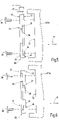
- the closing part 29 can thus be arranged in two different positions or orientations on the mounting surface 35 by resting against the mounting surface 35 either with the first attachment surface 32 or with the second attachment surface 33 ( Figures 5 and 6 ).
- figure 4 is a schematic sectional view along the mounting surface 35 with a view of the closing part 29, wherein the closing part 29 rests with the second attachment surface 33 on the mounting surface 35, so that the first side 30 of the closing part 29 is separated from the mounting surface 35 or the associated first base body 12 or second body 13 points away.
- the closing part 29 has a recess 38 on the side facing away from the carrier 14 .
- the recess 38 is open in a vertical direction H, which is oriented at right angles to the clamping direction R and at right angles to the carrier surface 15 .
- a threaded spindle 39 of the workpiece clamping device 11 can protrude in the clamping direction R into this recess 38 .
- the recess 38 is limited by a boundary surface 40 in the shape of a circular arc.
- the boundary surface 40 of the threaded spindle 39 forms an intermediate space opposite to.
- the boundary surface 40 could be in contact with the peripheral surface of the threaded spindle 39 at least in sections.
- the boundary surfaces 40 of the end parts 29 can be used as storage surfaces for the threaded spindle 39.
- the threaded spindle 39 of the workpiece clamping device 11 extends in the clamping direction R along the first base body 12 and along the second base body 13.
- the threaded spindle 39 has a first threaded section 41 in the area of the first base body 12 and a second threaded section 42 in the area of the second base body 13 first threaded section 41 has an opposite sense of rotation compared to second threaded section 42, with the slope being of the same amount.
- a first clamping body 45 is slidably mounted in the clamping direction R on the first base body 12 .
- a second clamping body 46 is slidably mounted in the clamping direction R on the second base body 13 .
- a clamping surface or holding surface for acting on a workpiece to be clamped can be present on each clamping body 45 .
- a connecting device for arranging a separate clamping jaw can be present on the clamping body 45, 46, which in turn has a clamping surface or holding surface for loading the workpiece.
- the first clamping body 45 is in engagement with the first threaded section 41 via a counter-thread, not shown.
- the second clamping body 46 is in engagement with the second threaded section 42, via a counter-thread, not shown.
- the clamping bodies 45, 46 move around their spindle longitudinal axis towards or away from one another, depending on the direction of rotation of the threaded spindle 39.
- the first clamping body 45 covers the same path relative to the first base body 12 as the second clamping body 46 does relative to the second base body 13. This movement of the clamping bodies 45, 46 allows a workpiece to be clamped or released.
- the threaded spindle 39 is supported exclusively or mainly via the clamping bodies 45, 46 and the base bodies 12, 13 on the carrier 14. As mentioned, when the clamping bodies are replaced or removed, the threaded spindle 39 can be placed on the boundary surfaces 40 of the end parts 29 and is thus roughly pre-positioned for the renewed arrangement of clamping bodies 45, 46 on the base bodies 12, 13.
- the threaded spindle 39 In order to ensure that the workpiece is clamped centered in relation to the center plane M, the threaded spindle 39 must be centered in the clamping direction R.
- the threaded spindle 39 has a centering body 47 which has a first centering surface 48 facing the first base body 12 and a second centering surface 49 facing the second base body 13 .
- the centering surfaces 48, 49 are in particular in figure 7 to recognize.
- the centering surfaces 48, 49 can extend parallel to one another and, in particular, at right angles to the clamping direction R.
- the first centering surface 48 rests against the contact surface 27 or 28 of the closing part 29 arranged on the first base body 12 .
- the second centering surface 49 rests against the contact surface 27 or 28 of the closing part 29 attached to the second base body 13 .
- the centering body 47 Due to the contact of the first contact surfaces 27 or the second contact surfaces 28 on the associated centering surface 48 or 49, the centering body 47 is positioned precisely between the two end parts 29 in the clamping direction R and thereby defines the position of the central plane M.
- the central plane M runs in Clamping direction R in the middle between the first centering surface 48 and the second centering surface 49 through the centering body 47.
- the closing parts 29 in the preferred exemplary embodiment described here can be attached in different orientations to the respectively assigned base body 12, 13. If the distance between the mounting surfaces 35 of the two base bodies 12, 13 varies in the clamping direction R due to mounting tolerances in different mounting positions on the carrier 14, the end parts 29 can be mounted in the appropriate orientation so that the centering body 47 is in contact with the respective contact surfaces 27 or 28, but on the other hand is not subjected to too high a clamping force in order not to impede the rotation of the threaded spindle 39 and to avoid excessive wear.
- first contact surfaces 27 each have a first distance d1 from the associated mounting surface 35 when they face the centering body 47 and the second contact surfaces 28 each have a second distance d2 from the associated mounting surface 35 when they face the centering body 47 are facing.
- each closing part 29 it is not absolutely necessary for each closing part 29 to provide different distances d1, d2 and/or to be able to be attached to a mounting surface 35 in different orientations.
- the closing part 29 can also be plate-shaped, with it having parallel surfaces on both sides and thus providing or would provide the same spacing between the centering body 47 and the contact surfaces 27, 28 in both orientations. It is also possible to provide end parts 29 with different dimensions in the form of a modular system, so that the end parts 29 with the appropriate dimensions can be selected. If tolerance compensation or play compensation in the clamping direction R is not required, a single type of end part 29 with a single contact surface and a single attachment surface is sufficient.
- the threaded spindle 39 can be constructed in several parts.
- the threaded spindle 39 has a first spindle part 50 with the first threaded section 41 and a second spindle part 52 with the second threaded section 42.
- the threaded sections 41, 42 end at a distance from the respective end part 29.
- each spindle part 50, 51 has an end section 52.
- the end section 52 can have an external thread, at least in one area, which is designed to be screwed into a corresponding internal thread of the centering body 47.
- the end portion 52 may also be stepped with different diameters to form an annular surface that acts as a stop is used and can interact with a corresponding counter-stop surface on or in the centering body 47 .
- the relative position of each spindle part 50, 51 relative to the centering body 47 in the clamping direction R can be set very precisely by the stop and the counter-stop.
- each spindle part 50, 51 is connected to the centering body 47 by means of an adhesion-promoting connection in addition to the screw connection.
- centering body 47 has, for example, hollow-cylindrical sections or is designed as a hollow cylinder, it forms a centering sleeve.
- FIG. 1-3 different arrangements 10 are illustrated, which can be constructed by means of a workpiece clamping device 11 described above.
- two workpiece clamping devices 11 are arranged next to one another in such a way that their threaded spindles 39 extend parallel to one another in a longitudinal direction L and are spaced apart from one another in a transverse direction Q, which is perpendicular to the longitudinal direction L.
- the centering takes place in such a way that the two centering bodies 47 are arranged centrally or symmetrically relative to a common center plane M.
- the threaded spindles 39 of the two workpiece clamping devices 11 are arranged crossed to form a crossing point 55 .
- the threaded spindles 39 are offset in the vertical direction H to one another.
- One threaded spindle extends in the longitudinal direction L and the other threaded spindle extends at right angles thereto in the transverse direction Q.
- the arrangement is such that the center plane M defined by the one centering body 47 runs along the longitudinal axis of the spindle of the respective other threaded spindle.
- FIG 8 shows another embodiment of a workpiece clamping device 11.
- the base body 12, 13 are not connected to the carrier 14 and illustrated in a kind of exploded view.
- the structure of the workpiece clamping device 11 corresponds to one of the exemplary embodiments described above, with the difference that each base body 12, 13 is not formed from a single, integral body, but rather has a plurality of base body parts.
- the base bodies 12 , 13 each have a first base body part 56 and a second base body part 57 .
- the two base body parts 56, 57 are in particular of different lengths.
- the second base body part 57 can have at most or exactly half the length in the longitudinal direction L as the first base body part 56.
- connection point between the two base body parts 56, 57 there is preferably a coupling device 58 in order to couple the two base body parts 56, 57 to one another and to align them relative to one another at least in one spatial direction, so that along the two base body parts 56, 57 precise guidance for the respective clamping body 45, 46 is provided. Adjacent to the coupling device 58, the two base body parts 56, 57 rest against one another with the surfaces facing one another at the connection point.
- the coupling device 58 can have at least one coupling body 59 which protrudes in the longitudinal direction L or clamping direction R away from one of the base body parts 56, 57 and engages in an associated coupling recess 60 on the respective other base body part 57 or 56. Due to the precise dimensioning of the coupling body 59 with the coupling recess 60, the two base body parts 56, 57 can be precisely aligned relative to one another ( Figures 9 and 10 ).
- the at least one coupling body 59 is screwed to one of the base body parts, for example on the first base body part 56, and can alternatively also be fastened by other means.
- the outer dimension of the coupling body 59 is dimensioned such that it corresponds to the inner dimension of the coupling recess 60 in the transverse direction Q, apart from a technically required play. This achieves an exact positioning of the two base body parts 56, 57 in the transverse direction Q relative to one another.
- the longitudinal direction L and/or in a vertical direction perpendicular to the longitudinal direction L and to the transverse direction Q there is play between the at least one coupling body 59 and the associated coupling recess 60. Overdetermination can thereby be avoided.
- the second base body part 57 has fewer fastening pins 17 than the first base body part 56.
- the first base body part 56 has at least four and, for example, exactly four fastening pins, while the second base body part 57 has fewer than four and, for example, two fastening pins 17.
- the exact positioning of the second base body part 57 by means of the fastening device 16 on the carrier 14 is not always guaranteed and the orientation of the two base body parts 56, 57 is additionally specified by the coupling device 58, at least in the transverse direction Q.
- a connecting body 61 can be present, which connects the two base bodies 12, 13 to one another and can bridge a gap between the two base bodies 12, 13.
- the connecting body 61 is arranged at a distance from the carrier 14 and is not in contact with the carrier 14 or is not attached directly to the carrier 14 .
- the connecting body 61 can form a cover and cover the centering body 47 and/or the closing parts 29 .
- each base body 12, 13 in the region of the end which has the mounting surface 35 can have several and, for example, two fastening openings 62, for example threaded holes 63 ( Figures 1-3 ).
- a fastening pin 64 which is connected to the connecting body 61 can engage in the fastening openings 62 in order to fasten the connecting body 61 to the first base body 12 or to the second base body 13 .
- each fastening pin 64 is formed by a fastening screw 65 which engages in the thread of the threaded bore 63, so that the connecting body 61 is attached both to the first base body 12 and to the second base body 13 by a screw connection.
- the connecting body 61 serves to connect the two base bodies 12, 13 and has no guiding function for positioning the centering body 47.
- the centering body 47 is positioned exclusively through and between the closing parts 29 .
- the aspect of the construction of the base bodies 12, 13 from a plurality of base body parts 56, 57 and their coupling with a coupling device 58 and/or the aspect of the connection of the two base bodies 12, 13 by means of a separate connecting body 61 can also be carried out independently of other described configurations of the workpiece clamping device 11 are used and thus represent separate, independent aspects of the invention.
- the invention relates to a workpiece clamping device 11 with a first base body 12 on which a first clamping body 45 is mounted so that it can be displaced in a clamping direction R, and with a second base body 13 on which a second clamping body 46 is mounted so that it can be displaced in the clamping direction R.
- the two clamping bodies 45, 46 are in engagement with a threaded spindle 39.
- a contact surface 27 or 28 is arranged on each base body 12, 13 on the side facing the other base body 13 or 12, respectively. In the clamping direction R, the contact surfaces are arranged to form a base body distance x.
- a centering body 47 of the threaded spindle 39 has centering surfaces 48, 49 which each rest against an associated contact surface 27 or 28 in order to position the threaded spindle in the clamping direction R with as little play as possible.
Description
Die Erfindung betrifft eine Werkstückspannvorrichtung, die zum Einspannen eines Werkstücks eingerichtet ist. Hierzu hat die Werkstückspannvorrichtung zwei Klemmkörper, die in einer Spannrichtung durch Antreiben einer Gewindespindel aufeinander zu oder voneinander weg bewegt werden können, um ein Werkstück zu spannen bzw. zu lösen.The invention relates to a workpiece clamping device that is designed to clamp a workpiece. For this purpose, the workpiece clamping device has two clamping bodies which can be moved towards or away from one another in a clamping direction by driving a threaded spindle in order to clamp or release a workpiece.
Eine Werkstückspannvorrichtung ist beispielsweise aus
Ein weiteres Beispiel geht aus der
Ausgehend vom Stand der Technik ist es eine Aufgabe der vorliegenden Erfindung, die Gewindespindel gegenüber einer Mittelebene auf einfache Weise zu zentrieren und eine schnelle und einfache Wartung der Werkstückspannvorrichtung zu gewährleisten.Proceeding from the prior art, it is an object of the present invention to center the threaded spindle relative to a central plane in a simple manner and to ensure quick and easy maintenance of the workpiece clamping device.
Diese Aufgabe wird durch eine Werkstückspannvorrichtung mit den Merkmalen des Patentanspruches 1 gelöst.This problem is solved by a workpiece clamping device with the features of
Die Werkstückspannvorrichtung hat einen ersten Grundkörper und einen zweiten Grundkörper. Beide Grundkörper haben an der Stirnseite, die dem jeweils anderen Grundkörper zugewandt ist, eine Kontaktfläche. In einer Spannrichtung liegen sich die Kontaktflächen der beiden Grundkörper mit einem Grundkörperabstand gegenüber. Der Grundkörperabstand ist durch den Abstand zwischen der Kontaktfläche des ersten Grundkörpers und der Kontaktfläche des zweiten Grundkörpers definiert.The workpiece clamping device has a first base body and a second base body. Both base bodies have a contact surface on the end face that faces the respective other base body. In a clamping direction, the contact surfaces of the two base bodies face each other at a base body distance. The base body distance is defined by the distance between the contact surface of the first base body and the contact surface of the second base body.
Die beiden Grundkörper sind mit einer Grundfläche auf einem Träger befestigt, insbesondere lösbar befestigt. Zur Befestigung kann eine Befestigungseinrichtung dienen. Jeder Grundkörper kann über eine separate Befestigungseinrichtung auf dem Träger befestigt sein. Der Träger kann aus einer oder mehreren Trägerplatten bestehen. Die lösbare Befestigung der Grundkörper am Träger kann durch eine kraftschlüssige und/oder formschlüssige Verbindung realisiert werden.The two base bodies are fastened with a base on a carrier, in particular detachably fastened. A fastening device can be used for fastening. Each base body can be attached to the carrier via a separate attachment device. The carrier can consist of one or more carrier plates. The detachable attachment of the base body to the carrier can be realized by a non-positive and/or positive connection.
Am ersten Grundkörper ist ein erster Klemmkörper in Spannrichtung verschiebbar gelagert. Am zweiten Grundkörper ist ein zweiter Klemmkörper in Spannrichtung verschiebbar gelagert. Die Klemmkörper können jeweils eine Klemmfläche aufweisen, mit der sie ein Werkstück zum Einspannen beaufschlagen. Zusätzlich oder alternativ kann an jedem Klemmkörper eine Spannbacke angebracht werden, an der eine Klemmfläche zum Einspannen eines Werkstücks vorhanden ist.A first clamping body is movably mounted in the clamping direction on the first base body. A second clamping body is mounted on the second base body so that it can be displaced in the clamping direction. The clamping bodies can each have a clamping surface with which they act on a workpiece for clamping. Additionally or alternatively, a clamping jaw can be attached to each clamping body, on which there is a clamping surface for clamping a workpiece.
Die Werkstückspannvorrichtung weist außerdem eine sich in Spannrichtung erstreckende Gewindespindel auf. Die Gewindespindel hat einen ersten Gewindeabschnitt, der mit einem Gegengewinde des ersten Klemmkörpers in Eingriff steht. Die Gewindespindel hat außerdem einen zweiten Gewindeabschnitt, der mit einem Gegengewinde des zweiten Klemmkörpers in Eingriff steht. Der erste Gewindeabschnitt und der zweite Gewindeabschnitt haben unterschiedliche Drehrichtungen bzw. Drehsinne. Der Betrag der Steigung ist im ersten Gewindeabschnitt und im zweiten Gewindeabschnitt gleich groß. Bei einer Drehung der Gewindespindel um ihre Spindellängsachse bewegen sich die beiden Klemmkörper jeweils um den gleichen Weg relativ zu einem ortsfesten Koordinatensystems aufeinander zu oder voneinander weg.The workpiece clamping device also has a threaded spindle extending in the clamping direction. the The threaded spindle has a first threaded section which engages with a mating thread of the first clamp body. The threaded spindle also has a second threaded section which engages with a mating thread of the second clamp body. The first threaded section and the second threaded section have different directions of rotation or senses of rotation. The amount of the pitch is the same in the first thread section and in the second thread section. When the threaded spindle rotates about its longitudinal spindle axis, the two clamping bodies each move towards or away from one another by the same distance relative to a stationary coordinate system.
Zwischen den beiden Gewindeabschnitten weist die Gewindespindel einen Zentrierkörper auf. Der Zentrierkörper hat in Spannrichtung auf beiden Seiten jeweils eine Zentrierfläche. Die beiden Zentrierflächen definieren eine Mittelebene, die in Spannrichtung mittig zwischen den beiden Zentrierflächen angeordnet ist und rechtwinklig zur Spannrichtung ausgerichtet ist. Vorzugsweise ist der Zentrierkörper rotationssymmetrisch. Der Zentrierkörper kann beispielsweise eine zylindrische Außenkontur aufweisen und insbesondere als Zentrierhülse ausgebildet sein.The threaded spindle has a centering body between the two threaded sections. The centering body has a centering surface on both sides in the clamping direction. The two centering surfaces define a center plane which is arranged centrally between the two centering surfaces in the clamping direction and is aligned at right angles to the clamping direction. The centering body is preferably rotationally symmetrical. The centering body can have a cylindrical outer contour, for example, and can be designed in particular as a centering sleeve.
Der Zentrierkörper liegt mit einer Zentrierfläche an der Kontaktfläche des ersten Grundkörpers und mit seiner anderen, entgegengesetzten Zentrierfläche an der Kontaktfläche des zweiten Grundkörpers an. Dadurch ist gewährleistet, dass sich die Mittelebene genau zwischen den beiden Kontaktflächen und mithin zwischen den beiden Grundkörpern befindet. Ein Werkstück kann daher mittels der Klemmkörper von entgegengesetzten Seiten gegenüber der Mittelebene zentriert gespannt werden.The centering body rests with one centering surface on the contact surface of the first base body and with its other, opposite centering surface on the contact surface of the second base body. This ensures that the center plane is located exactly between the two contact surfaces and therefore between the two base bodies. A workpiece can therefore be clamped by means of the clamping body from opposite sides in a centered manner with respect to the central plane.
Diese Ausgestaltung der Werkstückspannvorrichtung weist einen sehr einfachen Aufbau auf. Zur Zentrierung der Gewindespindel relativ zu den Grundkörpern ist es nicht erforderlich, zwischen den Grundkörpern ein Lager vorzusehen, das die Gewindespindel am Träger für die Werkstückspannvorrichtung lagert. Die Gewindespindel stützt sich ausschließlich oder hauptsächlich über die Klemmkörper und die Grundkörper am Träger ab.This configuration of the workpiece clamping device has a very simple structure. To center the threaded spindle relative to the base bodies, it is not necessary to provide a bearing between the base bodies that supports the threaded spindle on the carrier for the workpiece clamping device. The threaded spindle is supported exclusively or mainly via the clamping body and the base body on the carrier.
Die Zentrierung der Gewindespindel erfolgt über einen Gleitlagerkontakt zwischen den zwei Flächenpaaren bestehend aus jeweils einer Kontaktfläche und jeweils einer Zentrierfläche.The threaded spindle is centered via a plain bearing contact between the two pairs of surfaces, each consisting of a contact surface and a centering surface.
Es ist vorteilhaft, wenn jeder Grundkörper ein Abschlussteil aufweist, das die Kontaktfläche aufweist. Bevorzugt sind die Abschlussteile separat zu den Grundkörpern ausgeführt und insbesondere jeweils lösbar am zugeordneten Grundkörper befestigt. Hierzu kann der Grundkörper eine im Wesentlichen rechtwinklig zur Spannrichtung ausgerichtete Montagefläche aufweisen. Wenn die Abschlussteile als separate Elemente, beispielsweise plattenförmige Elemente, ausgebildet sind, kann für die Abschlussteile ein Material zur Herstellung ausgewählt werden, das nicht mit dem Material der Grundkörper übereinstimmen muss. Das Abschlussteil kann zusätzlich oder alternativ mit einer Beschichtung versehen werden. Weiterhin kann das Abschlussteil oder zumindest die wenigstens eine Kontaktfläche des Abschlussteils durch Schleifen oder ein anderes hoch genaues Verfahren präzise gefertigt werden. Die Bearbeitung des Abschlussteils zur Erzeugung der Kontaktfläche ist vereinfacht, wenn es unabhängig vom Grundkörper gehandhabt werden kann.It is advantageous if each base body has a closing part that has the contact surface. The closing parts are preferably designed separately from the base bodies and in particular are each detachably fastened to the associated base body. For this purpose, the base body can have a mounting surface that is aligned essentially at right angles to the clamping direction. If the terminating parts are designed as separate elements, for example plate-shaped elements, a material can be selected for production for the terminating parts that does not have to match the material of the base body. The closing part can additionally or alternatively be provided with a coating. Furthermore, the terminating part or at least the at least one contact surface of the terminating part can be precisely manufactured by grinding or another highly precise method. The processing of the final part to create the contact surface is simplified if it can be handled independently of the base body.
Bei einer bevorzugten Ausführungsform hat das Abschlussteil mehrere Kontaktflächen. Vorzugsweise hat jedes Abschlussteil an einer ersten Seite eine erste Kontaktfläche und an einer der ersten Seite entgegengesetzten zweiten Seite eine zweite Kontaktfläche. Dabei ist es vorteilhaft, wenn jedes Abschlussteil an der ersten Seite eine erste Anbringungsfläche und an der zweiten Seite eine zweite Anbringungsfläche aufweist. Die Anbringungsflächen sind dazu eingerichtet, das Abschlussteil an der Montagefläche des zugeordneten Grundkörpers lösbar anzubringen. Somit kann jedes Abschlussteil in zwei unterschiedlichen Positionen bzw. Orientierungen am zugeordneten Grundkörper angeordnet sein. Dabei kann entweder die erste Kontaktfläche oder die zweite Kontaktfläche mit der benachbarten Zentrierfläche des Zentrierkörpers zur Anlage gelangen.In a preferred embodiment, the termination part has multiple contact surfaces. Preferably, each termination part has a first contact surface on a first side and a second contact surface on a second side opposite the first side. It is advantageous if each closing part has a first attachment surface on the first side and a second attachment surface on the second side. The attachment surfaces are designed to detachably attach the end piece to the mounting surface of the associated base body. Thus, each terminating part can be arranged in two different positions or orientations on the associated base body. Either the first contact surface or the second contact surface can come into contact with the adjacent centering surface of the centering body.
Bei der Ausgestaltung des Abschlussteils mit mehreren Kontaktflächen, können die Kontaktflächen in Spannrichtung unterschiedliche Abstände zu den Anbringungsflächen aufweisen. Insbesondere ist bei einem bevorzugten Ausführungsbeispiel zwischen der ersten Kontaktfläche und der zweiten Anbringungsfläche in Spannrichtung ein erster Abstand vorhanden und zwischen der zweiten Kontaktfläche und der ersten Anbringungsfläche ist in Spannrichtung ein zweiter Abstand vorhanden. Der erste Abstand und der zweite Abstand weisen unterschiedliche Beträge auf. Durch diese Ausgestaltung hat die dem Zentrierkörper zugewandte erste Kontaktfläche einen anderen Abstand von der Montagefläche des Grundkörpers, wenn das Abschlussteil mit der zweiten Anbringungsfläche an der Montagefläche anliegt als bei einer Orientierung des Abschlussteils, wenn die zweite Kontaktfläche dem Zentrierkörper zugewandt ist und die erste Anbringungsfläche an der Montagefläche anliegt. Durch diese Ausgestaltung der Abschlussteile können Toleranzen beim Befestigen der Grundkörper auf dem Träger ausgeglichen werden, so dass der Zentrierkörper klemmfrei zwischen entweder zwei ersten Kontaktflächen oder zwei zweiten Kontaktflächen der Abschlussteile angeordnet werden kann. Die Differenz zwischen dem ersten Abstand und dem zweiten Abstand kann vorzugsweise kleiner als 1 mm.In the configuration of the closing part with a plurality of contact surfaces, the contact surfaces can have different distances from the attachment surfaces in the clamping direction. In particular, in a preferred embodiment, there is a first distance between the first contact surface and the second attachment surface in the clamping direction and a second distance is present between the second contact surface and the first attachment surface in the clamping direction. The first distance and the second distance have different amounts. This configuration means that the first contact surface facing the centering body is at a different distance from the mounting surface of the base body when the closing part is in contact with the second mounting surface on the mounting surface than when the closing part is oriented when the second contact surface is facing the centering body and the first mounting surface against the mounting surface. This configuration of the terminating parts allows tolerances to be compensated for when fastening the base body on the carrier, so that the centering body can be arranged between either two first contact surfaces or two second contact surfaces of the terminating parts without jamming. The difference between the first distance and the second distance can preferably be less than 1 mm.
Es ist vorteilhaft, wenn die erste Kontaktfläche und die erste Anbringungsfläche an der ersten Seite des Abschlussteils in einer gemeinsamen Ebene angeordnet sind. An der zweiten Seite kann das Abschlussteil eine Stufe aufweisen, die die zweite Anbringungsfläche und die zweite Kontaktfläche trennt, insbesondere derart, dass sich die zweite Anbringungsfläche und die zweite Kontaktfläche in parallelen Ebenen erstrecken, die in Spannrichtung zueinander versetzt sind.It is advantageous if the first contact surface and the first attachment surface are arranged in a common plane on the first side of the closing part. On the second side, the end piece may have a step separating the second attachment surface and the second contact surface, in particular such that the second attachment surface and the second contact surface extend in parallel planes that are offset from one another in the spanwise direction.
Bei einer weiteren bevorzugten Ausführungsform weist jedes Abschlussteil eine Aussparung auf, die insbesondere auf einer der Gewindespindel zugewandten Seite offen ist. Die Gewindespindel kann sich durch die Aussparung des Abschlussteils hindurch erstrecken. In Spannrichtung betrachtet kann die Aussparung zumindest in einem Abschnitt einen kreisbogenförmigen Verlauf aufweisen, dessen Radius größer ist als der Radius der Gewindespindel an der durch die Aussparung verlaufenden Stelle.In a further preferred embodiment, each closing part has a recess which is open in particular on a side facing the threaded spindle. The threaded spindle can extend through the recess of the closing part. Viewed in the clamping direction, the recess can have a course in the form of a circular arc, at least in one section, the radius of which is greater than the radius of the threaded spindle at the point running through the recess.
Eine die Aussparung des Abschlussteils begrenzende Fläche kann als Begrenzungsfläche dienen. Die Begrenzungsfläche liegt der Gewindespindel vorzugsweise mit Abstand gegenüber, wenn die Gewindespindel in Eingriff ist mit den Gegengewinden der Klemmkörper. Beim Austausch von Klemmkörper können die Begrenzungsflächen der Abschlussteile als Ablageflächen für die Gewindespindel verwendet werden.A surface delimiting the recess of the closing part can serve as a delimiting surface. The limiting surface preferably faces the lead screw at a distance when the lead screw is engaged with the mating threads of the clamping bodies. When replacing the clamping body, the boundary surfaces of the end parts can be used as storage areas for the threaded spindle.
Es ist vorteilhaft, wenn die Gewindespindel ein erstes Spindelteil mit dem ersten Gewindeabschnitt und ein davon separates zweites Spindelteil mit dem zweiten Gewindeabschnitt aufweist. Bevorzugt sind die beiden Spindelteile durch eine formschlüssige Verbindung und/oder eine kraftschlüssige Verbindung und/oder eine stoffschlüssige Verbindung und/oder eine Haftvermittlungsverbindung mittelbar oder unmittelbar miteinander verbunden. Bei einer bevorzugten Ausführungsform sind die beiden Spindelteile mittels des Zentrierkörpers miteinander verbunden. Bei dieser Ausgestaltung kann der Zentrierkörper vorzugsweise hülsenförmig sein und die einander zugewandten Enden der Spindelteile aufnehmen. Es ist vorteilhaft, wenn die Verbindung zwischen den Enden der Spindelteile und dem Zentrierkörper jeweils durch einen Gewindeeingriff und eine zusätzliche Haftverbindung hergestellt wird. Dies stellt sicher, dass sich die Verbindung beim drehenden Antreiben der Gewindespindel nicht löst.It is advantageous if the threaded spindle has a first spindle part with the first threaded section and a separate second spindle part with the second threaded section. The two spindle parts are preferably connected to one another directly or indirectly by a positive connection and/or a non-positive connection and/or a material connection and/or an adhesion-promoting connection. In a preferred embodiment, the two spindle parts are connected to one another by means of the centering body. In this configuration, the centering body can preferably be sleeve-shaped and accommodate the ends of the spindle parts that face one another. It is advantageous if the connection between the ends of the spindle parts and the centering body is produced by a threaded engagement and an additional adhesive connection. This ensures that the connection does not come loose when the threaded spindle is driven in rotation.
Mittels der vorstehend beschriebenen Ausführungsbeispiele der Werkstückspannvorrichtung können Anordnungen mit wenigstens zwei Werkstückspannvorrichtungen aufgebaut werden. Beispielsweise kann eine Anordnung wenigstens zwei Werkstückspannvorrichtungen aufweisen, deren Gewindespindeln sich parallel zueinander und mit Abstand zueinander in einer Längsrichtung erstrecken. Dabei sind die beiden Zentrierkörper insbesondere derart angeordnet, dass sie eine gemeinsame Mittelebene definieren und in Längsrichtung symmetrisch bzw. mittig zu dieser gemeinsamen Mittelebene angeordnet sind. Dadurch lässt sich ein Werkstück mittels vier oder mehr Klemmkörpern zentriert zur Mittelebene einspannen.Arrangements with at least two workpiece clamping devices can be constructed using the exemplary embodiments of the workpiece clamping device described above. For example, an arrangement can have at least two workpiece clamping devices, the threaded spindles of which extend parallel to one another and at a distance from one another in a longitudinal direction. The two centering bodies are in particular arranged in such a way that they define a common center plane and are symmetrical in the longitudinal direction or are arranged centrally to this common center plane. This allows a workpiece to be clamped centered on the median plane using four or more clamping bodies.
Bei einer weiteren Anordnung kann sich die Gewindespindel der einen Werkstückspannvorrichtung in einer Längsrichtung erstrecken und die Gewindespindel der weiteren Werkstückspannvorrichtung kann sich in einer Querrichtung rechtwinklig zur Längsrichtung erstrecken. Die beiden Gewindespindeln kreuzen sich dabei an einer Kreuzungsstelle. An der Kreuzungsstelle können die Gewindespindeln in einer Höhenrichtung, die rechtwinklig zur Längsrichtung und rechtwinklig zur Querrichtung ausgerichtet ist, versetzt zueinander angeordnet sein. Bei dieser Anordnung erstreckt sich die Mittelebene des Zentrierkörpers der einen Gewindespindel vorzugsweise entlang der Spindellängsachse der jeweils anderen Gewindespindel.In another arrangement, the lead screw of one workpiece fixture may extend in a longitudinal direction and the lead screw of the other workpiece fixture may extend in a transverse direction perpendicular to the longitudinal direction. The two threaded spindles cross each other at a crossing point. At the crossing point, the threaded spindles can be offset from one another in a vertical direction that is aligned at right angles to the longitudinal direction and at right angles to the transverse direction. In this arrangement, the center plane of the centering body of one threaded spindle preferably extends along the longitudinal axis of the spindle of the other threaded spindle.
Wenn eine Anordnung mehr als zwei Werkstückspannvorrichtungen aufweist, können die Klemmkörper verschiedener Werkstückspannvorrichtungen unterschiedlich ausgestaltet sein. Beispielsweise kann ein Werkstück über den ersten Klemmkörper und den zweiten Klemmkörper einer der Werkstückspannvorrichtungen hauptsächlich gehalten und gespannt werden, während die Klemmkörper der einen oder der mehreren weiteren Werkstückspannvorrichtungen zum zusätzlichen Stützen des Werkstücks verwendet werden.If an arrangement has more than two workpiece clamping devices, the clamping bodies of different workpiece clamping devices can be configured differently. For example, a workpiece may be primarily held and clamped via the first clamp body and the second clamp body of one of the workpiece fixtures, while the clamp bodies of the one or more other workpiece fixtures are used to additionally support the workpiece.
Vorteilhafte Ausgestaltungen der Erfindung ergeben sich aus den abhängigen Patentansprüchen, der Beschreibung und den Zeichnungen. Nachfolgend werden bevorzugte Ausführungsbeispiele der Erfindung anhand der beigefügten Zeichnungen im Einzelnen erläutert. In den Zeichnungen zeigen:
-
Figuren 1-3 jeweils eine perspektivische Darstellung von unterschiedlichen Anordnungen aufweisend jeweils zwei erfindungsgemäße Werkstückspannvorrichtungen, -
Figur 4 eine teilgeschnittene Darstellung durch einen Grundkörper entlang einer Anbringungsfläche eines am Grundkörper angeordneten Abschlussteils in schematischer Darstellung, -
Figuren 5 und 6 jeweils eine schematische Prinzipdarstellung zum Anordnen eines Ausführungsbeispiels eines Abschlussteils in unterschiedlichen Ausrichtungen, -
Figur 7 eine schematische teilweise geschnittene Teildarstellung eines Ausführungsbeispiels einer Werkstückspannvorrichtung im Bereich einer Mittelebene, -
Figur 8 eine perspektivische Darstellung von weiteren Ausführungsbeispielen einer Werkstückspannvorrichtung mit Grundkörpern, die mehrere gekoppelte Grundkörperteile aufweisen, -
Figur 9 einen Längsschnitt durch ein Ausführungsbeispiel der Werkstückspannvorrichtung ausFigur 8 und -
Figur 10
-
Figures 1-3 each having a perspective view of different arrangements each having two workpiece clamping devices according to the invention, -
figure 4 a partially sectioned representation through a base body along an attachment surface of a closure part arranged on the base body in a schematic representation, -
Figures 5 and 6 in each case a schematic basic representation for arranging an embodiment of a final part in different orientations, -
figure 7 a schematic partially sectioned partial representation of an embodiment of a workpiece clamping device in the area of a central plane, -
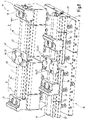
figure 8 a perspective view of further exemplary embodiments of a workpiece clamping device with base bodies that have a plurality of coupled base body parts, -
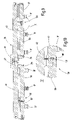
figure 9 a longitudinal section through an embodiment of the workpiece clamping devicefigure 8 and -
figure 10 an enlarged detail X from Figure 9 at a junction between two body parts.
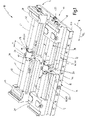
In den
Jede Werkstückspannvorrichtung 11 hat einen ersten Grundkörper 12 und einen zweiten Grundkörper 13. Die beiden Grundkörper sind dazu eingerichtet, die Werkstückspannvorrichtung 11 an einem Träger 14 anzuordnen. Der Träger 14 weist eine zumindest abschnittsweise ebene Trägerfläche 15 auf. Jeder Grundkörper 12, 13 hat eine Unterseite, die zumindest abschnittsweise eben ist und die dazu eingerichtet ist, auf der Trägerfläche 15 des Trägers 14 angeordnet zu werden.Each
Mittels einer Befestigungseinrichtung 16 (
Zu der Befestigungseinrichtung 16 gehören mehrere Schieber 19, die in Kanälen 20 des Trägers 14 verschiebbar angeordnet sind. Jeder Kanal 20 mündet in ein Loch 18, so dass ein freies Ende des Schiebers 19 einen in das Loch 18 eingeführten Befestigungsstift 17 mit einer Kraft beaufschlagen kann.The
Beim Ausführungsbeispiel weist jeder Befestigungsstift 17 eine ringsumlaufende Befestigungsnut 21 auf, die sich radial nach innen über zwei Schräg- oder Keilflächen verjüngt. Der Schieber hat einen Endabschnitt, der sich zu seinem freien Ende hin über Schräg- oder Keilflächen verjüngt, so dass er in die Befestigungsnut 21 eingreifen kann. Zum Spannen eines Grundkörpers 12, 13 am Träger 14 und gegen die Trägerfläche 15 werden über mehrere Schieber 19 auf die mehreren Befestigungsstifte 17 eines der Grundkörper 12, 13 sowohl eine Zugkraft entlang der Erstreckungsrichtung des Befestigungsstifts 17 ausgeübt, als auch der Befestigungsstift 17 gegen eine Umfangswand des Loches 18 gedrückt. Dadurch wird der Grundkörper 12, 13 mit seiner Grundfläche gegen die Trägerfläche 15 gezogen und gleichzeitig in der Ebene, in der sich die Trägerfläche 15 erstreckt, fixiert.In the exemplary embodiment, each
Wie bereits erwähnt, kann jeder Grundkörper 12, 13 vier Befestigungsstifte 17 aufweisen, so dass der Grundkörper mittels vier Schieber 19 am Träger 14 lösbar befestigt wird.As already mentioned, each
Der Träger 14 kann durch mehrere separate Trägerplatten 14a gebildet sein (
Der erste Grundkörper 12 und der zweite Grundkörper 13 einer gemeinsamen Werkstückspannvorrichtung 11 sind in einer Spannrichtung R mit einem definierten Grundkörperabstand x zueinander angeordnet. Der erste Grundkörper 12 weist auf der dem zweiten Grundkörper 13 zugewandten Seite eine Kontaktfläche auf, wobei es sich um eine erste Kontaktfläche 27 oder eine zweite Kontaktfläche 28 handeln kann. Der zweite Grundkörper 13 weist auf der dem ersten Grundkörper 12 zugewandten Seite ebenfalls eine Kontaktfläche auf, die wiederum auch von einer ersten Kontaktfläche 27 oder einer zweiten Kontaktfläche 28 gebildet sein kann. Die einander zugewandten ersten Kontaktflächen 27 oder zweiten Kontaktflächen 28 erstrecken sich parallel zu der Mittelebene M (
Sowohl am ersten Grundkörper 12, als auch am zweiten Grundkörper 13 ist ein separates Abschlussteil 29 angeordnet. Jedes Abschlussteil 29 hat eine erste Seite 30 und einer der ersten Seite 30 entgegengesetzte zweite Seite 31. An der ersten Seite 30 weist das Abschlussteil 29 die erste Kontaktfläche 27 auf. An der ersten Seite 30 weist das Abschlussteil 29 außerdem eine erste Anbringungsfläche 32 auf, die benachbart zur ersten Kontaktfläche 27 angeordnet ist. An der zweiten Seite 31 weist das Abschlussteil 29 die zweite Kontaktfläche 28 auf. An der zweiten Seite 31 weist das Abschlussteil 29 außerdem eine zweite Anbringungsfläche 33 auf, die benachbart zur zweiten Kontaktfläche 28 angeordnet ist.Both on the
Bei dem in den
Die erste Kontaktfläche 27, die zweite Kontaktfläche 28, die erste Anbringungsfläche 32 und die zweite Anbringungsfläche 33 sind vorzugsweise als ebene Flächen ausgebildet und erstrecken sich parallel zueinander und in montiertem Zustand parallel zur Mittelebene M. Die erste Kontaktfläche 27 hat in Spannrichtung R einen ersten Abstand d1 von der zweiten Anbringungsfläche 33. Die zweite Kontaktfläche 28 hat in Spannrichtung R einen zweiten Abstand d2 von der ersten Anbringungsfläche 32. Die Abstände sind schematisch in
Die erste Anbringungsfläche 32 und die zweite Anbringungsfläche 33 sind jeweils dazu eingerichtet, an einer Montagefläche 35 des ersten Grundkörpers 12 oder des zweiten Grundkörpers 13 anzuliegen, um das Abschlussteil 29 lösbar und beispielsgemäß mittels einer Schraubverbindung am ersten Grundkörper 12 oder am zweiten Grundkörper 13 anzubringen. Zur Herstellung der Schraubverbindung können mehrere und beispielsgemäß zwei Schrauben 36 verwendet werden, wie es beispielhaft schematisch in den
Das Abschlussteil 29 hat an der vom Träger 14 abgewandten Seite eine Aussparung 38. Die Aussparung 38 ist in einer Höhenrichtung H, die rechtwinklig zur Spannrichtung R und rechtwinklig zur Trägerfläche 15 orientiert ist, offen. In diese Aussparung 38 kann eine Gewindespindel 39 der Werkstückspannvorrichtung 11 in Spannrichtung R hindurchragen.The closing
Beim Ausführungsbeispiel ist die Aussparung 38 durch eine kreisbogenförmige Begrenzungsfläche 40 begrenzt. In vollständig montiertem Zustand liegt die Begrenzungsfläche 40 der Gewindespindel 39 unter Bildung eines Zwischenraums gegenüber. Alternativ könnte die Begrenzungsfläche 40 zumindest abschnittsweise in Kontakt mit der Umfangsfläche der Gewindespindel 39 stehen. Beim Austausch von Klemmkörper können die Begrenzungsflächen 40 der Abschlussteile 29 als Ablageflächen für die Gewindespindel 39 verwendet werden.In the exemplary embodiment, the
Die Gewindespindel 39 der Werkstückspannvorrichtung 11 erstreckt sich in Spannrichtung R entlang des ersten Grundkörpers 12 sowie entlang des zweiten Grundkörpers 13. Die Gewindespindel 39 hat im Bereich des ersten Grundkörpers 12 einen ersten Gewindeabschnitt 41 und im Bereich des zweiten Grundkörpers 13 einen zweiten Gewindeabschnitt 42. Der erste Gewindeabschnitt 41 hat einen gegenüber dem zweiten Gewindeabschnitt 42 entgegengesetzten Drehsinn, wobei die Steigung betragsmäßig gleich groß ist.The threaded
Am ersten Grundkörper 12 ist ein erster Klemmkörper 45 in Spannrichtung R verschiebbar gelagert. Am zweiten Grundkörper 13 ist ein zweiter Klemmkörper 46 in Spannrichtung R verschiebbar gelagert. An jedem Klemmkörper 45 kann eine Klemmfläche oder Haltefläche zur Beaufschlagung eines einzuspannenden Werkstücks vorhanden sein. Alternativ oder zusätzlich kann an dem Klemmkörper 45, 46 eine Verbindungseinrichtung zum Anordnen einer separaten Spannbacke vorhanden sein, die wiederum eine Klemmfläche oder Haltefläche zur Beaufschlagung des Werkstücks aufweist.A
Der erste Klemmkörper 45 steht über ein nicht veranschaulichtes Gegengewinde in Eingriff mit dem ersten Gewindeabschnitt 41. Der zweite Klemmkörper 46 steht über ein nicht veranschaulichtes Gegengewinde in Eingriff mit dem zweiten Gewindeabschnitt 42. Bei einer Drehung der Gewindespindel um ihre Spindellängsachse bewegen sich die Klemmkörper 45, 46 abhängig von der Drehrichtung der Gewindespindel 39 aufeinander zu oder voneinander weg. Dabei legt der erste Klemmkörper 45 relativ zum ersten Grundkörper 12 denselben Weg zurück wie der zweite Klemmkörper 46 relativ zum zweiten Grundkörper 13. Durch diese Bewegung der Klemmkörper 45, 46 kann ein Werkstück gespannt oder gelöst werden.The
Die Gewindespindel 39 stützt sich ausschließlich oder hauptsächlich über die Klemmkörper 45, 46 und die Grundkörper 12, 13 am Träger 14 ab. Wie erwähnt kann die Gewindespindel 39 bei einem Austausch oder Ausbau der Klemmkörper auf den Begrenzungsflächen 40 der Abschlussteile 29 abgelegt werden und ist dadurch grob vorpositioniert für das erneute Anordnen von Klemmkörpern 45, 46 an den Grundkörpern 12, 13.The threaded
Um das zentrierte Spannen des Werkstücks gegenüber der Mittelebene M zu gewährleisten, muss die Gewindespindel 39 in Spannrichtung R zentriert werden. Hierzu weist die Gewindespindel 39 einen Zentrierkörper 47 auf, der eine dem ersten Grundkörper 12 zugewandte erste Zentrierfläche 48 und eine dem zweiten Grundkörper 13 zugewandte zweite Zentrierfläche 49 aufweist. Die Zentrierflächen 48, 49 sind insbesondere in
Um Toleranzen beim Anordnen der Grundkörper 12, 13 auf dem Träger 14 auszugleichen, können die Abschlussteile 29 bei dem hier beschriebenen bevorzugten Ausführungsbeispiel in unterschiedlichen Orientierungen am jeweils zugeordneten Grundkörper 12, 13 angebracht werden. Wenn der Abstand zwischen den Montageflächen 35 der beiden Grundkörper 12, 13 in Spannrichtung R aufgrund von Montagetoleranzen in verschiedenen Anbringungspositionen auf dem Träger 14 variiert, können die Abschlussteile 29 in der geeigneten Orientierung angebracht werden, so dass der Zentrierkörper 47 Kontakt zu den jeweiligen Kontaktflächen 27 bzw. 28 hat, andererseits aber nicht mit einer zu hohen Klemmkraft beaufschlagt wird, um das Drehen der Gewindespindel 39 nicht zu behindern und einen übermäßigen Verschleiß zu vermeiden. Dieser Ausgleich wird dadurch ermöglicht, dass die ersten Kontaktflächen 27 jeweils einen ersten Abstand d1 zur zugeordneten Montagefläche 35 haben, wenn sie dem Zentrierkörper 47 zugewandt sind und die zweiten Kontaktflächen 28 jeweils einen zweiten Abstand d2 zur zugeordneten Montagefläche 35 haben, wenn sie dem Zentrierkörper 47 zugewandt sind.In order to compensate for tolerances when arranging the
In Abwandlung zum beschriebenen Ausführungsbeispiel ist es nicht zwingend erforderlich, dass jedes Abschlussteil 29 unterschiedliche Abstände d1, d2 bereitstellt und/oder in unterschiedlichen Orientierungen an einer Montagefläche 35 angebracht werden kann. Das Abschlussteil 29 kann auch plattenförmig sein, wobei das an beiden Seiten parallel Flächen aufweist und somit in beiden Orientierungen denselben Abstand zwischen dem Zentrierkörper 47 und den Kontaktflächen 27, 28 bereitstellt bzw. bereitstellen würde. Es ist auch möglich, unterschiedlich dimensionierte Abschlussteile 29 in Form eines Baukastensystems bereitzustellen, so dass die Abschlussteile 29 mit der geeigneten Dimensionierung ausgewählt werden können. Wenn ein Toleranzausgleich bzw. Spielausgleich in Spannrichtung R nicht benötigt wird, genügt ein einziger Typ eines Abschlussteils 29 mit einer einzigen Kontaktfläche und einer einzigen Anbringungsfläche.In a modification to the exemplary embodiment described, it is not absolutely necessary for each closing
Wie es in
Da der Zentrierkörper 47 beispielsgemäß hohlzylindrische Abschnitte aufweist oder hohlzylindrisch ausgebildet ist, bildet er eine Zentrierhülse.Since the centering
In den
Bei der Anordnung 10 gemäß
An der Verbindungsstelle zwischen den beiden Grundkörperteilen 56, 57 ist vorzugsweise eine Kopplungseinrichtung 58 vorhanden, um die beiden Grundkörperteile 56, 57 miteinander zu koppeln und zumindest in eine Raumrichtung relativ zueinander auszurichten, so dass entlang der beiden Grundkörperteile 56, 57 eine exakte Führung für den jeweiligen Klemmkörper 45, 46 bereitgestellt wird. Benachbart zur Kopplungseinrichtung 58 liegen die beiden Grundkörperteile 56, 57 mit den einander zugewandten Flächen an der Verbindungsstelle aneinander an.At the connection point between the two
Die Kopplungseinrichtung 58 kann beim Ausführungsbeispiel wenigstens einen Kopplungskörper 59 aufweisen, der in Längsrichtung L bzw. Spannrichtung R von einem der Grundkörperteile 56, 57 weg ragt und in eine zugeordnete Kopplungsaussparung 60 am jeweils anderen Grundkörperteil 57 bzw. 56 eingreift. Durch das passgenaue Dimensionieren des Kopplungskörpers 59 mit der Kopplungsaussparung 60 können die beiden Grundkörperteile 56, 57 relativ zueinander genau ausgerichtet werden (
Wie es insbesondere in
Aufgrund der kleineren Dimensionierung des zweiten Grundkörperteils 57 weist das zweite Grundkörperteil 57 weniger Befestigungsstifte 17 auf als das erste Grundkörperteil 56. Insbesondere hat das erste Grundkörperteil 56 mindestens vier und beispielsweise genau vier Befestigungsstifte, während das zweite Grundkörperteil 57 weniger als vier und beispielsgemäß zwei Befestigungsstifte 17 aufweist. Dadurch ist das exakte Positionieren des zweiten Grundkörperteils 57 mittels der Befestigungseinrichtung 16 am Träger 14 nicht immer gewährleistet und die Orientierung der beiden Grundkörperteile 56, 57 wird beispielsgemäß zusätzlich durch die Kopplungseinrichtung 58 vorgegeben, zumindest in Querrichtung Q.Due to the smaller dimensioning of the second
Wie es insbesondere in
Dazu kann jeder Grundkörper 12, 13 im Bereich des Endes, das die Montagefläche 35 aufweist, mehrere und beispielsgemäß zwei Befestigungsöffnungen 62 aufweisen, beispielsweise Gewindebohrungen 63 (
Insbesondere dient der Verbindungskörper 61 zur Verbindung der beiden Grundkörper 12, 13 und weist keine Führungsfunktion zur Positionierung des Zentrierkörpers 47 auf. Der Zentrierkörper 47 wird beispielsgemäß ausschließlich durch und zwischen den Abschlussteilen 29 positioniert.In particular, the connecting
Der Aspekt des Aufbaus der Grundkörper 12, 13 aus mehreren Grundkörperteilen 56, 57 und deren Kopplung mit einer Kopplungseinrichtung 58 und/oder der Aspekt der Verbindung der beiden Grundkörper 12, 13 mittels eines separaten Verbindungskörpers 61 können auch unabhängig von anderen beschriebenen Ausgestaltungen der Werkstückspannvorrichtung 11 verwendet werden und stellen somit separate, unabhängige erfindungsgemäße Aspekte dar.The aspect of the construction of the
Die Erfindung betrifft eine Werkstückspannvorrichtung 11 mit einem ersten Grundkörper 12, an dem ein erster Klemmkörper 45 in einer Spannrichtung R verschiebbar gelagert ist, sowie mit einem zweiten Grundkörper 13, an dem ein zweiter Klemmkörper 46 in Spannrichtung R verschiebbar gelagert ist. Die beiden Klemmkörper 45, 46 stehen in Eingriff mit einer Gewindespindel 39. An jedem Grundkörper 12, 13 ist auf der dem jeweils anderen Grundkörper 13 bzw. 12 zugewandten Seite eine Kontaktfläche 27 oder 28 angeordnet. In Spannrichtung R sind die Kontaktflächen unter Bildung eines Grundkörperabstands x angeordnet. Ein Zentrierkörper 47 der Gewindespindel 39 hat Zentrierflächen 48, 49, die jeweils an einer zugeordneten Kontaktfläche 27 oder 28 anliegen, um die Gewindespindel in Spannrichtung R möglichst spielfrei zu positionieren.The invention relates to a
- 1010
- Anordnungarrangement
- 1111
- Werkstückspannvorrichtungworkpiece clamping device
- 1212
- erster Grundkörperfirst body
- 1313
- zweiter Grundkörpersecond body
- 1414
- Trägercarrier
- 1515
- Trägerflächecarrier surface
- 1616
- Befestigungseinrichtungfastening device
- 1717
- Befestigungsstiftmounting pin
- 1818
- LochHole
- 1919
- Schieberslider
- 2020
- Kanalchannel
- 2121
- Befestigungsnutmounting groove
- 2222
- Betätigungselementactuator
- 2727
- erste Kontaktflächefirst contact surface
- 2828
- zweite Kontaktflächesecond contact surface
- 2929
- Abschlussteilfinal part
- 3030
- erste Seite des Abschlussteilsfirst page of the final part
- 3131
- zweite Seite des Abschlussteilssecond page of the final part
- 3232
- erste Anbringungsflächefirst mounting surface
- 3333
- zweite Anbringungsflächesecond mounting surface
- 3434
- StufeStep
- 3535
- Montageflächemounting surface
- 3838
- Aussparungrecess
- 3939
- Gewindespindellead screw
- 4040
- Begrenzungsflächeboundary surface
- 4141
- ersten Gewindeabschnittfirst thread section
- 4242
- zweiten Gewindeabschnittsecond thread section
- 4545
- erster Klemmkörperfirst clamp body
- 4646
- zweiter Klemmkörpersecond clamping body
- 4747
- Zentrierkörpercentering body
- 4848
- erste Zentrierflächefirst centering surface
- 4949
- zweite Zentrierflächesecond centering surface
- 5050
- erstes Spindelteilfirst spindle part
- 5151
- zweites Spindelteilsecond spindle part
- 5252
- Endabschnittend section
- 5555
- Kreuzungsstellecrossing point
- 5656
- erstes Grundkörperteilfirst body part
- 5757
- zweites Grundkörperteilsecond body part
- 5858
- Kopplungseinrichtungcoupling device
- 5959
- Kopplungskörpercoupling body
- 6060
- Kopplungsaussparungcoupling recess
- 6161
- Verbindungskörperconnecting body
- 6262
- Befestigungsöffnungmounting hole
- 6363
- Gewindebohrungthreaded hole
- 6464
- Befestigungsstiftmounting pin
- 6565
- Befestigungsschraubemounting screw
- xx
- Grundkörperabstandbody spacing
- d1d1
- erster Abstandfirst distance
- d2d2
- zweiter Abstandsecond distance
- HH
- Höhenrichtungheight direction
- LL
- Längsrichtunglongitudinal direction
- MM
- Mittelebenemidplane
- Querrichtungtransverse direction
- RR
- Spannrichtungclamping direction
Claims (15)
- Workpiece clamping device (11) comprisinga first base body (12) and a second base body (13), wherein a contact surface (27 or 28) is arranged on each base body (12, 13) on the face of each base body (12, 13) facing the respective other base body (13 or 12), wherein a base body distance (x) is defined between the contact surfaces (27 or 28) in a clamping direction (R),a first clamping body (45) that is movably supported on the base body (12) in clamping direction (R), a second clamping body (46) that is movably supported on the second base body (13) in clamping direction (R),a threaded spindle (39) extending in clamping direction (R) and having a first thread section (41) that is in engagement with a counter-thread on the first clamping body (45) and having a second thread section (42) that is in engagement with a counter-thread on the second clamping body (46), wherein the threaded spindle (39) comprises a centering body (47) arranged between the first thread section (41) and the second thread section (42) and abutting against the contact surfaces (27 or 28) facing each other.
- Workpiece clamping device according to claim 1, characterized in that each base body (12, 13) comprises a terminal part (29) on which the contact surface (27 or 28) is arranged.
- Workpiece clamping device according to claim 2, characterized in that the terminal parts (29) are separate from the base bodies (12, 13).
- Workpiece clamping device according to claim 3, characterized in that each terminal part (29) is releasably attached to the assigned base body (12, 13).
- Workpiece clamping device according to claim 4, characterized in that each terminal part (29) comprises a first contact surface (27) on a first side (30) and a second contact surface (28) on a second side (31) opposite the first side (30).
- Workpiece clamping device according to claim 5, characterized in that each terminal part (29) comprises a first attachment surface (32) on the first side (30) and a second attachment surface (33) on the second side (31) .
- Workpiece clamping device according to claim 6, characterized in that the first contact surface (27) and the second attachment surface (33) have a first distance (d1) from each other in clamping direction (R) and that the second contact surface (28) and the first attachment surface (32) have a second distance (d2) from each other in clamping direction (R), wherein the second distance (d2) is different from the first distance (d1).
- Workpiece clamping device according to claim 7, characterized in that each terminal part (29) comprises a step (34) on the second side (31) that separates the second attachment surface (33) from the second contact surface (28) .
- Workpiece clamping device according to any of the claims 6 to 8, characterized in that the terminal part (29) is attached to the assigned base body (12, 13) either with the first attachment surface (32) or with the second attachment surface (33).
- Workpiece clamping device according to any of the claims 2 to 9, characterized in that each terminal part (29) comprises a limiting surface (40) that is arranged opposite the threaded spindle (39).
- Workpiece clamping device according to any of the preceding claims, characterized in that the threaded spindle (39) comprises a first spindle part (50) having the first thread section (41) and a second spindle part (51) having the second thread section (42).
- Workpiece clamping device according to claim 11, characterized in that the first spindle part (50) and the second spindle part (51) are connected with each other by means of the centering body (47).
- Arrangement (10) comprising at least two workpiece clamping devices (11) according to one of the preceding claims, wherein the threaded spindles (39) extend parallel to one another in a longitudinal direction (L) and wherein the two centering bodies (47) are centrally arranged with regard to a common center plane (M) that is orientated orthogonal to the longitudinal direction (L).
- Arrangement (10) comprising at least two workpiece clamping devices (11) according to any of the preceding claims, wherein one of the threaded spindles (39) extends in a longitudinal direction (L) and another of the threaded spindles (39) extends in a transverse direction (Q) orientated orthogonal to the longitudinal direction (L) such that the threaded spindles (39) cross each other.
- Arrangement according to claim 14, characterized in that the centering body (47) of the one threaded spindle (39) is arranged symmetrically to a center plane (M) that extends along the spindle longitudinal axis of the other threaded spindle (39).
Applications Claiming Priority (1)
| Application Number | Priority Date | Filing Date | Title |
|---|---|---|---|
| DE102020101064.8A DE102020101064B3 (en) | 2020-01-17 | 2020-01-17 | Workpiece clamping device |
Publications (2)
| Publication Number | Publication Date |
|---|---|
| EP3851249A1 EP3851249A1 (en) | 2021-07-21 |
| EP3851249B1 true EP3851249B1 (en) | 2022-11-23 |
Family
ID=74175708
Family Applications (1)
| Application Number | Title | Priority Date | Filing Date |
|---|---|---|---|
| EP21151282.7A Active EP3851249B1 (en) | 2020-01-17 | 2021-01-13 | Workpiece clamping device |
Country Status (3)
| Country | Link |
|---|---|
| US (1) | US11801583B2 (en) |
| EP (1) | EP3851249B1 (en) |
| DE (1) | DE102020101064B3 (en) |
Families Citing this family (3)
| Publication number | Priority date | Publication date | Assignee | Title |
|---|---|---|---|---|
| DE102020101062B4 (en) * | 2020-01-17 | 2021-08-12 | Lang Technik Gmbh | Workpiece clamping device with coupling body between clamping body and threaded spindle |
| CN113751948A (en) * | 2021-07-27 | 2021-12-07 | 湖南敏锐科技有限公司 | Welding device for train junction box |
| DE202022104051U1 (en) | 2022-07-19 | 2022-07-25 | Kamil Słobiński | Collet for clamping workpieces on machine tools |
Family Cites Families (7)
| Publication number | Priority date | Publication date | Assignee | Title |
|---|---|---|---|---|
| DE102007003673B3 (en) * | 2007-01-18 | 2008-08-21 | Lang Technik Gmbh | Centering |
| US20090315238A1 (en) * | 2008-06-19 | 2009-12-24 | Pacific Bearing Company | Modular Adjustable Vise |
| US8690138B2 (en) * | 2010-12-29 | 2014-04-08 | Tseh-Pei LIN | Coaxial concentric double-jaw vice |
| CH707170B1 (en) * | 2012-11-09 | 2016-03-31 | Raphael Rogenmoser | A device for the concentric chucking of an article. |
| DE202014005498U1 (en) * | 2014-07-07 | 2014-08-12 | Kohn Spannwerkzeuge - Mechanische Teilefertigung Gmbh | Two-axis center tensioner |
| DE102014110352B3 (en) * | 2014-07-23 | 2015-10-08 | Gressel Ag | Centric jig |
| DE102017122112B4 (en) * | 2017-09-25 | 2021-12-09 | Lang Technik Gmbh | Vice device |
-
2020
- 2020-01-17 DE DE102020101064.8A patent/DE102020101064B3/en active Active
-
2021
- 2021-01-13 EP EP21151282.7A patent/EP3851249B1/en active Active
- 2021-01-15 US US17/150,179 patent/US11801583B2/en active Active
Also Published As
| Publication number | Publication date |
|---|---|
| EP3851249A1 (en) | 2021-07-21 |
| US20210220967A1 (en) | 2021-07-22 |
| DE102020101064B3 (en) | 2021-03-18 |
| US11801583B2 (en) | 2023-10-31 |
Similar Documents
| Publication | Publication Date | Title |
|---|---|---|
| EP3851249B1 (en) | Workpiece clamping device | |
| EP0613757A1 (en) | Workpiece clamping device | |
| DE102019116262B4 (en) | Clamping device and workpiece holding device with one clamping device | |
| EP0198379B1 (en) | Gripper with an exchangeable gripper jaw | |
| WO1994001242A1 (en) | Adapter for use with clamping devices on multi-hole machine-tool workpiece tables | |
| WO2012010463A1 (en) | Zero point clamping device | |
| DE3623099C3 (en) | Blow molding machine | |
| EP0873816B1 (en) | Cylinder for positioning and quick-action clamping | |
| DE10049348A1 (en) | Linear guide arrangement | |
| EP1048544A1 (en) | Articulated link for vehicle units of railway vehicles | |
| DE3634118C2 (en) | ||
| EP0275923A2 (en) | Clamping device for work pieces | |
| DE102014001963B4 (en) | Clamping device for reproducible, accurate clamping of workpieces | |
| EP3756820A1 (en) | Zero point clamping system for machine tools, especially rotary and / or milling machines | |
| DE3928971C2 (en) | ||
| EP3851250A1 (en) | Workpiece clamping device with coupling body between clamping body and threaded spindle | |
| DE3822473A1 (en) | DEVICE FOR COUPLING AND UNCOUPLING GRIPPER RAIL PARTS | |
| EP3964332A1 (en) | Clamping device | |
| DE3511580A1 (en) | Tool-clamping device | |
| DE19826328C1 (en) | Rapid change mounting for machine tool work clamp | |
| EP1904256A1 (en) | Chuck and rotary orienting device | |
| DE19830691C2 (en) | Device for clamping workpieces | |
| DE4012468C2 (en) | ||
| EP3616831A1 (en) | Clamping device | |
| DE4328841A1 (en) | Mechanical connection between two components (structural parts) |
Legal Events
| Date | Code | Title | Description |
|---|---|---|---|
| PUAI | Public reference made under article 153(3) epc to a published international application that has entered the european phase |
Free format text: ORIGINAL CODE: 0009012 |
|
| STAA | Information on the status of an ep patent application or granted ep patent |
Free format text: STATUS: THE APPLICATION HAS BEEN PUBLISHED |
|
| AK | Designated contracting states |
Kind code of ref document: A1 Designated state(s): AL AT BE BG CH CY CZ DE DK EE ES FI FR GB GR HR HU IE IS IT LI LT LU LV MC MK MT NL NO PL PT RO RS SE SI SK SM TR |
|
| STAA | Information on the status of an ep patent application or granted ep patent |
Free format text: STATUS: REQUEST FOR EXAMINATION WAS MADE |
|
| 17P | Request for examination filed |
Effective date: 20220114 |
|
| RBV | Designated contracting states (corrected) |
Designated state(s): AL AT BE BG CH CY CZ DE DK EE ES FI FR GB GR HR HU IE IS IT LI LT LU LV MC MK MT NL NO PL PT RO RS SE SI SK SM TR |
|
| GRAP | Despatch of communication of intention to grant a patent |
Free format text: ORIGINAL CODE: EPIDOSNIGR1 |
|
| STAA | Information on the status of an ep patent application or granted ep patent |
Free format text: STATUS: GRANT OF PATENT IS INTENDED |
|
| INTG | Intention to grant announced |
Effective date: 20220622 |
|
| GRAS | Grant fee paid |
Free format text: ORIGINAL CODE: EPIDOSNIGR3 |
|
| GRAA | (expected) grant |
Free format text: ORIGINAL CODE: 0009210 |
|
| STAA | Information on the status of an ep patent application or granted ep patent |
Free format text: STATUS: THE PATENT HAS BEEN GRANTED |
|
| AK | Designated contracting states |
Kind code of ref document: B1 Designated state(s): AL AT BE BG CH CY CZ DE DK EE ES FI FR GB GR HR HU IE IS IT LI LT LU LV MC MK MT NL NO PL PT RO RS SE SI SK SM TR |
|
| REG | Reference to a national code |
Ref country code: GB Ref legal event code: FG4D Free format text: NOT ENGLISH |
|
| REG | Reference to a national code |
Ref country code: CH Ref legal event code: EP |
|
| REG | Reference to a national code |
Ref country code: AT Ref legal event code: REF Ref document number: 1532850 Country of ref document: AT Kind code of ref document: T Effective date: 20221215 Ref country code: DE Ref legal event code: R096 Ref document number: 502021000261 Country of ref document: DE |
|
| REG | Reference to a national code |
Ref country code: IE Ref legal event code: FG4D Free format text: LANGUAGE OF EP DOCUMENT: GERMAN |
|
| REG | Reference to a national code |
Ref country code: LT Ref legal event code: MG9D |
|
| REG | Reference to a national code |
Ref country code: NL Ref legal event code: MP Effective date: 20221123 |
|
| PG25 | Lapsed in a contracting state [announced via postgrant information from national office to epo] |
Ref country code: SE Free format text: LAPSE BECAUSE OF FAILURE TO SUBMIT A TRANSLATION OF THE DESCRIPTION OR TO PAY THE FEE WITHIN THE PRESCRIBED TIME-LIMIT Effective date: 20221123 Ref country code: PT Free format text: LAPSE BECAUSE OF FAILURE TO SUBMIT A TRANSLATION OF THE DESCRIPTION OR TO PAY THE FEE WITHIN THE PRESCRIBED TIME-LIMIT Effective date: 20230323 Ref country code: NO Free format text: LAPSE BECAUSE OF FAILURE TO SUBMIT A TRANSLATION OF THE DESCRIPTION OR TO PAY THE FEE WITHIN THE PRESCRIBED TIME-LIMIT Effective date: 20230223 Ref country code: LT Free format text: LAPSE BECAUSE OF FAILURE TO SUBMIT A TRANSLATION OF THE DESCRIPTION OR TO PAY THE FEE WITHIN THE PRESCRIBED TIME-LIMIT Effective date: 20221123 Ref country code: FI Free format text: LAPSE BECAUSE OF FAILURE TO SUBMIT A TRANSLATION OF THE DESCRIPTION OR TO PAY THE FEE WITHIN THE PRESCRIBED TIME-LIMIT Effective date: 20221123 Ref country code: ES Free format text: LAPSE BECAUSE OF FAILURE TO SUBMIT A TRANSLATION OF THE DESCRIPTION OR TO PAY THE FEE WITHIN THE PRESCRIBED TIME-LIMIT Effective date: 20221123 |
|
| PGFP | Annual fee paid to national office [announced via postgrant information from national office to epo] |
Ref country code: FR Payment date: 20230130 Year of fee payment: 3 |
|
| PG25 | Lapsed in a contracting state [announced via postgrant information from national office to epo] |
Ref country code: RS Free format text: LAPSE BECAUSE OF FAILURE TO SUBMIT A TRANSLATION OF THE DESCRIPTION OR TO PAY THE FEE WITHIN THE PRESCRIBED TIME-LIMIT Effective date: 20221123 Ref country code: PL Free format text: LAPSE BECAUSE OF FAILURE TO SUBMIT A TRANSLATION OF THE DESCRIPTION OR TO PAY THE FEE WITHIN THE PRESCRIBED TIME-LIMIT Effective date: 20221123 Ref country code: LV Free format text: LAPSE BECAUSE OF FAILURE TO SUBMIT A TRANSLATION OF THE DESCRIPTION OR TO PAY THE FEE WITHIN THE PRESCRIBED TIME-LIMIT Effective date: 20221123 Ref country code: IS Free format text: LAPSE BECAUSE OF FAILURE TO SUBMIT A TRANSLATION OF THE DESCRIPTION OR TO PAY THE FEE WITHIN THE PRESCRIBED TIME-LIMIT Effective date: 20230323 Ref country code: HR Free format text: LAPSE BECAUSE OF FAILURE TO SUBMIT A TRANSLATION OF THE DESCRIPTION OR TO PAY THE FEE WITHIN THE PRESCRIBED TIME-LIMIT Effective date: 20221123 Ref country code: GR Free format text: LAPSE BECAUSE OF FAILURE TO SUBMIT A TRANSLATION OF THE DESCRIPTION OR TO PAY THE FEE WITHIN THE PRESCRIBED TIME-LIMIT Effective date: 20230224 |
|
| PG25 | Lapsed in a contracting state [announced via postgrant information from national office to epo] |
Ref country code: NL Free format text: LAPSE BECAUSE OF FAILURE TO SUBMIT A TRANSLATION OF THE DESCRIPTION OR TO PAY THE FEE WITHIN THE PRESCRIBED TIME-LIMIT Effective date: 20221123 |
|
| PG25 | Lapsed in a contracting state [announced via postgrant information from national office to epo] |
Ref country code: SM Free format text: LAPSE BECAUSE OF FAILURE TO SUBMIT A TRANSLATION OF THE DESCRIPTION OR TO PAY THE FEE WITHIN THE PRESCRIBED TIME-LIMIT Effective date: 20221123 Ref country code: RO Free format text: LAPSE BECAUSE OF FAILURE TO SUBMIT A TRANSLATION OF THE DESCRIPTION OR TO PAY THE FEE WITHIN THE PRESCRIBED TIME-LIMIT Effective date: 20221123 Ref country code: EE Free format text: LAPSE BECAUSE OF FAILURE TO SUBMIT A TRANSLATION OF THE DESCRIPTION OR TO PAY THE FEE WITHIN THE PRESCRIBED TIME-LIMIT Effective date: 20221123 Ref country code: DK Free format text: LAPSE BECAUSE OF FAILURE TO SUBMIT A TRANSLATION OF THE DESCRIPTION OR TO PAY THE FEE WITHIN THE PRESCRIBED TIME-LIMIT Effective date: 20221123 Ref country code: CZ Free format text: LAPSE BECAUSE OF FAILURE TO SUBMIT A TRANSLATION OF THE DESCRIPTION OR TO PAY THE FEE WITHIN THE PRESCRIBED TIME-LIMIT Effective date: 20221123 |
|
| REG | Reference to a national code |
Ref country code: DE Ref legal event code: R097 Ref document number: 502021000261 Country of ref document: DE |
|
| PG25 | Lapsed in a contracting state [announced via postgrant information from national office to epo] |
Ref country code: SK Free format text: LAPSE BECAUSE OF FAILURE TO SUBMIT A TRANSLATION OF THE DESCRIPTION OR TO PAY THE FEE WITHIN THE PRESCRIBED TIME-LIMIT Effective date: 20221123 Ref country code: AL Free format text: LAPSE BECAUSE OF FAILURE TO SUBMIT A TRANSLATION OF THE DESCRIPTION OR TO PAY THE FEE WITHIN THE PRESCRIBED TIME-LIMIT Effective date: 20221123 |
|
| PG25 | Lapsed in a contracting state [announced via postgrant information from national office to epo] |
Ref country code: LU Free format text: LAPSE BECAUSE OF NON-PAYMENT OF DUE FEES Effective date: 20230113 |
|
| PLBE | No opposition filed within time limit |
Free format text: ORIGINAL CODE: 0009261 |
|
| STAA | Information on the status of an ep patent application or granted ep patent |
Free format text: STATUS: NO OPPOSITION FILED WITHIN TIME LIMIT |
|
| REG | Reference to a national code |
Ref country code: BE Ref legal event code: MM Effective date: 20230131 |
|
| 26N | No opposition filed |
Effective date: 20230824 |
|
| PG25 | Lapsed in a contracting state [announced via postgrant information from national office to epo] |
Ref country code: SI Free format text: LAPSE BECAUSE OF FAILURE TO SUBMIT A TRANSLATION OF THE DESCRIPTION OR TO PAY THE FEE WITHIN THE PRESCRIBED TIME-LIMIT Effective date: 20221123 Ref country code: BE Free format text: LAPSE BECAUSE OF NON-PAYMENT OF DUE FEES Effective date: 20230131 |
|
| PG25 | Lapsed in a contracting state [announced via postgrant information from national office to epo] |
Ref country code: IE Free format text: LAPSE BECAUSE OF NON-PAYMENT OF DUE FEES Effective date: 20230113 |
|
| PGFP | Annual fee paid to national office [announced via postgrant information from national office to epo] |
Ref country code: DE Payment date: 20231129 Year of fee payment: 4 |