EP3982102B1 - Procédé et dispositif pour mesurer la puissance optique locale et/ou la répartition de puissance optique d'un verre de lunettes - Google Patents
Procédé et dispositif pour mesurer la puissance optique locale et/ou la répartition de puissance optique d'un verre de lunettes Download PDFInfo
- Publication number
- EP3982102B1 EP3982102B1 EP21209645.7A EP21209645A EP3982102B1 EP 3982102 B1 EP3982102 B1 EP 3982102B1 EP 21209645 A EP21209645 A EP 21209645A EP 3982102 B1 EP3982102 B1 EP 3982102B1
- Authority
- EP
- European Patent Office
- Prior art keywords
- scene
- spectacle lens
- image
- refractive power
- capture device
- Prior art date
- Legal status (The legal status is an assumption and is not a legal conclusion. Google has not performed a legal analysis and makes no representation as to the accuracy of the status listed.)
- Active
Links
Images


Classifications
-
- G—PHYSICS
- G01—MEASURING; TESTING
- G01M—TESTING STATIC OR DYNAMIC BALANCE OF MACHINES OR STRUCTURES; TESTING OF STRUCTURES OR APPARATUS, NOT OTHERWISE PROVIDED FOR
- G01M11/00—Testing of optical apparatus; Testing structures by optical methods not otherwise provided for
- G01M11/02—Testing optical properties
- G01M11/0228—Testing optical properties by measuring refractive power
-
- G—PHYSICS
- G02—OPTICS
- G02C—SPECTACLES; SUNGLASSES OR GOGGLES INSOFAR AS THEY HAVE THE SAME FEATURES AS SPECTACLES; CONTACT LENSES
- G02C13/00—Assembling; Repairing; Cleaning
- G02C13/003—Measuring during assembly or fitting of spectacles
- G02C13/005—Measuring geometric parameters required to locate ophtalmic lenses in spectacles frames
-
- G—PHYSICS
- G02—OPTICS
- G02C—SPECTACLES; SUNGLASSES OR GOGGLES INSOFAR AS THEY HAVE THE SAME FEATURES AS SPECTACLES; CONTACT LENSES
- G02C7/00—Optical parts
- G02C7/02—Lenses; Lens systems ; Methods of designing lenses
- G02C7/06—Lenses; Lens systems ; Methods of designing lenses bifocal; multifocal ; progressive
- G02C7/061—Spectacle lenses with progressively varying focal power
- G02C7/063—Shape of the progressive surface
-
- G—PHYSICS
- G06—COMPUTING OR CALCULATING; COUNTING
- G06T—IMAGE DATA PROCESSING OR GENERATION, IN GENERAL
- G06T7/00—Image analysis
- G06T7/70—Determining position or orientation of objects or cameras
- G06T7/73—Determining position or orientation of objects or cameras using feature-based methods
- G06T7/74—Determining position or orientation of objects or cameras using feature-based methods involving reference images or patches
-
- G—PHYSICS
- G06—COMPUTING OR CALCULATING; COUNTING
- G06T—IMAGE DATA PROCESSING OR GENERATION, IN GENERAL
- G06T7/00—Image analysis
- G06T7/70—Determining position or orientation of objects or cameras
- G06T7/73—Determining position or orientation of objects or cameras using feature-based methods
- G06T7/75—Determining position or orientation of objects or cameras using feature-based methods involving models
Definitions
- the invention relates to a method for measuring the local refractive power and/or the refractive power distribution of a left and/or right spectacle lens, preferably in a spectacle frame.
- the invention relates to a computer program product with a computer program with program code and a device for carrying out the method.
- progressive lenses enable spectacle wearers to see clearly in different usage situations, e.g. at different distances, just by changing the direction of gaze, without the eyes requiring greater accommodation.
- progressive lenses are lenses with at least one progressive surface and an increasing (positive) dioptric effect when the wearer looks downwards.
- Individualised lenses and/or progressive lenses have one or more reference points, e.g.
- the distance visual point is, according to DIN EN ISO 13666:2013-10, paragraph 5.16, the assumed position of the visual point on a lens for seeing into the distance under certain conditions.
- the near visual point is, according to DIN EN ISO 13666:2013-10, paragraph 5.17, the assumed position of the visual point on a spectacle lens for near vision under certain conditions. In toric lens designs, there is also the need for the correct orientation of their cylindrical power for a spectacle wearer.
- a method and a device of the type mentioned at the beginning is known.
- This describes the measurement of the local refractive power of a left and/or right spectacle lens in a spectacle frame using a measuring device in which the spectacle frame is arranged.
- This measuring device contains an image capture device and a display for displaying a test structure, the position of which is known relative to the image capture device.
- the image capture device is used to capture the test structure displayed on the display using an imaging beam path that passes through the left and/or right spectacle lens in the spectacle frame.
- a section of the spectacle frame is captured using the display, which defines a coordinate system of the spectacle frame.
- the local refractive power of a left and/or right spectacle lens is then determined using image processing from the captured section of the spectacle frame and the captured image of the test structure as well as from the coordinates of the test structure and the captured image of the test structure in a coordinate system referenced to the coordinate system of the spectacle frame.
- the EP 2 608 109 A1 discloses a method for determining the refractive power of a spectacle lens in the wearing position.
- a photo of the wearer of the spectacles without the frame and a photo of the wearer of the spectacles with the frame are taken and the size of the iris is determined in both photos.
- the refractive power of the spectacle lens is determined from the difference in size and the focal length of the camera. For this method, it is necessary that the glasses are worn by the wearer. In addition, this method enables no local determination of the refractive power at individual points on the lens nor the determination of the individual rays of light through the lens.
- the US 2015/0362998 A1 and the US 10,019,140 B1 each describe methods for determining the distance of a person’s face from an image capture device capturing that face using photogrammetry.
- a method for measuring the refractive power of glasses is known in which the refractive power of the lens is determined from the difference in size of an object between a picture taken without a lens and a picture taken through the lens.
- the WO 2017/134275 A1 describes the measurement of the global refractive power of a left and/or right spectacle lens in a spectacle frame by evaluating at least one image of a left and/or right spectacle lens in a spectacle frame that is captured against a background whose geometry is either known or estimated. In addition, at least one image of the background without the spectacle frame is captured. Only a global refractive power of the front and back surfaces of the lens is determined from the images, but no local refractive power at different locations on the lens or a refractive power distribution.
- the US 2015/0029323 A1 describes an image processing device with a memory and with a processor coupled to the memory, which serves to determine the optical properties of a pair of glasses by evaluating images of the wearer of the glasses, which are captured by an image capture device and which show the wearer of the glasses with and without glasses.
- the US 2015/0029323 A1 is specified based on the spatial position of a facial contour of the face of a spectacle wearer captured through a pair of spectacles with spectacle lenses and the spatial position of a captured facial contour this face glasses to determine the refractive power of a lens in the glasses.
- the object of the invention is to determine the focusing or dioptric effect of a left and/or right spectacle lens for distance and/or near vision in a simple manner and without great expenditure on equipment.
- At least one first image of a scene is captured from at least one first recording position by means of at least one image capture device, wherein this at least one first image has many structural points and contains a left and/or a right spectacle lens in a spectacle frame, wherein the at least one imaging beam path for each of these structural points passes through the first or the second spectacle lens of the spectacle frame.
- This invention understands the refractive power to be the focusing effect or the dioptric effect of a spectacle lens.
- This invention understands the focusing effect to be the collective term for the spherical and astigmatic effect of a spectacle lens in accordance with the definition given in DIN EN ISO 13666:2013-10, paragraph 9.2.
- This invention understands the dioptric effect of a spectacle lens in accordance with the definition given in DIN EN ISO 13666:2013-10, paragraph 9.3.
- This invention understands the dioptric effect of a spectacle lens to be the collective term for the focusing and prismatic effect of the spectacle lens in accordance with the definition given in DIN EN ISO 13666:2013-10, paragraph 9.3.
- This invention understands the prismatic effect of a spectacle lens as the collective term for prismatic deflection and base position according to the definition given in DIN EN ISO 13666:2013-10, paragraph 10.9.
- local refractive power means the local focusing effect or the local dioptric effect of a spectacle lens.
- refractive power distribution means the spatially resolved focusing effect or the spatially resolved dioptric effect of a spectacle lens.
- the invention understands a scene to be a section of an environment that can be captured with at least one image capture device, e.g. with at least one digital camera that is integrated, for example, in a smartphone or a tablet computer.
- a scene can be, for example, a section of a room in an apartment or a section of a shop or a part of a landscape.
- a scene can also contain a face or just a left eye and/or a right eye of a person wearing the glasses.
- At least one structural point of a scene is understood to mean a geometric point whose image can be clearly recognized in at least one image or recording of the scene by capturing the scene with at least one image capture device due to a brightness and/or color of an image of points adjacent to this point that is different from the image of this point.
- a structural point can, for example, be located at a corner or edge of a structure in the scene.
- the term structural point of a scene also includes a point in a stationary, time-invariant pattern, e.g. at least one point in a regular or irregular point pattern, at least one point in a regular or irregular stripe pattern, at least one point in a regular or irregular checkered pattern, at least one point in a barcode, at least one point in a 2D code and/or at least one point within a written text, for example a newspaper or a book or an electronic display device, eg a screen.
- at least one stationary, time-invariant structural point in a scene can be at least one point on a structured surface, for example a structured tablecloth or on a structured wallpaper.
- the term structural point of a scene is also understood here to mean at least one point in a scene whose position can change over time, such as at least one point in the face of a glasses wearer that is moving, such as a point on the eyebrows, on the lips or a point on the iris. If the position of the at least one structural point in a scene changes over time, its displacement is preferably reconstructed as far as possible and then taken into account when determining the local refractive power of a left and/or right spectacle lens. In the event that the displacement of such a structural point cannot be reconstructed, it is advantageous if this structural point is not taken into account when determining the local refractive power and/or the refractive power distribution of a left and/or right spectacle lens.
- the invention preferably understands at least one image capture device to be a digital camera, which is integrated, for example, in a mobile terminal such as a mobile phone, a smartphone or a tablet computer.
- the digital camera can be designed as a stereo camera, as a multi-camera, as an image sensor with one lens or as an image sensor with at least two lenses and/or as a so-called plenoptic camera. It should be noted that a mobile terminal specified as standing can also have several image capture devices in the form of a digital camera.
- a mobile terminal is understood to mean in particular a device which comprises at least one programmable processor and at least one image capture device, e.g. at least one camera, and at least one acceleration sensor, and which is preferably designed to be carried, i.e. is designed in such a way in terms of dimensions and weight that it can be carried by a person.
- the mobile terminal can contain further components, such as at least one screen, at least one light source for, for example, visible light from a wavelength range of 380 nm to 780 nm and/or infrared light from a wavelength range of 780 nm to 1 mm and/or at least one light receiver with a sensitivity for, for example, visible light from a wavelength range of 380 nm to 780 nm and/or infrared light from a wavelength range of >780 nm to 1 mm.
- Typical examples of such mobile devices are smartphones or tablet PCs, which can have at least one screen, for example a sensor screen (touchscreen), at least one image capture device, e.g. at least one camera, at least one acceleration sensor, at least one light source, at least one light receiver and other components, such as wireless interfaces for mobile communications or WLAN (wireless LAN).
- an imaging beam path for a structural point is understood to mean the course of the light rays that cause an optical imaging of the structural point from the scene as a structural point image into the image of the scene in at least one image capture device.
- the main ray of the imaging beam path for a structural point is referred to below as the optical axis that forms an axis of symmetry.
- a further step which may be before or after the first step or may be carried out simultaneously with the first, at least two further images of the scene are created without the first and/or the second spectacle lens of the spectacle frame or without the spectacle frame containing the first and/or the second spectacle lens with the structural points depicted in the first image is captured by means of at least one image capture device from at least two different recording positions, wherein at least one of the recording positions can be identical to the at least one first recording position.
- the at least one image capture device can be identical or different to the at least one image capture device from the first step.
- the at least one image capture device in the further step is identical to the at least one image capture device from the first step.
- the coordinates of the structural points in a coordinate system are determined from the at least two further images of the scene by means of image evaluation using triangulation.
- the local refractive power is determined in a step of determining a local refractive power for at least a portion of the left spectacle lens and/or a portion of the right spectacle lens from the coordinates of the structure points and the image of the structure points in the at least one first image of the scene by means of an inverse approach in which the optical interfaces of the left and/or right spectacle lens are calculated from the imaging beam paths for the structure points by minimizing an error size by varying the interface to be determined in each case, wherein the error size for the interface is determined by using ray tracing to create a comparison of beam points in front of and behind the interface.
- the method specified in claim 2 for measuring the local refractive power of a left and/or a right spectacle lens in a spectacle frame provides, in a first step, for capturing at least one first image of a scene from at least one first recording position by means of at least one image capturing device, wherein this at least one first image has many structure points and a left and/or a right spectacle lens in a spectacle frame, wherein the at least one imaging beam path for each of these structural points passes through the first or the second spectacle lens of the spectacle frame.
- the imaging beam path for a structural point is understood here to mean the course of the light rays that cause an optical imaging of the structural point from the scene as a structural point image in the image of the scene captured by at least one image capture device.
- the optical axis forming an axis of symmetry is referred to below as the main ray of the imaging beam path for a structural point.
- a further step which can be before or after the first step or can take place at the same time as the first step, at least two further images of the scene with the left and/or right spectacle lens in a spectacle frame are captured by means of at least one image capture device from at least two different further recording positions different from the first recording position, each with at least one imaging beam path for the structural points depicted in the first image, wherein this at least one imaging beam path does not pass through the first and second spectacle lenses of the spectacle frame.
- the coordinates of the structural points in a coordinate system are calculated from the respective at least one beam path of the structural points that did not pass through the left and right spectacle lenses by means of image analysis using triangulation.
- the local refractive power for at least one section of the left spectacle lens and/or for at least one section of the right spectacle lens is determined from the coordinates of the structure points and the image of the structure points in the at least one first image of the scene by means of an inverse approach in which the optical interfaces of the left and/or right
- the optical properties of a spectacle lens can be calculated by minimizing an error size by varying the interface to be determined in each case, whereby the error size at the interface is determined by using ray tracing to create a comparison of ray points in front of and behind the interface.
- a plurality of structural points in a scene are recorded from at least one first recording position in a first image of the scene, and the steps following the recording are carried out on the basis of this respective plurality of structural points.
- a plurality of structural points is understood to mean a set of points consisting of at least three structural points. It is advantageous if the local refractive power of a left and/or right spectacle lens is measured using at least 10, preferably at least 100, particularly preferably at least 1000 and very particularly preferably at least 10,000 structural points. It is advantageous if the local refractive power of a left and/or right spectacle lens is measured using a number Z of structural points for which the following applies: 100 ⁇ Z ⁇ 1000.
- each image preferably includes image processing technologies such as classification, segmentation and triangulation.
- object recognition such as segmentation and classification
- each image is preferably examined for objects of the scene and/or spectacle frame classes.
- the methods for object recognition can be of a classical nature such as thresholding, edge- or region-based segmentation, optical flow or learning in nature. If the object recognition methods are of a learning nature, as is the case when learning algorithms are used, it is necessary to train a neural network with augmented training data in advance.
- the result of each of these object recognition methods is the position, location and boundary of the objects, here the classes scene and/or spectacle frame. Additional information is the existence of the respective objects in the respective images.
- the structural points can each be only stationary or both stationary and time-invariant.
- the displacement of the at least one structural point can be known and/or its displacement can be reconstructed and taken into account when determining the refractive power distribution.
- the structural points are each stationary, particularly preferably each stationary and time-invariant.
- the edge or the edge curve of the left and/or right spectacle lens in a spectacle frame is captured.
- the edge curve is preferably the shape-determining boundary of the lens located on the front surface of the spectacle frame facing away from the face, which in the case of half-rim or full-rim glasses partially or completely coincides with the front, inner edge of the spectacle frame.
- the edge curve on the front surface of the spectacle frame facing away from the face is equal to the front outer edge of the lens or the front inner edge of the frame.
- the edge curve on the front surface of the spectacle frame facing away from the face is equal to the front outer edge of the lens or the front inner edge of the frame, provided that a structure provided by the frame exists.
- edge curve on the front surface of the spectacle frame facing away from the face is equal to the front outer edge of the lens.
- edge curve In the case of rimless glasses, there is no analogous structure of the frame, i.e. the term edge curve always refers to the outer edge of the lens on the front surface of the frame facing away from the face.
- an image capture device arranged in a mobile terminal which contains at least two digital cameras, a stereo camera, a multi-camera, a camera chip with at least two lenses or a plenoptic camera, it may be sufficient to capture a single image of the scene with the spectacle frame containing the first and/or the second spectacle lens, wherein this first image has at least one structural point, and to capture a single further image of the scene without the spectacle frame containing the first and/or the second spectacle lens with the same structural points of the first image of a scene.
- at least two images of the scene with the spectacle frame containing the first and/or the second spectacle lens and at least two images of the scene without the spectacle frame containing the first and/or the second spectacle lens are captured.
- an image capture device arranged in a mobile terminal which contains at least two digital cameras, a stereo camera, a multi-camera, a camera chip with at least two lenses or a plenoptic camera, it can be sufficient to capture a single image of the scene with the spectacle frame containing the first and/or the second spectacle lens, wherein this first image has at least one structural point, wherein the at least one imaging beam path for each of these structural points passes through the first and/or the second spectacle lens, and to capture a single further image of the scene with the spectacle frame containing the first and/or the second spectacle lens, wherein this at least one further image is recorded from a recording position different from the first recording position, so that the at least one imaging beam path for each of these structural points does not pass through the first and the second spectacle lens of the spectacle frame.
- in order to increase its accuracy preferably at least two first images with the spectacle frame and at least two further images of the scene with the spectacle frame are created from recording
- the scene for determining the local refractive power and/or the refractive power distribution of a left and/or right spectacle lens preferably in a spectacle frame, has at least one structural point, preferably at least one stationary, time-invariant structural point, which is detected through a left and/or right spectacle lens and which has a distance from the spectacle lens to be measured which is preferably between 5 mm and 200 mm.
- the distance of a structural point from a spectacle lens is understood to mean the distance of the structural point to the point of intersection of the main ray of the imaging beam path on the side of the spectacle lens facing the structural point. It should be noted that by capturing further images of the scene from further, different recording positions, it is fundamentally possible to specify the main ray for an optical image in the image capture device for each structural point in the distance range specified above.
- the scene for determining the local refractive power and/or the refractive power distribution of a left and/or right spectacle lens preferably in a spectacle frame, contains at least one structural point, preferably at least one stationary, time-invariant structural point, which is detected through a left and/or right spectacle lens and which has a distance from the spectacle lens to be measured that is preferably in front of the focal point of the stronger main section. This distance is preferably between 5 mm and 100 mm.
- good measurement results are achieved in scenes with at least one structural point, preferably at least one stationary, time-invariant structural point, the distance of which from the spectacle lens to be measured, preferably in a spectacle frame, is up to 600 mm, preferably in a range of 5 mm to 500 mm.
- a finding of the invention is in particular that the local refractive power and/or refractive power distribution of a spectacle lens can be determined very precisely using the method according to the invention if the distance of at least one structural point, preferably at least one stationary, time-invariant structural point, in a scene from a spectacle lens in a spectacle frame is between 10 mm and 50 mm, preferably between 30 mm and 40 mm.
- An advantageous embodiment of the invention provides that a plurality of first images of the scene and a plurality of further images of the scene are recorded, each including the spectacle lens whose local refractive power and/or refractive power distribution is to be determined, whereby this spectacle lens is preferably located in a spectacle frame.
- the spectacle frame can also be removed from the scene when recording the plurality of further images.
- these span at least part of a hemisphere or a hemisphere around the scene and/or cover a plurality of different recording positions with different recording directions and/or recording distances.
- the coordinates of the at least one structural point can then be calculated from the plurality of further images of the scene.
- a correspondingly large number of captured first images of the scene and captured further images of the scene increase the accuracy of the method for measuring the local refractive power and/or the refractive power distribution of a left and/or a right spectacle lens, preferably in a spectacle frame.
- the image capture device By using the image capture device to capture a plurality of images of the scene, in particular of the head, while displacing the at least one Image capture device or, in the case of a stationary image capture device, with rotation of the scene, in particular of the head, wherein the left eye and/or the right eye of the spectacle wearer of the spectacle frame looks towards the displaced image capture device and, from the multitude of images of the scene, in particular of the head, captured in this process, viewing beam paths for different viewing directions of the left eye and/or right eye of the spectacle wearer of the spectacle frame through the left spectacle lens and/or the right spectacle lens are calculated and a local refractive power k(x, y) of the left spectacle lens and/or the right spectacle lens is determined for each viewing direction, it is possible to determine the local refractive power of the spectacle lenses in the spectacle frame worn by the spectacle wearer for a viewing direction selected by a spectacle wearer.
- a binocular effect is the assessment of the focusing or dioptric effect of the left and right lenses for a specific direction of view.
- a binocular effect can also include higher-order imaging errors of the lens, such as coma, or prismatic errors.
- the measurement of the local refractive power and/or the refractive power distribution of a left and right lens in a spectacle frame makes it possible to determine whether, for a certain viewing direction, e.g. the astigmatic effect comprising the difference in refractive power in the main sections and their direction, the lens deviates significantly from the binocular target values.
- the binocular target values are the subjectively determined refraction, comprising sphere, cylinder with axis and prism with base position, of both eyes.
- a deviation from the binocular target values is not or only slightly noticeable if, for example, the deviation of the astigmatic power of the left and right lenses from the binocular target values is the same. However, this deviation from the binocular target values is clearly noticeable to the wearer if the deviation of the astigmatic power of the left and right lenses from the binocular target values is different.
- an incorrect prismatic power between the right and left lens is perceived as very unpleasant by a spectacle wearer.
- An incorrect nasal prismatic power is more easily accepted by a spectacle wearer than an incorrect temporal prismatic power and/or an incorrect elevation prismatic power.
- the method specified above offers the particular advantage that by simultaneously measuring a right and a left spectacle lens in a spectacle frame, the deviation of the prismatic power of the left spectacle lens and the right spectacle lens from a binocular target value in a wearing situation can be determined.
- An advantageous embodiment of the invention provides that the coordinates of the structure points are calculated by evaluating shifts in the images of the structure points in the scene in the recordings from different recording positions in a coordinate system.
- Methods for feature detection can be used, e.g. gradient-based feature descriptors such as SIFT and SURF features or binary feature descriptors such as BRIEF or BRISK features.
- the coordinates of the structure points can be related to any fixed coordinate system, in particular to a coordinate system determined during a recording position by the at least one image capture device.
- this coordinate system is referenced to the coordinate system of the spectacle frame, which is defined by a section of the spectacle frame.
- Two coordinate systems that are referenced to one another are understood to be coordinate systems for which the coordinates of a point or vector from one coordinate system in the other coordinate system are known.
- a displacement of at least one structural point in a coordinate system is detected and the coordinates of at least one structural point displaced in a scene are not taken into account when determining the local refractive power and/or refractive power distribution for at least one section of the right spectacle lens and/or the left spectacle lens in the coordinate system of the spectacle frame.
- the invention is based in particular on the idea that the recording of a plurality of images of a scene, in particular the recording of a film or video sequence of a scene, with at least one image capture device from different recording positions and/or recording directions enables the calculation of so-called intrinsic parameters of the at least one image capture device and its spatial position in relation to the scene by means of image processing, e.g. using SLAM algorithms, ie algorithms for simultaneous localization and mapping ( S imultaneous L ocalization and Mapping ), if the Scene contains characteristic structural features with at least one structural point. It is advantageous here if the scene contains characteristic structural features with a large number of clearly defined, preferably stationary, time-invariant structural points. Such characteristic structural features can be, for example, brightness gradients on objects with, for example, an intersection point of two edge lines, characteristic colors of objects or characteristic geometric shapes of objects.
- intrinsic parameters of a camera can also be distortion parameters that serve to determine image distortions, in particular radial and tangential distortion.
- the intrinsic parameters of an image capture device describe how a 3D coordinate of an object point is mapped onto an image plane of the image capture device or how the associated beam path can be calculated from a given point on the image plane in a coordinate system that is fixed to the image capture device.
- the information of a 3D model of the scene without the spectacle frame, the information of the position and location of the spectacle frame in the scene and the information of the position of the at least one image capture device in the scene are then determined for each individual image recorded, i.e. for each point in time of a recording. From this, beam paths through the spectacle lenses are then determined in order to then calculate the local refractive power and/or refractive power distribution of the left and/or right spectacle lens.
- An advantageous development of the invention therefore provides that a SLAM algorithm is used to calculate the coordinates of the at least one structural point.
- a SLAM algorithm is used to calculate the coordinates of the at least one structural point.
- a SLAM algorithm makes it possible in particular to calculate both a three-dimensional geometry of the scene and the positions of the at least one image capture device that it assumed when capturing images of the scene from images of one and the same scene that are captured from different recording positions and that therefore show the scene from different perspectives.
- a SLAM algorithm comprises a feature recognition routine that detects features present in the scene and a matching routine that is used to recognize the corresponding feature in the images captured from different recording positions for each feature in a recording.
- a three-dimensional model of the scene is then created from the corresponding positions of each feature in the image recordings using the intrinsic parameters of the at least one image capture device and the positions of the image capture devices in space associated with the recordings.
- a computer program product contains a computer program with program code for carrying out the method steps specified above when the computer program is loaded into a computer unit and/or executed in a computer unit.
- a device for measuring the local refractive power and/or the refractive power distribution of a left and/or a right spectacle lens in a spectacle frame contains at least one image capture device and a computer unit into which a computer program with program code for carrying out the method steps specified above is loaded.
- Such a device can be designed in particular as a smartphone or as a tablet computer or even as a digital camera.
- Advantageous embodiments of the invention are described below, which are shown schematically in the drawings.
- the accuracy of a SLAM algorithm which determines both the position and/or the location of the at least one image capture device and the position of the structure points in the image, is preferably determined by the calibration of the at least one image capture device used.
- a calibration is able to assign a three-dimensional light beam incident on the respective image capture device to each pixel coordinate C of the at least one image capture device.
- an intrinsic camera calibration operator K which contains the intrinsic parameters described above.
- This camera calibration operator K can be determined, for example, from a recording of a special calibration pattern, e.g. a checkerboard pattern or a dot pattern, by means of the at least one image capture device.
- the SLAM algorithm can assign to each structural point a plurality of three-dimensional light rays that enter the respective image capture device and do not pass through the left and right spectacle lenses.
- the coordinates of the structural points in space can then be determined from these. From these coordinates in space and the images of the structural points that were observed through the right and/or left spectacle lenses by the at least one recording unit, a plurality of imaging beam paths can be determined that pass through the right and/or left spectacle lenses and reach the respective known structural point after refraction through the right and/or left spectacle lenses.
- This ray model spanned in this way is preferably used to determine the dioptric effect or the local refractive power or the refractive power distribution of the left and/or right spectacle lenses.
- the local focusing effect can be deduced from the interpretation of the local direction-dependent magnification or the local direction-dependent reduction of the pattern by at least the right and/or left lens.
- the focusing effect is the collective term for the spherical and astigmatic effect of a lens.
- the local focusing effect can thus be determined specifically in the far-vision point and/or the near-vision point, for example.
- the refractive power distribution of the lens can be deduced by determining the local focusing effect at several points on the lens.
- the character displayed on the screen is a periodic pattern, the parameter of the pattern displayed on the screen comprising at least one spatial frequency, and the value for the refractive error is determined from the spatial frequency of the pattern determined at that time.
- a method for determining the refractive power distribution of a spectacle lens is also possible as at least one additional method, preferably a method according to the European patent application with the application file number EP19170714.0 , which enables a local refractive power to be determined from the size and/or shape comparison of the image of the anterior segment of the eye for a specific viewing direction.
- at least one image of the anterior segment of the eye is taken with and without a spectacle lens in front of it, and the images with and without a spectacle lens are compared with each other.
- the various methods described above ie the method according to the invention and the at least one further method, can be combined in order to achieve, for example, a higher accuracy or a plausibility check of the results obtained in the individual methods from a comparison of the results obtained in each case. results.
- the various methods described above can be carried out one after the other or simultaneously in the higher-level application. If the various methods are carried out one after the other, their order can be independent of one another and/or they can be in any order. If the various methods are carried out one after the other, it can be preferable to carry out at least one of the methods according to the invention for determining the refractive power distribution last.
- a higher-level application can be, for example, a computer program comprising the various methods.
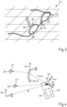
- the Fig. 1 shows as a scene 10 a table 12 with a tablecloth 14, on which a pair of glasses 16 with a frame 18 and with a left and right lens 20, 22 accommodated in it, along with other objects 24 in the form of a knife, a bottle, a cup and a book as well as a cigar.
- the scene 10 shown is time-invariant and contains as structure points 26 characteristic points of a pattern of the tablecloth 14 and the objects 24, which define a coordinate system 25 of the scene 10, as well as characteristic points of the spectacle frame 18 of the spectacles 16.
- the scene 10 is recorded using the camera 28 in an image capture device 30 designed as a smartphone in a variety of different recording positions 32, 34, 36, ... by a user holding the smartphone switched to video mode with one hand and moving it along a trajectory 38.
- the user thus records the scene 10 using the camera 28 of the image capture device 30 from different perspectives.
- the image capture device 30 contains a computer unit 40 for processing the recordings of the scene 10 recorded using the camera 28.
- the Fig. 2 is a section 42 of a first image of the scene 10 captured by the image capture device 30 from a first recording position 32 with images 26' of structural points 26.
- a further section 42 of a first image of the scene 10 with images 26' of structural points 26 captured by means of the image capture device 30 from a further recording position 36 different from the first recording position 32 is shown.
- a plurality of structural points 26 are each captured with an imaging beam path that passes through or does not pass through the first and/or the second spectacle lens 20, 22 in the spectacle frame 18 of the spectacles 16.
- images of the scene 10 which contain a section of the spectacle frame 18 defining a coordinate system 44 of the spectacle frame 18.
- the Fig. 4 shows the coordinate system 25 of the scene 10 and a coordinate system 46 of the image capture device 30 with a spectacle lens 20, 22. From the many captured images of the scene 10, the computer unit 40 in the image capture device 30 calculates the coordinates of the structure points 26 of a pattern 27 in the scene using a SLAM algorithm by means of a ray model in a coordinate system 46 referenced to the image capture device 30, which in turn is referenced to the coordinate system 25 of the scene 10 and the coordinate system 44 of the spectacle frame 18 of the spectacles 16.
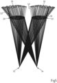
- the Fig. 5 shows a ray model of the glasses 16 with imaging beam paths guided into the camera 28 of the image capture device 30 with main rays 53, 53' for structure points 26 when the scene 10 is captured from two different recording positions 32, 34.
- a ray model not only requires knowledge of the positions of the image capture device 30 but also requires a three-dimensional model for the scene 10 as well as knowledge of the position of the Fig. 1 shown glasses 16 in the scene 10 and, in addition, also the information as to which structural points 26 in the scene 10 the image capture device 30 captures through the left lens 20 or the right lens 22 of the glasses 16.
- the position of each of these structural points 26 in the scene 10 in the coordinate system 46 of the image capture device 30 can be deduced from the intrinsic parameters of the image capture device as well as the location and position of an image capture device at the time of capturing an image.
- a main ray 53, 53' which passes through a lens 20, 22 of the glasses 16, is then calculated according to the position of the image capture device 30. From this and from the 3D coordinate of the point, a ray model is then obtained which reflects various viewing conditions of the same glasses 16 in the same scene 10 and which describes imaging rays which are deflected and which correspond to the various positions of an image capture device.
- An inverse approach is a reversal of the so-called forward calculation, in which the course of light rays through an optical system consisting of known optical interfaces and known refractive indices between the interfaces is calculated in an optical ray calculation, which is also known as ray tracing. Provided that the interfaces, their normals and the refractive indices are known, it is possible to calculate each light ray through the system unambiguously.
- an optical interface or refractive index is sought that matches a given number of light rays.
- the forward calculation is carried out using the area determined using the inverse approach and a comparison is then made of ray points in front of and/or behind the respective interface.
- the error size is then specifically minimized using an optimization process.
- pure optimization methods which can determine the minimum of an error function through parameter variations
- light path triangulation methods which can also be used in combination with an optimization method.
- the dioptric power of the lenses can be calculated, if their shape and refractive index are known, in particular by forward calculation of beams of rays.
- the vertex power of a lens can be determined, for example, by propagating a parallel beam of rays, the diameter of which is about 5 mm and thus corresponds to the size of the eye's pupil, through the lens in such a way that its main ray, ie its optical axis, leaves the lens perpendicularly on the eye side.
- the value of the vertex power is then the reciprocal of the distance from the surface of the lens from which the main ray emerges to the point of the smallest beam waist or extension of the beam of rays.
- the direction-dependent expansion of the beam of rays has two minima.
- the distance between these two minima and the surface of the lens describes the effect of the two main sections.
- the difference between these two main sections describes the cylindrical effect of the lens.
- the entire deflection of the main ray by the lens is to be regarded as the prismatic effect of the lens at the respective point.
- the so-called intrinsic camera calibration operator is used to convert pixel coordinates C of the camera 28 in the image capture device 30 to the beam vector of an imaging beam path. K .
- the camera calibration operator K can be determined, for example, from a recording of a special calibration pattern, e.g. a checkerboard pattern or a dot pattern, using the image capture device.
- a special calibration pattern e.g. a checkerboard pattern or a dot pattern
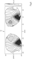
- Fig. 6 is a graph 52 to a based on the in the Fig. 5
- the distribution of the refractive power k(x,y) for the left and right lenses 20, 22 calculated from the ray model of the spectacles 16 shown can be seen.
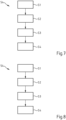
- the Fig. 7 is a flow chart 54 of the method described above for measuring a left and/or right spectacle lens 20, 22 in a pair of spectacles 16.
- a first step S1 at least a first image of a scene 10 with a plurality of structure points 26 and with a left and/or a right spectacle lens 20, 22 in a pair of spectacles 16 and with a section of the The spectacle frame 18 of the spectacles 16 is captured by means of an image capture device 30 with an imaging beam path for structural points 26 which passes through the first and/or the second spectacle lens 20, 22 of the spectacles 16.
- step S2 following step S1, at least two further images of the scene 10 without the first and/or the second spectacle lens 20, 22 of the spectacles 16 with the structural points 26 depicted in the first image are then captured by means of the image capture device 30.
- a step S3 the coordinates of the stationary, time-invariant structure points 26 in the coordinate system 25 of the scene 10 referenced to the coordinate system 46 of the image capture device 30 in the different recording positions are then calculated from the at least two further images of the scene 10 by means of image evaluation.
- step S4 the refractive power distribution k(x, y) is then determined for at least one section of the left spectacle lens 20 in the coordinate system 44 of the spectacle frame 18 referenced to the coordinate system 25 of the scene 10 and/or the refractive power distribution k(x, y) is determined for at least one section of the right spectacle lens 22 in a coordinate system 25 of the scene 10 referenced to the coordinate system 44 of the spectacle frame 18 from the coordinates of the stationary, time-invariant structural points 26 and the image of the structural points 26 in the at least one first image of the scene 10.
- the Fig. 8 shows a flow chart 54 for an alternative method to the method described above for measuring a left and/or right spectacle lens 20, 22 in a pair of spectacles 16, which is described below with reference to the Fig. 9 to Fig. 12 described.
- a first step S1 as in the Fig. 9 to be seen, by means of an image capture device 30 a sequence of first images of a time-invariant scene 10 with a plurality of structure points 26 and with a left and/or a right spectacle lens 20, 22 in a pair of spectacles 16 is captured together with a portion of the spectacle frame 18 which has a Fig. 4 shown coordinate system 44 of the spectacle frame 18 is defined.
- the capture of images of the scene 10 is carried out with imaging beam paths for structure points 26, which at least partially penetrate the first and/or the second spectacle lens 20, 22 of the spectacles 16 and are at least partially guided past the first and/or the second spectacle lens 20, 22 of the spectacles 16.
- step S2 following step S1, as in the Fig. 10
- a sequence of further images of the scene 10 with stationary, time-invariant structure points 26, but without the glasses 16, is captured. It should be noted that step S2 can also occur before step S1 or at the same time.
- a step S3 the coordinate system 25 of the scene 10 is referenced to the coordinate system 44 of the spectacle frame 18 and the coordinates of the structure points 26 in the coordinate system 25 of the scene 10 referenced to the coordinate system 46 of the image capture device 30 in the different recording positions are then calculated from the at least one further image of the scene 10 by means of image analysis.
- the refractive power distribution k(x,y) is determined for at least one section of the left spectacle lens 20 in the coordinate system 44 of the spectacle frame 18 referenced to the coordinate system 25 of the scene 10 and/or the refractive power distribution k(x,y) is determined for at least one section of the right spectacle lens 22 in the coordinate system 44 of the spectacle frame 18 from the coordinates of the structure points 26 and the image the structure points 26 in the at least one first image of the scene 10.
- the measurement of a left and/or right spectacle lens 20, 22 in a spectacle frame 18 is also possible by capturing images of a scene 10 in which a spectacle wearer is present with and without spectacles.
- a sequence of first images of a time-invariant scene 10 with a plurality of structure points 26 and with a left and/or a right spectacle lens 20, 22 in a spectacle frame 18 is captured together with a section of the spectacle frame 18 which defines a coordinate system 44 of the spectacle frame 18.
- the capture of images of the scene 10 takes place with imaging beam paths for structure points 26 which at least partially penetrate the first and/or the second spectacle lens 20, 22 of the spectacles 16 and which are at least partially guided past the first and/or the second spectacle lens 20, 22 of the spectacles 16.
- a sequence of further images of the scene 10 with structure points 26, but without the glasses 16, is recorded.
- the coordinates of the structure points 26 are then calculated in a coordinate system 25 of the scene 10 referenced to the coordinate system 46 of the image capture device 30 at different recording positions from the at least one further image of the scene 10 by means of image analysis and the coordinate system 25 of the scene 10 is referenced to the coordinate system 44 of the glasses frame 18.
- the refractive power distribution k(x,y) is then determined for at least one section of the left glasses lens 20 in the coordinate system 44 of the glasses frame 18 and/or the refractive power distribution k(x,y) is determined for at least one section of the right glasses lens 22 in the coordinate system 44 of the glasses frame 18 from the coordinates of the structure points 26 and the image of the Structural points 26 in the at least one first image of the scene 10 are determined.
- the computer unit of the image capture device 30 contains a program routine by means of which the position of the structure points 26 is calculated by evaluating neighborhood relationships, in particular distances between the structure points 26 in the scene 10, in a coordinate system 25 of the scene 10 referenced to the coordinate system 44 of the spectacle frame 18.
- the invention relates to a method for measuring the local refractive power or the refractive power distribution of a left and/or a right spectacle lens 20, 22 in a spectacle frame 18.
- at least a first image of a scene 10 with at least one structural point 26 and with a left and/or a right spectacle lens 20, 22 in a spectacle frame 18 is captured by means of an image capture device 30 from at least a first recording position 32 with at least one imaging beam path for structural points 26, which passes through the first and/or the second spectacle lens 20, 22 in the spectacle frame 18.
- At least two further images of the scene 10 are captured without the first and/or the second spectacle lens 20, 22 of the spectacle frame 18 or without the spectacle frame containing the left and/or the right spectacle lens with the structural points 26 depicted in the first image are captured by means of the image capture device 30 from at least two different recording positions 32, 34, 36, one of which can be identical to the first recording position, and the coordinates of the structural points 26 are calculated in a coordinate system 25 from the at least two further images of the scene 10 by means of image analysis, or at least two further images of the scene 10 with the left and/or the right spectacle lens 20, 22 are captured by means of an image capture device 30 from at least two further recording positions different from the first recording position with at least one imaging beam path for the structural points 26 depicted in the first image, which does not pass through the first and/or the second spectacle lens 20, 22 of the spectacle frame 18, in order to then calculate a refractive power distribution k(x,y) for at least a portion of the left spectacle lens 20 in a coordinate system 25 of the scene 10 referenced
Landscapes
- Physics & Mathematics (AREA)
- General Physics & Mathematics (AREA)
- Engineering & Computer Science (AREA)
- Ophthalmology & Optometry (AREA)
- Health & Medical Sciences (AREA)
- Optics & Photonics (AREA)
- Chemical & Material Sciences (AREA)
- Analytical Chemistry (AREA)
- Computer Vision & Pattern Recognition (AREA)
- Theoretical Computer Science (AREA)
- Geometry (AREA)
- General Health & Medical Sciences (AREA)
- Eyeglasses (AREA)
- Testing Of Optical Devices Or Fibers (AREA)
- Eye Examination Apparatus (AREA)
- Investigating Or Analysing Materials By Optical Means (AREA)
Claims (15)
- Procédé de mesure de la vergence locale d'un verre de lunettes gauche et/ou d'un verre de lunettes droit (20, 22) dans une monture de lunettes (18), ledit procédé comprenantune étape de capture d'au moins une première reproduction d'une scène (10) à l'aide de nombreux points de structure (26) et d'un verre de lunettes gauche et/ou d'un verre de lunettes droit (20, 22) dans la monture de lunettes (18) au moyen d'au moins un dispositif de capture d'images (30) à partir d'au moins une première position de réception (32) avec au moins un trajet de faisceau de reproduction pour chacun de ces points de structure (26) qui traverse le verre de lunettes gauche et/ou le verre de lunettes droit (20, 22),une étape de capture d'au moins deux autres reproductions de la scène (10) sans le verre de lunettes gauche et/ou le verre de lunettes droit (20, 22) de la monture de lunettes (18) ou sans la monture de lunettes (18) contenant le verre de lunettes gauche et/ou le verre de lunettes droit (20, 22) avec les points de structure (26) reproduits sur la première reproduction au moyen de l'au moins un dispositif de capture d'images (30) à partir d'au moins deux positions de réception différentes (32, 34, 36) dont l'une peut être identique à la première position de réception (32) ; etune étape de calcul des coordonnées des points de structure (26) dans un système de coordonnées (25) à partir des au moins deux autres reproductions de la scène (10) au moyen d'une évaluation d'image par triangulation,caractérisé parune étape de détermination d'une vergence locale du verre de lunettes gauche (20) et/ou du verre de lunettes droit (22) à partir des coordonnées des points de structure (26) et de l'image des points de structure (26) dans au moins une première reproduction de la scène (10) au moyen d'une approche inverse dans laquelle les surfaces limites optiques du verre de lunettes gauche et/ou du verre de lunettes droit (20, 22) sont calculées à partir des trajets de faisceau de reproduction pour les points de structure (26) par minimisation de la taille d'un défaut par variation de la surface limite à déterminer à chaque fois, la taille du défaut par rapport la surface limite étant déterminée par comparaison de points de faisceau devant et derrière la surface limite par traçage de rayons.
- Procédé de mesure de la vergence locale d'un verre de lunettes gauche et/ou d'un verre de lunettes droit (20, 22) dans une monture de lunettes (18), ledit procédé comprenantune étape de capture d'au moins une première reproduction d'une scène (10) à l'aide de nombreux points de structure (26) et d'un verre de lunettes gauche et/ou d'un verre de lunettes droit (20, 22) dans la monture de lunettes (18) au moyen d'au moins un dispositif de capture d'images (30) à partir d'au moins une première position de réception (32) avec pour chacun de ces points de structure (26) au moins un trajet de faisceau de reproduction qui traverse le verre de lunettes gauche et/ou le verre de lunettes droit (20, 22),une étape de capture d'au moins deux autres reproductions de la scène (10) à l'aide du verre de lunettes gauche et/ou du verre de lunettes droit (20, 22) au moyen d'au moins un dispositif de capture d'images (30) à partir d'au moins deux autres positions de réception (34, 36) différentes de la première position de réception (32) comportant chacune au moins un trajet de faisceau de reproduction pour les points de structure (26) capturés dans la première reproduction qui ne traversent pas le verre de lunettes gauche et le verre de lunettes droit (20, 22) de la monture de lunettes (18) ; etune étape de calcul des coordonnées des points de structure (26) à partir d'au moins deux autres reproductions de la scène (10) au moyen d'une évaluation d'image par triangulationcaractérisé parune étape de détermination d'une vergence locale du verre de lunettes gauche (20) et/ou du verre de lunettes droit (22) à partir des coordonnées des points de structure (26) et de l'image des points de structure (26) dans au moins une première reproduction de la scène (10) par une approche inverse dans laquelle les surfaces limites optiques du verre de lunettes gauche et/ou du verre de lunettes droit (20, 22) sont calculées à partir des trajets de faisceaux de reproduction pour les points de structure (26) par minimisation de la taille d'un défaut par variation de la surface limite à déterminer à chaque fois, la taille du défaut par rapport à la surface limite étant déterminée par comparaison de points de faisceau devant et derrière la surface limite par traçage de rayons.
- Procédé selon la revendication 1 ou 2, caractérisé par la capture d'un grand nombre de premières reproductions de la scène (10) et d'un grand nombre d'autres reproductions de la scène (10), les coordonnées des points de structure (26) dans le système de coordonnées (25) étant calculées à partir du grand nombre d'autres reproductions de la scène (10).
- Procédé selon l'une des revendications 1 à 3, caractérisé en ce que la scène (10) contient un œil gauche (48) et/ou un œil droit (50) d'un porteur de la monture de lunettes (18).
- Procédé selon la revendication 4, caractérisé en ce qu'un grand nombre de reproductions de la scène (10) sont capturées au moyen du dispositif de capture d'images (30) par déplacement du dispositif de capture d'images (30), l'œil gauche (48) et/ou l'œil droit (50) du porteur de la monture de lunettes (18) regardant le dispositif de capture d'images (30) déplacé et des trajets de faisceaux de visualisation pour différentes directions de visualisation de l'œil gauche (48) et/ou de l'œil droit (50) du porteur de la monture de lunettes (18) à travers le verre de lunettes gauche (20) et/ou le verre de lunettes droit (22) de la monture de lunettes (18) étant calculés à partir du grand nombre de reproductions alors capturées de la scène (10), et une vergence locale étant déterminée pour chaque direction de visualisation k(x, y) du verre de lunettes gauche (20) et/ou du verre de lunettes droit (22) .
- Procédé selon l'une des revendications 1 à 5, caractérisé en ce qu'un algorithme SLAM est utilisé pour calculer des paramètres intrinsèques de l'au moins un dispositif de capture d'images (30).
- Procédé selon la revendication 6, caractérisé par des paramètres intrinsèques du groupe comprenant la distance focale, le centre d'image, des paramètres de cisaillement, des paramètres d'échelle, des paramètres de distorsion.
- Procédé selon l'une des revendications 1 à 7, caractérisé en ce qu'un algorithme SLAM est utilisé pour calculer les coordonnées des points de structure (26) et/ou les positions de réception (32, 34, 36) de l'au moins un dispositif de capture d'images (30) dans le système de coordonnées (25) ; et/ou en ce que les coordonnées d'au moins une partie des points de structure (26) dans la scène (10) sont invariantes ; et/ou en ce que les coordonnées des points de structure (26) sont calculées par évaluation des décalages entre les reproductions des points de structure (26) dans la scène (10) à partir de différentes positions de réception (32, 34, 36) dans un système de coordonnées (25) .
- Procédé selon l'une des revendications 1 à 8, caractérisé en ce qu'une évaluation des relations de voisinage entre les points de structure (26) dans la scène (10) permet de détecter un déplacement de points de structure (26) dans un repère (25) et les coordonnées de points de structure (26) déplacés dans une scène (10) ne sont pas prises en compte lors de la détermination d'une répartition de vergence k(x,y) pour au moins une portion du verre de lunettes droit (22) et/ou du verre de lunettes gauche (20).
- Procédé de mesure de la répartition de vergence k(x,y) d'un verre de lunettes gauche et/ou d'un verre de lunettes droit (20, 22) dans une monture de lunettes (18), procédé dans lequel une vergence locale du verre de lunettes gauche et/ou du verre de lunettes droit (20, 22) est mesurée en différents endroits du verre gauche et/ou droit (20, 22) selon l'une des revendications 1 à 9.
- Produit de programme d'ordinateur comprenant un programme d'ordinateur comprenant un code de programme destiné à réaliser toutes les étapes de procédé qui sont indiquées dans l'une des revendications 1 à 10, lorsque le programme d'ordinateur est chargé dans une unité informatique d'un dispositif selon la revendication 12 et/ou exécuté dans une unité informatique d'un dispositif selon la revendication 12.
- Dispositif de mesure de la vergence locale d'un verre de lunettes gauche et/ou d'un verre de lunettes droit (20, 22) dans une monture de lunettes (18) à l'aide d'un dispositif de capture d'image (30) et d'une unité informatique (40) dans laquelle est chargé un programme informatique comprenant un code de programme destiné à réaliser toutes les étapes de procédé qui sont indiquées dans l'une des revendications 1 à 9, ou de mesure de la répartition de vergence d'un verre de lunettes gauche et/ou d'un verre de lunettes droit (20, 22) dans une monture de lunettes (18) à l'aide d'un dispositif de capture d'images (30) et d'une unité informatique (40) dans laquelle est chargé un programme informatique comprenant un code de programme destiné à réaliser toutes les étapes de procédé qui sont indiquées dans la revendication 10.
- Dispositif selon la revendication 12 qui est conçu comme un Smartphone ou comme une tablette ou comme un appareil photo (28).
- Support de données lisible par ordinateur sur lequel est mémorisé le produit de programme d'ordinateur selon la revendication 11.
- Signal porteur de données qui transmet le programme d'ordinateur selon la revendication 11.
Applications Claiming Priority (3)
| Application Number | Priority Date | Filing Date | Title |
|---|---|---|---|
| EP19170715.7A EP3730919A1 (fr) | 2019-04-23 | 2019-04-23 | Procédé et dispositif de mesure de la force de rupture locale ou de la distribution de la force de rupture d'un verre de lunettes |
| PCT/EP2020/061238 WO2020216799A1 (fr) | 2019-04-23 | 2020-04-22 | Procédé et dispositif pour mesurer la puissance optique locale et/ou la répartition de puissance optique d'un verre de lunettes |
| EP20723300.8A EP3959497B1 (fr) | 2019-04-23 | 2020-04-22 | Procédé et dispositif de mesure de la force de rupture locale ou de la distribution de la force de rupture d'un verre de lunettes |
Related Parent Applications (2)
| Application Number | Title | Priority Date | Filing Date |
|---|---|---|---|
| EP20723300.8A Division EP3959497B1 (fr) | 2019-04-23 | 2020-04-22 | Procédé et dispositif de mesure de la force de rupture locale ou de la distribution de la force de rupture d'un verre de lunettes |
| EP20723300.8A Division-Into EP3959497B1 (fr) | 2019-04-23 | 2020-04-22 | Procédé et dispositif de mesure de la force de rupture locale ou de la distribution de la force de rupture d'un verre de lunettes |
Publications (3)
| Publication Number | Publication Date |
|---|---|
| EP3982102A1 EP3982102A1 (fr) | 2022-04-13 |
| EP3982102B1 true EP3982102B1 (fr) | 2024-10-16 |
| EP3982102C0 EP3982102C0 (fr) | 2024-10-16 |
Family
ID=66251606
Family Applications (3)
| Application Number | Title | Priority Date | Filing Date |
|---|---|---|---|
| EP19170715.7A Withdrawn EP3730919A1 (fr) | 2019-04-23 | 2019-04-23 | Procédé et dispositif de mesure de la force de rupture locale ou de la distribution de la force de rupture d'un verre de lunettes |
| EP20723300.8A Active EP3959497B1 (fr) | 2019-04-23 | 2020-04-22 | Procédé et dispositif de mesure de la force de rupture locale ou de la distribution de la force de rupture d'un verre de lunettes |
| EP21209645.7A Active EP3982102B1 (fr) | 2019-04-23 | 2020-04-22 | Procédé et dispositif pour mesurer la puissance optique locale et/ou la répartition de puissance optique d'un verre de lunettes |
Family Applications Before (2)
| Application Number | Title | Priority Date | Filing Date |
|---|---|---|---|
| EP19170715.7A Withdrawn EP3730919A1 (fr) | 2019-04-23 | 2019-04-23 | Procédé et dispositif de mesure de la force de rupture locale ou de la distribution de la force de rupture d'un verre de lunettes |
| EP20723300.8A Active EP3959497B1 (fr) | 2019-04-23 | 2020-04-22 | Procédé et dispositif de mesure de la force de rupture locale ou de la distribution de la force de rupture d'un verre de lunettes |
Country Status (8)
| Country | Link |
|---|---|
| US (1) | US11982878B2 (fr) |
| EP (3) | EP3730919A1 (fr) |
| JP (1) | JP7126031B2 (fr) |
| KR (1) | KR102444768B1 (fr) |
| CN (1) | CN113711003B (fr) |
| ES (1) | ES2933452T3 (fr) |
| IL (1) | IL287469B2 (fr) |
| WO (1) | WO2020216799A1 (fr) |
Families Citing this family (6)
| Publication number | Priority date | Publication date | Assignee | Title |
|---|---|---|---|---|
| EP3730998A1 (fr) | 2019-04-23 | 2020-10-28 | Carl Zeiss Vision International GmbH | Détermination d'au moins un paramètre optique d'un verre de lunettes |
| EP3730918A1 (fr) | 2019-04-23 | 2020-10-28 | Carl Zeiss Vision International GmbH | Procédé et dispositif de mesure de la force de rupture locale et / ou de la répartition de la force de rupture d'un verre de lunettes |
| EP3730037A1 (fr) | 2019-04-23 | 2020-10-28 | Carl Zeiss Vision International GmbH | Détermination d'une erreur de réfection d'un il |
| US12247826B2 (en) * | 2021-06-11 | 2025-03-11 | Optinno BV | Spectacle lens shape measurement method |
| CN114112328A (zh) * | 2021-12-13 | 2022-03-01 | 上海理工大学 | 一种镜片屈光度测量装置及方法 |
| EP4443219A1 (fr) * | 2023-04-03 | 2024-10-09 | Carl Zeiss Vision International GmbH | Appareil et procédé adaptés pour balayer une monture de lunettes |
Family Cites Families (18)
| Publication number | Priority date | Publication date | Assignee | Title |
|---|---|---|---|---|
| US3880525A (en) * | 1974-05-08 | 1975-04-29 | American Optical Corp | Method and apparatus for determining the refractive characteristics of a lens |
| JPS5690233A (en) * | 1979-12-24 | 1981-07-22 | Asahi Optical Co Ltd | Automatic lens meter |
| JP4086429B2 (ja) * | 1998-10-12 | 2008-05-14 | Hoya株式会社 | 眼鏡レンズの評価方法及び評価装置 |
| KR20010061557A (ko) * | 1999-12-28 | 2001-07-07 | 박종섭 | 반도체 메모리 소자 및 그 제조 방법 |
| KR20060093596A (ko) * | 2005-02-22 | 2006-08-25 | 엘지전자 주식회사 | 이동단말기의 디옵터 측정 방법 |
| JP5107359B2 (ja) * | 2007-08-31 | 2012-12-26 | Hoya株式会社 | 累進屈折力レンズの評価方法および評価装置、並びに累進屈折力レンズの製造方法 |
| FR2984565A1 (fr) * | 2011-12-19 | 2013-06-21 | Thomson Licensing | Procede et dispositif d'estimation de la puissance optique des lentilles de verres correcteurs d'une paire de lunettes portee par un spectateur. |
| JP6307805B2 (ja) | 2013-07-24 | 2018-04-11 | 富士通株式会社 | 画像処理装置、電子機器、眼鏡特性判定方法および眼鏡特性判定プログラム |
| US9910505B2 (en) * | 2014-06-17 | 2018-03-06 | Amazon Technologies, Inc. | Motion control for managing content |
| US10019140B1 (en) * | 2014-06-26 | 2018-07-10 | Amazon Technologies, Inc. | One-handed zoom |
| DE102014116665B4 (de) * | 2014-09-22 | 2024-07-25 | Carl Zeiss Ag | Verfahren und Vorrichtungen zur Bestimmung der Augenrefraktion |
| KR101528132B1 (ko) * | 2014-11-13 | 2015-06-12 | 윤철주 | 모바일 디바이스를 이용한 안경렌즈의 도수 측정방법 |
| CN204514573U (zh) * | 2015-01-15 | 2015-07-29 | 中山大学中山眼科中心 | 一种镜片周边有效屈光力的测量装置 |
| DE102015211879B4 (de) * | 2015-06-25 | 2018-10-18 | Carl Zeiss Ag | Vermessen von individuellen Daten einer Brille |
| WO2017134275A1 (fr) | 2016-02-05 | 2017-08-10 | Eidgenossische Technische Hochschule Zurich | Procédés et systèmes permettant de déterminer un axe optique et/ou des propriétés physiques d'une lentille, et leur utilisation dans l'imagerie virtuelle et des visiocasques |
| EP3730036A1 (fr) | 2019-04-23 | 2020-10-28 | Carl Zeiss Vision International GmbH | Détermination d'une erreur de réfection d'un il |
| EP3730037A1 (fr) | 2019-04-23 | 2020-10-28 | Carl Zeiss Vision International GmbH | Détermination d'une erreur de réfection d'un il |
| EP3730918A1 (fr) | 2019-04-23 | 2020-10-28 | Carl Zeiss Vision International GmbH | Procédé et dispositif de mesure de la force de rupture locale et / ou de la répartition de la force de rupture d'un verre de lunettes |
-
2019
- 2019-04-23 EP EP19170715.7A patent/EP3730919A1/fr not_active Withdrawn
-
2020
- 2020-04-22 JP JP2021563134A patent/JP7126031B2/ja active Active
- 2020-04-22 CN CN202080030607.8A patent/CN113711003B/zh active Active
- 2020-04-22 EP EP20723300.8A patent/EP3959497B1/fr active Active
- 2020-04-22 KR KR1020217037544A patent/KR102444768B1/ko active Active
- 2020-04-22 WO PCT/EP2020/061238 patent/WO2020216799A1/fr not_active Ceased
- 2020-04-22 IL IL287469A patent/IL287469B2/en unknown
- 2020-04-22 EP EP21209645.7A patent/EP3982102B1/fr active Active
- 2020-04-22 ES ES20723300T patent/ES2933452T3/es active Active
-
2021
- 2021-10-19 US US17/504,905 patent/US11982878B2/en active Active
Also Published As
| Publication number | Publication date |
|---|---|
| IL287469B2 (en) | 2023-10-01 |
| BR112021021170A2 (pt) | 2021-12-14 |
| KR102444768B1 (ko) | 2022-09-19 |
| WO2020216799A1 (fr) | 2020-10-29 |
| EP3959497A1 (fr) | 2022-03-02 |
| EP3730919A1 (fr) | 2020-10-28 |
| IL287469B1 (en) | 2023-06-01 |
| US11982878B2 (en) | 2024-05-14 |
| US20220035183A1 (en) | 2022-02-03 |
| JP2022528575A (ja) | 2022-06-14 |
| CN113711003B (zh) | 2024-03-08 |
| KR20210147075A (ko) | 2021-12-06 |
| EP3982102C0 (fr) | 2024-10-16 |
| IL287469A (en) | 2021-12-01 |
| ES2933452T3 (es) | 2023-02-09 |
| EP3959497B1 (fr) | 2022-11-09 |
| JP7126031B2 (ja) | 2022-08-25 |
| CN113711003A (zh) | 2021-11-26 |
| EP3982102A1 (fr) | 2022-04-13 |
Similar Documents
| Publication | Publication Date | Title |
|---|---|---|
| EP3982102B1 (fr) | Procédé et dispositif pour mesurer la puissance optique locale et/ou la répartition de puissance optique d'un verre de lunettes | |
| EP3542211B2 (fr) | Procédé et dispositif ainsi que programme informatique destinés à déterminer une représentation d'un bord de verre de lunettes | |
| EP3924710B1 (fr) | Procédé et dispositif de mesure de la force de rupture locale et / ou de la répartition de la force de rupture d'un verre de lunettes | |
| EP3956721B1 (fr) | Détermination d'au moins un paramètre optique d'un verre de lunettes | |
| EP3702832B1 (fr) | Procédé, dispositifs et programme informatique de détermination d'un point visuel proche | |
| EP3183616B1 (fr) | Détermination de données d'utilisateur avec prise en compte de données d'image d'une monture de lunettes choisie | |
| EP3671324A1 (fr) | Procédé, dispositif et programme informatique destinés à l'adaptation virtuelle d'une monture de lunettes | |
| DE60117432T2 (de) | Verfahren und Gerät zur Simulation eines optischen Okularsystems | |
| DE102016106121A1 (de) | Verfahren und Vorrichtung zum Bestimmen von Parametern zur Brillenanpassung | |
| EP3256036B1 (fr) | Dispositif et procédé de détermination de distance et/ou de centrage à l'aide des réflexions cornéennes | |
| EP3869150B1 (fr) | Méthode et appareil pour mesurer la cornée d'un sujet | |
| EP3210071B1 (fr) | Dispositif et procédé de détermination de paramètres optiques | |
| EP4143628B1 (fr) | Procédé mis en oeuvre par ordinateur de détermination des paramètres de centrage pour terminaux mobiles, terminal mobile et programme informatique | |
| EP3735891A2 (fr) | Procédé mis en uvre par ordinateur destiné à la détection d'un sommet de la cornée | |
| EP3195052A1 (fr) | Procédé de détermination précise de paramètres optiques d'un sujet pour ajuster des lunettes au sujet et système de centrage vidéo immobile | |
| DE102019212653A1 (de) | Computerimplementiertes Verfahren zum Aufnehmen einer Blickrichtung eines Auges eines Brillenträgers sowie Brille |
Legal Events
| Date | Code | Title | Description |
|---|---|---|---|
| PUAI | Public reference made under article 153(3) epc to a published international application that has entered the european phase |
Free format text: ORIGINAL CODE: 0009012 |
|
| STAA | Information on the status of an ep patent application or granted ep patent |
Free format text: STATUS: THE APPLICATION HAS BEEN PUBLISHED |
|
| AC | Divisional application: reference to earlier application |
Ref document number: 3959497 Country of ref document: EP Kind code of ref document: P |
|
| AK | Designated contracting states |
Kind code of ref document: A1 Designated state(s): AL AT BE BG CH CY CZ DE DK EE ES FI FR GB GR HR HU IE IS IT LI LT LU LV MC MK MT NL NO PL PT RO RS SE SI SK SM TR |
|
| STAA | Information on the status of an ep patent application or granted ep patent |
Free format text: STATUS: REQUEST FOR EXAMINATION WAS MADE |
|
| 17P | Request for examination filed |
Effective date: 20220812 |
|
| RBV | Designated contracting states (corrected) |
Designated state(s): AL AT BE BG CH CY CZ DE DK EE ES FI FR GB GR HR HU IE IS IT LI LT LU LV MC MK MT NL NO PL PT RO RS SE SI SK SM TR |
|
| GRAP | Despatch of communication of intention to grant a patent |
Free format text: ORIGINAL CODE: EPIDOSNIGR1 |
|
| STAA | Information on the status of an ep patent application or granted ep patent |
Free format text: STATUS: GRANT OF PATENT IS INTENDED |
|
| RIC1 | Information provided on ipc code assigned before grant |
Ipc: G02C 7/06 20060101ALN20240425BHEP Ipc: G02C 13/00 20060101ALI20240425BHEP Ipc: G01M 11/02 20060101AFI20240425BHEP |
|
| RIC1 | Information provided on ipc code assigned before grant |
Ipc: G02C 7/06 20060101ALN20240502BHEP Ipc: G02C 13/00 20060101ALI20240502BHEP Ipc: G01M 11/02 20060101AFI20240502BHEP |
|
| INTG | Intention to grant announced |
Effective date: 20240521 |
|
| GRAS | Grant fee paid |
Free format text: ORIGINAL CODE: EPIDOSNIGR3 |
|
| GRAA | (expected) grant |
Free format text: ORIGINAL CODE: 0009210 |
|
| STAA | Information on the status of an ep patent application or granted ep patent |
Free format text: STATUS: THE PATENT HAS BEEN GRANTED |
|
| AC | Divisional application: reference to earlier application |
Ref document number: 3959497 Country of ref document: EP Kind code of ref document: P |
|
| AK | Designated contracting states |
Kind code of ref document: B1 Designated state(s): AL AT BE BG CH CY CZ DE DK EE ES FI FR GB GR HR HU IE IS IT LI LT LU LV MC MK MT NL NO PL PT RO RS SE SI SK SM TR |
|
| REG | Reference to a national code |
Ref country code: GB Ref legal event code: FG4D Free format text: NOT ENGLISH |
|
| REG | Reference to a national code |
Ref country code: CH Ref legal event code: EP |
|
| REG | Reference to a national code |
Ref country code: IE Ref legal event code: FG4D Free format text: LANGUAGE OF EP DOCUMENT: GERMAN |
|
| REG | Reference to a national code |
Ref country code: DE Ref legal event code: R096 Ref document number: 502020009532 Country of ref document: DE |
|
| U01 | Request for unitary effect filed |
Effective date: 20241025 |
|
| U07 | Unitary effect registered |
Designated state(s): AT BE BG DE DK EE FI FR IT LT LU LV MT NL PT RO SE SI Effective date: 20241107 |
|
| PG25 | Lapsed in a contracting state [announced via postgrant information from national office to epo] |
Ref country code: IS Free format text: LAPSE BECAUSE OF FAILURE TO SUBMIT A TRANSLATION OF THE DESCRIPTION OR TO PAY THE FEE WITHIN THE PRESCRIBED TIME-LIMIT Effective date: 20250216 Ref country code: HR Free format text: LAPSE BECAUSE OF FAILURE TO SUBMIT A TRANSLATION OF THE DESCRIPTION OR TO PAY THE FEE WITHIN THE PRESCRIBED TIME-LIMIT Effective date: 20241016 |
|
| PG25 | Lapsed in a contracting state [announced via postgrant information from national office to epo] |
Ref country code: ES Free format text: LAPSE BECAUSE OF FAILURE TO SUBMIT A TRANSLATION OF THE DESCRIPTION OR TO PAY THE FEE WITHIN THE PRESCRIBED TIME-LIMIT Effective date: 20241016 |
|
| PG25 | Lapsed in a contracting state [announced via postgrant information from national office to epo] |
Ref country code: NO Free format text: LAPSE BECAUSE OF FAILURE TO SUBMIT A TRANSLATION OF THE DESCRIPTION OR TO PAY THE FEE WITHIN THE PRESCRIBED TIME-LIMIT Effective date: 20250116 |
|
| PG25 | Lapsed in a contracting state [announced via postgrant information from national office to epo] |
Ref country code: GR Free format text: LAPSE BECAUSE OF FAILURE TO SUBMIT A TRANSLATION OF THE DESCRIPTION OR TO PAY THE FEE WITHIN THE PRESCRIBED TIME-LIMIT Effective date: 20250117 |
|
| PG25 | Lapsed in a contracting state [announced via postgrant information from national office to epo] |
Ref country code: PL Free format text: LAPSE BECAUSE OF FAILURE TO SUBMIT A TRANSLATION OF THE DESCRIPTION OR TO PAY THE FEE WITHIN THE PRESCRIBED TIME-LIMIT Effective date: 20241016 |
|
| PG25 | Lapsed in a contracting state [announced via postgrant information from national office to epo] |
Ref country code: RS Free format text: LAPSE BECAUSE OF FAILURE TO SUBMIT A TRANSLATION OF THE DESCRIPTION OR TO PAY THE FEE WITHIN THE PRESCRIBED TIME-LIMIT Effective date: 20250116 |
|
| U20 | Renewal fee for the european patent with unitary effect paid |
Year of fee payment: 6 Effective date: 20250425 |
|
| PG25 | Lapsed in a contracting state [announced via postgrant information from national office to epo] |
Ref country code: SM Free format text: LAPSE BECAUSE OF FAILURE TO SUBMIT A TRANSLATION OF THE DESCRIPTION OR TO PAY THE FEE WITHIN THE PRESCRIBED TIME-LIMIT Effective date: 20241016 |
|
| PG25 | Lapsed in a contracting state [announced via postgrant information from national office to epo] |
Ref country code: SK Free format text: LAPSE BECAUSE OF FAILURE TO SUBMIT A TRANSLATION OF THE DESCRIPTION OR TO PAY THE FEE WITHIN THE PRESCRIBED TIME-LIMIT Effective date: 20241016 |
|
| PG25 | Lapsed in a contracting state [announced via postgrant information from national office to epo] |
Ref country code: CZ Free format text: LAPSE BECAUSE OF FAILURE TO SUBMIT A TRANSLATION OF THE DESCRIPTION OR TO PAY THE FEE WITHIN THE PRESCRIBED TIME-LIMIT Effective date: 20241016 |
|
| PLBE | No opposition filed within time limit |
Free format text: ORIGINAL CODE: 0009261 |
|
| STAA | Information on the status of an ep patent application or granted ep patent |
Free format text: STATUS: NO OPPOSITION FILED WITHIN TIME LIMIT |
|
| 26N | No opposition filed |
Effective date: 20250717 |
|
| REG | Reference to a national code |
Ref country code: CH Ref legal event code: H13 Free format text: ST27 STATUS EVENT CODE: U-0-0-H10-H13 (AS PROVIDED BY THE NATIONAL OFFICE) Effective date: 20251125 |