EP3981981B1 - Rotor blade for a wind turbine, wind turbine and method for designing a rotor blade - Google Patents
Rotor blade for a wind turbine, wind turbine and method for designing a rotor blade Download PDFInfo
- Publication number
- EP3981981B1 EP3981981B1 EP21201104.3A EP21201104A EP3981981B1 EP 3981981 B1 EP3981981 B1 EP 3981981B1 EP 21201104 A EP21201104 A EP 21201104A EP 3981981 B1 EP3981981 B1 EP 3981981B1
- Authority
- EP
- European Patent Office
- Prior art keywords
- profile
- trailing edge
- region
- pressure side
- arrangement
- Prior art date
- Legal status (The legal status is an assumption and is not a legal conclusion. Google has not performed a legal analysis and makes no representation as to the accuracy of the status listed.)
- Active
Links
Images


Classifications
-
- F—MECHANICAL ENGINEERING; LIGHTING; HEATING; WEAPONS; BLASTING
- F03—MACHINES OR ENGINES FOR LIQUIDS; WIND, SPRING, OR WEIGHT MOTORS; PRODUCING MECHANICAL POWER OR A REACTIVE PROPULSIVE THRUST, NOT OTHERWISE PROVIDED FOR
- F03D—WIND MOTORS
- F03D1/00—Wind motors with rotation axis substantially parallel to the air flow entering the rotor
- F03D1/06—Rotors
- F03D1/0608—Rotors characterised by their aerodynamic shape
- F03D1/0633—Rotors characterised by their aerodynamic shape of the blades
- F03D1/0641—Rotors characterised by their aerodynamic shape of the blades of the section profile of the blades, i.e. aerofoil profile
-
- F—MECHANICAL ENGINEERING; LIGHTING; HEATING; WEAPONS; BLASTING
- F03—MACHINES OR ENGINES FOR LIQUIDS; WIND, SPRING, OR WEIGHT MOTORS; PRODUCING MECHANICAL POWER OR A REACTIVE PROPULSIVE THRUST, NOT OTHERWISE PROVIDED FOR
- F03D—WIND MOTORS
- F03D1/00—Wind motors with rotation axis substantially parallel to the air flow entering the rotor
- F03D1/06—Rotors
- F03D1/0608—Rotors characterised by their aerodynamic shape
- F03D1/0633—Rotors characterised by their aerodynamic shape of the blades
-
- F—MECHANICAL ENGINEERING; LIGHTING; HEATING; WEAPONS; BLASTING
- F05—INDEXING SCHEMES RELATING TO ENGINES OR PUMPS IN VARIOUS SUBCLASSES OF CLASSES F01-F04
- F05B—INDEXING SCHEME RELATING TO WIND, SPRING, WEIGHT, INERTIA OR LIKE MOTORS, TO MACHINES OR ENGINES FOR LIQUIDS COVERED BY SUBCLASSES F03B, F03D AND F03G
- F05B2230/00—Manufacture
- F05B2230/50—Building or constructing in particular ways
-
- F—MECHANICAL ENGINEERING; LIGHTING; HEATING; WEAPONS; BLASTING
- F05—INDEXING SCHEMES RELATING TO ENGINES OR PUMPS IN VARIOUS SUBCLASSES OF CLASSES F01-F04
- F05B—INDEXING SCHEME RELATING TO WIND, SPRING, WEIGHT, INERTIA OR LIKE MOTORS, TO MACHINES OR ENGINES FOR LIQUIDS COVERED BY SUBCLASSES F03B, F03D AND F03G
- F05B2240/00—Components
- F05B2240/20—Rotors
- F05B2240/30—Characteristics of rotor blades, i.e. of any element transforming dynamic fluid energy to or from rotational energy and being attached to a rotor
- F05B2240/301—Cross-section characteristics
-
- F—MECHANICAL ENGINEERING; LIGHTING; HEATING; WEAPONS; BLASTING
- F05—INDEXING SCHEMES RELATING TO ENGINES OR PUMPS IN VARIOUS SUBCLASSES OF CLASSES F01-F04
- F05B—INDEXING SCHEME RELATING TO WIND, SPRING, WEIGHT, INERTIA OR LIKE MOTORS, TO MACHINES OR ENGINES FOR LIQUIDS COVERED BY SUBCLASSES F03B, F03D AND F03G
- F05B2240/00—Components
- F05B2240/20—Rotors
- F05B2240/30—Characteristics of rotor blades, i.e. of any element transforming dynamic fluid energy to or from rotational energy and being attached to a rotor
- F05B2240/304—Details of the trailing edge
-
- F—MECHANICAL ENGINEERING; LIGHTING; HEATING; WEAPONS; BLASTING
- F05—INDEXING SCHEMES RELATING TO ENGINES OR PUMPS IN VARIOUS SUBCLASSES OF CLASSES F01-F04
- F05B—INDEXING SCHEME RELATING TO WIND, SPRING, WEIGHT, INERTIA OR LIKE MOTORS, TO MACHINES OR ENGINES FOR LIQUIDS COVERED BY SUBCLASSES F03B, F03D AND F03G
- F05B2240/00—Components
- F05B2240/20—Rotors
- F05B2240/30—Characteristics of rotor blades, i.e. of any element transforming dynamic fluid energy to or from rotational energy and being attached to a rotor
- F05B2240/305—Flaps, slats or spoilers
- F05B2240/3052—Flaps, slats or spoilers adjustable
-
- F—MECHANICAL ENGINEERING; LIGHTING; HEATING; WEAPONS; BLASTING
- F05—INDEXING SCHEMES RELATING TO ENGINES OR PUMPS IN VARIOUS SUBCLASSES OF CLASSES F01-F04
- F05B—INDEXING SCHEME RELATING TO WIND, SPRING, WEIGHT, INERTIA OR LIKE MOTORS, TO MACHINES OR ENGINES FOR LIQUIDS COVERED BY SUBCLASSES F03B, F03D AND F03G
- F05B2250/00—Geometry
- F05B2250/70—Shape
- F05B2250/71—Shape curved
- F05B2250/711—Shape curved convex
-
- Y—GENERAL TAGGING OF NEW TECHNOLOGICAL DEVELOPMENTS; GENERAL TAGGING OF CROSS-SECTIONAL TECHNOLOGIES SPANNING OVER SEVERAL SECTIONS OF THE IPC; TECHNICAL SUBJECTS COVERED BY FORMER USPC CROSS-REFERENCE ART COLLECTIONS [XRACs] AND DIGESTS
- Y02—TECHNOLOGIES OR APPLICATIONS FOR MITIGATION OR ADAPTATION AGAINST CLIMATE CHANGE
- Y02E—REDUCTION OF GREENHOUSE GAS [GHG] EMISSIONS, RELATED TO ENERGY GENERATION, TRANSMISSION OR DISTRIBUTION
- Y02E10/00—Energy generation through renewable energy sources
- Y02E10/70—Wind energy
- Y02E10/72—Wind turbines with rotation axis in wind direction
Definitions
- the invention relates to a rotor blade for a wind turbine, a rotor for a wind turbine and a method for designing a rotor blade.
- Wind turbines have a rotor with at least one, two or more rotor blades, preferably three rotor blades, and are designed to generate mechanical rotational energy from kinetic wind energy and from this electrical energy.
- Such wind turbines are generally known and usually comprise a nacelle on which the rotor is arranged and a tower on which the nacelle with the rotor is arranged so as to be rotatable about a substantially vertically aligned axis.
- Wind turbines are usually designed as so-called horizontal axis wind turbines, which comprise a rotor with a substantially horizontal axis, the rotor blades of which rotate in a plane substantially perpendicular to the wind.
- Such horizontal axis wind turbines use the aerodynamic principle of lift to convert the kinetic wind energy into mechanical rotational energy.
- the profile of a rotor blade forms a suction side and a pressure side, so that when moving air flows around the profile, a negative pressure is created on the suction side compared to the pressure side.
- the resulting pressure difference between the pressure side and the suction side leads to an aerodynamic lift.
- the lift depends, for example, on the angle of attack of the rotor blades.
- Known rotor blades are disadvantageous in that the air flow, particularly on the suction side, breaks off and a so-called "dead water area" with a separated flow forms. Particularly at larger angles of attack, the flow can no longer lie smoothly against the profile of a rotor blade and breaks off.
- the dead water area reduces the lift of the rotor blade and slows the rotor blade down by increasing its resistance. This reduces the efficiency of the rotor and thus also the yield of a wind turbine.
- Such rotor blades are particularly disadvantageous in that unwanted vibrations often occur at high wind speeds.
- a well-known dynamic instability of a rotor blade is flutter, a combined bending and torsional vibration. Flutter, i.e. in particular a mutual excitation of air forces, elastic forces and mass forces, can occur when the rotor blade is stimulated to oscillate. Such conditions are particularly dangerous because vibrations can accumulate as more and more energy is absorbed from the flow around it, which can, for example, damage the rotor blades.
- a rotor speed of the wind turbine above which there is a risk that the rotor blades tend to flutter should therefore generally be far enough outside the usual operating limits. In particular, with rotor blades becoming larger and lighter in the future, the risk of the rotor blade fluttering also increases at lower wind speeds.
- wind turbines are increasingly being designed in such a way that they have a rotor capacity of less than 300 W/m 2. This generally means that more full-load operating time can be achieved with reduced generator costs and reduced system loads.
- this design means that even at lower wind speeds, the power generated in the inner rotor blade area has to be partially destroyed in the outer area in order to be able to reduce the torque on the generator.
- the energy stored in a rotor current tube for The available wind power can be significantly greater, particularly in this operating state, than the power that can be dissipated via the generator. For example, it is known to destroy excess power by pitching the rotor blades. However, this can lead to flow separation at the blade tip, which can in turn lead to undesirable vibrations and, in particular, fluttering of the rotor blade.
- the wind turbine In order to avoid the above-mentioned disadvantageous operating conditions, the wind turbine must be switched off at relatively low wind speeds, in particular from a wind speed of 15 m/s or 20 m/s or 25 m/s.
- this earlier onset of storm control results in significant yield losses.
- German Patent and Trademark Office has searched the following prior art in the priority application for the present application: DE 10 2008 052 858 A1 , DE 10 2013 202 666 A1 , DE 10 2019 113 085 A1 , DE 20 2016 101 461 U1 , US 8 944 775 B2 , US 2008/0 240 923 A1 , US 2019/0 024 627 A1 , EP 1 944 505 A1 , WO 2007/115 861 A1 , WO 2009/068 719 A1 .
- the document CN 106050566 A further discloses a rotor blade having a jet flow device for carrying out active flow control with the jet flow device.
- the active flow control can generate a jet flow at the trailing edge, which is blunt in shape. This is intended to improve the aerodynamic efficiency of the rotor blade.
- this object is achieved by a rotor blade for a wind turbine, which extends in the longitudinal direction with a profile profile from a blade connection to a blade tip, wherein the profile profile contains at least one profile, comprising: a suction side and a pressure side, a relative profile thickness of more than 25%, a profile chord that extends between a leading edge and a trailing edge of the profile and has a length defining the profile depth, a skeleton line that runs at least partially below the profile chord, a convex region extending on the suction side starting from the trailing edge and a convex region extending on the pressure side starting from the trailing edge, wherein the convex region on the pressure side defines a rounded transition region of the pressure side to the trailing edge.
- the invention is based on the knowledge that undesirable vibrations and in particular fluttering of the rotor blade at high wind speeds are particularly due to large negative angles of attack at the rotor blade tip, which occur when at very high wind speeds, in particular at wind speeds above a wind speed at which the nominal power is reached, preferably at a wind speed of more than 15 m/s, a power generated in the inner rotor blade area has to be reduced or even partially destroyed in the outer area in order to be able to reduce the torque on the generator.
- the wind power available in a rotor power tube is therefore preferably significantly greater in this operating state than the power that can be dissipated via the generator.
- the excess power can be reduced or destroyed in particular by pitching the rotor blades and can lead to flow separation at the blade tip at high wind speeds. This flow separation can stimulate the undesirable vibrations and in particular the fluttering of the rotor blade.
- a rotor blade is provided with at least one profile which has a convex region starting from the trailing edge on both the suction side and the pressure side.
- a further advantage of the present solution is that the defined rounding of the transition area allows lift coefficients to be adjusted as required.
- the geometry of the rotor blade can be designed differently along the length of the rotor blade as required.
- the advantage here is that the geometry of individual profiles can be adjusted depending on the average annual wind speed.
- Another advantage is that the proposed solution can increase the overall efficiency of a wind turbine and thus in particular the annual yield.
- the production effort for such profiles and/or rotor blades as well as the production costs can be significantly reduced.
- the profile can be demolded much more easily than known flatback profiles.
- material can be saved in the production of such profiles and/or rotor blades and thus material costs can be reduced. This can also reduce the overall weight of the rotor blade.
- the rotor blade extends in particular in the longitudinal direction in the direction of a rotor blade length as well as in the direction of a rotor blade depth and a rotor blade thickness.
- the rotor blade In the direction of the rotor blade length, the rotor blade extends between the blade connection and the blade tip.
- the rotor blade depth is in particular aligned essentially orthogonally to the rotor blade length and extends between the leading edge and the Trailing edge.
- the rotor blade depth is aligned substantially parallel to a direction of flow of the rotor blade.
- the rotor blade extends in the direction of the rotor blade thickness substantially orthogonal to the direction of the rotor blade length and the rotor blade depth.
- the rotor blade depth and the rotor blade thickness define an aerodynamic profile in particular at substantially every position along the rotor blade length.
- the trailing edge can preferably have a suction-side trailing edge, also referred to as the suction-side trailing edge, and a pressure-side trailing edge, also referred to as the pressure-side trailing edge.
- the suction-side trailing edge and the pressure-side trailing edge can in particular be spaced apart from one another, so-called flatback profile, i.e. a profile with a flat trailing edge.
- the rotor blade in particular can have a specific trailing edge height at its rear end, i.e. at the trailing edge, and therefore essentially do not taper.
- a position, preferably a midpoint, between the suction-side trailing edge and the pressure-side trailing edge can then be used as the trailing edge to determine the profile depth.
- the profile can preferably have a closed trailing edge.
- the profile chord can preferably run from the leading edge to a point at which the profile converges, which is referred to as the trailing edge.
- the pressure-side, rounded transition region can extend to the suction-side trailing edge and in particular describe a convex end to the pressure side.
- the leading edge can preferably be a point on the profile nose that is furthest away from the trailing edge.
- the suction side of the rotor blade can in particular correspond to a surface of the rotor blade that generates lift when the wind turbine is in operation and thus drives the rotation of a rotor to which the rotor blade is attached when air flows around it.
- the pressure side can in particular be opposite the suction side.
- the profile of the rotor blade can have a number of profiles, also known as profile sections, which define the outer contour of the rotor blade.
- a rotor blade usually comprises a number of different profiles. The profiles are intended to enable an essentially aerodynamically optimal flow pattern at the various radius positions of a rotor blade.
- a skeleton line also referred to as a profile center line, camber line or curvature line, can be understood in particular as a connecting line of the circle centers inscribed in the profile.
- the skeleton line can preferably be defined as a line comprising the centers between the suction side and the pressure side perpendicular to an X coordinate of the profile or the profile chord.
- a relative profile thickness can preferably be understood as a maximum thickness of the profile perpendicular to the profile chord in relation to the profile chord length.
- a relative profile thickness of at least 45% can preferably be provided.
- the rotor blade in particular the profile with the rounded transition region of the pressure side to the trailing edge, can be used in particular when profile sections with large relative profile thicknesses, in particular of more than 25%, are used and an adjustment of lift coefficients is necessary or at least desirable.
- the profiles can be used particularly advantageously and economically in a hub section and/or a middle section of rotor blades of a wind turbine.
- the use of the profiles is not limited to use in the hub section and/or the middle section of rotor blades of a wind turbine.
- the rotor blade can preferably comprise an inner section adjacent to the blade connection and an outer section adjacent to the blade tip.
- the profile can be provided in the inner section.
- the outer section can extend between 80% and 100% of a relative rotor blade length.
- the inner section can extend between 0% and 80% of a relative rotor blade length.
- the inner section can preferably comprise the hub section and the middle section, wherein the hub section adjoins the blade connection and the middle section adjoins the hub section and the outer section, which can also be referred to in particular as the tip section.
- the profile is preferably provided at least partially in the central section and/or the hub section.
- the hub section can extend between 0% and 30% of the relative rotor blade length and the central section between 30% and 80% of the relative blade length.
- the rounded transition region can preferably have a radius.
- the radius can preferably have any size.
- the rounded transition region can have different radii.
- the radius or radii or at least one radius of the radii can have at least 5% of the profile chord length.
- the suction-side trailing edge can be designed as a sharp trailing edge with a radius equal to zero or approximately zero.
- the convex region on the suction side and/or the convex region on the pressure side can extend from the trailing edge towards the leading edge with an extension of a maximum of 1% of the length of the profile chord, preferably from a maximum of 5% to a maximum of 30% of the length of the profile chord, preferably up to a maximum of 40% of the length.
- a particularly preferred embodiment is characterized in that an arrangement for aerodynamic flow control is arranged on the rounded transition region, wherein the arrangement is preferably designed as a Gurney flap or a spreading flap.
- the arrangement can be designed as an air outlet, for example. Air flowing out of the air outlet can in particular influence the flow aerodynamically.
- the inventors have discovered that a loss of lift caused by the rounding of the transition area can be reduced or completely compensated for by the arrangement for aerodynamic flow control at this transition area.
- the arrangement does not significantly affect drag compared to a conventional flatback profile.
- This preferred embodiment is particularly advantageous in that the profile varies with regard to the lift performance and the rotor blade can be designed depending on requirements, in particular depending on the average annual wind speed.
- a further advantage of this design is that the production effort for a rotor blade with a high lift potential can be reduced. Furthermore, the need for complex production techniques, such as the use of foam inserts or separately manufactured molded elements, can be eliminated.
- a preferred development of the rotor blade is characterized in that the arrangement is arranged at an angle greater than 90 ° to a local desired flow direction, in particular greater than 100 ° to a local desired flow direction, at the rounded transition region.
- the arrangement preferably the Gurney flap or the spreading flap, can extend from a surface of the pressure side at an angle greater than 90 ° to the local desired flow direction, in particular greater than 100 ° to the local desired flow direction.
- the air outlet can be arranged on the surface of the pressure side in such a way that there is an angle greater than 90°, in particular greater than 100°, between the local desired flow direction and the direction of the escaping air.
- This design ensures cost-optimized production of the rotor blades.
- Another advantage is that the arrangement enables an adjustment of the height profile in order to achieve a site-specific lift distribution on the rotor blade. These site-specific rotor blade adjustments make it possible, for example, to increase the annual energy yield or to mitigate certain site-specific load cases, thereby enabling the operation of certain wind turbines at locations that would otherwise be impossible due to excessive loads.
- a local flow direction can be characterized in particular by a sum vector of the wind speed and the speed of the rotor blade tip.
- a change in wind speed at a constant rotor speed and constant angle of attack of the rotor blade leads to a change in the local flow direction and thus also in the angle of attack between the flow direction and the profile chord. This can in particular cause a change in the lift force acting on the rotor blade and thus ultimately a change in the efficiency of the rotor.
- a local target flow direction can be set and/or kept approximately constant by turning the rotor blades and the resulting change in the angle of attack.
- the arrangement has a length between 0.1% and 40% of the profile depth, wherein preferably the relative profile thickness of the profile is a maximum of 30% and the length of the arrangement is a maximum of 10% of the profile depth or is greater than 30% and the length of the arrangement is a maximum of 40% of the profile depth.
- the length can extend from the surface of the pressure side to an outer contour edge of the arrangement.
- the length and in particular the outer contour edge can also be defined by escaping air, for example in the case of an air outlet.
- a distance between the outer contour edge of the arrangement and the suction-side trailing edge can be at least 0.1% to 40% of a maximum profile thickness established between the suction side and the pressure side.
- a length of the arrangement of a first profile, which has a first distance from the blade root can be greater than a length of the arrangement of a second profile, which has a second distance from the blade root, wherein the second distance is greater than the first distance.
- the length of the arrangement of a profile in the inner section, in particular the hub section can be between 10% and 40% of the maximum profile thickness that occurs between the suction side and the pressure side.
- the length of the arrangement of a profile in the middle section and/or the outer section can be between 0.1 and 5%.
- the radius or radii of the rounded transition region can be between 0% and 100% of the distance between the outer contour edge of the arrangement and the suction-side trailing edge.
- an imaginary connecting line between the outer contour edge of the arrangement and the suction-side trailing edge can preferably be aligned substantially orthogonal to the desired flow direction.
- This imaginary connecting line can correspond in particular to a blunt trailing edge of a known flatback profile.
- the imaginary connecting line between the outer contour edge of the arrangement and the suction-side trailing edge can be aligned at an angle of substantially more than 90°, in particular between 90° and 120°, to the desired flow direction.
- the arrangement can in particular protrude beyond a contour of a known flatback profile. This can in particular result in higher drag and higher moment coefficients as well as an increase in lift and an increase in the effective area on the pressure side. Overall, this can in particular achieve a reduction in the total drag and/or an optimization of the lift.
- Such profiles can be formed in particular in the profile course at a transition to a circular cylinder at the rotor blade root, since the highest possible lift coefficients are aimed for here in particular.
- This additional lift can be used to additionally stabilize the rotor blade, preferably in operating conditions with large angles of attack, in order to avoid flow separation.
- Such large angles of attack can occur in particular in the upper partial load range, when the nominal power has not yet been reached, but the optimal tip speed ratio has already been exceeded due to limitations in the blade tip speed.
- a further preferred development of the rotor blade is characterized in that the arrangement is moved from a first position in which the distance between the outer contour edge of the arrangement and the suction-side trailing edge is at least 10% of the maximum profile thickness established between the suction side and the pressure side, towards a second position which describes a lift-reduced configuration, in which reduces the distance between the outer contour edge of the arrangement and the suction-side trailing edge.
- the arrangement can preferably be pivoted about an inner contour edge which is arranged on the pressure side.
- the arrangement can be retractable and extendable, wherein preferably the retracted position describes the second position, wherein preferably the arrangement in the second position is recessed inwards relative to a plane which is congruent with a pressure-side surface.
- the arrangement in the first position can protrude outwards relative to this plane.
- the arrangement for buoyancy control is designed to be actively controllable.
- the arrangement can comprise an actuator that can be controlled by a control unit in order to move the arrangement from the first position to the second position and from the second position to the first position and/or to any other position between the first position and the second position.
- This preferred embodiment is particularly advantageous in that the profile can be varied greatly in terms of its lift performance depending on requirements.
- This design allows the power generated locally, in particular by the rotor blade root and the blade center area, to be reduced in a targeted manner, preferably at high wind speeds, in order to be able to avoid large negative angles of attack locally, in particular at the rotor blade tip. This makes it possible to shut down the Wind turbines can be shifted to higher wind speeds, thus increasing yields, particularly in windy locations.
- the local lift coefficient on profiles can be adapted to the respective operating state of the wind turbine over a wide range. This means that an optimized induction factor distribution can be achieved for each operating state, which has a particularly significant effect on increasing performance.
- the arrangement can be designed as a Gurney flap, in particular as a hinge, elastic flap or linear element with actuator or as an inflatable contour, and can be actively controlled.
- the skeleton line runs under the profile chord and/or has a mathematically positive curvature in a region in which the skeleton line is defined by the convex region extending from the trailing edge on the pressure side and the convex region extending from the trailing edge on the suction side.
- the convex region on the pressure side may have a stronger convexity than the convex region on the suction side.
- the skeleton line can run steeply in an end region in the direction of the suction side.
- gradients of tangents in the end region can be steeper than gradients of tangents in front of the end region.
- the end region can extend from the trailing edge in the direction of the leading edge with an extent of less than 50% of the trailing edge region, in particular less than 30% of the trailing edge region, in particular less than 10% of the trailing edge region.
- the skeleton line can have an S-bend in the region of the trailing edge.
- the skeleton line can preferably have the mathematically positive curvature, in particular in a region starting from the trailing edge towards the leading edge with a Extension between 20% and 0% of the length of the chord, in particular between 10% and 0% of the length of the chord.
- the skeleton line has a rear local minimum lying below the profile chord in the region in which the skeleton line is defined by the convex region extending from the trailing edge on the pressure side and the convex region extending from the trailing edge on the suction side, and/or if the skeleton line has a front local minimum lying below the profile chord in a region in which the skeleton line is defined by a convex region extending from the leading edge on the pressure side and the convex region extending from the leading edge on the suction side.
- the minimum or minima relate in particular to a position relative to the profile, with the front edge being understood in particular as the front end and the rear edge as the rear end of the profile.
- the front local minimum can be located further in the direction of the front edge than the rear local minimum.
- the convex region on the suction side and/or the convex region on the pressure side can extend from the leading edge towards the trailing edge with an extent between 0% and 60% of the length of the profile chord.
- the skeleton line has the front local minimum and the rear local minimum, wherein the pressure side has a concave region in a region between the convex region extending from the front edge and the convex region extending from the rear edge, wherein preferably the rear local minimum or the front local minimum is an absolute minimum.
- the entire skeleton line runs under the profile chord. Accordingly, the skeleton line can preferably run in an area between the profile chord and the pressure side.
- the trailing edge is a closed trailing edge or a flat trailing edge, wherein a height of the flat trailing edge is less than 40%, preferably less than 20%, preferably less than 10%, of the maximum profile thickness established between the suction side and the pressure side, and/or optionally approximately 50% of the distance between the outer contour edge of the arrangement and the suction-side trailing edge.
- the profile has a thickness allowance which defines a ratio of a distance of a maximum profile thickness from the leading edge in the direction of the profile chord and the length of the profile chord, wherein the ratio is preferably less than 40%.
- the object mentioned above is achieved by a wind turbine with at least one rotor blade, as described above.
- the object mentioned at the outset is achieved by a method for designing a rotor blade which extends in the longitudinal direction with a profile profile from a blade connection to a blade tip, with the steps: selecting at least one profile for the profile profile, comprising a suction side and a pressure side, a relative profile thickness of more than 25%, a profile chord which extends between a leading edge and a trailing edge of the profile and has a length defining a profile depth, a skeleton line which runs at least partially under the profile chord, a convex region extending on the suction side from the trailing edge and a convex region extending on the pressure side from the trailing edge, wherein the convex region on the pressure side defines a rounded transition region from the pressure side to the trailing edge, preferably adjusting a height profile of a profile by arranging an arrangement for influencing aerodynamic flow on the rounded transition region, wherein the selection of the at least one profile and/or the adjustment of the height profile is based at
- a particularly preferred embodiment provides that the height of the profile is adjusted in such a way that a distance between an outer contour edge of the Arrangement and a suction-side trailing edge is at least 10% of a maximum profile thickness that occurs between the suction side and the pressure side, preferably further comprising the step: adjusting a local lift coefficient, in particular to an operating state of a wind turbine, by aligning the arrangement by moving the arrangement from a first position in which the distance between an outer contour edge of the arrangement and a suction-side trailing edge is at least 10% of the maximum profile thickness that occurs between the suction side and the pressure side, in the direction of a second position which describes a lift-reduced configuration in which the distance between the outer contour edge of the arrangement and the suction-side trailing edge is reduced and/or moving the arrangement from a second position which describes a lift-reduced configuration in which the distance between the outer contour edge of the arrangement and the suction-side trailing edge is less than 10% of the maximum profile thickness that occurs between the suction side and the pressure side, in the
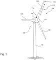
- Figure 1 shows a schematic, three-dimensional view of a wind turbine 100.
- the wind turbine 100 has a tower 102 and a nacelle 104 on the tower 102.
- An aerodynamic rotor 106 with three rotor blades 108 and a spinner 110 is provided on the nacelle 104.
- At least one of the rotor blades has a profile with at least one profile, which has a convex region on the suction side and one on the pressure side extending from the trailing edge (in Figure 1 not recognizable), such as in Figures 2 to 7 is shown.
- the aerodynamic rotor 106 is set into a rotary motion by the wind and thus also rotates an electrodynamic rotor or runner of a generator, which is directly or indirectly coupled to the aerodynamic rotor 106.
- the electrical generator is arranged in the nacelle 104 and generates electrical energy.
- the rotor blades 108 shown extend in particular in the longitudinal direction 112 with a profile course from a blade connection 114 to a blade tip 116.
- the profile course comprises in particular at least one profile (in Figure 1 not shown), as described below.
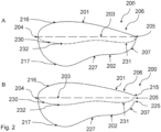
- the Figures 2A to 4B each show a profile 200 with a suction side 201 and a pressure side 202 opposite the suction side 201 in different design variants.
- the profile 200 preferably has a relative profile thickness, i.e. in particular a maximum thickness of the profile perpendicular to the profile chord 203 in relation to the profile chord length, of more than 25%.
- the profile chord length is defined here as the length of the profile chord 203, which extends from the front edge 204 to the rear edge 205.
- a convex region 206 extends on the suction side 201 as well as a convex region 207 on the pressure side.
- the pressure side 202 and/or the suction side 201 can in particular have further convex regions and/or concave regions.
- the pressure side 202 can, starting from the front edge 204, have a first convex region 217, a concave region 227 and a second convex region 207 adjacent to the concave region 227.
- Such a course of the pressure side 202 is shown, for example, in the Figures 2A to 3B
- the pressure side 202 and/or the suction side 201 can be designed to be convex overall.
- a profile 200 is shown with a closed trailing edge 205, in which the profile chord 203 preferably runs from the leading edge 204 to a point at which the profile converges, which is referred to as the trailing edge 205.
- Figure 2B shows a trailing edge with a pressure-side trailing edge 225 and a suction-side trailing edge 215 spaced apart from it. A midpoint between the suction-side trailing edge 215 and the pressure-side trailing edge 225 is used as the trailing edge 205 for determining the profile depth.
- the profiles 200 shown each have a skeleton line 230 which runs under the profile chord 203.
- the skeleton line 230 has a rear local minimum 231 in the region in which it is defined by the convex region 207 extending from the trailing edge 205 on the pressure side 202 and the convex region 206 extending from the trailing edge 205 on the suction side 201.
- the rear local minimum 231 lies under the profile chord 203.
- the skeleton line 230 has a front local minimum 232 in a region in which the skeleton line 230 is defined by a convex region 217 extending from the leading edge 204 on the pressure side 202 and the convex region 216 extending from the leading edge 204 on the suction side 201.
- the front local minimum 232 is also below the profile chord 203.
- the front local minimum 232 is the absolute minimum in the examples shown here.
- the pressure side 202 has a concave region 227 in a region between the convex region 207 and the convex region 217.
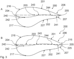
- a profile 200 is shown with a closed trailing edge 205, in which the profile chord 203 preferably runs from the leading edge 204 to a point at which the profile converges, which is referred to as the trailing edge 205.
- Figure 3B shows a trailing edge with a pressure-side trailing edge 225 and a suction-side trailing edge 215 spaced apart from it.
- the trailing edge 205 for determining the Profile depth is determined by a midpoint between the suction side trailing edge 215 and the pressure side trailing edge 225.
- the Figures 3A and 3B The profiles 200 shown each have a skeleton line 240 which runs under the profile chord 203.
- the skeleton line 240 has a rear local minimum 241 in the region in which it is defined by the convex region 207 extending from the trailing edge 205 on the pressure side 202 and the convex region 206 extending from the trailing edge 205 on the suction side 201.
- the rear local minimum 241 lies under the profile chord 203.
- the skeleton line 240 has a front local minimum 242 in a region in which the skeleton line 240 is defined by a convex region 217 extending from the leading edge 204 on the pressure side 202 and the convex region 216 extending from the leading edge 204 on the suction side 201.
- the front local minimum 242 is also below the profile chord 203.
- the pressure side 202 has a concave region 227 in a region between the convex region 216 and the convex region 217.
- the front local minimum 242 is the absolute minimum in the examples shown here.
- the skeleton line 240 runs at least partially over the profile chord 203.
- the skeleton line 240 intersects the profile chord 203 between the rear local minimum 241 and the front local minimum 242 at a first intersection point 243 and at a second intersection point 244.
- the skeleton line 240 runs between the first intersection point 243 and the second intersection point 244 over the profile chord 203.
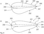
- a profile 200 is shown with a closed trailing edge 205, in which the profile chord 203 preferably runs from the leading edge 204 to a point at which the profile converges, which is referred to as the trailing edge 205.
- Figure 4B shows a trailing edge with a pressure-side trailing edge 225 and a suction-side trailing edge 215 spaced apart from it. A center point between the suction-side trailing edge 215 and the pressure-side trailing edge 225 is used as the trailing edge 205 for determining the profile depth.
- the Figures 4A and 4B The profiles shown each have a skeleton line 250 which runs under the profile chord 203 and has a mathematically positive curvature
- the positive curvature is defined by the substantially convex pressure side 202 and the substantially convex suction side 201.
- the skeleton line 250 has a single minimum 251 which lies below the profile chord 203.
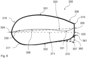
- a profile 300 with a suction side 301 and a pressure side 302 opposite the suction side 301 is shown.
- the profile 300 preferably has a relative profile thickness of more than 25%.
- the profile chord 303 extends from the leading edge 304 to the trailing edge 305.
- a convex region 306 extends on the suction side 301 and a convex region 307 extends on the pressure side.
- the convex region 307 defines a rounded transition region on which an arrangement 360 for aerodynamic flow control is arranged.
- a Gurney flap is shown schematically as an example of the arrangement 360.
- the profile 300 has a trailing edge with a pressure-side trailing edge 325 and a suction-side trailing edge 315 spaced apart therefrom. A midpoint between the suction-side trailing edge 315 and the pressure-side trailing edge 325 is used as the trailing edge 305 for determining the profile depth.
- the Figures 5 and 6 The profiles 300 shown each have a skeleton line 330 which runs partially under the profile chord 303.
- the skeleton line 330 has a minimum 331 in the area in which it is defined by the convex region 307 extending from the trailing edge 305 on the pressure side 302 and the convex region 306 extending from the trailing edge 305 on the suction side 301. The minimum 331 lies below the profile chord 303.
- the skeleton line 330 has a maximum 308 which lies above the profile chord 303 in a region in which the skeleton line 330 is defined by a convex region 317 extending on the pressure side 302 from the leading edge 304 and the convex region 316 extending on the suction side 301 from the leading edge 304.
- the arrangement 360 is in a first position in which the outer contour edge 361 of the arrangement 360 is spaced from the pressure-side trailing edge 325 and thus also from the suction-side trailing edge 315. This distance can in particular be at least 10% of the maximum profile thickness that occurs between the suction side 301 and the pressure side 302.
- the arrangement 360 is in a second position, which describes a lift-reduced configuration in which the distance between the outer contour edge 361 of the arrangement 360 and the pressure-side trailing edge 325 and thus also the suction-side trailing edge 315 is reduced.
- the arrangement 360 can be moved from the first position to the second position.
- the arrangement 360 can be designed to be actively controllable for buoyancy control.
- the Figures 5 and 6 show that the arrangement 360 is designed to adjust a height profile of the profile 300.
- the outer contour edge 361 can function as a pressure-side trailing edge.
- the height profile of the profile can correspond approximately to a height profile of a flatback profile 370 with a corresponding profile chord 371.
- a trailing edge defining this profile chord 371 coincides with the pressure-side trailing edge 325.
- This trailing edge is a midpoint between the outer contour edge 361 of the arrangement 360 and the suction-side trailing edge 315.
- a profile 300 is shown with a suction side 301 and a pressure side 302 opposite the suction side 301.
- the profile 300 preferably has a relative profile thickness of more than 25%.
- the profile chord 303 extends from the leading edge 304 to the closed trailing edge 305. Starting from the trailing edge 305, a convex region 306 extends on the suction side 301 and a convex region 307 extends on the pressure side.
- the profile has a skeleton line 330 which runs partially under the profile chord 303.
- the skeleton line 330 has a minimum 331 in the area in which it is defined by the convex region 307 extending from the trailing edge 305 on the pressure side 302 and the convex region 306 extending from the trailing edge 305 on the suction side 301.
- the minimum 331 lies below the profile chord 303.
- the skeleton line 330 has a maximum 308 which lies above the profile chord 303 in a region in which the skeleton line 330 is defined by a convex region 317 extending on the pressure side 302 from the leading edge 304 and the convex region 316 extending on the suction side 301 from the leading edge 304.
- the convex region 307 defines a rounded transition region on which an arrangement 380 for aerodynamic flow control is arranged.
- a Gurney flap is shown schematically as an example of the arrangement 380.
- the arrangement 380 can in particular be permanently installed or actively controllable in order to adapt a height profile of the profile 300 and to function as a pressure-side trailing edge.
- the arrangement 380 has a greater length.
- the length of an arrangement 360 can be greater the larger the radius of the rounding of the transition region.
- the height profile of the profile 300 can be optimally adjusted to approximately correspond to a height profile of a flatback profile 390 with a corresponding profile chord 391.
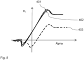
- FIG 8 A diagram is shown which shows the lift coefficients C L of different profiles as a function of the angle of attack ⁇ .
- Three graphs 401, 402, 403 can be seen, with graph 401 showing the lift coefficients of a profile with a rounded transition area on the pressure side to the trailing edge with an arrangement for aerodynamic flow control, graph 402 showing the lift coefficients of a flatback profile and graph 403 showing the lift coefficients of a profile with a rounded transition area on the pressure side to the trailing edge without an arrangement for aerodynamic flow control.
- Rotor blades with such profiles and wind turbines with these rotor blades have various advantages.
- the above-described embodiments allow lift coefficients to be adjusted as required.
- Another advantage is that the proposed solution can increase the overall efficiency of a wind turbine and, in particular, the annual yield.
- both the effort and costs of production can be reduced while saving weight.
Landscapes
- Engineering & Computer Science (AREA)
- Physics & Mathematics (AREA)
- Fluid Mechanics (AREA)
- Life Sciences & Earth Sciences (AREA)
- Sustainable Development (AREA)
- Sustainable Energy (AREA)
- Chemical & Material Sciences (AREA)
- Combustion & Propulsion (AREA)
- Mechanical Engineering (AREA)
- General Engineering & Computer Science (AREA)
- Wind Motors (AREA)
Description
Die Erfindung betrifft ein Rotorblatt für eine Windenergieanlage, einen Rotor für eine Windenergieanlage sowie ein Verfahren zur Auslegung eines Rotorblatts.The invention relates to a rotor blade for a wind turbine, a rotor for a wind turbine and a method for designing a rotor blade.
Windenergieanlagen weisen einen Rotor mit mindestens einem, zwei oder mehreren Rotorblättern, vorzugsweise drei Rotorblättern, auf und sind ausgebildet, um aus kinetischer Windenergie mechanische Rotationsenergie und aus dieser elektrische Energie zu erzeugen. Derartige Windenergieanlagen sind allgemein bekannt und umfassen in der Regel eine Gondel, an der der Rotor angeordnet ist, und einen Turm, auf dem die Gondel mit dem Rotor um eine im Wesentlichen vertikal ausgerichtete Achse drehbar angeordnet ist.Wind turbines have a rotor with at least one, two or more rotor blades, preferably three rotor blades, and are designed to generate mechanical rotational energy from kinetic wind energy and from this electrical energy. Such wind turbines are generally known and usually comprise a nacelle on which the rotor is arranged and a tower on which the nacelle with the rotor is arranged so as to be rotatable about a substantially vertically aligned axis.
Windenergieanlagen sind in der Regel als sogenannte Horizontalachsen-Windenergieanlagen ausgebildet, die einen Rotor mit einer im Wesentlichen horizontalen Achse umfassen, dessen Rotorblätter sich in einer Ebene im Wesentlichen senkrecht zum Wind drehen. Derartige Horizontalachsen-Windenergieanlagen nutzen zur Wandlung der kinetischen Windenergie in die mechanische Rotationsenergie das aerodynamische Prinzip des Auftriebs. Hierbei bildet ein Profil eines Rotorblatts eine Saugseite und eine Druckseite aus, sodass bei Umströmung des Profils mit bewegter Luft auf der Saugseite gegenüber der Druckseite ein Unterdruck entsteht. Der daraus resultierende Druckunterschied zwischen der Druckseite und der Saugseite führt zu einem aerodynamischen Auftrieb. Der Auftrieb ist hierbei beispielsweise von einem Anstellwinkel der Rotorblätter abhängig.Wind turbines are usually designed as so-called horizontal axis wind turbines, which comprise a rotor with a substantially horizontal axis, the rotor blades of which rotate in a plane substantially perpendicular to the wind. Such horizontal axis wind turbines use the aerodynamic principle of lift to convert the kinetic wind energy into mechanical rotational energy. The profile of a rotor blade forms a suction side and a pressure side, so that when moving air flows around the profile, a negative pressure is created on the suction side compared to the pressure side. The resulting pressure difference between the pressure side and the suction side leads to an aerodynamic lift. The lift depends, for example, on the angle of attack of the rotor blades.
Bekannte Rotorblätter sind dahingehend nachteilig, dass die anliegende Luftströmung, insbesondere an einer Saugseite, abreißt und sich ein sogenanntes "Totwassergebiet" mit einer abgelösten Strömung bildet. Insbesondere bei größeren Anstellwinkeln kann die Strömung nicht mehr glatt an einem Profil eines Rotorblatts anliegen und reißt ab. Das Totwassergebiet mindert den Auftrieb des Rotorblatts und bremst das Rotorblatt ab, indem es dessen Widerstand erhöht. Dadurch wird ein Wirkungsgrad des Rotors und somit auch ein Ertrag einer Windenergieanlage reduziert.Known rotor blades are disadvantageous in that the air flow, particularly on the suction side, breaks off and a so-called "dead water area" with a separated flow forms. Particularly at larger angles of attack, the flow can no longer lie smoothly against the profile of a rotor blade and breaks off. The dead water area reduces the lift of the rotor blade and slows the rotor blade down by increasing its resistance. This reduces the efficiency of the rotor and thus also the yield of a wind turbine.
Zur Verbesserung der aerodynamischen Eigenschaften von Rotorblättern und zur Steigerung der Effizienz sind unterschiedliche Lösungen bekannt. Beispielsweise ist es bekannt, Rotorblätter mit einer flachen Hinterkante, sog. Flatback-Profile, insbesondere im Innenbereich zu verwenden. Zur Produktion derartig dicker Profile mit einer druckseitig und saugseitig scharfen, flachen Hinterkante werden in der Regel zusätzliche Schaumeinleger benötigt. Daher ist die Produktion konstruktiv sehr aufwändig und mit erhöhten Kosten, insbesondere mit zusätzlichen Materialkosten, hohen Personalkosten und Herstellungskosten, verbunden.Various solutions are known for improving the aerodynamic properties of rotor blades and increasing efficiency. For example, it is known to use rotor blades with a flat trailing edge, so-called flatback profiles, especially for interior use. To produce such thick profiles with a sharp, flat trailing edge on the pressure side and suction side, additional foam inserts are usually required. This means that production is very complex in terms of construction and involves increased costs, in particular additional material costs, high personnel costs and manufacturing costs.
Derartige Rotorblätter sind insbesondere dahingehend nachteilig, dass bei hohen Windgeschwindigkeiten oftmals unerwünschte Schwingungen auftreten. Eine bekannte dynamische Instabilität eines Rotorblatts stellt das Flattern, eine kombinierte Biege- und Torsionsschwingung, dar. Das Flattern, also insbesondere eine gegenseitige Anregung von Luftkräften, elastischen Kräften und Massekräften, kann entstehen, wenn das Rotorblatt zu einer oszillierenden Bewegung angeregt wird. Derartige Zustände sind insbesondere gefährlich, da sich Schwingungen aufaddieren können, indem immer mehr Energie aus einer Umströmung aufgenommen wird, wodurch beispielsweise die Rotorblätter Schaden nehmen können. Eine Rotordrehzahl der Windenergieanlage, oberhalb derer die Gefahr besteht, dass die Rotorblätter zum Flattern neigen, sollte daher in der Regel weit genug außerhalb üblicher Betriebsgrenzen liegen. Insbesondere bei in Zukunft größer und gleichzeitig leichter werdenden Rotorblättern steigt die Gefahr des Flatterns des Rotorblatts auch bei niedrigeren Windgeschwindigkeiten.Such rotor blades are particularly disadvantageous in that unwanted vibrations often occur at high wind speeds. A well-known dynamic instability of a rotor blade is flutter, a combined bending and torsional vibration. Flutter, i.e. in particular a mutual excitation of air forces, elastic forces and mass forces, can occur when the rotor blade is stimulated to oscillate. Such conditions are particularly dangerous because vibrations can accumulate as more and more energy is absorbed from the flow around it, which can, for example, damage the rotor blades. A rotor speed of the wind turbine above which there is a risk that the rotor blades tend to flutter should therefore generally be far enough outside the usual operating limits. In particular, with rotor blades becoming larger and lighter in the future, the risk of the rotor blade fluttering also increases at lower wind speeds.
Aus diesem Grund können die durch die Flatback-Profile erzielbaren Vorteile lediglich bei Windenergieanlagen mit relativ kleinem Rotordurchmesser bei großer Nennleistung, beispielsweise mit 3 MW Nennleistung und einer Rotorkapazität von mehr als 500 W/m2 oder mit 3 MW Nennleistung und einer Rotorkapazität von 374 W/m2 oder mit 4,2 MW Nennleistung und einer Rotorkapazität von 337 W/m2, wirtschaftlich genutzt werden.For this reason, the advantages achievable by the flatback profiles can only be economically exploited in wind turbines with a relatively small rotor diameter and a high rated power, for example with 3 MW rated power and a rotor capacity of more than 500 W/m 2 or with 3 MW rated power and a rotor capacity of 374 W/m 2 or with 4.2 MW rated power and a rotor capacity of 337 W/m 2 .
Zur Einsparung von Kosten werden jedoch Windenergieanlagen zunehmend insbesondere derart ausgelegt, dass diese eine Rotorkapazität von weniger als 300 W/m2 aufweisen. Dadurch kann in der Regel mehr Volllastbetriebszeit bei reduzierten Generatorkosten und reduzierten Anlagenlasten erzielt werden. Diese Auslegung führt jedoch insbesondere dazu, dass schon bei geringeren Windgeschwindigkeiten eine im inneren Rotorblattbereich erzeugte Leistung im äußeren Bereich teilweise wieder vernichtet werden muss, um das Drehmoment am Generator reduzieren zu können. Die in einer Rotorstromröhre zur Verfügung stehende Windleistung kann insbesondere in diesem Betriebszustand deutlich größer sein, als eine Leistung, die über den Generator abgeführt werden kann. Es ist beispielsweise bekannt, überschüssige Leistung durch Pitchen der Rotorblätter zu vernichten. Dadurch können jedoch insbesondere Strömungsablösungen an der Blattspitze entstehen, die wieder zu unerwünschten Schwingungen und insbesondere Flattern des Rotorblatts führen können.However, in order to save costs, wind turbines are increasingly being designed in such a way that they have a rotor capacity of less than 300 W/m 2. This generally means that more full-load operating time can be achieved with reduced generator costs and reduced system loads. However, this design means that even at lower wind speeds, the power generated in the inner rotor blade area has to be partially destroyed in the outer area in order to be able to reduce the torque on the generator. The energy stored in a rotor current tube for The available wind power can be significantly greater, particularly in this operating state, than the power that can be dissipated via the generator. For example, it is known to destroy excess power by pitching the rotor blades. However, this can lead to flow separation at the blade tip, which can in turn lead to undesirable vibrations and, in particular, fluttering of the rotor blade.
Zur Vermeidung vorstehend genannter nachteiliger Betriebszustände ist die Windenergieanlage insbesondere schon bei relativ geringen Windgeschwindigkeiten, insbesondere ab einer Windgeschwindigkeit von 15 m/s oder 20 m/s oder 25 m/s, abzuschalten. Durch diese früher einsetzende Sturmregelung treten jedoch signifikante Ertragsverluste auf.In order to avoid the above-mentioned disadvantageous operating conditions, the wind turbine must be switched off at relatively low wind speeds, in particular from a wind speed of 15 m/s or 20 m/s or 25 m/s. However, this earlier onset of storm control results in significant yield losses.
In der Luftfahrtbranche ist es beispielsweise bekannt, vorstehend genannte Nachteile durch eine Leistungsreduktion mittels einer Auftriebsreduktion oder einem signifikanten Widerstandsanstieg, insbesondere an der Blattwurzel und der Blattmitte, zu reduzieren oder verhindern. Bekannte Maßnahmen hierfür sind beispielsweise Bremsklappen, Wölbklappen, Spoiler und Split-Flaps. Nachteilig sind jedoch die technische Komplexität und der damit verbundene Wartungsaufwand. Aufgrund dieser Nachteile ist der Einsatz derartiger Maßnahmen bei Windenergieanlagen nicht wirtschaftlich.In the aviation industry, for example, it is known that the disadvantages mentioned above can be reduced or prevented by reducing power by reducing lift or by significantly increasing drag, particularly at the blade root and the middle of the blade. Known measures for this include air brakes, camber flaps, spoilers and split flaps. The disadvantages, however, are the technical complexity and the associated maintenance effort. Due to these disadvantages, the use of such measures in wind turbines is not economical.
Die existierenden Vorrichtungen zur Steigerung der Effizienz und/oder zur Vermeidung von unerwünschten Schwingungen und Flatterbewegungen bieten verschiedene Vorteile, jedoch sind weitere Verbesserungen wünschenswert.The existing devices to increase efficiency and/or prevent unwanted vibrations and flutter movements offer several advantages, but further improvements are desirable.
Das Deutsche Patent- und Markenamt hat in der Prioritätsanmeldung zu vorliegender Anmeldung folgenden Stand der Technik recherchiert:
Das Dokument
Die Erfindung wird durch die beigefügten Ansprüche definiert,The invention is defined by the appended claims,
Es ist daher eine Aufgabe der vorliegenden Erfindung, ein Rotorblatt für eine Windenergieanlage, eine Windenergieanlage und/oder ein Verfahren zur Auslegung eines Rotorblatts bereitzustellen, die einen oder mehrere der genannten Nachteile vermindern oder beseitigen. Es ist insbesondere eine Aufgabe der Erfindung, eine Lösung bereitzustellen, die Effizienz eines Rotorblatts einer Windenergieanlage für eine hohe Anlagenwirtschaftlichkeit weiter zu steigern und gleichzeitig Flatterbewegungen des Rotorblatts zu verhindern. Insbesondere ist es eine Aufgabe den Aufwand und die Komplexität der Produktion des Rotorblatts sowie die Produktionskosten zu reduzieren.It is therefore an object of the present invention to provide a rotor blade for a wind turbine, a wind turbine and/or a method for designing a rotor blade, which reduce or eliminate one or more of the disadvantages mentioned. It is in particular an object of the invention to provide a solution to further increase the efficiency of a rotor blade of a wind turbine for high system economics and at the same time prevent fluttering movements of the rotor blade. In particular, one task is to reduce the effort and complexity of producing the rotor blade as well as the production costs.
Gemäß einem ersten Aspekt wird diese Aufgabe gelöst durch ein Rotorblatt für eine Windenergieanlage, das sich in Längsrichtung mit einem Profilverlauf von einem Blattanschluss zu einer Blattspitze erstreckt, wobei der Profilverlauf zumindest ein Profil enthält, umfassend: eine Saugseite und eine Druckseite, eine relativen Profildicke von mehr als 25 %, eine Profilsehne, die sich zwischen einer Vorderkante und einer Hinterkante des Profils erstreckt und eine die Profiltiefe definierende Länge aufweist, eine Skelettlinie, die zumindest teilweise unterhalb der Profilsehne verläuft, einen sich auf der Saugseite ausgehend von der Hinterkante erstreckenden konvexen Bereich und einen sich auf der Druckseite ausgehend von der Hinterkante erstreckenden konvexen Bereich, wobei der konvexe Bereich auf der Druckseite einen abgerundeten Übergangsbereich der Druckseite zu der Hinterkante definiert.According to a first aspect, this object is achieved by a rotor blade for a wind turbine, which extends in the longitudinal direction with a profile profile from a blade connection to a blade tip, wherein the profile profile contains at least one profile, comprising: a suction side and a pressure side, a relative profile thickness of more than 25%, a profile chord that extends between a leading edge and a trailing edge of the profile and has a length defining the profile depth, a skeleton line that runs at least partially below the profile chord, a convex region extending on the suction side starting from the trailing edge and a convex region extending on the pressure side starting from the trailing edge, wherein the convex region on the pressure side defines a rounded transition region of the pressure side to the trailing edge.
Der Erfindung liegt die Erkenntnis zu Grunde, dass unerwünschte Schwingungen und insbesondere ein Flattern des Rotorblatts, bei hohen Windgeschwindigkeiten insbesondere auf große negative Anstellwinkel an der Rotorblattspitze zurückzuführen sind, die auftreten wenn bei sehr hohen Windgeschwindigkeiten, insbesondere bei Windgeschwindigkeiten oberhalb einer Windgeschwindigkeit, bei der die Nennleistung erreicht wird, vorzugsweise bei einer Windgeschwindigkeit von mehr als 15 m/s, eine im inneren Rotorblattbereich erzeugte Leistung im äußeren Bereich reduziert oder sogar teilweise wieder vernichtet werden muss, um das Drehmoment am Generator reduzieren zu können. Die in einer Rotorstromröhre zur Verfügung stehende Windleistung ist also vorzugsweise in diesem Betriebszustand deutlich größer, als eine Leistung, die über den Generator abgeführt werden kann. Die überschüssige Leistung kann insbesondere durch Pitchen der Rotorblätter reduziert oder vernichtet werden und bei hohen Windgeschwindigkeiten zu Strömungsablösungen an der Blattspitze führen. Diese Strömungsablösungen können die unerwünschten Schwingungen und insbesondere das Flattern des Rotorblatts anregen.The invention is based on the knowledge that undesirable vibrations and in particular fluttering of the rotor blade at high wind speeds are particularly due to large negative angles of attack at the rotor blade tip, which occur when at very high wind speeds, in particular at wind speeds above a wind speed at which the nominal power is reached, preferably at a wind speed of more than 15 m/s, a power generated in the inner rotor blade area has to be reduced or even partially destroyed in the outer area in order to be able to reduce the torque on the generator. The wind power available in a rotor power tube is therefore preferably significantly greater in this operating state than the power that can be dissipated via the generator. The excess power can be reduced or destroyed in particular by pitching the rotor blades and can lead to flow separation at the blade tip at high wind speeds. This flow separation can stimulate the undesirable vibrations and in particular the fluttering of the rotor blade.
Die Erfinder haben herausgefunden, dass Flatback-Profile Abrundungen an Übergängen zu einer flachen Hinterkante, insbesondere an der druckseitigen Abströmkante, bereits mit kleinen Radien zu erheblichen Reduzierungen des Auftriebs führen können. Beispielsweise kann ein Radius an dem abgerundeten Übergangsbereich der Druckseite von etwa 5 % der Länge der Profilsehne an einem Profil mit einer relativen Profildicke von etwa 45 % zu einer Reduktion des Auftriebs um 30 % bis 80 % führen.The inventors have discovered that flatback profiles roundings at transitions to a flat trailing edge, especially at the pressure-side trailing edge, can lead to significant reductions in lift even with small radii. For example, a radius at the rounded transition area of the pressure side of about 5% of the chord length on a profile with a relative profile thickness of about 45% can lead to a reduction in lift of 30% to 80%.
In der hier beschriebenen Lösung wird ein Rotorblatt mit mindestens einem Profil bereitgestellt, das sowohl auf der Saugseite als auch auf der Druckseite einen konvexen Bereich ausgehend von der Hinterkante aufweist.In the solution described here, a rotor blade is provided with at least one profile which has a convex region starting from the trailing edge on both the suction side and the pressure side.
Durch den abgerundeten Übergangsbereich der Druckseite zu der Hinterkante kann eine lokal produzierte Leistung bei hohen Windgeschwindigkeiten durch einen Verlust des Auftriebspotentials reduziert werden. Insbesondere durch eine Reduktion einer von der Blattwurzel produzierten Leistung kann mehr Leistung an einem Außenabschnitt bei höheren Anstellwinkeln erzeugt werden.Due to the rounded transition area from the pressure side to the trailing edge, locally produced power can be reduced at high wind speeds due to a loss of lift potential. In particular, by reducing the power produced by the blade root, more power can be generated at an outer section at higher angles of attack.
Ein weiterer Vorteil der vorliegenden Lösung besteht darin, dass durch die definierte Abrundung des Übergangsbereichs Auftriebsbeiwerte bedarfsabhängig angepasst werden können. Insbesondere kann die Geometrie des Rotorblatts entlang der Rotorblattlänge bedarfsabhängig unterschiedlich ausgestaltet sein. Vorteilhaft hierbei ist, dass die Geometrie einzelner Profile in Abhängigkeit der mittleren Jahreswindgeschwindigkeit angepasst werden kann. Vorteilhaft ist ferner, dass durch die vorgeschlagene Lösung insgesamt eine Effizienz einer Windenergieanlage und dadurch insbesondere einen Jahresertrag gesteigert werden kann.A further advantage of the present solution is that the defined rounding of the transition area allows lift coefficients to be adjusted as required. In particular, the geometry of the rotor blade can be designed differently along the length of the rotor blade as required. The advantage here is that the geometry of individual profiles can be adjusted depending on the average annual wind speed. Another advantage is that the proposed solution can increase the overall efficiency of a wind turbine and thus in particular the annual yield.
Zudem kann der Produktionsaufwand derartiger Profile und/oder Rotorblätter sowie die Produktionskosten deutlich reduziert werden. Insbesondere kann das Profil bei Verlagerung einer Schalen- bzw. Formtrennung auf die saugseitige Hinterkante deutlich einfacher entformt werden, als bekannte Flatback-Profile. Darüber hinaus können bei der Produktion derartiger Profile und/oder Rotorblätter Material eingespart und dadurch die Materialkosten reduziert werden. Dadurch kann auch insbesondere ein Gesamtgewicht des Rotorblatts reduziert werden.In addition, the production effort for such profiles and/or rotor blades as well as the production costs can be significantly reduced. In particular, if a shell or mold separation is shifted to the suction-side trailing edge, the profile can be demolded much more easily than known flatback profiles. In addition, material can be saved in the production of such profiles and/or rotor blades and thus material costs can be reduced. This can also reduce the overall weight of the rotor blade.
Das Rotorblatt erstreckt sich insbesondere in Längsrichtung in Richtung einer Rotorblattlänge sowie in Richtung einer Rotorblatttiefe und einer Rotorblattdicke. In Richtung der Rotorblattlänge erstreckt sich das Rotorblatt zwischen dem Blattanschluss und der Blattspitze. Die Rotorblatttiefe ist insbesondere im Wesentlichen orthogonal zu der Rotorblattlänge ausgerichtet und erstreckt sich zwischen der Vorderkante und der Hinterkante. Im Betrieb ist die Rotorblatttiefe im Wesentlichen parallel zu einer Anströmrichtung des Rotorblatts ausgerichtet. Insbesondere im Wesentlichen orthogonal zu der Richtung der Rotorblattlänge und der Rotorblatttiefe erstreckt sich das Rotorblatt in Richtung der Rotorblattdicke. Die Rotorblatttiefe und die Rotorblattdicke definieren insbesondere an im Wesentlichen jeder Position entlang der Rotorblattlänge ein aerodynamisches Profil.The rotor blade extends in particular in the longitudinal direction in the direction of a rotor blade length as well as in the direction of a rotor blade depth and a rotor blade thickness. In the direction of the rotor blade length, the rotor blade extends between the blade connection and the blade tip. The rotor blade depth is in particular aligned essentially orthogonally to the rotor blade length and extends between the leading edge and the Trailing edge. During operation, the rotor blade depth is aligned substantially parallel to a direction of flow of the rotor blade. In particular, the rotor blade extends in the direction of the rotor blade thickness substantially orthogonal to the direction of the rotor blade length and the rotor blade depth. The rotor blade depth and the rotor blade thickness define an aerodynamic profile in particular at substantially every position along the rotor blade length.
Vorzugsweise kann die Hinterkante eine saugseitige Abströmkante, auch als saugseitige Hinterkante bezeichnet, und eine druckseitige Abströmkante, auch als druckseitige Hinterkante bezeichnet, aufweisen. Die saugseitige Abströmkante und die druckseitige Abströmkante können hierbei insbesondere voneinander beabstandet sein, sog. Flatback-Profil, also ein Profil mit flacher Hinterkante. In diesem Fall kann insbesondere das Rotorblatt an seinem hinteren Ende, also an der Hinterkante, eine spezifische Hinterkantenhöhe aufweisen und demnach im Wesentlichen nicht spitz zulaufen. Als Hinterkante kann dann zur Bestimmung der Profiltiefe insbesondere eine Position, vorzugsweise ein Mittelpunkt, zwischen saugseitiger Abströmkante und druckseitiger Abströmkante, herangezogen werden. Alternativ kann vorzugsweise das Profil eine geschlossene Hinterkante aufweisen. Bei einer geschlossenen Hinterkante kann die Profilsehne, vorzugsweise von der Vorderkante, zu einem Punkt auf dem das Profil zusammenläuft, der als Hinterkante bezeichnet wird, verlaufen. Vorzugsweise kann der druckseitige, abgerundete Übergangsbereich bis zu der saugseitigen Abströmkante verlaufen und insbesondere ein konvexes Auslaufen der Druckseite beschreiben. Die Vorderkante kann vorzugsweise ein Punkt der Profilnase sein, der am weitesten von der Hinterkante beabstandet ist.The trailing edge can preferably have a suction-side trailing edge, also referred to as the suction-side trailing edge, and a pressure-side trailing edge, also referred to as the pressure-side trailing edge. The suction-side trailing edge and the pressure-side trailing edge can in particular be spaced apart from one another, so-called flatback profile, i.e. a profile with a flat trailing edge. In this case, the rotor blade in particular can have a specific trailing edge height at its rear end, i.e. at the trailing edge, and therefore essentially do not taper. A position, preferably a midpoint, between the suction-side trailing edge and the pressure-side trailing edge can then be used as the trailing edge to determine the profile depth. Alternatively, the profile can preferably have a closed trailing edge. With a closed trailing edge, the profile chord can preferably run from the leading edge to a point at which the profile converges, which is referred to as the trailing edge. Preferably, the pressure-side, rounded transition region can extend to the suction-side trailing edge and in particular describe a convex end to the pressure side. The leading edge can preferably be a point on the profile nose that is furthest away from the trailing edge.
Die Saugseite des Rotorblattes kann insbesondere einer Fläche des Rotorblattes entsprechen, die im Betrieb der Windenergieanlage einen Auftrieb erzeugt und somit bei Luftumströmung die Drehung eines Rotors, an dem das Rotorblatt befestigt ist, antreibt. Die Druckseite kann insbesondere der Saugseite gegenüberliegen.The suction side of the rotor blade can in particular correspond to a surface of the rotor blade that generates lift when the wind turbine is in operation and thus drives the rotation of a rotor to which the rotor blade is attached when air flows around it. The pressure side can in particular be opposite the suction side.
Insbesondere kann der Profilverlauf des Rotorblatts eine Anzahl an Profilen, auch als Profilschnitte bezeichnet, aufweisen, die die Außenkontur des Rotorblatts definieren. Ein Rotorblatt umfasst in der Regel eine Mehrzahl unterschiedlicher Profile. Die Profile sollen an den verschiedenen Radiuspositionen eines Rotorblatts einen im Wesentlichen aerodynamisch optimalen Strömungsverlauf ermöglichen.In particular, the profile of the rotor blade can have a number of profiles, also known as profile sections, which define the outer contour of the rotor blade. A rotor blade usually comprises a number of different profiles. The profiles are intended to enable an essentially aerodynamically optimal flow pattern at the various radius positions of a rotor blade.
Unter einer Skelettlinie, auch als Profilmittellinie, Wölbungslinie oder Krümmungslinie bezeichnet, kann insbesondere eine Verbindungslinie der in das Profil einbeschriebenen Kreismittelpunkte verstanden werden. Vorzugsweise kann die Skelettlinie definiert werden als eine Linie, umfassend die Mittelpunkte zwischen der Saugseite und der Druckseite senkrecht zu einer X-Koordinate des Profils oder der Profilsehne.A skeleton line, also referred to as a profile center line, camber line or curvature line, can be understood in particular as a connecting line of the circle centers inscribed in the profile. The skeleton line can preferably be defined as a line comprising the centers between the suction side and the pressure side perpendicular to an X coordinate of the profile or the profile chord.
Vorzugsweise kann unter einer relativen Profildicke eine maximale Dicke des Profils senkrecht zu der Profilsehne bezogen auf die Profilsehnenlänge verstanden werden. Vorzugsweise kann eine relative Profildicke von mindestens 45 % vorgesehen sein.A relative profile thickness can preferably be understood as a maximum thickness of the profile perpendicular to the profile chord in relation to the profile chord length. A relative profile thickness of at least 45% can preferably be provided.
Sofern vorliegend auf Richtungsangaben relativ zu der Profilsehne, wie beispielsweise unter oder über, Bezug genommen wird, bezieht sich "unter" insbesondere auf eine Lage in einem Bereich zwischen der Profilsehne und der Druckseite und/oder "über" auf eine Lage in einem Bereich zwischen der Profilsehne und der Saugseite.If reference is made here to directional information relative to the profile chord, such as below or above, "below" refers in particular to a position in a region between the profile chord and the pressure side and/or "above" to a position in a region between the profile chord and the suction side.
Das Rotorblatt, insbesondere das Profil mit dem abgerundeten Übergangsbereich der Druckseite zu der Hinterkante kann insbesondere eingesetzt werden, wenn Profilschnitte mit großen relativen Profildicken, insbesondere von mehr als 25 %, verwendet werden und eine Anpassung von Auftriebsbeiwerten erforderlich oder zumindest wünschenswert ist.The rotor blade, in particular the profile with the rounded transition region of the pressure side to the trailing edge, can be used in particular when profile sections with large relative profile thicknesses, in particular of more than 25%, are used and an adjustment of lift coefficients is necessary or at least desirable.
Besonders vorteilhaft und auf wirtschaftliche Art und Weise können die Profile in einem Nabenabschnitt und/oder einem Mittelabschnitt von Rotorblättern einer Windenergieanlage eingesetzt werden. Der Einsatz der Profile ist jedoch nicht auf den Einsatz in dem Nabenabschnitt und/oder dem Mittelabschnitt von Rotorblättern einer Windenergieanlage beschränkt.The profiles can be used particularly advantageously and economically in a hub section and/or a middle section of rotor blades of a wind turbine. However, the use of the profiles is not limited to use in the hub section and/or the middle section of rotor blades of a wind turbine.
Das Rotorblatt kann vorzugsweise einen an den Blattanschluss angrenzenden Innenabschnitt und einen an die Blattspitze angrenzenden Außenabschnitt umfassen. Insbesondere bevorzugt kann das Profil in dem Innenabschnitt vorgesehen sein. Vorzugsweise kann sich der Außenabschnitt zwischen 80 % und 100 % einer relativen Rotorblattlänge erstrecken. Vorzugsweise kann sich der Innenabschnitt zwischen 0 % und 80 % einer relativen Rotorblattlänge erstrecken. Der Innenabschnitt kann vorzugsweise den Nabenabschnitt und den Mittelabschnitt umfassen, wobei der Nabenabschnitt an den Blattanschluss angrenzt und der Mittelabschnitt an den Nabenabschnitt und an den Außenabschnitt, der insbesondere auch als Spitzenabschnitt bezeichnet werden kann, wobei vorzugsweise in dem Mittelabschnitt und/oder dem Nabenabschnitt zumindest teilweise das Profil vorgesehen ist. Insbesondere bevorzugt kann sich der Nabenabschnitt zwischen 0 % und 30 % der relativen Rotorblattlänge und der Mittelabschnitt zwischen 30 % und 80 % der relativen Blattlänge erstrecken.The rotor blade can preferably comprise an inner section adjacent to the blade connection and an outer section adjacent to the blade tip. Particularly preferably, the profile can be provided in the inner section. Preferably, the outer section can extend between 80% and 100% of a relative rotor blade length. Preferably, the inner section can extend between 0% and 80% of a relative rotor blade length. The inner section can preferably comprise the hub section and the middle section, wherein the hub section adjoins the blade connection and the middle section adjoins the hub section and the outer section, which can also be referred to in particular as the tip section. wherein the profile is preferably provided at least partially in the central section and/or the hub section. Particularly preferably, the hub section can extend between 0% and 30% of the relative rotor blade length and the central section between 30% and 80% of the relative blade length.
Vorzugsweise kann der abgerundete Übergangsbereich einen Radius aufweisen. Der Radius kann vorzugsweise eine beliebige Größe aufweisen. Insbesondere kann der abgerundete Übergangsbereich unterschiedliche Radien aufweisen. Besonders bevorzugt kann der Radius oder die Radien oder mindestens ein Radius der Radien mindestens 5 % der Profilsehnenlänge aufweisen.The rounded transition region can preferably have a radius. The radius can preferably have any size. In particular, the rounded transition region can have different radii. Particularly preferably, the radius or radii or at least one radius of the radii can have at least 5% of the profile chord length.
Insbesondere bevorzugt kann die saugseitige Abströmkante als scharfe Abströmkante mit einem Radius gleich Null oder annähernd Null ausgebildet sein.Particularly preferably, the suction-side trailing edge can be designed as a sharp trailing edge with a radius equal to zero or approximately zero.
Vorzugsweise kann sich der konvexe Bereich auf der Saugseite und/oder der konvexe Bereich auf der Druckseite ausgehend von der Hinterkante in Richtung der Vorderkante mit einer Erstreckung von maximal 1 % der Länge der Profilsehne, vorzugsweise von maximal 5 % bis maximal 30 % der Länge der Profilsehne, vorzugsweise bis maximal 40 % der Länge erstrecken.Preferably, the convex region on the suction side and/or the convex region on the pressure side can extend from the trailing edge towards the leading edge with an extension of a maximum of 1% of the length of the profile chord, preferably from a maximum of 5% to a maximum of 30% of the length of the profile chord, preferably up to a maximum of 40% of the length.
Eine besonders bevorzugte Ausführungsform zeichnet sich dadurch aus, dass an dem abgerundeten Übergangsbereich eine Anordnung zur aerodynamischen Strömungsbeeinflussung angeordnet ist, wobei vorzugsweise die Anordnung als eine Gurney Flap oder eine Spreizklappe ausgebildet ist.A particularly preferred embodiment is characterized in that an arrangement for aerodynamic flow control is arranged on the rounded transition region, wherein the arrangement is preferably designed as a Gurney flap or a spreading flap.
Alternativ kann beispielsweise die Anordnung als ein Luftauslass ausgebildet sein. Durch ausströmende Luft an dem Luftauslass kann insbesondere eine aerodynamische Strömungsbeeinflussung erzielt werden.Alternatively, the arrangement can be designed as an air outlet, for example. Air flowing out of the air outlet can in particular influence the flow aerodynamically.
Die Erfinder haben herausgefunden, dass ein durch die Abrundung des Übergangsbereichs verursachter Auftriebsverlust durch die Anordnung zur aerodynamischen Strömungsbeeinflussung an diesem Übergangsbereich reduziert oder vollständig kompensiert werden kann. Darüber hinaus wird insbesondere durch die Anordnung ein Widerstand im Vergleich zu einem herkömmlichen Flatback-Profil nicht wesentlich beeinflusst.The inventors have discovered that a loss of lift caused by the rounding of the transition area can be reduced or completely compensated for by the arrangement for aerodynamic flow control at this transition area. In addition, the arrangement does not significantly affect drag compared to a conventional flatback profile.
Diese bevorzugte Ausführungsform ist insbesondere dahingehend vorteilhaft, dass das Profil hinsichtlich der Auftriebsleistung variiert und das Rotorblatt bedarfsabhängig, insbesondere in Abhängigkeit der mittleren Jahreswindgeschwindigkeit, ausgelegt werden kann.This preferred embodiment is particularly advantageous in that the profile varies with regard to the lift performance and the rotor blade can be designed depending on requirements, in particular depending on the average annual wind speed.
Ein weiterer Vorteil dieser Ausgestaltung ist insbesondere, dass ein Produktionsaufwand eines Rotorblatts mit einem hohen Auftriebspotential reduziert werden kann. Ferner kann insbesondere die Notwendigkeit komplexer Produktionstechniken, wie zum Beispiel die Verwendung von Schaumeinlegern oder separat hergestellten Formelementen, entfallen.A further advantage of this design is that the production effort for a rotor blade with a high lift potential can be reduced. Furthermore, the need for complex production techniques, such as the use of foam inserts or separately manufactured molded elements, can be eliminated.
Eine bevorzugte Fortbildung des Rotorblatts zeichnet sich dadurch aus, dass die Anordnung in einem Winkel größer 90 ° zu einer lokalen Sollanströmrichtung, insbesondere größer 100 ° zu einer lokalen Sollanströmrichtung, an dem abgerundeten Übergangsbereich angeordnet ist.A preferred development of the rotor blade is characterized in that the arrangement is arranged at an angle greater than 90 ° to a local desired flow direction, in particular greater than 100 ° to a local desired flow direction, at the rounded transition region.
Gemäß dieser bevorzugten Fortbildung kann sich insbesondere die Anordnung, vorzugsweise die Gurney Flap oder die Spreizklappe, ausgehend von einer Oberfläche der Druckseite in einem Winkel größer 90 ° zu der lokalen Sollanströmrichtung, insbesondere größer 100 ° zu der lokalen Sollanströmrichtung, erstrecken.According to this preferred development, in particular the arrangement, preferably the Gurney flap or the spreading flap, can extend from a surface of the pressure side at an angle greater than 90 ° to the local desired flow direction, in particular greater than 100 ° to the local desired flow direction.
Alternativ kann beispielsweise der Luftauslass derart auf der Oberfläche der Druckseite angeordnet sein, dass sich zwischen der lokalen Sollanströmrichtung und der Richtung der austretenden Luft ein Winkel größer 90°, insbesondere größer 100 °, befindet.Alternatively, for example, the air outlet can be arranged on the surface of the pressure side in such a way that there is an angle greater than 90°, in particular greater than 100°, between the local desired flow direction and the direction of the escaping air.
Durch diese Ausgestaltung kann eine kostenoptimierte Produktion der Rotorblätter gewährleistet werden. Vorteilhaft ist ferner, dass die Anordnung eine Anpassung eines Höhenverlaufs ermöglicht, um eine standortspezifische Auftriebsverteilung am Rotorblatt zu realisieren. Durch diese standortspezifischen Rotorblattanpassungen ist es beispielsweise möglich den Jahresenergieertrag zu erhöhen, oder bestimmte standortspezifische Lastfälle abzumildern, und dadurch den Betrieb bestimmter Windenergieanlagen an Standorten zu ermöglichen, die sonst aufgrund zu hoher Lasten ausgeschlossen wären.This design ensures cost-optimized production of the rotor blades. Another advantage is that the arrangement enables an adjustment of the height profile in order to achieve a site-specific lift distribution on the rotor blade. These site-specific rotor blade adjustments make it possible, for example, to increase the annual energy yield or to mitigate certain site-specific load cases, thereby enabling the operation of certain wind turbines at locations that would otherwise be impossible due to excessive loads.
Eine lokale Anströmrichtung kann insbesondere durch einen Summenvektor aus der Windgeschwindigkeit und der Geschwindigkeit der Rotorblattspitze ausgezeichnet sein.A local flow direction can be characterized in particular by a sum vector of the wind speed and the speed of the rotor blade tip.
Daher kommt es insbesondere bei einer Veränderung der Windgeschwindigkeit bei gleichbleibender Rotordrehzahl und gleichbleibendem Anstellwinkel des Rotorblatts zu einer Veränderung der lokalen Anströmrichtung und somit auch eines Anströmwinkels zwischen der Anströmrichtung und der Profilsehne. Dadurch kann insbesondere eine Änderung der Auftriebskraft, die auf das Rotorblatt wirkt, und somit letztlich eine Veränderung des Wirkungsgrads des Rotors bewirkt werden. Insbesondere bei pitchgeregelten Windkraftanlagen kann durch Verdrehen der Rotorblätter und der daraus folgenden Änderung des Anstellwinkels eine lokale Sollanströmrichtung eingestellt und/oder in etwa konstant gehalten werden.Therefore, a change in wind speed at a constant rotor speed and constant angle of attack of the rotor blade leads to a change in the local flow direction and thus also in the angle of attack between the flow direction and the profile chord. This can in particular cause a change in the lift force acting on the rotor blade and thus ultimately a change in the efficiency of the rotor. In particular in pitch-controlled wind turbines, a local target flow direction can be set and/or kept approximately constant by turning the rotor blades and the resulting change in the angle of attack.
Insbesondere ist es bevorzugt, wenn die Anordnung eine Länge zwischen 0,1 % und 40 % der Profiltiefe aufweist, wobei vorzugsweise die relative Profildicke des Profils maximal 30 % ist und die Länge der Anordnung maximal 10 % der Profiltiefe beträgt oder größer 30 % ist und die Länge der Anordnung maximal 40 % der Profiltiefe beträgt.In particular, it is preferred if the arrangement has a length between 0.1% and 40% of the profile depth, wherein preferably the relative profile thickness of the profile is a maximum of 30% and the length of the arrangement is a maximum of 10% of the profile depth or is greater than 30% and the length of the arrangement is a maximum of 40% of the profile depth.
Insbesondere kann sich die Länge ausgehend von der Oberfläche der Druckseite bis zu einer äußeren Konturkante der Anordnung erstrecken. Die Länge und insbesondere die äußere Konturkante kann beispielsweise bei einem Luftauslass auch durch eine austretende Luft definiert werden.In particular, the length can extend from the surface of the pressure side to an outer contour edge of the arrangement. The length and in particular the outer contour edge can also be defined by escaping air, for example in the case of an air outlet.
Vorzugsweise kann ein Abstand zwischen der äußeren Konturkante der Anordnung und der saugseitigen Abströmkante mindestens 0,1 % bis 40 % einer sich zwischen der Saugseite und der Druckseite einstellenden maximalen Profildicke betragen.Preferably, a distance between the outer contour edge of the arrangement and the suction-side trailing edge can be at least 0.1% to 40% of a maximum profile thickness established between the suction side and the pressure side.
Insbesondere bevorzugt kann eine Länge der Anordnung eines ersten Profils, das einen ersten Abstand zu der Blattwurzel aufweist, größer sein, als eine Länge der Anordnung eines zweiten Profils, das einen zweiten Abstand zu der Blattwurzel aufweist, wobei der zweite Abstand größer ist als der erste Abstand.Particularly preferably, a length of the arrangement of a first profile, which has a first distance from the blade root, can be greater than a length of the arrangement of a second profile, which has a second distance from the blade root, wherein the second distance is greater than the first distance.
Insbesondere bevorzugt kann die Länge der Anordnung eines Profils in dem Innenabschnitt, insbesondere dem Nabenabschnitt, zwischen 10 % und 40 % der sich zwischen der Saugseite und der Druckseite einstellenden maximalen Profildicke betragen. Vorzugsweise kann die Länge der Anordnung eines Profils in dem Mittelabschnitt und/oder dem Außenabschnitt zwischen 0,1 und 5 % betragen.Particularly preferably, the length of the arrangement of a profile in the inner section, in particular the hub section, can be between 10% and 40% of the maximum profile thickness that occurs between the suction side and the pressure side. Preferably, the length of the arrangement of a profile in the middle section and/or the outer section can be between 0.1 and 5%.
Vorzugsweise kann der Radius oder können die Radien des abgerundeten Übergangsbereichs zwischen 0 % und 100 % des Abstands zwischen der äußeren Konturkante der Anordnung und der saugseitigen Abströmkante betragen.Preferably, the radius or radii of the rounded transition region can be between 0% and 100% of the distance between the outer contour edge of the arrangement and the suction-side trailing edge.
Insbesondere bevorzugt kann eine gedachte Verbindungslinie zwischen der äußeren Konturkante der Anordnung und der saugseitigen Abströmkante vorzugsweise im Wesentlichen orthogonal zu der Sollanströmrichtung ausgerichtet sein. Die Erfinder haben erkannt, dass diese gedachte Verbindungslinie insbesondere einer stumpfen Hinterkante eines bekannten Flatbackprofils entsprechen kann.Particularly preferably, an imaginary connecting line between the outer contour edge of the arrangement and the suction-side trailing edge can preferably be aligned substantially orthogonal to the desired flow direction. The inventors have recognized that this imaginary connecting line can correspond in particular to a blunt trailing edge of a known flatback profile.
Vorzugsweise kann die gedachte Verbindungslinie zwischen der äußeren Konturkante der Anordnung und der saugseitigen Abströmkante im Wesentlichen mehr als 90°, insbesondere zwischen 90° und 120°, geneigt zu der Sollanströmungsrichtung ausgerichtet sein. Hierbei kann die Anordnung insbesondere über eine Kontur eines bekannten Flatbackprofils hinausragen. Daraus können insbesondere ein höherer Widerstand und höhere Momentenbeiwerte sowie eine Auftriebssteigerung und eine Vergrößerung der effektiv wirksamen Fläche auf der Druckseite resultieren. Insgesamt kann dadurch insbesondere eine Verringerung des Gesamtwiderstandes und/oder eine Optimierung des Auftriebs erzielt werden.Preferably, the imaginary connecting line between the outer contour edge of the arrangement and the suction-side trailing edge can be aligned at an angle of substantially more than 90°, in particular between 90° and 120°, to the desired flow direction. In this case, the arrangement can in particular protrude beyond a contour of a known flatback profile. This can in particular result in higher drag and higher moment coefficients as well as an increase in lift and an increase in the effective area on the pressure side. Overall, this can in particular achieve a reduction in the total drag and/or an optimization of the lift.
Derartige Profile können insbesondere im Profilverlauf an einem Übergang zu einem Kreiszylinder an der Rotorblattwurzel ausgebildet sein, da insbesondere hier höchstmögliche Auftriebsbeiwerte angestrebt werden. Durch diesen zusätzlich erreichbaren Auftrieb kann das Rotorblatt vorzugsweise in Betriebszuständen mit großen Anstellwinkeln zusätzlich stabilisiert werden, um Strömungsablösungen zu vermeiden. Derartig große Anstellwinkel können insbesondere im oberen Teillastbereich auftreten, wenn die Nennleistung noch nicht erreicht ist, die optimale Schnelllaufzahl aufgrund von Limitationen der Blattspitzengeschwindigkeit aber bereits verlassen werden muss.Such profiles can be formed in particular in the profile course at a transition to a circular cylinder at the rotor blade root, since the highest possible lift coefficients are aimed for here in particular. This additional lift can be used to additionally stabilize the rotor blade, preferably in operating conditions with large angles of attack, in order to avoid flow separation. Such large angles of attack can occur in particular in the upper partial load range, when the nominal power has not yet been reached, but the optimal tip speed ratio has already been exceeded due to limitations in the blade tip speed.
Eine weiter bevorzugte Fortbildung des Rotorblatts zeichnet sich dadurch aus, dass die Anordnung von einer ersten Position, in der der Abstand zwischen der äußeren Konturkante der Anordnung und der saugseitigen Abströmkante mindestens 10 % der sich zwischen der Saugseite und der Druckseite einstellenden maximalen Profildicke beträgt, in Richtung einer zweiten Position, die eine auftriebsreduzierte Konfiguration beschreibt, in der der Abstand zwischen der äußeren Konturkante der Anordnung und der saugseitigen Abströmkante reduziert ist, bewegbar ist.A further preferred development of the rotor blade is characterized in that the arrangement is moved from a first position in which the distance between the outer contour edge of the arrangement and the suction-side trailing edge is at least 10% of the maximum profile thickness established between the suction side and the pressure side, towards a second position which describes a lift-reduced configuration, in which reduces the distance between the outer contour edge of the arrangement and the suction-side trailing edge.
Dadurch wird ein starkes und insbesondere bedarfsabhängiges Variieren der Auftriebsleistung ermöglicht. Vorzugsweise kann durch die Möglichkeit einer passgenauen Einstellung der Anordnung eine Ertragssteigerung erzielt werden. Ferner können beispielsweise kritische Betriebszustände und Lastminimierungen vermieden werden.This allows the lift power to be varied significantly, particularly as required. The possibility of precisely adjusting the arrangement can be used to increase yield. Furthermore, critical operating conditions and load minimization can be avoided.
Die Anordnung kann vorzugsweise um eine innere Konturkante, die an der Druckseite angeordnet ist, verschwenkbar sein.The arrangement can preferably be pivoted about an inner contour edge which is arranged on the pressure side.
Insbesondere bevorzugt kann die Anordnung einfahrbar und ausfahrbar sein, wobei vorzugsweise die eingefahrene Position die zweite Position beschreibt, wobei vorzugsweise die Anordnung in der zweiten Position relativ zu einer Ebene, die mit einer druckseitigen Oberfläche deckungsgleich ist, nach innen vertieft ist. Insbesondere kann die Anordnung in der ersten Position relativ zu dieser Ebene nach außen vorstehen.Particularly preferably, the arrangement can be retractable and extendable, wherein preferably the retracted position describes the second position, wherein preferably the arrangement in the second position is recessed inwards relative to a plane which is congruent with a pressure-side surface. In particular, the arrangement in the first position can protrude outwards relative to this plane.
Es ist besonders bevorzugt, wenn die Anordnung zur Auftriebskontrolle aktiv steuerbar ausgebildet ist. Insbesondere kann die Anordnung einen Aktor umfassen, der von einer Steuereinheit angesteuert werden kann, um die Anordnung von der ersten Position in die zweite Position sowie von der zweiten Position in die erste Position und/oder in eine beliebige weitere Position zwischen der ersten Position und der zweiten Position zu bewegen.It is particularly preferred if the arrangement for buoyancy control is designed to be actively controllable. In particular, the arrangement can comprise an actuator that can be controlled by a control unit in order to move the arrangement from the first position to the second position and from the second position to the first position and/or to any other position between the first position and the second position.
Dadurch kann die Anordnung insbesondere bedarfsabhängig gezielt und passgenau eingestellt werden, um eine Ertragssteigerung zu erzielen und im Falle eines Sturms kritische Betriebszustände und Lastminimierungen zu vermeiden.This means that the arrangement can be adjusted specifically and precisely according to requirements in order to increase yield and avoid critical operating conditions and load minimization in the event of a storm.
Diese bevorzugte Ausführungsform ist insbesondere dahingehend vorteilhaft, dass das Profil in seiner Auftriebsleistung bedarfsabhängig stark variiert werden kann. Durch diese Ausgestaltung kann die lokal, insbesondere von der Rotorblattwurzel und dem Blattmittenbereich, erzeugte Leistung gezielt reduziert werden, vorzugsweise bei hohen Windgeschwindigkeiten, um große negative Anstellwinkel lokal, insbesondere an der Rotorblattspitze, vermeiden zu können. Dadurch kann eine Sturmabschaltung der Windenergieanlage zu größeren Windgeschwindigkeiten verschoben werden und somit eine Ertragssteigerung, insbesondere bei windstarken Standorten, erzielt werden.This preferred embodiment is particularly advantageous in that the profile can be varied greatly in terms of its lift performance depending on requirements. This design allows the power generated locally, in particular by the rotor blade root and the blade center area, to be reduced in a targeted manner, preferably at high wind speeds, in order to be able to avoid large negative angles of attack locally, in particular at the rotor blade tip. This makes it possible to shut down the Wind turbines can be shifted to higher wind speeds, thus increasing yields, particularly in windy locations.
Durch die aktiv steuerbare Anordnung kann insbesondere der lokale Auftriebsbeiwert an Profilen in einem weiten Bereich an den jeweiligen Betriebszustand der Windkraftanlage angepasst werden. So kann für jeden Betriebszustand eine optimierte Induktionsfaktorverteilung realisiert werden, die sich insbesondere deutlich leistungssteigernd auswirkt.Thanks to the actively controllable arrangement, the local lift coefficient on profiles can be adapted to the respective operating state of the wind turbine over a wide range. This means that an optimized induction factor distribution can be achieved for each operating state, which has a particularly significant effect on increasing performance.
Beispielsweise kann die Anordnung als Gurney Flap, insbesondere als Scharnier, Elastic-Flap oder Linearelement mit Aktuator oder als aufblasbare Kontur, und aktiv steuerbar ausgebildet sein.For example, the arrangement can be designed as a Gurney flap, in particular as a hinge, elastic flap or linear element with actuator or as an inflatable contour, and can be actively controlled.
In einer weiter bevorzugten Ausführungsvariante des Rotorblatts ist vorgesehen, dass die Skelettlinie in einem Bereich, in dem die Skelettlinie von dem sich auf der Druckseite ausgehend von der Hinterkante erstreckenden konvexen Bereich und dem sich auf der Saugseite ausgehend von der Hinterkante erstreckenden konvexen Bereich definiert wird, unter der Profilsehne verläuft und/oder eine mathematisch positive Krümmung aufweist.In a further preferred embodiment of the rotor blade, it is provided that the skeleton line runs under the profile chord and/or has a mathematically positive curvature in a region in which the skeleton line is defined by the convex region extending from the trailing edge on the pressure side and the convex region extending from the trailing edge on the suction side.
Insbesondere kann der konvexe Bereich auf der Druckseite eine stärkere Konvexität aufweisen als der konvexe Bereich auf der Saugseite.In particular, the convex region on the pressure side may have a stronger convexity than the convex region on the suction side.
Vorzugsweise kann die Skelettlinie in einem Endbereich steil in Richtung der Saugseite verlaufen. Insbesondere können Steigungen von Tangenten im Endbereich steiler sein, als Steigungen von Tangenten vor dem Endbereich. Vorzugsweise kann sich der Endbereich von der Hinterkante in Richtung der Vorderkante mit einer Erstreckung kleiner 50 % des Hinterkantenbereichs, insbesondere kleiner 30 % des Hinterkantenbereichs, insbesondere kleiner 10 % des Hinterkantenbereichs, erstrecken.Preferably, the skeleton line can run steeply in an end region in the direction of the suction side. In particular, gradients of tangents in the end region can be steeper than gradients of tangents in front of the end region. Preferably, the end region can extend from the trailing edge in the direction of the leading edge with an extent of less than 50% of the trailing edge region, in particular less than 30% of the trailing edge region, in particular less than 10% of the trailing edge region.
Insbesondere bevorzugt kann die Skelettlinie im Bereich der Hinterkante einen S-Schlag aufweisen.Particularly preferably, the skeleton line can have an S-bend in the region of the trailing edge.
Die Skelettlinie kann vorzugsweise die mathematisch positive Krümmung insbesondere in einem Bereich ausgehend von der Hinterkante in Richtung der Vorderkante mit einer Erstreckung zwischen 20% und 0 % der Länge der Profilsehne, insbesondere zwischen 10 % und 0 % der Länge der Profilsehne, aufweisen.The skeleton line can preferably have the mathematically positive curvature, in particular in a region starting from the trailing edge towards the leading edge with a Extension between 20% and 0% of the length of the chord, in particular between 10% and 0% of the length of the chord.
Es ist besonders bevorzugt, wenn die Skelettlinie in dem Bereich, in dem die Skelettlinie von dem sich auf der Druckseite ausgehend von der Hinterkante erstreckenden konvexen Bereich und dem sich auf der Saugseite ausgehend von der Hinterkante erstreckenden konvexen Bereich definiert wird, ein hinteres lokales Minimum aufweist, das unter der Profilsehne liegt, und/oder wenn die Skelettlinie in einem Bereich, in dem die Skelettlinie von einem sich auf der Druckseite ausgehend von der Vorderkante erstreckenden konvexen Bereich und dem sich auf der Saugseite ausgehend von der Vorderkante erstreckenden konvexen Bereich definiert wird, ein vorderes lokales Minimum aufweist, das unter der Profilsehne liegt.It is particularly preferred if the skeleton line has a rear local minimum lying below the profile chord in the region in which the skeleton line is defined by the convex region extending from the trailing edge on the pressure side and the convex region extending from the trailing edge on the suction side, and/or if the skeleton line has a front local minimum lying below the profile chord in a region in which the skeleton line is defined by a convex region extending from the leading edge on the pressure side and the convex region extending from the leading edge on the suction side.
Sofern vorliegend auf Richtungsangaben betreffend das Minimum oder die Minima, wie beispielsweise hinteres lokales Minimum und/oder vorderes lokales Minimum, Bezug genommen wird, beziehen sich diese insbesondere auf eine Lage relativ zu dem Profil, wobei insbesondere die Vorderkante als vorderes Ende und die Hinterkante als hinteres Ende des Profils zu verstehen sind. Somit kann sich insbesondere das vordere lokale Minimum weiter in Richtung der Vorderkante als das hintere lokale Minimum befinden.If reference is made here to directional information relating to the minimum or minima, such as rear local minimum and/or front local minimum, these relate in particular to a position relative to the profile, with the front edge being understood in particular as the front end and the rear edge as the rear end of the profile. Thus, in particular, the front local minimum can be located further in the direction of the front edge than the rear local minimum.
Vorzugsweise kann sich der konvexe Bereich auf der Saugseite und/oder der konvexe Bereich auf der Druckseite ausgehend von der Vorderkante in Richtung der Hinterkante mit einer Erstreckung zwischen 0 % und 60 % der Länge der Profilsehne erstrecken.Preferably, the convex region on the suction side and/or the convex region on the pressure side can extend from the leading edge towards the trailing edge with an extent between 0% and 60% of the length of the profile chord.
Besonders bevorzugt ist, dass die Skelettlinie das vordere lokale Minimum und das hintere lokale Minimum aufweist, wobei die Druckseite in einem Bereich, der zwischen dem konvexen Bereich, der sich ausgehend von der Vorderkante erstreckt, und dem konvexen Bereich, der sich ausgehend von der Hinterkante erstreckt, einen konkaven Bereich aufweist, wobei vorzugsweise das hintere lokale Minimum oder das vordere lokale Minimum ein absolutes Minimum ist.It is particularly preferred that the skeleton line has the front local minimum and the rear local minimum, wherein the pressure side has a concave region in a region between the convex region extending from the front edge and the convex region extending from the rear edge, wherein preferably the rear local minimum or the front local minimum is an absolute minimum.
Gemäß einer besonders bevorzugten Fortbildung ist vorgesehen, dass die gesamte Skelettlinie unter der Profilsehne verläuft. Demnach kann die Skelettlinie vorzugsweise in einem Bereich zwischen der Profilsehne und der Druckseite verlaufen.According to a particularly preferred development, the entire skeleton line runs under the profile chord. Accordingly, the skeleton line can preferably run in an area between the profile chord and the pressure side.
Bevorzugt ist es ferner, wenn die Hinterkante eine geschlossene Hinterkante ist oder eine flache Hinterkante ist, wobei eine Höhe der flachen Hinterkante weniger als 40 %, vorzugsweise weniger als 20 %, vorzugsweise weniger als 10 %, der sich zwischen der Saugseite und der Druckseite einstellenden maximalen Profildicke, beträgt und/oder gegebenenfalls in etwa 50 % des Abstands zwischen der äußeren Konturkante der Anordnung und der saugseitigen Abströmkante beträgt.It is further preferred if the trailing edge is a closed trailing edge or a flat trailing edge, wherein a height of the flat trailing edge is less than 40%, preferably less than 20%, preferably less than 10%, of the maximum profile thickness established between the suction side and the pressure side, and/or optionally approximately 50% of the distance between the outer contour edge of the arrangement and the suction-side trailing edge.
In einer weiter bevorzugten Fortbildung des Rotorblatts ist vorgesehen, dass das Profil eine Dickenrücklage aufweist, die ein Verhältnis aus einem Abstand einer maximalen Profildicke von der Vorderkante in Richtung der Profilsehne und der Länge der Profilsehne definiert, wobei das Verhältnis vorzugsweise weniger als 40 % ist.In a further preferred development of the rotor blade, it is provided that the profile has a thickness allowance which defines a ratio of a distance of a maximum profile thickness from the leading edge in the direction of the profile chord and the length of the profile chord, wherein the ratio is preferably less than 40%.
Gemäß einem weiteren Aspekt wird die eingangs genannte Aufgabe gelöst durch eine Windenergieanlage mit mindestens einem Rotorblatt, wie vorstehend beschrieben.According to a further aspect, the object mentioned above is achieved by a wind turbine with at least one rotor blade, as described above.
Gemäß einem weiteren Aspekt wird die eingangsgenannte Aufgabe gelöst durch ein Verfahren zur Auslegung eines Rotorblatts, das sich in Längsrichtung mit einem Profilverlauf von einem Blattanschluss zu einer Blattspitze erstreckt, mit den Schritten: Wählen mindestens eines Profils für den Profilverlauf, umfassend eine Saugseite und eine Druckseite, eine relativen Profildicke von mehr als 25 %, eine Profilsehne, die sich zwischen einer Vorderkante und einer Hinterkante des Profils erstreckt und eine eine Profiltiefe definierende Länge aufweist, eine Skelettlinie, die zumindest teilweise unter der Profilsehne verläuft, einen sich auf der Saugseite ausgehend von der Hinterkante erstreckenden konvexen Bereich und einen sich auf der Druckseite ausgehend von der Hinterkante erstreckenden konvexen Bereich, wobei der konvexe Bereich auf der Druckseite einen abgerundeten Übergangsbereich der Druckseite zu der Hinterkante definiert, vorzugsweise Anpassen eines Höhenverlaufs eines Profils durch Anordnen einer Anordnung zur aerodynamischen Strömungsbeeinflussung an dem abgerundeten Übergangsbereich, wobei das Wählen des mindestens einen Profils und/oder das Anpassen des Höhenverlaufs zumindest teilweise auf einer Berechnung eines zu erzielenden Jahresenergieertrags und/oder einer Bestimmung zu erwartender standortspezifischer Lastfällen beruht.According to a further aspect, the object mentioned at the outset is achieved by a method for designing a rotor blade which extends in the longitudinal direction with a profile profile from a blade connection to a blade tip, with the steps: selecting at least one profile for the profile profile, comprising a suction side and a pressure side, a relative profile thickness of more than 25%, a profile chord which extends between a leading edge and a trailing edge of the profile and has a length defining a profile depth, a skeleton line which runs at least partially under the profile chord, a convex region extending on the suction side from the trailing edge and a convex region extending on the pressure side from the trailing edge, wherein the convex region on the pressure side defines a rounded transition region from the pressure side to the trailing edge, preferably adjusting a height profile of a profile by arranging an arrangement for influencing aerodynamic flow on the rounded transition region, wherein the selection of the at least one profile and/or the adjustment of the height profile is based at least partially on a calculation an annual energy yield to be achieved and/or a determination of expected site-specific load cases.
Eine besonders bevorzugte Ausführungsform sieht vor, dass der Höhenverlauf des Profils derart angepasst wird, dass ein Abstand zwischen einer äußeren Konturkante der Anordnung und einer saugseitigen Abströmkante mindestens 10 % einer sich zwischen der Saugseite und der Druckseite einstellenden maximalen Profildicke beträgt, vorzugsweise weiter umfassend den Schritt: Anpassen eines lokalen Auftriebsbeiwertes, insbesondere an einen Betriebszustand einer Windenergieanlage, durch ein Ausrichten der Anordnung durch Bewegen der Anordnung von einer ersten Position, in der der Abstand zwischen einer äußeren Konturkante der Anordnung und einer saugseitigen Abströmkante mindestens 10 % der sich zwischen der Saugseite und der Druckseite einstellenden maximalen Profildicke beträgt, in Richtung einer zweiten Position, die eine auftriebsreduzierte Konfiguration beschreibt, in der der Abstand zwischen der äußeren Konturkante der Anordnung und der saugseitigen Abströmkante reduziert ist und/oder Bewegen der Anordnung von einer zweiten Position, die eine auftriebsreduzierte Konfiguration beschreibt, in der der Abstand zwischen der äußeren Konturkante der Anordnung und der saugseitigen Abströmkante weniger als 10 % der sich zwischen der Saugseite und der Druckseite einstellenden maximalen Profildicke beträgt, in Richtung einer ersten Position, in der der Abstand zwischen einer äußeren Konturkante der Anordnung und einer saugseitigen Abströmkante mindestens 10 % der sich zwischen der Saugseite und der Druckseite einstellenden maximalen Profildicke beträgt.A particularly preferred embodiment provides that the height of the profile is adjusted in such a way that a distance between an outer contour edge of the Arrangement and a suction-side trailing edge is at least 10% of a maximum profile thickness that occurs between the suction side and the pressure side, preferably further comprising the step: adjusting a local lift coefficient, in particular to an operating state of a wind turbine, by aligning the arrangement by moving the arrangement from a first position in which the distance between an outer contour edge of the arrangement and a suction-side trailing edge is at least 10% of the maximum profile thickness that occurs between the suction side and the pressure side, in the direction of a second position which describes a lift-reduced configuration in which the distance between the outer contour edge of the arrangement and the suction-side trailing edge is reduced and/or moving the arrangement from a second position which describes a lift-reduced configuration in which the distance between the outer contour edge of the arrangement and the suction-side trailing edge is less than 10% of the maximum profile thickness that occurs between the suction side and the pressure side, in the direction of a first position in which the distance between an outer contour edge of the arrangement and a suction-side trailing edge is at least 10 % of the maximum profile thickness between the suction side and the pressure side.
Für weitere Vorteile, Ausführungsvarianten und Ausführungsdetails der weiteren Aspekte und ihrer möglichen Fortbildungen wird auch auf die zuvor erfolgte Beschreibung zu den entsprechenden Merkmalen und Fortbildungen verwiesen.For further advantages, design variants and design details of the other aspects and their possible further developments, please refer to the previous description of the corresponding features and further developments.
Bevorzugte Ausführungsbeispiele werden beispielhaft anhand der beiliegenden Figuren beschrieben. Es zeigen:
- Figur 1:
- eine schematische, dreidimensionale Ansicht einer beispielhaften Ausführungsform einer Windenergieanlage;
- Figur 2A:
- eine Ansicht eines Profils mit einem abgerundeten Übergangsbereich der Druckseite zu der Hinterkante;
- Figur 2B:
- eine Ansicht eines Profils mit einem abgerundeten Übergangsbereich der Druckseite zu der Hinterkante;
- Figur 3A:
- eine Ansicht eines Profils mit einem abgerundeten Übergangsbereich der Druckseite zu der Hinterkante;
- Figur 3B:
- eine Ansicht eines Profils mit einem abgerundeten Übergangsbereich der Druckseite zu der Hinterkante;
- Figur 4A:
- eine Ansicht eines Profils mit einem abgerundeten Übergangsbereich der Druckseite zu der Hinterkante;
- Figur 4B:
- eine Ansicht eines Profils mit einem abgerundeten Übergangsbereich der Druckseite zu der Hinterkante;
- Figur 5:
- eine Ansicht eines Profils mit einem abgerundeten Übergangsbereich der Druckseite zu der Hinterkante und einer Anordnung zur aerodynamischen Strömungsbeeinflussung;
- Figur 6:
- eine Ansicht eines Profils mit einem abgerundeten Übergangsbereich der Druckseite zu der Hinterkante und einer Anordnung zur aerodynamischen Strömungsbeeinflussung;
- Figur 7:
- eine Ansicht eines Profils mit einem abgerundeten Übergangsbereich der Druckseite zu der Hinterkante und einer Anordnung zur aerodynamischen Strömungsbeeinflussung; und
- Figur 8:
- ein Diagramm, in dem Auftriebsbeiwerte unterschiedlicher Profile dargestellt sind.
- Figure 1:
- a schematic, three-dimensional view of an exemplary embodiment of a wind turbine;
- Figure 2A:
- a view of a profile with a rounded transition area from the pressure side to the trailing edge;
- Figure 2B:
- a view of a profile with a rounded transition area from the pressure side to the trailing edge;
- Figure 3A:
- a view of a profile with a rounded transition area from the pressure side to the trailing edge;
- Figure 3B:
- a view of a profile with a rounded transition area from the pressure side to the trailing edge;
- Figure 4A:
- a view of a profile with a rounded transition area from the pressure side to the trailing edge;
- Figure 4B:
- a view of a profile with a rounded transition area from the pressure side to the trailing edge;
- Figure 5:
- a view of a profile with a rounded transition area of the pressure side to the trailing edge and an arrangement for aerodynamic flow control;
- Figure 6:
- a view of a profile with a rounded transition area of the pressure side to the trailing edge and an arrangement for aerodynamic flow control;
- Figure 7:
- a view of a profile with a rounded transition area of the pressure side to the trailing edge and an arrangement for aerodynamic flow control; and
- Figure 8:
- a diagram showing lift coefficients of different profiles.
In den Figuren sind gleiche oder im Wesentlichen funktionsgleiche Elemente mit den gleichen Bezugszeichen versehen. Allgemeine Beschreibungen beziehen sich in der Regel auf alle Ausführungsformen, sofern Unterschiede nicht explizit angegeben sind.In the figures, identical or essentially functionally identical elements are provided with the same reference symbols. General descriptions generally refer to all embodiments unless differences are explicitly stated.
Die Erläuterung der Erfindung anhand von Beispielen unter Bezugnahme auf die Figuren erfolgt im Wesentlichen schematisch und die Elemente, die in der jeweiligen Figur erläutert werden, können darin zur besseren Veranschaulichung überzeichnet und andere Elemente vereinfacht sein. So veranschaulicht beispielsweise
Zumindest eines der in
Die
Wie die
In
Die Skelettlinie 230 weist in dem Bereich, in dem sie von dem sich auf der Druckseite 202 ausgehend von der Hinterkante 205 erstreckenden konvexen Bereich 207 und dem sich auf der Saugseite 201 ausgehend von der Hinterkante 205 erstreckenden konvexen Bereich 206 definiert wird, ein hinteres lokales Minimum 231 auf. Das hintere lokale Minimum 231 liegt unter der Profilssehne 203. Ferner weist die Skelettlinie 230 in einem Bereich, in dem die Skelettlinie 230 von einem sich auf der Druckseite 202 ausgehend von der Vorderkante 204 erstreckenden konvexen Bereich 217 und dem sich auf der Saugseite 201 ausgehend von der Vorderkante 204 erstreckenden konvexen Bereich 216 definiert wird, ein vorderes lokales Minimum 232 auf. In den in den
Die Druckseite 202 weist in einem Bereich zwischen dem konvexen Bereich 207 und dem konvexen Bereich 217 einen konkaven Bereich 227 auf.The
In
Die Skelettlinie 240 weist in dem Bereich, in dem sie von dem sich auf der Druckseite 202 ausgehend von der Hinterkante 205 erstreckenden konvexen Bereich 207 und dem sich auf der Saugseite 201 ausgehend von der Hinterkante 205 erstreckenden konvexen Bereich 206 definiert wird, ein hinteres lokales Minimum 241 auf. Das hintere lokale Minimum 241 liegt unter der Profilssehne 203. Ferner weist die Skelettlinie 240 in einem Bereich, in dem die Skelettlinie 240 von einem sich auf der Druckseite 202 ausgehend von der Vorderkante 204 erstreckenden konvexen Bereich 217 und dem sich auf der Saugseite 201 ausgehend von der Vorderkante 204 erstreckenden konvexen Bereich 216 definiert wird, ein vorderes lokales Minimum 242 auf. In den in den
Die Druckseite 202 weist in einem Bereich zwischen dem konvexen Bereich 216 und dem konvexen Bereich 217 einen konkaven Bereich 227 auf. Das vordere lokale Minimum 242 ist in den hier gezeigten Beispielen das absolute Minimum. In den hier gezeigten Beispielen verläuft die Skelettlinie 240 zumindest teilweise über der Profilsehne 203. Die Skelettlinie 240 schneidet die Profilsehne 203 zwischen dem hinteren lokalen Minimum 241 und dem vorderen Lokale Minimum 242 in einem ersten Schnittpunkt 243 und in einem zweiten Schnittpunkt 244. Die Skelettlinie 240 verläuft hierbei zwischen dem ersten Schnittpunkt 243 und dem zweiten Schnittpunkt 244 über der Profilsehne 203.The
In
Die in den
In den
Das Profil 300 weist eine Hinterkante mit einer druckseitigen Abströmkante 325 und einer davon beabstandeten saugseitigen Abströmkante 315 auf. Als Hinterkante 305 zur Bestimmung der Profiltiefe wird ein Mittelpunkt zwischen der saugseitigen Abströmkante 315 und der druckseitigen Abströmkante 325 herangezogen. Die in den
In
Insbesondere bevorzugt kann die Anordnung 360 von der ersten Position in die zweite Position bewegt werden. Vorzugsweise kann die Anordnung 360 zur Auftriebskontrolle hierbei aktiv steuerbar ausgebildet sein.Particularly preferably, the
Die
Auch in
Das Profil weist eine Skelettlinie 330 auf, die teilweise unter der Profilsehne 303 verläuft. Die Skelettlinie 330 weist in dem Bereich, in dem sie von dem sich auf der Druckseite 302 ausgehend von der Hinterkante 305 erstreckenden konvexen Bereich 307 und dem sich auf der Saugseite 301 ausgehend von der Hinterkante 305 erstreckenden konvexen Bereich 306 definiert wird, ein Minimum 331 auf. Das Minimum 331 liegt unter der Profilsehne 303. Ferner weist die Skelettlinie 330 in einem Bereich, in dem die Skelettlinie 330 von einem sich auf der Druckseite 302 ausgehend von der Vorderkante 304 erstreckenden konvexen Bereich 317 und dem sich auf der Saugseite 301 ausgehend von der Vorderkante 304 erstreckenden konvexen Bereich 316 definiert wird, ein Maximum 308 auf, das über der Profilsehne 303 liegt.The profile has a
Der konvexe Bereich 307 definiert einen abgerundeten Übergangsbereich, an dem eine Anordnung 380 zur aerodynamischen Strömungsbeeinflussung angeordnet ist. In der hier gezeigten Ausführungsvariante ist beispielhaft schematisch eine Gurney Flap als Anordnung 380 dargestellt. Die Anordnung 380 kann insbesondere fest installiert sein oder aktiv steuerbar sein, um einen Höhenverlauf des Profils 300 anzupassen und als druckseitige Abströmkante zu fungieren.The
Im Vergleich zu der in
In
Im Vergleich der Graphen 402 und 403 ist zu erkennen, dass der abgerundete Übergangsbereich auf der Druckseite zu der Hinterkante bei gleichen Anstellwinkel einen deutlichen Verlust des Auftriebspotentials bewirkt. Das Anbringen der Anordnung zur aerodynamischen Strömungsbeeinflussung an dem abgerundeten Übergangsbereich, wie vorstehend beschrieben, bewirkt optimierte Auftriebsbeiwerte, die mit den Auftriebsbeiwerten des Flatback-Profils vergleichbar sind. Dieser Vergleich ist durch die Graphen 401 und 402 gezeigt.Comparing
Rotorblätter mit derartigen Profilen und Windenergieanlagen mit diesen Rotorblättern haben verschiedene Vorteile. Insbesondere können durch die vorstehend beschriebenen Ausführungsbeispiele Auftriebsbeiwerte bedarfsabhängig angepasst werden. Vorteilhaft ist ferner, dass durch die vorgeschlagene Lösung insgesamt eine Effizienz einer Windenergieanlage und dadurch insbesondere ein Jahresertrag gesteigert werden kann. Zudem können sowohl der Aufwand als auch die Kosten der Produktion reduziert und gleichzeitig Gewicht eingespart werden.Rotor blades with such profiles and wind turbines with these rotor blades have various advantages. In particular, the above-described embodiments allow lift coefficients to be adjusted as required. Another advantage is that the proposed solution can increase the overall efficiency of a wind turbine and, in particular, the annual yield. In addition, both the effort and costs of production can be reduced while saving weight.
- 100100
- Windenergieanlagewind turbine
- 102102
- TurmTower
- 104104
- Gondelgondola
- 106106
- Rotorrotor
- 108108
- Rotorblattrotor blade
- 110110
- Spinnerspinner
- 112112
- Längsrichtunglongitudinal direction
- 114114
- Blattanschlussblade connection
- 116116
- Blattspitzeleaf tip
- 200200
- Profilprofile
- 201201
- Saugseitesuction side
- 202202
- Druckseiteprint page
- 203203
- Profilsehneprofile chord
- 204204
- Vorderkanteleading edge
- 205205
- Hinterkantetrailing edge
- 206206
- konvexer Bereichconvex area
- 207207
- konvexer Bereichconvex area
- 215215
- saugseitige Abströmkantesuction-side trailing edge
- 216216
- konvexer Bereichconvex area
- 217217
- konvexer Bereichconvex area
- 225225
- druckseitige Abströmkantepressure-side trailing edge
- 227227
- konkaver Bereichconcave area
- 230230
- Skelettlinieskeletal line
- 231231
- lokales Minimumlocal minimum
- 232232
- lokales Minimumlocal minimum
- 240240
- Skelettlinieskeletal line
- 241241
- lokales Minimumlocal minimum
- 242242
- lokales Minimumlocal minimum
- 243243
- erster Schnittpunktfirst intersection point
- 244244
- zweiter Schnittpunktsecond intersection point
- 250250
- Skelettlinieskeletal line
- 251251
- Minimumminimum
- 300300
- Profilprofile
- 301301
- Saugseitesuction side
- 302302
- Druckseiteprint page
- 303303
- Profilsehneprofile chord
- 304304
- Vorderkanteleading edge
- 305305
- Hinterkantetrailing edge
- 306306
- konvexer Bereichconvex area
- 307307
- konvexer Bereichconvex area
- 315315
- saugseitige Abströmkantesuction-side trailing edge
- 325325
- druckseitige Abströmkantepressure-side trailing edge
- 330330
- Skelettlinieskeletal line
- 331331
- Minimumminimum
- 308308
- Maximummaximum
- 360360
- Anordnungarrangement
- 361361
- äußere Konturkanteouter contour edge
- 370370
- Höhenverlauf eines Flatback-Profilsheight profile of a flatback profile
- 371371
- Profilsehneprofile chord
- 380380
- Anordnungarrangement
- 390390
- Höhenverlauf eines Flatback-Profilsheight profile of a flatback profile
- 391391
- Profilsehneprofile chord
- 401401
- Graphgraph
- 402402
- Graphgraph
- 403403
- Graphgraph
Claims (13)
- A rotor blade (108) for a wind power installation (100), which extends in a longitudinal direction (112) with a profile course from a blade connector (114) to a blade tip (116), wherein the profile course contains at least one profile (200, 300), comprising:- a suction side (201, 301) and a pressure side (202, 302),- a relative profile thickness of greater than 25%,- a profile chord (203, 303), which extends between a leading edge (204, 304) and a trailing edge (205, 305) of the profile (200, 300) and has a length which defines the profile depth,- a mean line (230, 240, 250, 330) which extends at least partially below the profile chord (203, 303), thus in a position in a region between the profile chord (203, 303) and the pressure side (202, 302),- a convex region (206, 306) which extends on the suction side (201, 301) from the trailing edge (205, 305), and- a convex region (207, 307) which extends on the pressure side (202, 302) from the trailing edge (205, 305),wherein the convex region (207, 307) on the pressure side (202, 302) defines a rounded transition region of the pressure side (202, 302) to the trailing edge (205, 305),characterized in that the mean line (230, 240, 250, 330) has, in the region in which the mean line (230, 240, 250, 330) is defined by the convex region (207, 307) extending on the pressure side (202, 302) from the trailing edge (205, 305) and the convex region (206, 306) extending on the suction side (201, 301) from the trailing edge (205, 305), a rear local minimum (231, 241), which is situated below the profile chord (203, 303), thus in a position in a region between the profile chord (203, 303) and the pressure side (202, 302), andin that the mean line (230, 240, 250) has, in a region in which the mean line (230, 240, 250) is defined by a convex region (207) extending on the pressure side (202) from the leading edge (204) and the convex region (206) extending on the suction side (201, 301) from the leading edge (204, 304), a front local minimum (232, 242, 251), which is situated below the profile chord (203, 303), thus in a position in a region between the profile chord (203, 303) and the pressure side (202, 302), and/orin that the entire mean line (230, 240, 250, 330) extends below the profile chord (203, 303), thus in a position in a region between the profile chord (203, 303) and the pressure side (202, 302).
- The rotor blade (108) as claimed in claim 1, wherein an arrangement (360, 380) for aerodynamic flow manipulation is arranged on the rounded transition region,
wherein preferably the arrangement (360, 380) is in the form of a Gurney flap or a split flap. - The rotor blade (108) as claimed in the preceding claim 2, wherein the arrangement (360, 380) is arranged on the rounded transition region at an angle of greater than 90° to a local target flow-on direction, in particular of greater than 100° to a local target flow-on direction.
- The rotor blade (108) as claimed in at least either of the preceding claims 2 and 3, wherein the arrangement (360, 380) has a length of between 0.1% and 40% of the profile depth,
wherein preferably the relative profile thickness of the profile (200, 300)- is at most 30% and the length of the arrangement (360, 380) is at most 10% of the profile depth, or- is greater than 30% and the length of the arrangement (360, 380) is at most 40% of the profile depth. - The rotor blade (108) as claimed in the preceding claim 4, wherein the arrangement (360, 380) can be moved from a first position, in which the distance between the outer contour edge (361) of the arrangement (360, 380) and the suction-side flow-off edge is at least 10% of the maximum profile thickness which is established between the suction side (201, 301) and the pressure side (202, 302), in the direction of a second position, which describes a lift-reduced configuration in which the distance between the outer contour edge (361) of the arrangement (360, 380) and the suction-side flow-off edge (315) is reduced.
- The rotor blade (108) as claimed in at least one of the preceding claims 2 to 5, wherein the arrangement (360, 380) is configured to be actively controllable for lift control.
- The rotor blade (108) as claimed in at least one of the preceding claims, wherein the mean line (230, 240, 250, 330) extends below the profile chord (203, 303), and/or has a mathematically positive curvature, in a region in which the mean line (230, 240, 250, 330) is defined by the convex region (207, 307) extending on the pressure side (202, 302) from the trailing edge (205, 305) and the convex region (206, 306) extending on the suction side (201, 301) from the trailing edge (205, 305).
- The rotor blade (108) as claimed in at least one of the preceding claims, comprising the front local minimum (232, 242) and the rear local minimum (231, 241),wherein the pressure side (202, 302) has a concave region (227) in a region which is situated between the convex region (217) extending from the leading edge (204, 304) and the convex region (207) extending from the trailing edge (205, 305),wherein preferably the rear local minimum (231, 241) or the front local minimum (232, 242) is an absolute minimum.
- The rotor blade (108) as claimed in at least one of the preceding claims, wherein the trailing edge (205, 305)- is a closed trailing edge (205, 305) or- a flat trailing edge (205, 305), wherein a height of the flat trailing edge (205, 305)∘ is less than 40%, preferably less than 20%, preferably less than 10%, of the maximum profile thickness which is established between the suction side (201, 301) and the pressure side (202, 302), and/or∘ is possibly approximately 50% of the distance between the outer contour edge of the arrangement (360, 380) and the suction-side flow-off edge.
- The rotor blade (108) as claimed in at least one of the preceding claims, wherein the profile (200, 300) has a thickness setback, which defines a ratio of a distance of a maximum profile thickness from the leading edge (204, 304) in the direction of the profile chord (203, 303) and the length of the profile chord (203, 303), wherein the ratio is preferably less than 40%.
- A wind power installation (100) having at least one rotor blade (108) as claimed in at least one of the preceding claims 1 to 10.
- A method for designing a rotor blade (108) which extends in a longitudinal direction (112) with a profile course from a blade connector (114) to a blade tip (116), comprising the steps of:- selecting at least one profile (200, 300) for the profile course, comprising∘ a suction side (201, 301) and a pressure side (202, 302),∘ a relative profile thickness of greater than 25%,∘ a profile chord (203, 303), which extends between a leading edge (204, 304) and a trailing edge (205, 305) of the profile (200, 300) and has a length which defines a profile depth,∘ a mean line (230, 240, 250, 330) which extends at least partially below the profile chord (203, 303), thus in a position in a region between the profile chord (203, 303) and the pressure side (202, 302),∘ a convex region which extends on the suction side (201, 301) from the trailing edge (205, 305), and∘ a convex region which extends on the pressure side (202, 302) from the trailing edge (205, 305),wherein the convex region on the pressure side (202, 302) defines a rounded transition region of the pressure side (202, 302) to the trailing edge (205, 305),- preferably adapting a height course of a profile (200, 300) by arranging on the rounded transition region an arrangement (360, 380) for aerodynamic flow manipulation,wherein selecting the at least one profile (200, 300) and/or adapting the height course are/is based at least partially on a calculation of an annual energy yield to be achieved and/or a determination of location-specific load situations to be expected,characterized in that the mean line (230, 240, 250, 330) has, in the region in which the mean line (230, 240, 250, 330) is defined by the convex region (207, 307) extending on the pressure side (202, 302) from the trailing edge (205, 305) and the convex region (206, 306) extending on the suction side (201, 301) from the trailing edge (205, 305), a rear local minimum (231, 241), which is situated below the profile chord (203, 303), thus in a position in a region between the profile chord (203, 303) and the pressure side (202, 302), andin that the mean line (230, 240, 250) has, in a region in which the mean line (230, 240, 250) is defined by a convex region (207) extending on the pressure side (202) from the leading edge (204) and the convex region (206) extending on the suction side (201, 301) from the leading edge (204, 304), a front local minimum (232, 242, 251), which is situated below the profile chord (203, 303), thus in a position in a region between the profile chord (203, 303) and the pressure side (202, 302), and/orin that the entire mean line (230, 240, 250, 330) extends below the profile chord (203, 303), thus in a position in a region between the profile chord (203, 303) and the pressure side (202, 302).
- The method as claimed in the preceding claim 12, wherein the height course of the profile (200, 300) is adapted in such a way that a distance between an outer contour edge of the arrangement (360, 380) and a suction-side flow-off edge is at least 10% of a maximum profile thickness which is established between the suction side (201, 301) and the pressure side (202, 302),
preferably further comprising the step of:- adapting a local lift coefficient, in particular to an operating state of a wind power installation (100), through orientation of the arrangement (360, 380) by∘ moving the arrangement (360, 380) from a first position, in which the distance between an outer contour edge of the arrangement (360, 380) and a suction-side flow-off edge is at least 10% of the maximum profile thickness which is established between the suction side (201, 301) and the pressure side (202, 302), in the direction of a second position, which describes a lift-reduced configuration in which the distance between the outer contour edge of the arrangement (360, 380) and the suction-side flow-off edge is reduced, and/or∘ moving the arrangement (360, 380) from a second position, which describes a lift-reduced configuration in which the distance between the outer contour edge of the arrangement (360, 380) and the suction-side flow-off edge is less than 10% of the maximum profile thickness which is established between the suction side (201, 301) and the pressure side (202, 302), in the direction of a first position, in which the distance between an outer contour edge of the arrangement (360, 380) and a suction-side flow-off edge is at least 10% of the maximum profile thickness which is established between the suction side (201, 301) and the pressure side (202, 302).
Applications Claiming Priority (1)
| Application Number | Priority Date | Filing Date | Title |
|---|---|---|---|
| DE102020126484 | 2020-10-09 |
Publications (3)
| Publication Number | Publication Date |
|---|---|
| EP3981981A1 EP3981981A1 (en) | 2022-04-13 |
| EP3981981B1 true EP3981981B1 (en) | 2024-12-25 |
| EP3981981C0 EP3981981C0 (en) | 2024-12-25 |
Family
ID=78085490
Family Applications (1)
| Application Number | Title | Priority Date | Filing Date |
|---|---|---|---|
| EP21201104.3A Active EP3981981B1 (en) | 2020-10-09 | 2021-10-06 | Rotor blade for a wind turbine, wind turbine and method for designing a rotor blade |
Country Status (3)
| Country | Link |
|---|---|
| US (1) | US11867145B2 (en) |
| EP (1) | EP3981981B1 (en) |
| CN (1) | CN114320733A (en) |
Families Citing this family (2)
| Publication number | Priority date | Publication date | Assignee | Title |
|---|---|---|---|---|
| DE102018103678A1 (en) * | 2018-02-19 | 2019-08-22 | Wobben Properties Gmbh | Rotor blade of a wind turbine with a splitter plate |
| EP4491868A1 (en) | 2023-07-10 | 2025-01-15 | Wobben Properties GmbH | Wind turbine rotor blade and method for producing a wind turbine rotor blade |
Family Cites Families (16)
| Publication number | Priority date | Publication date | Assignee | Title |
|---|---|---|---|---|
| EP1845258A1 (en) | 2006-04-10 | 2007-10-17 | Siemens Aktiengesellschaft | Wind turbine rotor blade |
| EP1944505B1 (en) | 2007-01-12 | 2012-11-28 | Siemens Aktiengesellschaft | Wind turbine rotor blade with vortex generators |
| US7828523B2 (en) | 2007-03-27 | 2010-11-09 | General Electric Company | Rotor blade for a wind turbine having a variable dimension |
| ES2320962B1 (en) | 2007-11-28 | 2010-03-11 | GAMESA INNOVATION & TECHNOLOGY S.L. | AERODYNAMIC PROFILE FOR THE ROOT OF AN AIRWOOD SHOVEL WITH DOUBLE ATTACK EDGE. |
| DE102008052858B9 (en) * | 2008-10-23 | 2014-06-12 | Senvion Se | Profile of a rotor blade and rotor blade of a wind turbine |
| EP2141358A1 (en) | 2008-12-12 | 2010-01-06 | Lm Glasfiber A/S | Wind turbine blade having a spoiler with effective separation of airflow |
| DE102013202666A1 (en) * | 2013-02-19 | 2014-08-21 | Senvion Se | Rotor blade of a wind turbine |
| DK3027892T3 (en) * | 2013-08-02 | 2017-07-24 | Vestas Wind Sys As | Blade for a wind turbine and a method for making a blade for a wind turbine |
| GB2526847A (en) * | 2014-06-05 | 2015-12-09 | Vestas Wind Sys As | Wind turbine blade with trailing edge flap |
| US20160298600A1 (en) * | 2015-04-08 | 2016-10-13 | Frontier Wind, Llc | Load Compensating Devices |
| US10495056B2 (en) | 2015-09-03 | 2019-12-03 | Siemens Gamesa Renewable Energy A/S | Wind turbine blade with trailing edge tab |
| DE202016101461U1 (en) | 2016-03-16 | 2016-03-31 | Institute of Aerospace Technology (IAT) der Hochschule Bremen | Rotor blade for wind turbines with horizontal axis of rotation andWindergieanlage with selbigem |
| CN106050566B (en) * | 2016-07-13 | 2018-11-16 | 西北工业大学 | A kind of blunt trailing edge wind mill airfoil circulation control device and method |
| WO2018103803A1 (en) * | 2016-12-06 | 2018-06-14 | Vestas Wind Systems A/S | A wind turbine blade having a truncated trailing edge |
| DE102018103678A1 (en) * | 2018-02-19 | 2019-08-22 | Wobben Properties Gmbh | Rotor blade of a wind turbine with a splitter plate |
| DE102019113085A1 (en) | 2019-05-17 | 2020-11-19 | Wobben Properties Gmbh | Rotor blade and wind turbine |
-
2021
- 2021-10-06 EP EP21201104.3A patent/EP3981981B1/en active Active
- 2021-10-08 US US17/497,220 patent/US11867145B2/en active Active
- 2021-10-09 CN CN202111176158.0A patent/CN114320733A/en not_active Withdrawn
Also Published As
| Publication number | Publication date |
|---|---|
| US20220112874A1 (en) | 2022-04-14 |
| EP3981981C0 (en) | 2024-12-25 |
| CN114320733A (en) | 2022-04-12 |
| EP3981981A1 (en) | 2022-04-13 |
| US11867145B2 (en) | 2024-01-09 |
Similar Documents
| Publication | Publication Date | Title |
|---|---|---|
| EP1514023B1 (en) | Wind power plant | |
| DE102011051831B4 (en) | Rotor blade for a wind turbine with a suction side winglet | |
| EP1620646B1 (en) | Rotor blade of a wind energy facility | |
| DE102011055370B4 (en) | Winglet for a rotor blade of a wind turbine | |
| DE102011051985B4 (en) | Rotor blade device | |
| DE102011053712B4 (en) | WIND TURBINE ROTOR BLADE WITH ACTUABLE PROFILE PASSAGES | |
| EP3755899B1 (en) | Rotor blade of a wind turbine, having a splitter plate | |
| EP2280163B1 (en) | Wind power plant and rotor blade for a wind power plant | |
| DE102012109171B4 (en) | Wind turbine rotor blade with passively modified trailing edge component | |
| EP2998572B1 (en) | Wind energy plant rotor blade | |
| EP1524431B1 (en) | Wind turbine blade with trailing edge flaps | |
| DE102012100593A1 (en) | Controllable surface features for rotor blades of wind turbines | |
| EP3981981B1 (en) | Rotor blade for a wind turbine, wind turbine and method for designing a rotor blade | |
| DE102017117843A1 (en) | Rotor blade of a rotor of a wind turbine, wind turbine and method for improving the efficiency of a rotor of a wind turbine | |
| WO2016009032A1 (en) | Wind-turbine rotor blade, trailing edge for wind-turbine rotor blade tip, method for producing a wind-turbine rotor blade, and wind turbine | |
| EP3737856B1 (en) | Wind turbine with trailing edge flap | |
| EP2885533B1 (en) | Fluid flow power plant | |
| EP2366892A1 (en) | Wind turbine rotor blade | |
| EP3824176B1 (en) | Rotor blade for a wind turbine and wind turbine | |
| WO2020234190A1 (en) | Rotor blade and wind turbine | |
| EP4230862B1 (en) | Rotor blade of a wind turbine | |
| EP3963204B1 (en) | Rotor for a wind turbine and wind turbine | |
| EP3969741B1 (en) | Rotor blade and wind turbine | |
| EP3954892A2 (en) | Rotor blade for a wind turbine, rotor for a wind turbine, structure and wind turbine | |
| EP3280910A1 (en) | Wind turbine rotor blade |
Legal Events
| Date | Code | Title | Description |
|---|---|---|---|
| PUAI | Public reference made under article 153(3) epc to a published international application that has entered the european phase |
Free format text: ORIGINAL CODE: 0009012 |
|
| STAA | Information on the status of an ep patent application or granted ep patent |
Free format text: STATUS: THE APPLICATION HAS BEEN PUBLISHED |
|
| AK | Designated contracting states |
Kind code of ref document: A1 Designated state(s): AL AT BE BG CH CY CZ DE DK EE ES FI FR GB GR HR HU IE IS IT LI LT LU LV MC MK MT NL NO PL PT RO RS SE SI SK SM TR |
|
| STAA | Information on the status of an ep patent application or granted ep patent |
Free format text: STATUS: REQUEST FOR EXAMINATION WAS MADE |
|
| 17P | Request for examination filed |
Effective date: 20221013 |
|
| RBV | Designated contracting states (corrected) |
Designated state(s): AL AT BE BG CH CY CZ DE DK EE ES FI FR GB GR HR HU IE IS IT LI LT LU LV MC MK MT NL NO PL PT RO RS SE SI SK SM TR |
|
| GRAP | Despatch of communication of intention to grant a patent |
Free format text: ORIGINAL CODE: EPIDOSNIGR1 |
|
| STAA | Information on the status of an ep patent application or granted ep patent |
Free format text: STATUS: GRANT OF PATENT IS INTENDED |
|
| INTG | Intention to grant announced |
Effective date: 20240808 |
|
| GRAS | Grant fee paid |
Free format text: ORIGINAL CODE: EPIDOSNIGR3 |
|
| GRAA | (expected) grant |
Free format text: ORIGINAL CODE: 0009210 |
|
| STAA | Information on the status of an ep patent application or granted ep patent |
Free format text: STATUS: THE PATENT HAS BEEN GRANTED |
|
| AK | Designated contracting states |
Kind code of ref document: B1 Designated state(s): AL AT BE BG CH CY CZ DE DK EE ES FI FR GB GR HR HU IE IS IT LI LT LU LV MC MK MT NL NO PL PT RO RS SE SI SK SM TR |
|
| REG | Reference to a national code |
Ref country code: GB Ref legal event code: FG4D Free format text: NOT ENGLISH |
|
| RIN1 | Information on inventor provided before grant (corrected) |
Inventor name: KNOBBE ESCHEN, HENRY Inventor name: MAASS, HAUKE Inventor name: STEMBERG, JOCHEN |
|
| REG | Reference to a national code |
Ref country code: CH Ref legal event code: EP |
|
| REG | Reference to a national code |
Ref country code: DE Ref legal event code: R096 Ref document number: 502021006195 Country of ref document: DE |
|
| REG | Reference to a national code |
Ref country code: IE Ref legal event code: FG4D Free format text: LANGUAGE OF EP DOCUMENT: GERMAN |
|
| U01 | Request for unitary effect filed |
Effective date: 20250115 |
|
| U07 | Unitary effect registered |
Designated state(s): AT BE BG DE DK EE FI FR IT LT LU LV MT NL PT RO SE SI Effective date: 20250121 |
|
| PG25 | Lapsed in a contracting state [announced via postgrant information from national office to epo] |
Ref country code: HR Free format text: LAPSE BECAUSE OF FAILURE TO SUBMIT A TRANSLATION OF THE DESCRIPTION OR TO PAY THE FEE WITHIN THE PRESCRIBED TIME-LIMIT Effective date: 20241225 |
|
| PG25 | Lapsed in a contracting state [announced via postgrant information from national office to epo] |
Ref country code: NO Free format text: LAPSE BECAUSE OF FAILURE TO SUBMIT A TRANSLATION OF THE DESCRIPTION OR TO PAY THE FEE WITHIN THE PRESCRIBED TIME-LIMIT Effective date: 20250325 |
|
| PG25 | Lapsed in a contracting state [announced via postgrant information from national office to epo] |
Ref country code: GR Free format text: LAPSE BECAUSE OF FAILURE TO SUBMIT A TRANSLATION OF THE DESCRIPTION OR TO PAY THE FEE WITHIN THE PRESCRIBED TIME-LIMIT Effective date: 20250326 |
|
| PG25 | Lapsed in a contracting state [announced via postgrant information from national office to epo] |
Ref country code: RS Free format text: LAPSE BECAUSE OF FAILURE TO SUBMIT A TRANSLATION OF THE DESCRIPTION OR TO PAY THE FEE WITHIN THE PRESCRIBED TIME-LIMIT Effective date: 20250325 |
|
| PG25 | Lapsed in a contracting state [announced via postgrant information from national office to epo] |
Ref country code: SM Free format text: LAPSE BECAUSE OF FAILURE TO SUBMIT A TRANSLATION OF THE DESCRIPTION OR TO PAY THE FEE WITHIN THE PRESCRIBED TIME-LIMIT Effective date: 20241225 |
|
| PG25 | Lapsed in a contracting state [announced via postgrant information from national office to epo] |
Ref country code: PL Free format text: LAPSE BECAUSE OF FAILURE TO SUBMIT A TRANSLATION OF THE DESCRIPTION OR TO PAY THE FEE WITHIN THE PRESCRIBED TIME-LIMIT Effective date: 20241225 |
|
| PG25 | Lapsed in a contracting state [announced via postgrant information from national office to epo] |
Ref country code: ES Free format text: LAPSE BECAUSE OF FAILURE TO SUBMIT A TRANSLATION OF THE DESCRIPTION OR TO PAY THE FEE WITHIN THE PRESCRIBED TIME-LIMIT Effective date: 20241225 |
|
| PG25 | Lapsed in a contracting state [announced via postgrant information from national office to epo] |
Ref country code: IS Free format text: LAPSE BECAUSE OF FAILURE TO SUBMIT A TRANSLATION OF THE DESCRIPTION OR TO PAY THE FEE WITHIN THE PRESCRIBED TIME-LIMIT Effective date: 20250425 |
|
| PG25 | Lapsed in a contracting state [announced via postgrant information from national office to epo] |
Ref country code: SK Free format text: LAPSE BECAUSE OF FAILURE TO SUBMIT A TRANSLATION OF THE DESCRIPTION OR TO PAY THE FEE WITHIN THE PRESCRIBED TIME-LIMIT Effective date: 20241225 |
|
| PG25 | Lapsed in a contracting state [announced via postgrant information from national office to epo] |
Ref country code: CZ Free format text: LAPSE BECAUSE OF FAILURE TO SUBMIT A TRANSLATION OF THE DESCRIPTION OR TO PAY THE FEE WITHIN THE PRESCRIBED TIME-LIMIT Effective date: 20241225 |
|
| PLBE | No opposition filed within time limit |
Free format text: ORIGINAL CODE: 0009261 |
|
| STAA | Information on the status of an ep patent application or granted ep patent |
Free format text: STATUS: NO OPPOSITION FILED WITHIN TIME LIMIT |
|
| U20 | Renewal fee for the european patent with unitary effect paid |
Year of fee payment: 5 Effective date: 20250930 |
|
| 26N | No opposition filed |
Effective date: 20250926 |