EP3981981B1 - Pale de rotor pour une éolienne, éolienne et procédé de conception d'une pale de rotor - Google Patents
Pale de rotor pour une éolienne, éolienne et procédé de conception d'une pale de rotor Download PDFInfo
- Publication number
- EP3981981B1 EP3981981B1 EP21201104.3A EP21201104A EP3981981B1 EP 3981981 B1 EP3981981 B1 EP 3981981B1 EP 21201104 A EP21201104 A EP 21201104A EP 3981981 B1 EP3981981 B1 EP 3981981B1
- Authority
- EP
- European Patent Office
- Prior art keywords
- profile
- trailing edge
- region
- pressure side
- arrangement
- Prior art date
- Legal status (The legal status is an assumption and is not a legal conclusion. Google has not performed a legal analysis and makes no representation as to the accuracy of the status listed.)
- Active
Links
Images


Classifications
-
- F—MECHANICAL ENGINEERING; LIGHTING; HEATING; WEAPONS; BLASTING
- F03—MACHINES OR ENGINES FOR LIQUIDS; WIND, SPRING, OR WEIGHT MOTORS; PRODUCING MECHANICAL POWER OR A REACTIVE PROPULSIVE THRUST, NOT OTHERWISE PROVIDED FOR
- F03D—WIND MOTORS
- F03D1/00—Wind motors with rotation axis substantially parallel to the air flow entering the rotor
- F03D1/06—Rotors
- F03D1/0608—Rotors characterised by their aerodynamic shape
- F03D1/0633—Rotors characterised by their aerodynamic shape of the blades
- F03D1/0641—Rotors characterised by their aerodynamic shape of the blades of the section profile of the blades, i.e. aerofoil profile
-
- F—MECHANICAL ENGINEERING; LIGHTING; HEATING; WEAPONS; BLASTING
- F03—MACHINES OR ENGINES FOR LIQUIDS; WIND, SPRING, OR WEIGHT MOTORS; PRODUCING MECHANICAL POWER OR A REACTIVE PROPULSIVE THRUST, NOT OTHERWISE PROVIDED FOR
- F03D—WIND MOTORS
- F03D1/00—Wind motors with rotation axis substantially parallel to the air flow entering the rotor
- F03D1/06—Rotors
- F03D1/0608—Rotors characterised by their aerodynamic shape
- F03D1/0633—Rotors characterised by their aerodynamic shape of the blades
-
- F—MECHANICAL ENGINEERING; LIGHTING; HEATING; WEAPONS; BLASTING
- F05—INDEXING SCHEMES RELATING TO ENGINES OR PUMPS IN VARIOUS SUBCLASSES OF CLASSES F01-F04
- F05B—INDEXING SCHEME RELATING TO WIND, SPRING, WEIGHT, INERTIA OR LIKE MOTORS, TO MACHINES OR ENGINES FOR LIQUIDS COVERED BY SUBCLASSES F03B, F03D AND F03G
- F05B2230/00—Manufacture
- F05B2230/50—Building or constructing in particular ways
-
- F—MECHANICAL ENGINEERING; LIGHTING; HEATING; WEAPONS; BLASTING
- F05—INDEXING SCHEMES RELATING TO ENGINES OR PUMPS IN VARIOUS SUBCLASSES OF CLASSES F01-F04
- F05B—INDEXING SCHEME RELATING TO WIND, SPRING, WEIGHT, INERTIA OR LIKE MOTORS, TO MACHINES OR ENGINES FOR LIQUIDS COVERED BY SUBCLASSES F03B, F03D AND F03G
- F05B2240/00—Components
- F05B2240/20—Rotors
- F05B2240/30—Characteristics of rotor blades, i.e. of any element transforming dynamic fluid energy to or from rotational energy and being attached to a rotor
- F05B2240/301—Cross-section characteristics
-
- F—MECHANICAL ENGINEERING; LIGHTING; HEATING; WEAPONS; BLASTING
- F05—INDEXING SCHEMES RELATING TO ENGINES OR PUMPS IN VARIOUS SUBCLASSES OF CLASSES F01-F04
- F05B—INDEXING SCHEME RELATING TO WIND, SPRING, WEIGHT, INERTIA OR LIKE MOTORS, TO MACHINES OR ENGINES FOR LIQUIDS COVERED BY SUBCLASSES F03B, F03D AND F03G
- F05B2240/00—Components
- F05B2240/20—Rotors
- F05B2240/30—Characteristics of rotor blades, i.e. of any element transforming dynamic fluid energy to or from rotational energy and being attached to a rotor
- F05B2240/304—Details of the trailing edge
-
- F—MECHANICAL ENGINEERING; LIGHTING; HEATING; WEAPONS; BLASTING
- F05—INDEXING SCHEMES RELATING TO ENGINES OR PUMPS IN VARIOUS SUBCLASSES OF CLASSES F01-F04
- F05B—INDEXING SCHEME RELATING TO WIND, SPRING, WEIGHT, INERTIA OR LIKE MOTORS, TO MACHINES OR ENGINES FOR LIQUIDS COVERED BY SUBCLASSES F03B, F03D AND F03G
- F05B2240/00—Components
- F05B2240/20—Rotors
- F05B2240/30—Characteristics of rotor blades, i.e. of any element transforming dynamic fluid energy to or from rotational energy and being attached to a rotor
- F05B2240/305—Flaps, slats or spoilers
- F05B2240/3052—Flaps, slats or spoilers adjustable
-
- F—MECHANICAL ENGINEERING; LIGHTING; HEATING; WEAPONS; BLASTING
- F05—INDEXING SCHEMES RELATING TO ENGINES OR PUMPS IN VARIOUS SUBCLASSES OF CLASSES F01-F04
- F05B—INDEXING SCHEME RELATING TO WIND, SPRING, WEIGHT, INERTIA OR LIKE MOTORS, TO MACHINES OR ENGINES FOR LIQUIDS COVERED BY SUBCLASSES F03B, F03D AND F03G
- F05B2250/00—Geometry
- F05B2250/70—Shape
- F05B2250/71—Shape curved
- F05B2250/711—Shape curved convex
-
- Y—GENERAL TAGGING OF NEW TECHNOLOGICAL DEVELOPMENTS; GENERAL TAGGING OF CROSS-SECTIONAL TECHNOLOGIES SPANNING OVER SEVERAL SECTIONS OF THE IPC; TECHNICAL SUBJECTS COVERED BY FORMER USPC CROSS-REFERENCE ART COLLECTIONS [XRACs] AND DIGESTS
- Y02—TECHNOLOGIES OR APPLICATIONS FOR MITIGATION OR ADAPTATION AGAINST CLIMATE CHANGE
- Y02E—REDUCTION OF GREENHOUSE GAS [GHG] EMISSIONS, RELATED TO ENERGY GENERATION, TRANSMISSION OR DISTRIBUTION
- Y02E10/00—Energy generation through renewable energy sources
- Y02E10/70—Wind energy
- Y02E10/72—Wind turbines with rotation axis in wind direction
Definitions
- the invention relates to a rotor blade for a wind turbine, a rotor for a wind turbine and a method for designing a rotor blade.
- Wind turbines have a rotor with at least one, two or more rotor blades, preferably three rotor blades, and are designed to generate mechanical rotational energy from kinetic wind energy and from this electrical energy.
- Such wind turbines are generally known and usually comprise a nacelle on which the rotor is arranged and a tower on which the nacelle with the rotor is arranged so as to be rotatable about a substantially vertically aligned axis.
- Wind turbines are usually designed as so-called horizontal axis wind turbines, which comprise a rotor with a substantially horizontal axis, the rotor blades of which rotate in a plane substantially perpendicular to the wind.
- Such horizontal axis wind turbines use the aerodynamic principle of lift to convert the kinetic wind energy into mechanical rotational energy.
- the profile of a rotor blade forms a suction side and a pressure side, so that when moving air flows around the profile, a negative pressure is created on the suction side compared to the pressure side.
- the resulting pressure difference between the pressure side and the suction side leads to an aerodynamic lift.
- the lift depends, for example, on the angle of attack of the rotor blades.
- Known rotor blades are disadvantageous in that the air flow, particularly on the suction side, breaks off and a so-called "dead water area" with a separated flow forms. Particularly at larger angles of attack, the flow can no longer lie smoothly against the profile of a rotor blade and breaks off.
- the dead water area reduces the lift of the rotor blade and slows the rotor blade down by increasing its resistance. This reduces the efficiency of the rotor and thus also the yield of a wind turbine.
- Such rotor blades are particularly disadvantageous in that unwanted vibrations often occur at high wind speeds.
- a well-known dynamic instability of a rotor blade is flutter, a combined bending and torsional vibration. Flutter, i.e. in particular a mutual excitation of air forces, elastic forces and mass forces, can occur when the rotor blade is stimulated to oscillate. Such conditions are particularly dangerous because vibrations can accumulate as more and more energy is absorbed from the flow around it, which can, for example, damage the rotor blades.
- a rotor speed of the wind turbine above which there is a risk that the rotor blades tend to flutter should therefore generally be far enough outside the usual operating limits. In particular, with rotor blades becoming larger and lighter in the future, the risk of the rotor blade fluttering also increases at lower wind speeds.
- wind turbines are increasingly being designed in such a way that they have a rotor capacity of less than 300 W/m 2. This generally means that more full-load operating time can be achieved with reduced generator costs and reduced system loads.
- this design means that even at lower wind speeds, the power generated in the inner rotor blade area has to be partially destroyed in the outer area in order to be able to reduce the torque on the generator.
- the energy stored in a rotor current tube for The available wind power can be significantly greater, particularly in this operating state, than the power that can be dissipated via the generator. For example, it is known to destroy excess power by pitching the rotor blades. However, this can lead to flow separation at the blade tip, which can in turn lead to undesirable vibrations and, in particular, fluttering of the rotor blade.
- the wind turbine In order to avoid the above-mentioned disadvantageous operating conditions, the wind turbine must be switched off at relatively low wind speeds, in particular from a wind speed of 15 m/s or 20 m/s or 25 m/s.
- this earlier onset of storm control results in significant yield losses.
- German Patent and Trademark Office has searched the following prior art in the priority application for the present application: DE 10 2008 052 858 A1 , DE 10 2013 202 666 A1 , DE 10 2019 113 085 A1 , DE 20 2016 101 461 U1 , US 8 944 775 B2 , US 2008/0 240 923 A1 , US 2019/0 024 627 A1 , EP 1 944 505 A1 , WO 2007/115 861 A1 , WO 2009/068 719 A1 .
- the document CN 106050566 A further discloses a rotor blade having a jet flow device for carrying out active flow control with the jet flow device.
- the active flow control can generate a jet flow at the trailing edge, which is blunt in shape. This is intended to improve the aerodynamic efficiency of the rotor blade.
- this object is achieved by a rotor blade for a wind turbine, which extends in the longitudinal direction with a profile profile from a blade connection to a blade tip, wherein the profile profile contains at least one profile, comprising: a suction side and a pressure side, a relative profile thickness of more than 25%, a profile chord that extends between a leading edge and a trailing edge of the profile and has a length defining the profile depth, a skeleton line that runs at least partially below the profile chord, a convex region extending on the suction side starting from the trailing edge and a convex region extending on the pressure side starting from the trailing edge, wherein the convex region on the pressure side defines a rounded transition region of the pressure side to the trailing edge.
- the invention is based on the knowledge that undesirable vibrations and in particular fluttering of the rotor blade at high wind speeds are particularly due to large negative angles of attack at the rotor blade tip, which occur when at very high wind speeds, in particular at wind speeds above a wind speed at which the nominal power is reached, preferably at a wind speed of more than 15 m/s, a power generated in the inner rotor blade area has to be reduced or even partially destroyed in the outer area in order to be able to reduce the torque on the generator.
- the wind power available in a rotor power tube is therefore preferably significantly greater in this operating state than the power that can be dissipated via the generator.
- the excess power can be reduced or destroyed in particular by pitching the rotor blades and can lead to flow separation at the blade tip at high wind speeds. This flow separation can stimulate the undesirable vibrations and in particular the fluttering of the rotor blade.
- a rotor blade is provided with at least one profile which has a convex region starting from the trailing edge on both the suction side and the pressure side.
- a further advantage of the present solution is that the defined rounding of the transition area allows lift coefficients to be adjusted as required.
- the geometry of the rotor blade can be designed differently along the length of the rotor blade as required.
- the advantage here is that the geometry of individual profiles can be adjusted depending on the average annual wind speed.
- Another advantage is that the proposed solution can increase the overall efficiency of a wind turbine and thus in particular the annual yield.
- the production effort for such profiles and/or rotor blades as well as the production costs can be significantly reduced.
- the profile can be demolded much more easily than known flatback profiles.
- material can be saved in the production of such profiles and/or rotor blades and thus material costs can be reduced. This can also reduce the overall weight of the rotor blade.
- the rotor blade extends in particular in the longitudinal direction in the direction of a rotor blade length as well as in the direction of a rotor blade depth and a rotor blade thickness.
- the rotor blade In the direction of the rotor blade length, the rotor blade extends between the blade connection and the blade tip.
- the rotor blade depth is in particular aligned essentially orthogonally to the rotor blade length and extends between the leading edge and the Trailing edge.
- the rotor blade depth is aligned substantially parallel to a direction of flow of the rotor blade.
- the rotor blade extends in the direction of the rotor blade thickness substantially orthogonal to the direction of the rotor blade length and the rotor blade depth.
- the rotor blade depth and the rotor blade thickness define an aerodynamic profile in particular at substantially every position along the rotor blade length.
- the trailing edge can preferably have a suction-side trailing edge, also referred to as the suction-side trailing edge, and a pressure-side trailing edge, also referred to as the pressure-side trailing edge.
- the suction-side trailing edge and the pressure-side trailing edge can in particular be spaced apart from one another, so-called flatback profile, i.e. a profile with a flat trailing edge.
- the rotor blade in particular can have a specific trailing edge height at its rear end, i.e. at the trailing edge, and therefore essentially do not taper.
- a position, preferably a midpoint, between the suction-side trailing edge and the pressure-side trailing edge can then be used as the trailing edge to determine the profile depth.
- the profile can preferably have a closed trailing edge.
- the profile chord can preferably run from the leading edge to a point at which the profile converges, which is referred to as the trailing edge.
- the pressure-side, rounded transition region can extend to the suction-side trailing edge and in particular describe a convex end to the pressure side.
- the leading edge can preferably be a point on the profile nose that is furthest away from the trailing edge.
- the suction side of the rotor blade can in particular correspond to a surface of the rotor blade that generates lift when the wind turbine is in operation and thus drives the rotation of a rotor to which the rotor blade is attached when air flows around it.
- the pressure side can in particular be opposite the suction side.
- the profile of the rotor blade can have a number of profiles, also known as profile sections, which define the outer contour of the rotor blade.
- a rotor blade usually comprises a number of different profiles. The profiles are intended to enable an essentially aerodynamically optimal flow pattern at the various radius positions of a rotor blade.
- a skeleton line also referred to as a profile center line, camber line or curvature line, can be understood in particular as a connecting line of the circle centers inscribed in the profile.
- the skeleton line can preferably be defined as a line comprising the centers between the suction side and the pressure side perpendicular to an X coordinate of the profile or the profile chord.
- a relative profile thickness can preferably be understood as a maximum thickness of the profile perpendicular to the profile chord in relation to the profile chord length.
- a relative profile thickness of at least 45% can preferably be provided.
- the rotor blade in particular the profile with the rounded transition region of the pressure side to the trailing edge, can be used in particular when profile sections with large relative profile thicknesses, in particular of more than 25%, are used and an adjustment of lift coefficients is necessary or at least desirable.
- the profiles can be used particularly advantageously and economically in a hub section and/or a middle section of rotor blades of a wind turbine.
- the use of the profiles is not limited to use in the hub section and/or the middle section of rotor blades of a wind turbine.
- the rotor blade can preferably comprise an inner section adjacent to the blade connection and an outer section adjacent to the blade tip.
- the profile can be provided in the inner section.
- the outer section can extend between 80% and 100% of a relative rotor blade length.
- the inner section can extend between 0% and 80% of a relative rotor blade length.
- the inner section can preferably comprise the hub section and the middle section, wherein the hub section adjoins the blade connection and the middle section adjoins the hub section and the outer section, which can also be referred to in particular as the tip section.
- the profile is preferably provided at least partially in the central section and/or the hub section.
- the hub section can extend between 0% and 30% of the relative rotor blade length and the central section between 30% and 80% of the relative blade length.
- the rounded transition region can preferably have a radius.
- the radius can preferably have any size.
- the rounded transition region can have different radii.
- the radius or radii or at least one radius of the radii can have at least 5% of the profile chord length.
- the suction-side trailing edge can be designed as a sharp trailing edge with a radius equal to zero or approximately zero.
- the convex region on the suction side and/or the convex region on the pressure side can extend from the trailing edge towards the leading edge with an extension of a maximum of 1% of the length of the profile chord, preferably from a maximum of 5% to a maximum of 30% of the length of the profile chord, preferably up to a maximum of 40% of the length.
- a particularly preferred embodiment is characterized in that an arrangement for aerodynamic flow control is arranged on the rounded transition region, wherein the arrangement is preferably designed as a Gurney flap or a spreading flap.
- the arrangement can be designed as an air outlet, for example. Air flowing out of the air outlet can in particular influence the flow aerodynamically.
- the inventors have discovered that a loss of lift caused by the rounding of the transition area can be reduced or completely compensated for by the arrangement for aerodynamic flow control at this transition area.
- the arrangement does not significantly affect drag compared to a conventional flatback profile.
- This preferred embodiment is particularly advantageous in that the profile varies with regard to the lift performance and the rotor blade can be designed depending on requirements, in particular depending on the average annual wind speed.
- a further advantage of this design is that the production effort for a rotor blade with a high lift potential can be reduced. Furthermore, the need for complex production techniques, such as the use of foam inserts or separately manufactured molded elements, can be eliminated.
- a preferred development of the rotor blade is characterized in that the arrangement is arranged at an angle greater than 90 ° to a local desired flow direction, in particular greater than 100 ° to a local desired flow direction, at the rounded transition region.
- the arrangement preferably the Gurney flap or the spreading flap, can extend from a surface of the pressure side at an angle greater than 90 ° to the local desired flow direction, in particular greater than 100 ° to the local desired flow direction.
- the air outlet can be arranged on the surface of the pressure side in such a way that there is an angle greater than 90°, in particular greater than 100°, between the local desired flow direction and the direction of the escaping air.
- This design ensures cost-optimized production of the rotor blades.
- Another advantage is that the arrangement enables an adjustment of the height profile in order to achieve a site-specific lift distribution on the rotor blade. These site-specific rotor blade adjustments make it possible, for example, to increase the annual energy yield or to mitigate certain site-specific load cases, thereby enabling the operation of certain wind turbines at locations that would otherwise be impossible due to excessive loads.
- a local flow direction can be characterized in particular by a sum vector of the wind speed and the speed of the rotor blade tip.
- a change in wind speed at a constant rotor speed and constant angle of attack of the rotor blade leads to a change in the local flow direction and thus also in the angle of attack between the flow direction and the profile chord. This can in particular cause a change in the lift force acting on the rotor blade and thus ultimately a change in the efficiency of the rotor.
- a local target flow direction can be set and/or kept approximately constant by turning the rotor blades and the resulting change in the angle of attack.
- the arrangement has a length between 0.1% and 40% of the profile depth, wherein preferably the relative profile thickness of the profile is a maximum of 30% and the length of the arrangement is a maximum of 10% of the profile depth or is greater than 30% and the length of the arrangement is a maximum of 40% of the profile depth.
- the length can extend from the surface of the pressure side to an outer contour edge of the arrangement.
- the length and in particular the outer contour edge can also be defined by escaping air, for example in the case of an air outlet.
- a distance between the outer contour edge of the arrangement and the suction-side trailing edge can be at least 0.1% to 40% of a maximum profile thickness established between the suction side and the pressure side.
- a length of the arrangement of a first profile, which has a first distance from the blade root can be greater than a length of the arrangement of a second profile, which has a second distance from the blade root, wherein the second distance is greater than the first distance.
- the length of the arrangement of a profile in the inner section, in particular the hub section can be between 10% and 40% of the maximum profile thickness that occurs between the suction side and the pressure side.
- the length of the arrangement of a profile in the middle section and/or the outer section can be between 0.1 and 5%.
- the radius or radii of the rounded transition region can be between 0% and 100% of the distance between the outer contour edge of the arrangement and the suction-side trailing edge.
- an imaginary connecting line between the outer contour edge of the arrangement and the suction-side trailing edge can preferably be aligned substantially orthogonal to the desired flow direction.
- This imaginary connecting line can correspond in particular to a blunt trailing edge of a known flatback profile.
- the imaginary connecting line between the outer contour edge of the arrangement and the suction-side trailing edge can be aligned at an angle of substantially more than 90°, in particular between 90° and 120°, to the desired flow direction.
- the arrangement can in particular protrude beyond a contour of a known flatback profile. This can in particular result in higher drag and higher moment coefficients as well as an increase in lift and an increase in the effective area on the pressure side. Overall, this can in particular achieve a reduction in the total drag and/or an optimization of the lift.
- Such profiles can be formed in particular in the profile course at a transition to a circular cylinder at the rotor blade root, since the highest possible lift coefficients are aimed for here in particular.
- This additional lift can be used to additionally stabilize the rotor blade, preferably in operating conditions with large angles of attack, in order to avoid flow separation.
- Such large angles of attack can occur in particular in the upper partial load range, when the nominal power has not yet been reached, but the optimal tip speed ratio has already been exceeded due to limitations in the blade tip speed.
- a further preferred development of the rotor blade is characterized in that the arrangement is moved from a first position in which the distance between the outer contour edge of the arrangement and the suction-side trailing edge is at least 10% of the maximum profile thickness established between the suction side and the pressure side, towards a second position which describes a lift-reduced configuration, in which reduces the distance between the outer contour edge of the arrangement and the suction-side trailing edge.
- the arrangement can preferably be pivoted about an inner contour edge which is arranged on the pressure side.
- the arrangement can be retractable and extendable, wherein preferably the retracted position describes the second position, wherein preferably the arrangement in the second position is recessed inwards relative to a plane which is congruent with a pressure-side surface.
- the arrangement in the first position can protrude outwards relative to this plane.
- the arrangement for buoyancy control is designed to be actively controllable.
- the arrangement can comprise an actuator that can be controlled by a control unit in order to move the arrangement from the first position to the second position and from the second position to the first position and/or to any other position between the first position and the second position.
- This preferred embodiment is particularly advantageous in that the profile can be varied greatly in terms of its lift performance depending on requirements.
- This design allows the power generated locally, in particular by the rotor blade root and the blade center area, to be reduced in a targeted manner, preferably at high wind speeds, in order to be able to avoid large negative angles of attack locally, in particular at the rotor blade tip. This makes it possible to shut down the Wind turbines can be shifted to higher wind speeds, thus increasing yields, particularly in windy locations.
- the local lift coefficient on profiles can be adapted to the respective operating state of the wind turbine over a wide range. This means that an optimized induction factor distribution can be achieved for each operating state, which has a particularly significant effect on increasing performance.
- the arrangement can be designed as a Gurney flap, in particular as a hinge, elastic flap or linear element with actuator or as an inflatable contour, and can be actively controlled.
- the skeleton line runs under the profile chord and/or has a mathematically positive curvature in a region in which the skeleton line is defined by the convex region extending from the trailing edge on the pressure side and the convex region extending from the trailing edge on the suction side.
- the convex region on the pressure side may have a stronger convexity than the convex region on the suction side.
- the skeleton line can run steeply in an end region in the direction of the suction side.
- gradients of tangents in the end region can be steeper than gradients of tangents in front of the end region.
- the end region can extend from the trailing edge in the direction of the leading edge with an extent of less than 50% of the trailing edge region, in particular less than 30% of the trailing edge region, in particular less than 10% of the trailing edge region.
- the skeleton line can have an S-bend in the region of the trailing edge.
- the skeleton line can preferably have the mathematically positive curvature, in particular in a region starting from the trailing edge towards the leading edge with a Extension between 20% and 0% of the length of the chord, in particular between 10% and 0% of the length of the chord.
- the skeleton line has a rear local minimum lying below the profile chord in the region in which the skeleton line is defined by the convex region extending from the trailing edge on the pressure side and the convex region extending from the trailing edge on the suction side, and/or if the skeleton line has a front local minimum lying below the profile chord in a region in which the skeleton line is defined by a convex region extending from the leading edge on the pressure side and the convex region extending from the leading edge on the suction side.
- the minimum or minima relate in particular to a position relative to the profile, with the front edge being understood in particular as the front end and the rear edge as the rear end of the profile.
- the front local minimum can be located further in the direction of the front edge than the rear local minimum.
- the convex region on the suction side and/or the convex region on the pressure side can extend from the leading edge towards the trailing edge with an extent between 0% and 60% of the length of the profile chord.
- the skeleton line has the front local minimum and the rear local minimum, wherein the pressure side has a concave region in a region between the convex region extending from the front edge and the convex region extending from the rear edge, wherein preferably the rear local minimum or the front local minimum is an absolute minimum.
- the entire skeleton line runs under the profile chord. Accordingly, the skeleton line can preferably run in an area between the profile chord and the pressure side.
- the trailing edge is a closed trailing edge or a flat trailing edge, wherein a height of the flat trailing edge is less than 40%, preferably less than 20%, preferably less than 10%, of the maximum profile thickness established between the suction side and the pressure side, and/or optionally approximately 50% of the distance between the outer contour edge of the arrangement and the suction-side trailing edge.
- the profile has a thickness allowance which defines a ratio of a distance of a maximum profile thickness from the leading edge in the direction of the profile chord and the length of the profile chord, wherein the ratio is preferably less than 40%.
- the object mentioned above is achieved by a wind turbine with at least one rotor blade, as described above.
- the object mentioned at the outset is achieved by a method for designing a rotor blade which extends in the longitudinal direction with a profile profile from a blade connection to a blade tip, with the steps: selecting at least one profile for the profile profile, comprising a suction side and a pressure side, a relative profile thickness of more than 25%, a profile chord which extends between a leading edge and a trailing edge of the profile and has a length defining a profile depth, a skeleton line which runs at least partially under the profile chord, a convex region extending on the suction side from the trailing edge and a convex region extending on the pressure side from the trailing edge, wherein the convex region on the pressure side defines a rounded transition region from the pressure side to the trailing edge, preferably adjusting a height profile of a profile by arranging an arrangement for influencing aerodynamic flow on the rounded transition region, wherein the selection of the at least one profile and/or the adjustment of the height profile is based at
- a particularly preferred embodiment provides that the height of the profile is adjusted in such a way that a distance between an outer contour edge of the Arrangement and a suction-side trailing edge is at least 10% of a maximum profile thickness that occurs between the suction side and the pressure side, preferably further comprising the step: adjusting a local lift coefficient, in particular to an operating state of a wind turbine, by aligning the arrangement by moving the arrangement from a first position in which the distance between an outer contour edge of the arrangement and a suction-side trailing edge is at least 10% of the maximum profile thickness that occurs between the suction side and the pressure side, in the direction of a second position which describes a lift-reduced configuration in which the distance between the outer contour edge of the arrangement and the suction-side trailing edge is reduced and/or moving the arrangement from a second position which describes a lift-reduced configuration in which the distance between the outer contour edge of the arrangement and the suction-side trailing edge is less than 10% of the maximum profile thickness that occurs between the suction side and the pressure side, in the
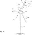
- Figure 1 shows a schematic, three-dimensional view of a wind turbine 100.
- the wind turbine 100 has a tower 102 and a nacelle 104 on the tower 102.
- An aerodynamic rotor 106 with three rotor blades 108 and a spinner 110 is provided on the nacelle 104.
- At least one of the rotor blades has a profile with at least one profile, which has a convex region on the suction side and one on the pressure side extending from the trailing edge (in Figure 1 not recognizable), such as in Figures 2 to 7 is shown.
- the aerodynamic rotor 106 is set into a rotary motion by the wind and thus also rotates an electrodynamic rotor or runner of a generator, which is directly or indirectly coupled to the aerodynamic rotor 106.
- the electrical generator is arranged in the nacelle 104 and generates electrical energy.
- the rotor blades 108 shown extend in particular in the longitudinal direction 112 with a profile course from a blade connection 114 to a blade tip 116.
- the profile course comprises in particular at least one profile (in Figure 1 not shown), as described below.
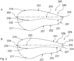
- the Figures 2A to 4B each show a profile 200 with a suction side 201 and a pressure side 202 opposite the suction side 201 in different design variants.
- the profile 200 preferably has a relative profile thickness, i.e. in particular a maximum thickness of the profile perpendicular to the profile chord 203 in relation to the profile chord length, of more than 25%.
- the profile chord length is defined here as the length of the profile chord 203, which extends from the front edge 204 to the rear edge 205.
- a convex region 206 extends on the suction side 201 as well as a convex region 207 on the pressure side.
- the pressure side 202 and/or the suction side 201 can in particular have further convex regions and/or concave regions.
- the pressure side 202 can, starting from the front edge 204, have a first convex region 217, a concave region 227 and a second convex region 207 adjacent to the concave region 227.
- Such a course of the pressure side 202 is shown, for example, in the Figures 2A to 3B
- the pressure side 202 and/or the suction side 201 can be designed to be convex overall.
- a profile 200 is shown with a closed trailing edge 205, in which the profile chord 203 preferably runs from the leading edge 204 to a point at which the profile converges, which is referred to as the trailing edge 205.
- Figure 2B shows a trailing edge with a pressure-side trailing edge 225 and a suction-side trailing edge 215 spaced apart from it. A midpoint between the suction-side trailing edge 215 and the pressure-side trailing edge 225 is used as the trailing edge 205 for determining the profile depth.
- the profiles 200 shown each have a skeleton line 230 which runs under the profile chord 203.
- the skeleton line 230 has a rear local minimum 231 in the region in which it is defined by the convex region 207 extending from the trailing edge 205 on the pressure side 202 and the convex region 206 extending from the trailing edge 205 on the suction side 201.
- the rear local minimum 231 lies under the profile chord 203.
- the skeleton line 230 has a front local minimum 232 in a region in which the skeleton line 230 is defined by a convex region 217 extending from the leading edge 204 on the pressure side 202 and the convex region 216 extending from the leading edge 204 on the suction side 201.
- the front local minimum 232 is also below the profile chord 203.
- the front local minimum 232 is the absolute minimum in the examples shown here.
- the pressure side 202 has a concave region 227 in a region between the convex region 207 and the convex region 217.
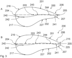
- a profile 200 is shown with a closed trailing edge 205, in which the profile chord 203 preferably runs from the leading edge 204 to a point at which the profile converges, which is referred to as the trailing edge 205.
- Figure 3B shows a trailing edge with a pressure-side trailing edge 225 and a suction-side trailing edge 215 spaced apart from it.
- the trailing edge 205 for determining the Profile depth is determined by a midpoint between the suction side trailing edge 215 and the pressure side trailing edge 225.
- the Figures 3A and 3B The profiles 200 shown each have a skeleton line 240 which runs under the profile chord 203.
- the skeleton line 240 has a rear local minimum 241 in the region in which it is defined by the convex region 207 extending from the trailing edge 205 on the pressure side 202 and the convex region 206 extending from the trailing edge 205 on the suction side 201.
- the rear local minimum 241 lies under the profile chord 203.
- the skeleton line 240 has a front local minimum 242 in a region in which the skeleton line 240 is defined by a convex region 217 extending from the leading edge 204 on the pressure side 202 and the convex region 216 extending from the leading edge 204 on the suction side 201.
- the front local minimum 242 is also below the profile chord 203.
- the pressure side 202 has a concave region 227 in a region between the convex region 216 and the convex region 217.
- the front local minimum 242 is the absolute minimum in the examples shown here.
- the skeleton line 240 runs at least partially over the profile chord 203.
- the skeleton line 240 intersects the profile chord 203 between the rear local minimum 241 and the front local minimum 242 at a first intersection point 243 and at a second intersection point 244.
- the skeleton line 240 runs between the first intersection point 243 and the second intersection point 244 over the profile chord 203.
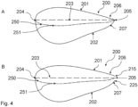
- a profile 200 is shown with a closed trailing edge 205, in which the profile chord 203 preferably runs from the leading edge 204 to a point at which the profile converges, which is referred to as the trailing edge 205.
- Figure 4B shows a trailing edge with a pressure-side trailing edge 225 and a suction-side trailing edge 215 spaced apart from it. A center point between the suction-side trailing edge 215 and the pressure-side trailing edge 225 is used as the trailing edge 205 for determining the profile depth.
- the Figures 4A and 4B The profiles shown each have a skeleton line 250 which runs under the profile chord 203 and has a mathematically positive curvature
- the positive curvature is defined by the substantially convex pressure side 202 and the substantially convex suction side 201.
- the skeleton line 250 has a single minimum 251 which lies below the profile chord 203.
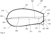
- a profile 300 with a suction side 301 and a pressure side 302 opposite the suction side 301 is shown.
- the profile 300 preferably has a relative profile thickness of more than 25%.
- the profile chord 303 extends from the leading edge 304 to the trailing edge 305.
- a convex region 306 extends on the suction side 301 and a convex region 307 extends on the pressure side.
- the convex region 307 defines a rounded transition region on which an arrangement 360 for aerodynamic flow control is arranged.
- a Gurney flap is shown schematically as an example of the arrangement 360.
- the profile 300 has a trailing edge with a pressure-side trailing edge 325 and a suction-side trailing edge 315 spaced apart therefrom. A midpoint between the suction-side trailing edge 315 and the pressure-side trailing edge 325 is used as the trailing edge 305 for determining the profile depth.
- the Figures 5 and 6 The profiles 300 shown each have a skeleton line 330 which runs partially under the profile chord 303.
- the skeleton line 330 has a minimum 331 in the area in which it is defined by the convex region 307 extending from the trailing edge 305 on the pressure side 302 and the convex region 306 extending from the trailing edge 305 on the suction side 301. The minimum 331 lies below the profile chord 303.
- the skeleton line 330 has a maximum 308 which lies above the profile chord 303 in a region in which the skeleton line 330 is defined by a convex region 317 extending on the pressure side 302 from the leading edge 304 and the convex region 316 extending on the suction side 301 from the leading edge 304.
- the arrangement 360 is in a first position in which the outer contour edge 361 of the arrangement 360 is spaced from the pressure-side trailing edge 325 and thus also from the suction-side trailing edge 315. This distance can in particular be at least 10% of the maximum profile thickness that occurs between the suction side 301 and the pressure side 302.
- the arrangement 360 is in a second position, which describes a lift-reduced configuration in which the distance between the outer contour edge 361 of the arrangement 360 and the pressure-side trailing edge 325 and thus also the suction-side trailing edge 315 is reduced.
- the arrangement 360 can be moved from the first position to the second position.
- the arrangement 360 can be designed to be actively controllable for buoyancy control.
- the Figures 5 and 6 show that the arrangement 360 is designed to adjust a height profile of the profile 300.
- the outer contour edge 361 can function as a pressure-side trailing edge.
- the height profile of the profile can correspond approximately to a height profile of a flatback profile 370 with a corresponding profile chord 371.
- a trailing edge defining this profile chord 371 coincides with the pressure-side trailing edge 325.
- This trailing edge is a midpoint between the outer contour edge 361 of the arrangement 360 and the suction-side trailing edge 315.
- a profile 300 is shown with a suction side 301 and a pressure side 302 opposite the suction side 301.
- the profile 300 preferably has a relative profile thickness of more than 25%.
- the profile chord 303 extends from the leading edge 304 to the closed trailing edge 305. Starting from the trailing edge 305, a convex region 306 extends on the suction side 301 and a convex region 307 extends on the pressure side.
- the profile has a skeleton line 330 which runs partially under the profile chord 303.
- the skeleton line 330 has a minimum 331 in the area in which it is defined by the convex region 307 extending from the trailing edge 305 on the pressure side 302 and the convex region 306 extending from the trailing edge 305 on the suction side 301.
- the minimum 331 lies below the profile chord 303.
- the skeleton line 330 has a maximum 308 which lies above the profile chord 303 in a region in which the skeleton line 330 is defined by a convex region 317 extending on the pressure side 302 from the leading edge 304 and the convex region 316 extending on the suction side 301 from the leading edge 304.
- the convex region 307 defines a rounded transition region on which an arrangement 380 for aerodynamic flow control is arranged.
- a Gurney flap is shown schematically as an example of the arrangement 380.
- the arrangement 380 can in particular be permanently installed or actively controllable in order to adapt a height profile of the profile 300 and to function as a pressure-side trailing edge.
- the arrangement 380 has a greater length.
- the length of an arrangement 360 can be greater the larger the radius of the rounding of the transition region.
- the height profile of the profile 300 can be optimally adjusted to approximately correspond to a height profile of a flatback profile 390 with a corresponding profile chord 391.
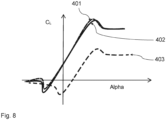
- FIG 8 A diagram is shown which shows the lift coefficients C L of different profiles as a function of the angle of attack ⁇ .
- Three graphs 401, 402, 403 can be seen, with graph 401 showing the lift coefficients of a profile with a rounded transition area on the pressure side to the trailing edge with an arrangement for aerodynamic flow control, graph 402 showing the lift coefficients of a flatback profile and graph 403 showing the lift coefficients of a profile with a rounded transition area on the pressure side to the trailing edge without an arrangement for aerodynamic flow control.
- Rotor blades with such profiles and wind turbines with these rotor blades have various advantages.
- the above-described embodiments allow lift coefficients to be adjusted as required.
- Another advantage is that the proposed solution can increase the overall efficiency of a wind turbine and, in particular, the annual yield.
- both the effort and costs of production can be reduced while saving weight.
Landscapes
- Engineering & Computer Science (AREA)
- Physics & Mathematics (AREA)
- Fluid Mechanics (AREA)
- Life Sciences & Earth Sciences (AREA)
- Sustainable Development (AREA)
- Sustainable Energy (AREA)
- Chemical & Material Sciences (AREA)
- Combustion & Propulsion (AREA)
- Mechanical Engineering (AREA)
- General Engineering & Computer Science (AREA)
- Wind Motors (AREA)
Claims (13)
- Pale de rotor (108) pour une éolienne (100), qui s'étend en direction longitudinale (112) avec un tracé de profil à partir d'un raccordement de pale (114) vers un bout de pale (116),dans laquelle le tracé de profil contient au moins un profil (200, 300), comprenant :- un côté d'aspiration (201, 301) et un côté de pression (202, 302),- une épaisseur de profil relative supérieure à 25 %,- une corde de profil (203, 303), qui s'étend entre un bord d'attaque (204, 304) et un bord arrière (205, 305) du profil (200, 300) et présente une longueur définissant la profondeur de profil,- une ligne moyenne (230, 240, 250, 330), qui passe au moins en partie au-dessous de la corde de profil (203, 303), par conséquent dans une couche dans une zone entre la corde de profil (203, 303) et le côté de pression (202, 302),- une zone convexe (206, 306) s'étendant sur le côté d'aspiration (201, 301) à partir du bord arrière (205, 305) et- une zone convexe (207, 307) s'étendant sur le côté de pression (202, 302) à partir du bord arrière (205, 305),dans laquelle la zone convexe (207, 307) sur le côté de pression (202, 302) définit une zone de transition arrondie du côté de pression (202, 302) vers le bord arrière (205, 305),caractérisée en ce quela ligne moyenne (230, 240, 250, 330), dans la zone dans laquelle la ligne moyenne (230, 240, 250, 330) est définie par la zone convexe (207, 307) s'étendant sur le côté de pression (202, 302) à partir du bord arrière (205, 305) et la zone convexe (206, 306) s'étendant sur le côté d'aspiration (201, 301) à partir du bord arrière (205, 305), présente un minimum local arrière (231, 241), qui se situe sous la corde de profil (203, 303), par conséquent dans une couche dans une zone entre la corde de profil (203, 303) et le côté de pression (202, 302), et que la ligne moyenne (230, 240, 250), dans une zone dans laquelle la ligne moyenne (230, 240, 250) est définie par une zone convexe (207) s'étendant sur le côté de pression (202) à partir du bord d'attaque (204) et la zone convexe (206) s'étendant sur le côté d'aspiration (201, 301) à partir du bord d'attaque (204, 304), présente un minimum local avant (232, 242, 251), qui se situe sous la corde de profil (203, 303), par conséquent dans une couche dans une zone entre la corde de profil (203, 303) et le côté de pression (202, 302), et/ou, en ce quetoute la ligne moyenne (230, 240, 250, 330) passe sous la corde de profil (203, 303), par conséquent dans une couche dans une zone entre la corde de profil (203, 303) et le côté de pression (202, 302).
- Pale de rotor (108) selon la revendication 1, dans laquelle un ensemble (360, 380) pour influer sur l'écoulement d'air aérodynamique est disposé sur la zone de transition arrondie,
dans laquelle de préférence l'ensemble (360, 380) est réalisé en tant que volet de Gurney ou volet d'intrados. - Pale de rotor (108) selon la revendication précédente 2, dans laquelle l'ensemble (360, 380) est disposé à un angle supérieur à 90° par rapport à une direction de soufflage théorique locale, en particulier supérieur à 100° par rapport à une direction de soufflage théorique locale, sur la zone de transition arrondie.
- Pale de rotor (108) selon au moins l'une des revendications précédentes 2 ou 3, dans laquelle l'ensemble (360, 380) présente une longueur comprise entre 0,1 % et 40 % de la profondeur de profil,
dans laquelle de préférence l'épaisseur de profil relative du profil (200, 300)- est au maximum de 30 % et la longueur de l'ensemble (360, 380) atteint au maximum 10 % de la profondeur de profil ou- est supérieure à 30 % et la longueur de l'ensemble (360, 380) atteint au maximum 40 % de la profondeur de profil. - Pale de rotor (108) selon la revendication précédente 4, dans laquelle l'ensemble (360, 380) est mobile à partir d'une première position, dans laquelle l'écart entre le bord de contour extérieur (361) de l'ensemble (360, 380) et le bord de fuite côté aspiration atteint au moins 10 % de l'épaisseur de profil maximale apparaissant entre le côté d'aspiration (201, 301) et le côté de pression (202, 302), en direction d'une deuxième position, qui décrit une configuration à portance réduite dans laquelle l'écart entre le bord de contour extérieur (361) de l'ensemble (360, 380) et le bord de fuite côté aspiration (315) est réduit.
- Pale de rotor (108) selon au moins l'une des revendications précédentes 2 à 5, dans laquelle l'ensemble (360, 380) est réalisé de manière à pouvoir être commandé activement pour le contrôle de portance.
- Pale de rotor (108) selon au moins l'une des revendications précédentes, dans laquelle la ligne moyenne (230, 240, 250, 330), dans une zone dans laquelle la ligne moyenne (230, 240, 250, 330) est définie par la zone convexe (207, 307) s'étendant sur le côté de pression (202, 302) à partir du bord arrière (205, 305) et la zone convexe (206, 306) s'étendant sur le côté d'aspiration (201, 301) à partir du bord arrière (205, 305), passe sous la corde de profil (203, 303) et/ou présente une courbure mathématiquement positive.
- Pale de rotor (108) selon au moins l'une des revendications précédentes, comprenant le minimum local avant (232, 242) et le minimum local arrière (231, 241),dans laquelle le côté de pression (202, 302), dans une zone qui entre la zone convexe (217), qui s'étend à partir du bord d'attaque (204, 304), et la zone convexe (207), qui s'étend à partir du bord arrière (205, 305), présente une zone concave (227),dans laquelle de préférence le minimum local arrière (231, 241) ou le minimum local avant (232, 242) est un minimum absolu.
- Pale de rotor (108) selon au moins l'une des revendications précédentes, dans laquelle le bord arrière (205, 305)- est un bord arrière (205, 305) fermé ou- est un bord arrière (205, 305) plat, dans laquelle une hauteur du bord arrière (205, 305) plat∘ est inférieure à 40 %, de préférence inférieure à 20 %, de préférence inférieure à 10 %, de l'épaisseur de profil maximale apparaissant entre le côté d'aspiration (201, 301) et le côté de pression (202, 302), et/ou∘ éventuellement atteint à peu près 50 % de l'écart entre le bord de contour extérieur de l'ensemble (360, 380) et le bord de fuite côté aspiration.
- Pale de rotor (108) selon au moins l'une des revendications précédentes, dans laquelle le profil (200, 300) présente une réserve d'épaisseur, qui définit un rapport d'un écart d'une épaisseur de profil maximale par rapport au bord d'attaque (204, 304) en direction de la corde de profil (203, 303) et de la longueur de la corde de profil (203, 303), dans laquelle le rapport est de préférence inférieur à 40 %.
- Eolienne (100) avec au moins une pale de rotor (108) selon au moins l'une des revendications précédentes 1 à 10.
- Procédé pour la conception d'une pale de rotor (108), qui s'étend en direction longitudinale (112) avec un tracé de profil à partir d'un raccordement de pale (114) vers un bout de pale (116), avec les étapes :- de sélection d'au moins un profil (200, 300) pour le tracé de profil, comprenant∘ un côté d'aspiration (201, 301) et un côté de pression (202, 302),∘ une épaisseur de profil relative supérieure à 25 %,∘ une corde de profil (203, 303), qui s'étend entre un bord d'attaque (204, 304) et un bord arrière (205, 305) du profil (200, 300) et présente une longueur définissant une profondeur de profil,∘ une ligne moyenne (230, 240, 250, 330), qui passe au moins en partie sous la corde de profil (203, 303), par conséquent dans une couche dans une zone entre la corde de profil (203, 303) et le côté de pression (202, 302),∘ une zone convexe s'étendant sur le côté d'aspiration (201, 301) à partir du bord arrière (205, 305) et∘ une zone convexe s'étendant sur le côté de pression (202, 302) à partir du bord arrière (205, 305),dans lequel la zone convexe sur le côté de pression (202, 302) définit une zone de transition arrondie du côté de pression (202, 302) vers le bord arrière (205, 305),- de préférence d'adaptation d'un tracé de hauteur d'un profil (200, 300) par disposition d'un ensemble (360, 380) pour influencer l'écoulement aérodynamique sur la zone de transition arrondie,dans lequel la sélection de l'au moins un profil (200, 300) et/ou l'adaptation du tracé de hauteur repose au moins en partie sur un calcul d'un rendement énergétique annuel à obtenir et/ou une détermination de cas de charge spécifiques au site attendus, caractérisé en ce quela ligne moyenne (230, 240, 250, 330), dans la zone dans laquelle la ligne moyenne (230, 240, 250, 330) est définie par la zone convexe (207, 307) s'étendant sur le côté de pression (202, 302) à partir du bord arrière (205, 305) et la zone convexe (206, 306) s'étendant sur le côté d'aspiration (201, 301) à partir du bord arrière (205, 305), présente un minimum local arrière (231, 241), qui se situe sous la corde de profil (203, 303), par conséquent dans une couche dans une zone entre la corde de profil (203, 303) et le côté de pression (202, 302), et quela ligne moyenne (230, 240, 250), dans une zone dans laquelle la ligne moyenne (230, 240, 250) est définie par une zone convexe (207) s'étendant sur le côté de pression (202) à partir du bord d'attaque (204) et la zone convexe (206) s'étendant sur le côté d'aspiration (201, 301) à partir du bord d'attaque (204, 304), présente un minimum local avant (232, 242, 251), qui se situe sous la corde de profil (203, 303), par conséquent dans une couche dans une zone entre la corde de profil (203, 303) et le côté de pression (202, 302), et/ou quetoute la ligne moyenne (230, 240, 250, 330) passe sous la corde de profil (203, 303), par conséquent dans une couche dans une zone entre la corde de profil (203, 303) et le côté de pression (202, 302).
- Procédé selon la revendication précédente 12, dans lequel le tracé de hauteur du profil (200, 300) est adapté de telle sorte qu'un écart entre un bord de contour extérieur de l'ensemble (360, 380) et un bord de fuite côté aspiration atteint au moins 10 % d'une épaisseur de profil maximale apparaissant entre le côté d'aspiration (201, 301) et le côté de pression (202, 302),
de préférence comprenant en outre l'étape :- d'adaptation d'un coefficient de portance local, en particulier à un état de fonctionnement d'une éolienne (100), par une orientation de l'ensemble (360, 380) par∘ déplacement de l'ensemble (360, 380) à partir d'une première position, dans laquelle l'écart entre un bord de contour extérieur de l'ensemble (360, 380) et un bord de fuite côté aspiration atteint au moins 10 % de l'épaisseur de profil maximale apparaissant entre le côté d'aspiration (201, 301) et le côté de pression (202, 302), en direction d'une deuxième position, qui décrit une configuration à portance réduite dans laquelle l'écart entre le bord de contour extérieur de l'ensemble (360, 380) et le bord de fuite côté aspiration est réduit et/ou∘ déplacement de l'ensemble (360, 380) à partir d'une deuxième position, qui décrit une configuration à portance réduite dans laquelle l'écart entre le bord de contour extérieur de l'ensemble (360, 380) et le bord de fuite côté aspiration est inférieur à 10 % de l'épaisseur de profil maximale apparaissant entre le côté d'aspiration (201, 301) et le côté de pression (202, 302), en direction d'une première position dans laquelle l'écart entre un bord de contour extérieur de l'ensemble (360, 380) et un bord de fuite côté aspiration atteint au moins 10 % de l'épaisseur de profil maximale apparaissant entre le côté d'aspiration (201, 301) et le côté de pression (202, 302).
Applications Claiming Priority (1)
| Application Number | Priority Date | Filing Date | Title |
|---|---|---|---|
| DE102020126484 | 2020-10-09 |
Publications (3)
| Publication Number | Publication Date |
|---|---|
| EP3981981A1 EP3981981A1 (fr) | 2022-04-13 |
| EP3981981B1 true EP3981981B1 (fr) | 2024-12-25 |
| EP3981981C0 EP3981981C0 (fr) | 2024-12-25 |
Family
ID=78085490
Family Applications (1)
| Application Number | Title | Priority Date | Filing Date |
|---|---|---|---|
| EP21201104.3A Active EP3981981B1 (fr) | 2020-10-09 | 2021-10-06 | Pale de rotor pour une éolienne, éolienne et procédé de conception d'une pale de rotor |
Country Status (3)
| Country | Link |
|---|---|
| US (1) | US11867145B2 (fr) |
| EP (1) | EP3981981B1 (fr) |
| CN (1) | CN114320733A (fr) |
Families Citing this family (2)
| Publication number | Priority date | Publication date | Assignee | Title |
|---|---|---|---|---|
| DE102018103678A1 (de) * | 2018-02-19 | 2019-08-22 | Wobben Properties Gmbh | Rotorblatt einer Windenergieanlage mit einer Splitterplatte |
| EP4491868A1 (fr) | 2023-07-10 | 2025-01-15 | Wobben Properties GmbH | Pale de rotor d'éolienne et procédé de fabrication d'une pale de rotor d'éolienne |
Family Cites Families (16)
| Publication number | Priority date | Publication date | Assignee | Title |
|---|---|---|---|---|
| EP1845258A1 (fr) | 2006-04-10 | 2007-10-17 | Siemens Aktiengesellschaft | Pale de rotor d'éolienne |
| EP1944505B1 (fr) | 2007-01-12 | 2012-11-28 | Siemens Aktiengesellschaft | Aube de rotor d'éolienne avec générateurs de tourbillons |
| US7828523B2 (en) | 2007-03-27 | 2010-11-09 | General Electric Company | Rotor blade for a wind turbine having a variable dimension |
| ES2320962B1 (es) | 2007-11-28 | 2010-03-11 | GAMESA INNOVATION & TECHNOLOGY S.L. | Perfil aerodinamico para la raiz de una pala de aerogenerador con doble borde de ataque. |
| DE102008052858B9 (de) * | 2008-10-23 | 2014-06-12 | Senvion Se | Profil eines Rotorblatts und Rotorblatt einer Windenergieanlage |
| EP2141358A1 (fr) | 2008-12-12 | 2010-01-06 | Lm Glasfiber A/S | Pale d'éolienne dotée d'un déflecteur avec une séparation efficace de la circulation de l'air |
| DE102013202666A1 (de) * | 2013-02-19 | 2014-08-21 | Senvion Se | Rotorblatt einer Windenergieanlage |
| DK3027892T3 (en) * | 2013-08-02 | 2017-07-24 | Vestas Wind Sys As | Blade for a wind turbine and a method for making a blade for a wind turbine |
| GB2526847A (en) * | 2014-06-05 | 2015-12-09 | Vestas Wind Sys As | Wind turbine blade with trailing edge flap |
| US20160298600A1 (en) * | 2015-04-08 | 2016-10-13 | Frontier Wind, Llc | Load Compensating Devices |
| US10495056B2 (en) | 2015-09-03 | 2019-12-03 | Siemens Gamesa Renewable Energy A/S | Wind turbine blade with trailing edge tab |
| DE202016101461U1 (de) | 2016-03-16 | 2016-03-31 | Institute of Aerospace Technology (IAT) der Hochschule Bremen | Rotorblatt für Windenergieanlagen mit horizontaler Drehachse sowieWindenergieanlage mit selbigem |
| CN106050566B (zh) * | 2016-07-13 | 2018-11-16 | 西北工业大学 | 一种钝后缘风力机翼型环量控制装置及方法 |
| WO2018103803A1 (fr) * | 2016-12-06 | 2018-06-14 | Vestas Wind Systems A/S | Pale d'éolienne ayant un bord de fuite tronqué |
| DE102018103678A1 (de) * | 2018-02-19 | 2019-08-22 | Wobben Properties Gmbh | Rotorblatt einer Windenergieanlage mit einer Splitterplatte |
| DE102019113085A1 (de) | 2019-05-17 | 2020-11-19 | Wobben Properties Gmbh | Rotorblatt und Windenergieanlage |
-
2021
- 2021-10-06 EP EP21201104.3A patent/EP3981981B1/fr active Active
- 2021-10-08 US US17/497,220 patent/US11867145B2/en active Active
- 2021-10-09 CN CN202111176158.0A patent/CN114320733A/zh not_active Withdrawn
Also Published As
| Publication number | Publication date |
|---|---|
| US20220112874A1 (en) | 2022-04-14 |
| EP3981981C0 (fr) | 2024-12-25 |
| CN114320733A (zh) | 2022-04-12 |
| EP3981981A1 (fr) | 2022-04-13 |
| US11867145B2 (en) | 2024-01-09 |
Similar Documents
| Publication | Publication Date | Title |
|---|---|---|
| EP1514023B1 (fr) | Eolienne | |
| DE102011051831B4 (de) | Rotorblatt für eine Windkraftanlage mit einem Saugseitenwinglet | |
| EP1620646B1 (fr) | Pale de rotor d'une installation a energie eolienne | |
| DE102011055370B4 (de) | Winglet für einen Rotorflügel einer Windkraftanlage | |
| DE102011051985B4 (de) | Rotorblattvorrichtung | |
| DE102011053712B4 (de) | Windturbinenrotorblatt mit betätigbaren profilpassagen | |
| EP3755899B1 (fr) | Pale de rotor d'une installation éolienne comprenant une plaque de déviation de la couche limite | |
| EP2280163B1 (fr) | Eolienne et pale de rotor d'une eolienne | |
| DE102012109171B4 (de) | Windkraftanlagenrotorblatt mit passiv modifizierter Abströmkantenkomponente | |
| EP2998572B1 (fr) | Pale de rotor d'éoliennes | |
| EP1524431B1 (fr) | Pale pour éolienne avec volets de bord de fuite | |
| DE102012100593A1 (de) | Steuerbare Oberflächenmerkmale für Rotorblätter von Windkraftanlagen | |
| EP3981981B1 (fr) | Pale de rotor pour une éolienne, éolienne et procédé de conception d'une pale de rotor | |
| DE102017117843A1 (de) | Rotorblatt eines Rotors einer Windenergieanlage, Windenergieanlage und Verfahren zur Verbesserung des Wirkungsgrades eines Rotors einer Windenergieanlage | |
| WO2016009032A1 (fr) | Pale de rotor d'éolienne, bord de fuite de pointe de pale de rotor d'éolienne, procédé de fabrication d'une pale de rotor d'éolienne et éolienne | |
| EP3737856B1 (fr) | Éolienne comprenant un volet d'écoulement de bord de fuite | |
| EP2885533B1 (fr) | Installation génératrice d'énergie à flux | |
| EP2366892A1 (fr) | Pale de rotor d'éolienne | |
| EP3824176B1 (fr) | Pale de rotor pour éolienne et éolienne | |
| WO2020234190A1 (fr) | Pale de rotor et éolienne | |
| EP4230862B1 (fr) | Pale de rotor d'une éolienne | |
| EP3963204B1 (fr) | Rotor pour une éolienne et éolienne | |
| EP3969741B1 (fr) | Pale de rotor et éolienne | |
| EP3954892A2 (fr) | Pale de rotor pour une éolienne, rotor pour une éolienne, construction et éolienne | |
| EP3280910A1 (fr) | Pale de rotor d'éolienne |
Legal Events
| Date | Code | Title | Description |
|---|---|---|---|
| PUAI | Public reference made under article 153(3) epc to a published international application that has entered the european phase |
Free format text: ORIGINAL CODE: 0009012 |
|
| STAA | Information on the status of an ep patent application or granted ep patent |
Free format text: STATUS: THE APPLICATION HAS BEEN PUBLISHED |
|
| AK | Designated contracting states |
Kind code of ref document: A1 Designated state(s): AL AT BE BG CH CY CZ DE DK EE ES FI FR GB GR HR HU IE IS IT LI LT LU LV MC MK MT NL NO PL PT RO RS SE SI SK SM TR |
|
| STAA | Information on the status of an ep patent application or granted ep patent |
Free format text: STATUS: REQUEST FOR EXAMINATION WAS MADE |
|
| 17P | Request for examination filed |
Effective date: 20221013 |
|
| RBV | Designated contracting states (corrected) |
Designated state(s): AL AT BE BG CH CY CZ DE DK EE ES FI FR GB GR HR HU IE IS IT LI LT LU LV MC MK MT NL NO PL PT RO RS SE SI SK SM TR |
|
| GRAP | Despatch of communication of intention to grant a patent |
Free format text: ORIGINAL CODE: EPIDOSNIGR1 |
|
| STAA | Information on the status of an ep patent application or granted ep patent |
Free format text: STATUS: GRANT OF PATENT IS INTENDED |
|
| INTG | Intention to grant announced |
Effective date: 20240808 |
|
| GRAS | Grant fee paid |
Free format text: ORIGINAL CODE: EPIDOSNIGR3 |
|
| GRAA | (expected) grant |
Free format text: ORIGINAL CODE: 0009210 |
|
| STAA | Information on the status of an ep patent application or granted ep patent |
Free format text: STATUS: THE PATENT HAS BEEN GRANTED |
|
| AK | Designated contracting states |
Kind code of ref document: B1 Designated state(s): AL AT BE BG CH CY CZ DE DK EE ES FI FR GB GR HR HU IE IS IT LI LT LU LV MC MK MT NL NO PL PT RO RS SE SI SK SM TR |
|
| REG | Reference to a national code |
Ref country code: GB Ref legal event code: FG4D Free format text: NOT ENGLISH |
|
| RIN1 | Information on inventor provided before grant (corrected) |
Inventor name: KNOBBE ESCHEN, HENRY Inventor name: MAASS, HAUKE Inventor name: STEMBERG, JOCHEN |
|
| REG | Reference to a national code |
Ref country code: CH Ref legal event code: EP |
|
| REG | Reference to a national code |
Ref country code: DE Ref legal event code: R096 Ref document number: 502021006195 Country of ref document: DE |
|
| REG | Reference to a national code |
Ref country code: IE Ref legal event code: FG4D Free format text: LANGUAGE OF EP DOCUMENT: GERMAN |
|
| U01 | Request for unitary effect filed |
Effective date: 20250115 |
|
| U07 | Unitary effect registered |
Designated state(s): AT BE BG DE DK EE FI FR IT LT LU LV MT NL PT RO SE SI Effective date: 20250121 |
|
| PG25 | Lapsed in a contracting state [announced via postgrant information from national office to epo] |
Ref country code: HR Free format text: LAPSE BECAUSE OF FAILURE TO SUBMIT A TRANSLATION OF THE DESCRIPTION OR TO PAY THE FEE WITHIN THE PRESCRIBED TIME-LIMIT Effective date: 20241225 |
|
| PG25 | Lapsed in a contracting state [announced via postgrant information from national office to epo] |
Ref country code: NO Free format text: LAPSE BECAUSE OF FAILURE TO SUBMIT A TRANSLATION OF THE DESCRIPTION OR TO PAY THE FEE WITHIN THE PRESCRIBED TIME-LIMIT Effective date: 20250325 |
|
| PG25 | Lapsed in a contracting state [announced via postgrant information from national office to epo] |
Ref country code: GR Free format text: LAPSE BECAUSE OF FAILURE TO SUBMIT A TRANSLATION OF THE DESCRIPTION OR TO PAY THE FEE WITHIN THE PRESCRIBED TIME-LIMIT Effective date: 20250326 |
|
| PG25 | Lapsed in a contracting state [announced via postgrant information from national office to epo] |
Ref country code: RS Free format text: LAPSE BECAUSE OF FAILURE TO SUBMIT A TRANSLATION OF THE DESCRIPTION OR TO PAY THE FEE WITHIN THE PRESCRIBED TIME-LIMIT Effective date: 20250325 |
|
| PG25 | Lapsed in a contracting state [announced via postgrant information from national office to epo] |
Ref country code: SM Free format text: LAPSE BECAUSE OF FAILURE TO SUBMIT A TRANSLATION OF THE DESCRIPTION OR TO PAY THE FEE WITHIN THE PRESCRIBED TIME-LIMIT Effective date: 20241225 |
|
| PG25 | Lapsed in a contracting state [announced via postgrant information from national office to epo] |
Ref country code: PL Free format text: LAPSE BECAUSE OF FAILURE TO SUBMIT A TRANSLATION OF THE DESCRIPTION OR TO PAY THE FEE WITHIN THE PRESCRIBED TIME-LIMIT Effective date: 20241225 |
|
| PG25 | Lapsed in a contracting state [announced via postgrant information from national office to epo] |
Ref country code: ES Free format text: LAPSE BECAUSE OF FAILURE TO SUBMIT A TRANSLATION OF THE DESCRIPTION OR TO PAY THE FEE WITHIN THE PRESCRIBED TIME-LIMIT Effective date: 20241225 |
|
| PG25 | Lapsed in a contracting state [announced via postgrant information from national office to epo] |
Ref country code: IS Free format text: LAPSE BECAUSE OF FAILURE TO SUBMIT A TRANSLATION OF THE DESCRIPTION OR TO PAY THE FEE WITHIN THE PRESCRIBED TIME-LIMIT Effective date: 20250425 |
|
| PG25 | Lapsed in a contracting state [announced via postgrant information from national office to epo] |
Ref country code: SK Free format text: LAPSE BECAUSE OF FAILURE TO SUBMIT A TRANSLATION OF THE DESCRIPTION OR TO PAY THE FEE WITHIN THE PRESCRIBED TIME-LIMIT Effective date: 20241225 |
|
| PG25 | Lapsed in a contracting state [announced via postgrant information from national office to epo] |
Ref country code: CZ Free format text: LAPSE BECAUSE OF FAILURE TO SUBMIT A TRANSLATION OF THE DESCRIPTION OR TO PAY THE FEE WITHIN THE PRESCRIBED TIME-LIMIT Effective date: 20241225 |
|
| PLBE | No opposition filed within time limit |
Free format text: ORIGINAL CODE: 0009261 |
|
| STAA | Information on the status of an ep patent application or granted ep patent |
Free format text: STATUS: NO OPPOSITION FILED WITHIN TIME LIMIT |
|
| U20 | Renewal fee for the european patent with unitary effect paid |
Year of fee payment: 5 Effective date: 20250930 |
|
| 26N | No opposition filed |
Effective date: 20250926 |