EP3954892A2 - Rotor blade for a wind turbine, rotor for a wind turbine, structure and wind turbine - Google Patents
Rotor blade for a wind turbine, rotor for a wind turbine, structure and wind turbine Download PDFInfo
- Publication number
- EP3954892A2 EP3954892A2 EP21185491.4A EP21185491A EP3954892A2 EP 3954892 A2 EP3954892 A2 EP 3954892A2 EP 21185491 A EP21185491 A EP 21185491A EP 3954892 A2 EP3954892 A2 EP 3954892A2
- Authority
- EP
- European Patent Office
- Prior art keywords
- rotor blade
- trailing edge
- suction
- pressure
- area
- Prior art date
- Legal status (The legal status is an assumption and is not a legal conclusion. Google has not performed a legal analysis and makes no representation as to the accuracy of the status listed.)
- Pending
Links
- 230000007704 transition Effects 0.000 claims description 31
- 230000003068 static effect Effects 0.000 claims description 4
- 230000007423 decrease Effects 0.000 claims description 2
- 229910000870 Weathering steel Inorganic materials 0.000 claims 1
- 230000003247 decreasing effect Effects 0.000 claims 1
- XUKUURHRXDUEBC-KAYWLYCHSA-N Atorvastatin Chemical compound C=1C=CC=CC=1C1=C(C=2C=CC(F)=CC=2)N(CC[C@@H](O)C[C@@H](O)CC(O)=O)C(C(C)C)=C1C(=O)NC1=CC=CC=C1 XUKUURHRXDUEBC-KAYWLYCHSA-N 0.000 abstract 1
- 108090000623 proteins and genes Proteins 0.000 abstract 1
- 238000009434 installation Methods 0.000 description 9
- 230000009467 reduction Effects 0.000 description 9
- XLYOFNOQVPJJNP-UHFFFAOYSA-N water Substances O XLYOFNOQVPJJNP-UHFFFAOYSA-N 0.000 description 9
- 230000008901 benefit Effects 0.000 description 7
- 238000011161 development Methods 0.000 description 6
- 230000018109 developmental process Effects 0.000 description 6
- 230000015572 biosynthetic process Effects 0.000 description 5
- 238000000926 separation method Methods 0.000 description 5
- 238000004519 manufacturing process Methods 0.000 description 3
- 230000004048 modification Effects 0.000 description 3
- 238000012986 modification Methods 0.000 description 3
- 230000001419 dependent effect Effects 0.000 description 2
- 230000000737 periodic effect Effects 0.000 description 2
- 206010041662 Splinter Diseases 0.000 description 1
- 230000000694 effects Effects 0.000 description 1
- 230000005520 electrodynamics Effects 0.000 description 1
- 238000007373 indentation Methods 0.000 description 1
- 230000001788 irregular Effects 0.000 description 1
- 230000007935 neutral effect Effects 0.000 description 1
- 230000010355 oscillation Effects 0.000 description 1
- 230000003746 surface roughness Effects 0.000 description 1
Images


Classifications
-
- F—MECHANICAL ENGINEERING; LIGHTING; HEATING; WEAPONS; BLASTING
- F03—MACHINES OR ENGINES FOR LIQUIDS; WIND, SPRING, OR WEIGHT MOTORS; PRODUCING MECHANICAL POWER OR A REACTIVE PROPULSIVE THRUST, NOT OTHERWISE PROVIDED FOR
- F03D—WIND MOTORS
- F03D1/00—Wind motors with rotation axis substantially parallel to the air flow entering the rotor
- F03D1/06—Rotors
- F03D1/0608—Rotors characterised by their aerodynamic shape
- F03D1/0633—Rotors characterised by their aerodynamic shape of the blades
-
- F—MECHANICAL ENGINEERING; LIGHTING; HEATING; WEAPONS; BLASTING
- F03—MACHINES OR ENGINES FOR LIQUIDS; WIND, SPRING, OR WEIGHT MOTORS; PRODUCING MECHANICAL POWER OR A REACTIVE PROPULSIVE THRUST, NOT OTHERWISE PROVIDED FOR
- F03D—WIND MOTORS
- F03D1/00—Wind motors with rotation axis substantially parallel to the air flow entering the rotor
- F03D1/06—Rotors
- F03D1/065—Rotors characterised by their construction elements
- F03D1/0675—Rotors characterised by their construction elements of the blades
-
- F—MECHANICAL ENGINEERING; LIGHTING; HEATING; WEAPONS; BLASTING
- F03—MACHINES OR ENGINES FOR LIQUIDS; WIND, SPRING, OR WEIGHT MOTORS; PRODUCING MECHANICAL POWER OR A REACTIVE PROPULSIVE THRUST, NOT OTHERWISE PROVIDED FOR
- F03D—WIND MOTORS
- F03D13/00—Assembly, mounting or commissioning of wind motors; Arrangements specially adapted for transporting wind motor components
- F03D13/20—Arrangements for mounting or supporting wind motors; Masts or towers for wind motors
-
- F—MECHANICAL ENGINEERING; LIGHTING; HEATING; WEAPONS; BLASTING
- F03—MACHINES OR ENGINES FOR LIQUIDS; WIND, SPRING, OR WEIGHT MOTORS; PRODUCING MECHANICAL POWER OR A REACTIVE PROPULSIVE THRUST, NOT OTHERWISE PROVIDED FOR
- F03D—WIND MOTORS
- F03D80/00—Details, components or accessories not provided for in groups F03D1/00 - F03D17/00
-
- F—MECHANICAL ENGINEERING; LIGHTING; HEATING; WEAPONS; BLASTING
- F03—MACHINES OR ENGINES FOR LIQUIDS; WIND, SPRING, OR WEIGHT MOTORS; PRODUCING MECHANICAL POWER OR A REACTIVE PROPULSIVE THRUST, NOT OTHERWISE PROVIDED FOR
- F03D—WIND MOTORS
- F03D7/00—Controlling wind motors
- F03D7/02—Controlling wind motors the wind motors having rotation axis substantially parallel to the air flow entering the rotor
- F03D7/022—Adjusting aerodynamic properties of the blades
-
- F—MECHANICAL ENGINEERING; LIGHTING; HEATING; WEAPONS; BLASTING
- F05—INDEXING SCHEMES RELATING TO ENGINES OR PUMPS IN VARIOUS SUBCLASSES OF CLASSES F01-F04
- F05B—INDEXING SCHEME RELATING TO WIND, SPRING, WEIGHT, INERTIA OR LIKE MOTORS, TO MACHINES OR ENGINES FOR LIQUIDS COVERED BY SUBCLASSES F03B, F03D AND F03G
- F05B2240/00—Components
- F05B2240/10—Stators
- F05B2240/13—Stators to collect or cause flow towards or away from turbines
- F05B2240/132—Stators to collect or cause flow towards or away from turbines creating a vortex or tornado effect
-
- F—MECHANICAL ENGINEERING; LIGHTING; HEATING; WEAPONS; BLASTING
- F05—INDEXING SCHEMES RELATING TO ENGINES OR PUMPS IN VARIOUS SUBCLASSES OF CLASSES F01-F04
- F05B—INDEXING SCHEME RELATING TO WIND, SPRING, WEIGHT, INERTIA OR LIKE MOTORS, TO MACHINES OR ENGINES FOR LIQUIDS COVERED BY SUBCLASSES F03B, F03D AND F03G
- F05B2240/00—Components
- F05B2240/20—Rotors
- F05B2240/21—Rotors for wind turbines
- F05B2240/211—Rotors for wind turbines with vertical axis
-
- F—MECHANICAL ENGINEERING; LIGHTING; HEATING; WEAPONS; BLASTING
- F05—INDEXING SCHEMES RELATING TO ENGINES OR PUMPS IN VARIOUS SUBCLASSES OF CLASSES F01-F04
- F05B—INDEXING SCHEME RELATING TO WIND, SPRING, WEIGHT, INERTIA OR LIKE MOTORS, TO MACHINES OR ENGINES FOR LIQUIDS COVERED BY SUBCLASSES F03B, F03D AND F03G
- F05B2240/00—Components
- F05B2240/20—Rotors
- F05B2240/30—Characteristics of rotor blades, i.e. of any element transforming dynamic fluid energy to or from rotational energy and being attached to a rotor
- F05B2240/304—Details of the trailing edge
-
- Y—GENERAL TAGGING OF NEW TECHNOLOGICAL DEVELOPMENTS; GENERAL TAGGING OF CROSS-SECTIONAL TECHNOLOGIES SPANNING OVER SEVERAL SECTIONS OF THE IPC; TECHNICAL SUBJECTS COVERED BY FORMER USPC CROSS-REFERENCE ART COLLECTIONS [XRACs] AND DIGESTS
- Y02—TECHNOLOGIES OR APPLICATIONS FOR MITIGATION OR ADAPTATION AGAINST CLIMATE CHANGE
- Y02B—CLIMATE CHANGE MITIGATION TECHNOLOGIES RELATED TO BUILDINGS, e.g. HOUSING, HOUSE APPLIANCES OR RELATED END-USER APPLICATIONS
- Y02B10/00—Integration of renewable energy sources in buildings
- Y02B10/30—Wind power
-
- Y—GENERAL TAGGING OF NEW TECHNOLOGICAL DEVELOPMENTS; GENERAL TAGGING OF CROSS-SECTIONAL TECHNOLOGIES SPANNING OVER SEVERAL SECTIONS OF THE IPC; TECHNICAL SUBJECTS COVERED BY FORMER USPC CROSS-REFERENCE ART COLLECTIONS [XRACs] AND DIGESTS
- Y02—TECHNOLOGIES OR APPLICATIONS FOR MITIGATION OR ADAPTATION AGAINST CLIMATE CHANGE
- Y02E—REDUCTION OF GREENHOUSE GAS [GHG] EMISSIONS, RELATED TO ENERGY GENERATION, TRANSMISSION OR DISTRIBUTION
- Y02E10/00—Energy generation through renewable energy sources
- Y02E10/70—Wind energy
- Y02E10/72—Wind turbines with rotation axis in wind direction
-
- Y—GENERAL TAGGING OF NEW TECHNOLOGICAL DEVELOPMENTS; GENERAL TAGGING OF CROSS-SECTIONAL TECHNOLOGIES SPANNING OVER SEVERAL SECTIONS OF THE IPC; TECHNICAL SUBJECTS COVERED BY FORMER USPC CROSS-REFERENCE ART COLLECTIONS [XRACs] AND DIGESTS
- Y02—TECHNOLOGIES OR APPLICATIONS FOR MITIGATION OR ADAPTATION AGAINST CLIMATE CHANGE
- Y02E—REDUCTION OF GREENHOUSE GAS [GHG] EMISSIONS, RELATED TO ENERGY GENERATION, TRANSMISSION OR DISTRIBUTION
- Y02E10/00—Energy generation through renewable energy sources
- Y02E10/70—Wind energy
- Y02E10/728—Onshore wind turbines
Definitions
- the invention relates to a rotor blade for a wind power plant, a rotor for a wind power plant, a structure and a wind power plant with a rotor and/or a structure.
- Wind energy installations have a rotor with at least one, two or more rotor blades, preferably three rotor blades, and are designed to generate mechanical rotational energy from kinetic wind energy and electrical energy from this.
- Such wind energy installations are generally known and generally comprise a nacelle on which the rotor is arranged and a tower on which the nacelle with the rotor is arranged so as to be rotatable about an essentially vertically aligned axis.
- Wind turbines are generally designed as so-called horizontal-axis wind turbines, which include a rotor with an essentially horizontal axis, the rotor blades of which rotate in a plane essentially perpendicular to the wind.
- Such horizontal-axis wind turbines use the aerodynamic principle of lift to convert the kinetic wind energy into mechanical rotational energy.
- a profile of a rotor blade forms a suction side and a pressure side, so that when moving air flows around the profile, a negative pressure is created on the suction side compared to the pressure side.
- the resulting pressure difference between the pressure side and the suction side leads to an aerodynamic lift.
- the lift is dependent, for example, on an angle of attack of the rotor blades.
- Known rotor blades are disadvantageous in that the adjacent air flow, in particular on a suction side, breaks off and a so-called forms a "dead water area" with a separated flow. Especially with larger angles of attack, the flow can no longer rest smoothly against a profile of a rotor blade and breaks off.
- the dead water area reduces the lift of the rotor blade and decelerates the rotor blade by increasing its drag. This reduces the efficiency of the rotor and thus also the yield of a wind energy installation.
- Vortex generators in an area between 10% and 60% of the chord length of the profile, starting from a leading edge of the profile.
- the vortex generators serve to generate local regions of turbulent air currents over a surface of the rotor blade in order to increase the resistance to flow separation.
- vortex generators swirl a flow close to the wall on the rotor blade, as a result of which the momentum exchange between the flow layers close to the wall and those farther away from the wall increases significantly and the flow velocities in the boundary layer close to the wall increase.
- resistance is generated by the vortex generators themselves, so that the yield of the wind turbine cannot be increased or can only be increased slightly.
- Another disadvantage of this arrangement of the vortex generators is that they produce loud noises.
- rotor blades with an at least partially blunt trailing edge in the interior.
- Such rotor blades are particularly disadvantageous in that in the area of the blunt trailing edge, the lift performance is reduced due to the lower blade depth and vortices can also form in this area in the form of a so-called Karman vortex street, which results in increased air resistance and increased noise emissions.
- Wind turbines can also be subject to site-dependent framework conditions, such as with regard to a noise level that should not be exceeded.
- the wind turbines are often operated in a noise-reduced operating mode with a reduced nominal rotor speed compared to the power-optimized operating mode.
- German Patent and Trademark Office has researched the following prior art in the priority application for the present application: WO 2016/ 055 076 A1 , GB 2 526 847 A , EP 3 480 457 A1 , EP 3 029 313 A1 , DE 10 2018 103 678 A1 , DE 10 2017 004 288 A1 , DE 10 2011 012 965 A1 , EP 3 309 388 A1 , US 2018/0238298 A1 , U.S. 2014/0271213 A1 , US4789117A .
- this object is achieved by a rotor blade for a wind turbine with a rotor blade length set between a root area and a rotor blade tip, a rotor blade depth set between a leading edge and a blunt trailing edge, a rotor blade thickness set between a pressure side and a suction side, a a suction-side trailing edge area extending on the suction side and/or a pressure-side trailing edge area extending on the pressure side, with the suction-side trailing edge area and/or the pressure-side trailing edge area starting from the blunt trailing edge in the direction of the leading edge with an extent of less than 30%, in particular less than 20% of the profile depth, and wherein the suction-side trailing edge area and/or the pressure-side trailing edge area has at least one vortex generator.
- the invention is based on the finding that the dead water area, in which wake turbulence occurs, causes a large part of the aerodynamic drag of blunt bodies.
- the inventors found out that in this stagnant water area, a Kármán vortex street, i.e. periodically shedding vortex pairs, and, in comparison, smaller disordered vortex pairs form, so that energy is withdrawn from the flow and this causes a high flow resistance.
- the rotor blade extends in particular in the direction of the rotor blade length, the rotor blade depth and the rotor blade thickness.
- the rotor blade extends between a root area and a rotor blade tip.
- the rotor blade chord is substantially orthogonal to the rotor blade length and extends between the leading edge and the blunt trailing edge.
- the rotor blade depth is aligned essentially parallel to an inflow direction of the rotor blade.
- the rotor blade extends essentially orthogonally to the direction of the rotor blade length and the rotor blade depth in the direction of the rotor blade thickness.
- the rotor blade depth and the In particular, rotor blade thicknesses define an aerodynamic profile at substantially every position along the rotor blade length.
- the rotor blade has at least one vortex generator, which is arranged in or on a region of the blunt trailing edge on the pressure side and/or the suction side. This area, referred to as the trailing edge area, extends from the blunt trailing edge of the rotor blade in the direction of the leading edge. In this case, the trailing edge area has an extent of less than 30%, in particular less than 20%, of the profile depth.
- the at least one vortex generator can be located on the blunt trailing edge, in particular on an edge formed by the blunt trailing edge and the suction side, or in an area in front of the blunt trailing edge between 70% and 100%, in particular between 80% and 100% Tread depth measured from the front edge.
- the suction side of the rotor blade can in particular correspond to a surface of the rotor blade that generates lift during operation of the wind turbine and thus drives the rotation of a rotor to which the rotor blade is attached when the air flows around it.
- the pressure side can in particular be opposite the suction side. When air flows around, a boundary layer forms in particular both on the suction side and on the pressure side.
- a blunt trailing edge can be understood in particular to mean that the rotor blade still has a specific trailing edge height at its rear end, that is to say at the trailing edge, and accordingly does not essentially taper to a point.
- a profile of the rotor blade can have a number of profile sections that define the outer contour of the rotor blade.
- a rotor blade usually includes a number of different profile sections.
- the profile sections are intended to enable a flow pattern that is essentially aerodynamically optimal at the various radius positions of a rotor blade.
- at least one profile section of the plurality of profile sections can have the blunt trailing edge.
- the blunt trailing edge can have a trailing edge height of more than 0.5% of a profile section depth of the profile section exhibit.
- Further profile sections, in particular the profile sections of the rotor blade lying further in the direction of the blade tip can preferably be free of a blunt trailing edge.
- the at least one vortex generator in the trailing edge area on the suction side and/or the pressure side, increased mixing of a detachment at the blunt trailing edge with high-energy flow can be achieved and the size of the dead water area, in which wake turbulence occurs, behind blunt bodies can be significantly reduced will.
- this arrangement of the vortex generators can prevent or at least reduce the formation of disordered vortices, the axis of rotation of which is aligned essentially perpendicular to a plane of the blunt trailing edge.
- the pressure in the area behind the profile increases significantly and the flow resistance is reduced, in particular due to the reduction in the separation area behind the profile.
- a frictional resistance of the profile is also slightly increased by additional flow surfaces of the at least one vortex generator. Due to the achievable pressure resistance, however, an overall reduction in resistance can be achieved by the at least one vortex generator in the trailing edge area.
- the flow around thick profiles in particular in the root area of rotor blades of wind turbines, can be optimized by the at least one vortex generator.
- the performance of a rotor blade with a blunt trailing edge, in particular in the area of the blunt trailing edge, can consequently be improved by means of the at least one vortex generator.
- Another advantage of the present solution is that the formation of alternating wake vortices can be prevented by targeted disruption of a homogeneous flow at the blunt trailing edge or behind the blunt trailing edge of the profile, so that no acoustically relevant periodic vortices are formed and the flow resistance at the profile section is reduced will. As a result, noise emissions can be reduced.
- the at least one vortex generator in the trailing edge area on the suction side and / or the pressure side aerodynamic properties of the rotor blade, in particular on an inner blade, can be improved without impairing structural properties. It is also advantageous that the proposed solution can increase the overall efficiency of a wind energy installation and thus an annual yield.
- the arrangement of the at least one vortex generator on the suction-side and/or pressure-side trailing edge area also represents a cost-effective measure to improve the performance and the acoustic properties of the rotor blade, in particular on the blunt trailing edge.
- the structural design of the rotor blades in the area of the blunt trailing edge and/or a structural design of the rotor blades and in particular the manufacture can be simplified in order to reduce costs.
- the complexity of previous manufacturing processes for rotor blades can be reduced.
- the proposed solution can be used to omit contour inserts to achieve an exactly sharp trailing edge when producing a trailing edge, so that costs can be saved.
- the advantages described above can be achieved without changing an external dimension, in particular a rotor blade length and a rotor blade depth, of the rotor blade.
- a profile section with the blunt trailing edge further outwards, i.e. further in the direction of the blade tip, on the rotor blade and/or higher profile sections with the blunt trailing edge can be used without increasing noise emission in order to be able to achieve further structural advantages.
- Structurally more advantageous rotor blade geometries can be realized due to the gain in relative thickness further out on the rotor blade. This enables the use of lighter and more cost-effective rotor blades.
- the rotor blade described here is not limited to use in wind turbines, even if it is particularly advantageous and economical here and manner can be used. Rather, the rotor blade described here can also be used in propellers, helicopter rotors or other turbomachines. By arranging the at least one vortex generator in the trailing edge area on the suction side and/or the pressure side, for example, the flow on thick profiles of propellors, helicopter rotors or other turbomachines can also be optimized.
- At least two, three or more vortex generators can be arranged on the suction-side trailing edge area and/or the pressure-side trailing edge area.
- the at least two, three or more vortex generators can be spaced apart and/or distributed substantially evenly in the direction of the rotor blade chord and/or arranged substantially on the blunt trailing edge or at a substantially identical distance from the blunt trailing edge.
- the rotor blade has a suction-side trailing edge area that extends on the suction side and a pressure-side trailing edge area that extends on the pressure side, with the suction-side trailing edge area and the pressure-side trailing edge area extending from the blunt trailing edge in the direction of the leading edge with an extension of less than 30%, in particular less than 20%, of the profile depth, and wherein the suction-side trailing edge area and the pressure-side trailing edge area have at least one vortex generator.
- the rotor blade has a suction-side trailing edge area that extends on the suction side, with the suction-side trailing edge area extending from the blunt trailing edge in the direction of the leading edge with an extent of less than 30%, in particular less than 20%. of the profile depth, and wherein the suction-side trailing edge region has at least one vortex generator.
- the rotor blade can preferably have a pressure-side trailing edge area that extends on the pressure side, with the pressure-side trailing edge area extending from the blunt trailing edge in the direction of the leading edge with an extent of less than 30%, in particular less than 20%, of the profile depth, and with the pressure-side trailing edge area is free of vortex generators.
- a preferred development of the rotor blade is characterized in that the vortex generator is designed in such a way that the suction-side trailing edge area and/or the pressure-side trailing edge area has an inhomogeneous geometry, so that vortex areas forming on the blunt trailing edge are suppressed or weakened. As a result, the wake area and consequently also the flow resistance can be efficiently reduced.
- the vortex generators can be designed as an elevation and/or a depression and/or a recess of a surface of the trailing edge region.
- An inhomogeneous geometry can be understood in particular as meaning that a surface has irregularities and preferably a certain surface roughness.
- the vortex generator has a vortex generator, in particular a pair of vortex generators, with the vortex generator preferably projecting from the blunt trailing edge, with the vortex generator preferably being designed as a vane vortex generator or as a wishbone vortex generator.
- the vortex generators can therefore be embodied in the form of wings, deltas, horseshoes or in accordance with an alternative geometry.
- a vortex generator can be understood in particular as a type of disturbing body that can be attached to the profile surface.
- these can be small plates, which can be arranged at a specific angle to one another in order to increase the desired formation of vortices in a specific way, in order to achieve thorough mixing of the detachment and to reduce the wake area.
- the vortex generator can, for example, be materially connected to a surface, in particular glued to the surface.
- a rotor blade can be retrofitted or equipped with vortex generators in a particularly simple manner.
- the at least one vortex generator and/or the vortex generator in particular the plurality of vortex generators and/or the plurality of vortex generators, can preferably be designed to generate vortex pairs directed in the same direction (co-rotating) or in opposite directions (counter-rotating).
- a Karman vortex street that forms without vortex generators and/or vortex generators, that is to say vortices that are shedding in opposite directions, can be mixed and the wake region can thereby be reduced.
- the vortex generator extends over a rotor blade surface with a projection length aligned essentially parallel to the thickness of the rotor blade, with at least one profile section having the vortex generator, preferably two or more or all profile sections with a vortex generator, of the rotor blade having a trailing edge height of the blunt trailing edge, the overhang length being less than or equal to 50% of the trailing edge height, and/or at least one profile section having the vortex generator, preferably two or more or all profile sections with a vortex generator, of the rotor blade with a boundary layer that occurs during operation a boundary layer height, where the projection length is more than 20% of the boundary layer height.
- the projection length of a profile section is less than or equal to 50% of the rear edge height of this profile section and/or an adjacent profile section.
- the aerodynamic properties can be improved by such a projection length, so that the frictional resistance that occurs and the pressure resistance that occurs lead to an overall reduction in resistance.
- Boundary layers form in the transition areas of parallel flows with different velocities.
- an air flow flowing around the rotor blade has a speed of zero directly on the surface of the rotor blade due to the friction between the rotor blade and the air. With increasing distance from a surface, the speed increases until the speed of the surrounding air flow is reached. This transition is called the boundary layer or shear layer.
- the thickness of the boundary layer depends in particular on the internal friction of the air.
- the boundary layer extends beyond the end of the suction side, particularly on the blunt trailing edge of the rotor blade, and only separates at a certain distance from the blunt trailing edge of the rotor blade Rotor blade, for example by vortex formation.
- the boundary layer runs along the blunt trailing edge between the dead water area and the flow around the profile.
- the aerodynamic properties can be improved by a projection length that corresponds in particular to at least 20% of the height of a local boundary layer, so that the frictional resistance that occurs and the pressure resistance that occurs lead to an overall reduction in resistance.
- the blunt trailing edge of at least one profile section is straight and extends essentially parallel to the orientation of the rotor blade thickness, and/or one or the trailing edge height of the blunt trailing edge of at least one profile section is more than 50%, in particular more than 60% of the rotor blade thickness.
- This profile section with the blunt rear edge can preferably be designed as a flatback profile.
- a flatback profile can be understood in particular as a shortened profile in the direction of the profile depth due to a thick, ie blunted, trailing edge, ie a blunt body.
- a profile section with a blunt trailing edge can therefore be understood to mean a flatback profile.
- a straight trailing edge can in particular be understood to mean a trailing edge that is essentially non-concave or convex and/or has curvatures.
- the trailing edge height can essentially correspond to a rotor blade thickness in this profile section.
- the blunt trailing edge adjacent to the suction side and/or the blunt trailing edge adjacent to the pressure side may have a convexity and/or a concavity and/or at least one or two curvatures.
- a height of the blunt trailing edge without the curvatures can be at least 50%, in particular more than 60%, of the rotor blade thickness.
- the rotor blade comprises a blunt section between the root area with an essentially round cross-section and an outer section with an essentially closed profile, which has the blunt trailing edge, the blunt section extending up to a relative rotor blade length of greater than 30%, preferably greater than 40%, in particular greater than 50%.
- the blunt section can therefore in particular have an extent starting from the root area in the direction of the outer section that is greater than 30%, preferably greater than 40%, in particular greater than 50%, of the rotor blade length, which extends from the root area to the blade tip.
- the arrangement of the at least one vortex generator allows a larger area of the rotor blade to define the blunt trailing edge. As a result, both the aerodynamic properties and the structural properties of the rotor blade can be further improved.
- the suction-side trailing edge area has a suction-side transition area adjacent to the blunt trailing edge and/or the pressure-side trailing edge area has a pressure-side transition area adjacent to the blunt trailing edge.
- the suction-side transition area is arranged between a suction-side profile contour and the blunt trailing edge and/or the pressure-side transition area is arranged between a pressure-side profile contour and the blunt trailing edge, with the suction-side transition area and/or the pressure-side transition area preferably having a radius.
- the radius of the transition area can be chosen in such a way that an exact positioning of laminate layers and demouldability during manufacture can be ensured.
- the transition area can define a rounding.
- the roundings can preferably have a convex contour.
- the radius of the rounding can preferably correspond at most to an amount of the rear edge height.
- the at least one vortex generator can preferably be placed in the area of the rounding or directly in front of the rounding, but no longer exactly on the blunt trailing edge.
- the area referred to as the trailing edge area extends, starting from the blunt trailing edge of the rotor blade, in the direction of the leading edge, it being possible in particular for the rounding to be part of the trailing edge area.
- the at least one vortex generator is particularly preferably arranged in the suction-side transition area and/or in the pressure-side transition area. As a result, the wake area and thus also the flow resistance can be efficiently reduced.
- the at least one vortex generator is arranged in a near area on the suction side and/or in a near area on the pressure side adjacent to the blunt trailing edge, with the near area on the suction side and/or the near area on the pressure side being less than or equal to 10% of the profile depth of the blunt trailing edge starting in the direction of the leading edge, the suction-side vicinity preferably comprising the suction-side transition area and/or the pressure-side vicinity comprising the pressure-side transition area.
- the near area on the suction side can be a part of the rear edge area on the suction side.
- the near area on the pressure side can be part of the rear edge area on the pressure side.
- the at least one vortex generator can be arranged on the blunt trailing edge or in an area in front of the blunt trailing edge between 90% and 100% of the profile depth measured from the leading edge.
- a suction-side vortex generator can be arranged on the suction side and a pressure-side vortex generator can be arranged on the pressure side, with the suction-side vortex generator and the pressure-side vortex generator preferably being arranged at the same position with regard to a relative rotor blade length or being arranged offset to one another with regard to the relative rotor blade length.
- the vortex generator on the suction side and the vortex generator on the pressure side can preferably be of essentially the same design and differ in particular only in one arrangement. Alternatively, for example, different vortex generator types can also be used. With this configuration, the vortex generators can be arranged depending on the rotor blade geometry and/or other influencing factors.
- a further preferred development of the rotor blade is characterized in that the rotor blade comprises a suction-side leading edge region extending on the suction side and/or a pressure-side leading edge region extending on the pressure side, with the suction-side leading edge region and/or the pressure-side leading edge region starting from the front edge in the direction of the blunt rear edge with an extension of less than 80%, in particular less than 70%, the tread depth extends, wherein the suction-side leading edge area and/or the pressure-side leading edge area has at least one further vortex generator, and/or a structural section having the root area with a substantially circular profile section, wherein at least one further vortex generator is arranged in the structural section.
- the further vortex generators are preferably arranged in a front profile area and/or between a circular connection of the root area and the last profile section.
- This configuration can additionally stabilize the flow on the profile surface and increase the achievable lift.
- a detachment of a boundary layer that is low in energy due to surface friction can preferably be prevented by mixing the low-energy boundary layer with fresh, high-energy flow away from the profile surface. This energy enrichment allows the boundary layer to overcome a larger pressure gradient to prevent separation and/or allow for higher operating angles of attack.
- aerodynamic properties can be further improved in particular by a combination of vortex generators on the suction-side and/or pressure-side trailing edge area and vortex generators on the suction-side and/or pressure-side leading edge area.
- a further preferred development of the rotor blade is characterized in that the rotor blade comprises at least two vortex generators, between which there is a distance in the direction of the rotor blade length, this distance being at least 1-fold to a maximum of 100-fold, preferably at least 1-fold up to a maximum of 70-fold, more preferably at least 2-fold to a maximum of 50-fold, more preferably at least 2-fold to a maximum of 40-fold, more preferably at least 3-fold to a maximum of 30-fold preferably at least 4 times to a maximum of 20 times, more preferably at least 5 times to a maximum of 15 times, the projection length of the at least two vortex generators.
- the distance can correspond to at least a 1-fold or a 2-fold or a 3-fold or a 4-fold or a 5-fold projection length of the at least two vortex generators. More preferably, the distance can be at most 100 times or 90 times or 80 times or 70 times or 60 times or 50 times or 40 times or 30 times or 25 times or correspond to 20 times or 15 times the projection length of the at least two vortex generators. In particular, a further increased reduction in resistance can be achieved as a result of this distance.
- the rotor blade comprises a plurality of vortex generators, there being a distance between the plurality of vortex generators in the direction of the rotor blade length, the distance becoming smaller the further the vortex generators are spaced from the root region, and/or wherein a projection length of the plurality of vortex generators becomes larger Distance from the root area is reduced, preferably the projection length of the plurality of vortex generators is discontinuously reduced and further preferably two or three different projection lengths are provided.
- the rotor blade can comprise between 10 and 100 vortex generators.
- the distance between the vortex generators can be irregular or have an irregularity.
- the vortex generators are arranged in such a way and/or have such dimensions, in particular such projection lengths, that a required sound emission and/or resistance reduction can be achieved.
- a rotor for a wind energy installation comprising at least one rotor blade, as described above.
- a structure in particular a tower, preferably for a wind turbine, comprising a static unit, in particular a tower wall, with the static unit having at least one vortex generator.
- the vortex generators could help to modify or reduce the oscillations of the Kármán vortices.
- buildings in particular can be equipped with such vortex generators in order to reduce resonance phenomena and wind loads.
- a tower for a wind energy plant with a constant outer radius can be used.
- a diameter of such a tower can also be reduced. This allows the transport dimensions to be reduced.
- the object mentioned at the outset is achieved by a wind energy installation, comprising a rotor as described above and/or a structure as described above.
- One advantage of the present solution is that a smaller area with separated flow behind profile sections can significantly reduce a radially outwardly directed air mass flow in the dead water area, which draws additional energy from the wind turbine during operation. As a result, more powerful and more cost-efficient wind turbines can be achieved.
- figure 1 shows a schematic, three-dimensional view of a wind power plant 100.
- the wind power plant 100 has a tower 102 and a nacelle 104 on the tower 102.
- An aerodynamic rotor 106 with three rotor blades 108 and a spinner 110 is provided on the nacelle 104 .
- the rotor blades 108 here include on or in a suction side Trailing edge area and/or a pressure-side trailing edge area at least one vortex generator (in figure 1 not recognizable), as in the Figures 2 to 6 shown.
- the aerodynamic rotor 106 is caused to rotate by the wind and thus also rotates an electrodynamic rotor or rotor of a generator, which is directly or indirectly coupled to the aerodynamic rotor 106 .
- the electrical generator is arranged in the nacelle 104 and generates electrical energy.
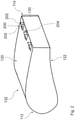
- the Figures 2 to 4 each show a profile section 132 with a blunt trailing edge 114, which can also be referred to as a flatback profile.
- the blunt trailing edge 114 has a specific trailing edge height 130 (in figure 2 marked) and defines a profile that is shortened in the direction of the profile depth.
- the profile section 132 has a blade chord between the leading edge 112 and the blunt trailing edge 114 .
- the profile section 132 corresponds to the cross-section of a rotor blade at any longitudinal point between the root region and the blade tip.
- This cross section is characterized in particular in that a surface orthogonal of this cross section is aligned essentially parallel to the longitudinal direction of the rotor blade.
- the profile section 132 has a suction side 120 and a pressure side 122 that define a rotor blade thickness.
- the suction side 120 is of essentially convex design.
- the pressure side 122 is essentially concave.
- the pressure side 122 and/or the suction side 120 can also be designed in a different shape, for example.
- FIG 2 shows a total of three vortex generators 200, which are essentially equally spaced from one another, each with a pair of vortex generators 202 on the suction side 120.
- the vortex generators 200 are here in a suction-side trailing edge region (in figure 2 not marked) extending from the blunt trailing edge 114 in Direction of the leading edge 120 extends.
- Such a suction-side trailing edge area can have an extension of less than 30%, in particular less than 20%, of the profile depth.
- the vortex generators 200 are essentially located in a near area on the suction side (in figure 2 not shown), which has an extension of less than or equal to 10% of the profile depth, starting from the blunt rear edge 114 in the direction of the front edge 112.
- the vortex generators 200 are located on the blunt trailing edge 114 such that the vortex generators 202 cantilever out from the blunt trailing edge 114 and the cantilever length 204 extends substantially from the blunt trailing edge 114 .
- the projection length 204 extends essentially parallel to the thickness of the rotor blade over the surface of the rotor blade.
- the overhang length 204 is less than 50% of the rear edge height 130.
- figure 3 includes in addition to the three suction-side vortex generators 200 - as above figure 2 described - three vortex generators 200, essentially equally spaced from one another, each with a pair of vortex generators 202 on the pressure side 122.
- the pressure side 122 like the suction side 120, has a pressure-side trailing edge area (in figure 3 not shown) with an extension of less than 30%, in particular less than 20% of the profile depth.
- the pressure-side close range (in figure 3 not shown) designated area of the pressure side has an extension of less than or equal to 10% of the profile depth, starting from the blunt rear edge 114 in the direction of the front edge 112.
- figure 3 shows that the vortex generators are arranged on the pressure side 122 at the blunt trailing edge 114, i.e. in the vicinity of the pressure side, so that the vortex generators 202 cantilever from the blunt trailing edge 114 and the cantilever length (in figure 3 not labeled) of these vortex generators 200 extending substantially from the blunt trail
- the in the figures 2 and 3 The flatback profiles illustrated have a substantially straight butt trailing edge 114 .
- the trailing edge height 130 (marked in figure 2 ) essentially corresponds to the rotor blade thickness in the corresponding profile section.
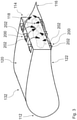
- shows figure 4 a suction-side trailing edge area with a suction-side transition area 206 adjacent to the trailing edge 114.
- the suction-side transition area 206 is here arranged between the suction-side profile contour 210 and the blunt trailing edge 114 and has a radius.
- the suction-side transition area 206 accordingly defines a rounding, which defines a transition from the suction-side profile contour 210 to the blunt trailing edge 114 .
- the rounding ie the suction-side transition area 206, is in particular a part of the suction-side trailing edge area.
- the vortex generators 202 are arranged directly in front of the transition area 206 .
- the trailing edge height 130 is more than 50% or more than 60% of the rotor blade thickness.
- the rounding defines an additional curvature in the trailing edge area. By positioning the vortex generators just in front of this additional curvature, the flow can follow the profile. As a result, a profile contour with an additional curvature in the area of the trailing edge can be optimally used, particularly aerodynamically. With this configuration, the trailing area and thus also the flow resistance can be efficiently reduced and a new profile contour in the area of the trailing edge can be used in an aerodynamically advantageous manner.
- the vortex generators 202 shown extend in the exemplary embodiments shown essentially perpendicularly to the surface of the rotor blade and describe an inhomogeneous geometry in the corresponding trailing edge region. In particular, angles greater than or less than 90° between the vortex generator 202 and the surface of the rotor blade are also possible. while in figure 2 Vortex generators 200 are arranged on the suction side 120, vortex generators 200 on the pressure side 122 are also possible as an alternative or in addition. Accordingly are also in figure 3 and or figure 4 Vortex generators 200 only on the suction side 120 or only on the pressure side 122 possible. In particular, the Figures 2-4 Vortex generators 202 shown in pairs next to one another can also be designed and/or arranged alternatively.
- Vortex generators 200 of this type Karman vortices and, in comparison to them, smaller disordered vortex pairs form in the dead water region in which wake turbulence occurs, which extract energy from the flow and thereby cause a high flow resistance.
- the Figures 3 and 4 show by way of example that by arranging the vortex generators 200 in the trailing edge region on the suction side and the pressure side, increased mixing 118 of a separation at the blunt trailing edge 114 with high-energy flow is achieved, and the size of the region of the wake turbulence 116 behind the blunt trailing edge 114 is thereby clearly illustrated can be reduced. In this way, in particular, the resistance can be reduced and thereby a glide ratio can be increased.
- the glide ratio can be maximally increased by an optimal configuration, preferably taking into account the variables influencing a lift coefficient and a drag coefficient.
- the glide ratio determines the quality of the blade and essentially also depends on the blade profile and the angle of attack. The higher the glide ratio, the lower the drag losses and the better the efficiency.
- a glide ratio of more than 20 can be achieved, particularly in the case of profiles with relatively thin trailing edges a glide ratio of more than 60 and/or in the case of thicker profiles a glide ratio of about 20-40.
- the targeted disruption of the homogeneous flow at the blunt trailing edge 114 as described above prevents or at least reduces the formation of acoustically relevant periodic vortex streets, so that noise emissions are reduced.
- figure 5 shows a view of the suction side 120 and in figure 6 The view shown shows the print page 122.
- the schematic representations of the rotor blade 108 in the figures 5 and 6 12 show a root region 124 at one end of the rotor blade 108 and a rotor blade tip 126 at the end opposite thereto.
- the distance between the rotor blade tip 126 in the root region 124 defines the rotor blade length.
- the rotor blade 108 has a deep chord.
- the profile depth is smaller at the rotor blade tip 126 .
- the profile depth initially increases starting from the root area 124 in the direction of the inner area of the blade and up to a middle area of the rotor blade 108 again significantly.
- one position of vortex generators 300 and 302 extends in figure 5 as well as 301 in figure 6 in a region from the middle region to the root region 124. This region also defines the blunt portion 208 having the blunt trailing edge 114 in the example shown here.
- the rotor blade 108 can have a number of profile sections which define the course of the profile of the rotor blade 108 .
- profile sections according to one of Figures 2-4 be arranged. Differently designed profile sections can preferably also be provided.
- the profile sections lying further in the direction of the blade tip 126 are free of a blunt trailing edge and in particular define an outer section 212 with an essentially closed profile.
- figure 5 shows an example of a first position of vortex generators 300 and a second position of vortex generators 302 on the suction side 120.
- the first position 300 is in a suction-side leading edge region that has an extent of less than 80%, in particular less than 70%, of the profile depth.
- the second position 302 can in particular be in the suction-side trailing edge area and/or the suction-side close-up area.
- the rear edge area on the suction side has an extension of less than 30%, in particular less than 20%, starting from the blunt rear edge 114 in the direction of the front edge.
- the near area on the suction side has an extent of less than or equal to 10% of the profile depth from the blunt rear edge 114 in the direction of the front edge.
- the rotor blade at the first position 300 can be free of vortex generators.
- the pressure side of the in figure 5 rotor blade shown may preferably be free of vortex generators or equivalent figure 6 be designed so that vortex generators are provided both on the pressure side and on the suction side.
- figure 6 shows an example of a position of vortex generators 301 on the pressure side 122.
- This position 301 is located in a suction-side leading edge area that has an extent of less than 80%, in particular less than 70%, of the profile depth.
- leading edge area which has an extent of less than 80%, in particular less than 70% of the profile depth, is free of vortex generators.
- a further position of vortex generators can be provided in the pressure-side leading edge area.
Abstract
Die Erfindung betriff ein Rotorblatt (108) für einen Rotor (106), insbesondere einer Windenergieanlage (100), mit einer sich zwischen einem Wurzelbereich (124) und einer Rotorblattspitze (126) einstellenden Rotorblattlänge, einer sich zwischen einer Vorderkante (112) und einer stumpfen Hinterkante (114) einstellenden Rotorblatttiefe, einer sich zwischen einer Druckseite (122) und einer Saugseite (120) einstellenden Rotorblattdicke, einen sich auf der Saugseite (120) erstreckenden, saugseitigen Hinterkantenbereich und/oder einen sich auf der Druckseite (122) erstreckenden, druckseitigen Hinterkantenbereich, wobei sich der saugseitige Hinterkantenbereich und/oder der druckseitige Hinterkantenbereich ausgehend von der stumpfen Hinterkante (114) in Richtung der Vorderkante (112) mit einer Erstreckung von kleiner 30 %, insbesondere kleiner 20 %, der Profiltiefe erstreckt, und wobei der saugseitige Hinterkantenbereich und/oder der druckseitige Hinterkantenbereich mindestens einen Wirbelgenerator (200) aufweist.The invention relates to a rotor blade (108) for a rotor (106), in particular a wind energy plant (100), with a rotor blade length between a root area (124) and a rotor blade tip (126), a rotor blade length between a front edge (112) and a a blunt trailing edge (114) adjusting rotor blade depth, a rotor blade thickness adjusting between a pressure side (122) and a suction side (120), a suction-side trailing edge area extending on the suction side (120) and/or a trailing edge area extending on the pressure side (122), pressure-side trailing edge area, with the suction-side trailing edge area and/or the pressure-side trailing edge area extending from the blunt trailing edge (114) in the direction of the leading edge (112) with an extent of less than 30%, in particular less than 20%, of the profile depth, and wherein the suction-side Trailing edge area and/or the pressure-side trailing edge area has at least one vortex gene ator (200).
Description
Die Erfindung betrifft ein Rotorblatt für eine Windenergieanlage, einen Rotor für eine Windenergieanlage, ein Bauwerk und eine Windenergieanlage mit einem Rotor und/oder einem Bauwerk.The invention relates to a rotor blade for a wind power plant, a rotor for a wind power plant, a structure and a wind power plant with a rotor and/or a structure.
Windenergieanlagen weisen einen Rotor mit mindestens einem, zwei oder mehreren Rotorblättern, vorzugsweise drei Rotorblättern, auf und sind ausgebildet, um aus kinetischer Windenergie mechanische Rotationsenergie und aus dieser elektrische Energie zu erzeugen. Derartige Windenergieanlagen sind allgemein bekannt und umfassen in der Regel eine Gondel, an der der Rotor angeordnet ist, und einen Turm, auf dem die Gondel mit dem Rotor um eine im Wesentlichen vertikal ausgerichtete Achse drehbar angeordnet ist.Wind energy installations have a rotor with at least one, two or more rotor blades, preferably three rotor blades, and are designed to generate mechanical rotational energy from kinetic wind energy and electrical energy from this. Such wind energy installations are generally known and generally comprise a nacelle on which the rotor is arranged and a tower on which the nacelle with the rotor is arranged so as to be rotatable about an essentially vertically aligned axis.
Windenergieanlagen sind in der Regel als sogenannte Horizontalachsen-Windenergieanlagen ausgebildet, die einen Rotor mit einer im Wesentlichen horizontalen Achse umfassen, dessen Rotorblätter sich in einer Ebene im Wesentlichen senkrecht zum Wind drehen. Derartige Horizontalachsen-Windenergieanlagen nutzen zur Wandlung der kinetischen Windenergie in die mechanische Rotationsenergie das aerodynamische Prinzip des Auftriebs. Hierbei bildet ein Profil eines Rotorblatts eine Saugseite und eine Druckseite aus, sodass bei Umströmung des Profils mit bewegter Luft auf der Saugseite gegenüber der Druckseite ein Unterdruck entsteht. Der daraus resultierende Druckunterschied zwischen der Druckseite und der Saugseite führt zu einem aerodynamischen Auftrieb. Der Auftrieb ist hierbei beispielsweise von einem Anstellwinkel der Rotorblätter abhängig.Wind turbines are generally designed as so-called horizontal-axis wind turbines, which include a rotor with an essentially horizontal axis, the rotor blades of which rotate in a plane essentially perpendicular to the wind. Such horizontal-axis wind turbines use the aerodynamic principle of lift to convert the kinetic wind energy into mechanical rotational energy. In this case, a profile of a rotor blade forms a suction side and a pressure side, so that when moving air flows around the profile, a negative pressure is created on the suction side compared to the pressure side. The resulting pressure difference between the pressure side and the suction side leads to an aerodynamic lift. In this case, the lift is dependent, for example, on an angle of attack of the rotor blades.
Bekannte Rotorblätter sind dahingehend nachteilig, dass die anliegende Luftströmung, insbesondere an einer Saugseite, abreißt und sich ein sogenanntes "Totwassergebiet" mit einer abgelösten Strömung bildet. Insbesondere bei größeren Anstellwinkeln kann die Strömung nicht mehr glatt an einem Profil eines Rotorblatts anliegen und reißt ab. Das Totwassergebiet mindert den Auftrieb des Rotorblatts und bremst das Rotorblatt ab, indem es dessen Widerstand erhöht. Dadurch wird ein Wirkungsgrad des Rotors und somit auch ein Ertrag einer Windenergieanlage reduziert.Known rotor blades are disadvantageous in that the adjacent air flow, in particular on a suction side, breaks off and a so-called forms a "dead water area" with a separated flow. Especially with larger angles of attack, the flow can no longer rest smoothly against a profile of a rotor blade and breaks off. The dead water area reduces the lift of the rotor blade and decelerates the rotor blade by increasing its drag. This reduces the efficiency of the rotor and thus also the yield of a wind energy installation.
Zur Verbesserung der aerodynamischen Eigenschaften von Rotorblättern und zur Steigerung der Effizienz sind unterschiedliche Lösungen bekannt. Beispielsweise ist es bekannt Vortexgeneratoren in einem Bereich zwischen 10 % und 60 % der Profilsehnenlänge ausgehend von einer Nasenkante des Profils vorzusehen. Die Vortexgeneratoren dienen dazu, über einer Oberfläche des Rotortblattes lokale Regionen turbulenter Luftströmungen zu erzeugen, um eine Erhöhung der Resistenz gegen Strömungsablösungen zu bewirken. Hierzu verwirbeln Wirbelgeneratoren eine wandnahe Strömung am Rotorblatt, in dessen Folge sich der Impulsaustausch zwischen wandnahen und wandfernen Strömungsschichten stark erhöht und die Strömungsgeschwindigkeiten in der wandnahen Grenzschicht zunehmen. Hierbei wird durch die Vortexgeneratoren selbst Widerstand erzeugt, sodass der Ertrag der Windenergieanlage nicht oder nur geringfügig gesteigert werden kann. Nachteilig an dieser Anordnung der Vortexgeneratoren ist zudem, dass diese laute Geräusche erzeugen.Various solutions are known for improving the aerodynamic properties of rotor blades and for increasing efficiency. For example, it is known to provide vortex generators in an area between 10% and 60% of the chord length of the profile, starting from a leading edge of the profile. The vortex generators serve to generate local regions of turbulent air currents over a surface of the rotor blade in order to increase the resistance to flow separation. For this purpose, vortex generators swirl a flow close to the wall on the rotor blade, as a result of which the momentum exchange between the flow layers close to the wall and those farther away from the wall increases significantly and the flow velocities in the boundary layer close to the wall increase. In this case, resistance is generated by the vortex generators themselves, so that the yield of the wind turbine cannot be increased or can only be increased slightly. Another disadvantage of this arrangement of the vortex generators is that they produce loud noises.
Es ist auch bekannt, Rotorblätter mit einer zumindest teilweisen stumpfen Hinterkante im Innenbereich zu verwenden. Derartige Rotorblätter sind insbesondere dahingehend nachteilig, dass im Bereich der stumpfen Hinterkante die Auftriebsleistung aufgrund der geringeren Blatttiefe reduziert ist und sich zudem in diesem Bereich Wirbel in Form einer sogenannten Kärmänschen Wirbelstraße bilden können, die einen erhöhten Luftwiderstand und eine erhöhte Geräuschemission zur Folge haben.It is also known to use rotor blades with an at least partially blunt trailing edge in the interior. Such rotor blades are particularly disadvantageous in that in the area of the blunt trailing edge, the lift performance is reduced due to the lower blade depth and vortices can also form in this area in the form of a so-called Karman vortex street, which results in increased air resistance and increased noise emissions.
Ferner sind zur Reduktion des Widerstands Modifikationen von flachen Profil-Hinterkanten durch Aushöhlen oder durch die Einbringung von Ausschnitten oder Vertiefungen bekannt. In
Auch die Verwendung zusätzlicher Splitter-Platten, die ausgebildet sind, um eine alternierende Wirbelstraße hinter einem stumpfen Körper in zwei stationäre Wirbel aufzuteilen und dadurch den Widerstand zu reduzieren, sind bekannt. Eine zusätzliche Splitterplatte an einem Rotorblatt hat jedoch eine größere Rotorblatttiefe zur Folge, die sich negativ auf die Transportabmessungen auswirkt und durch die größere Rotorblatttiefe erhöhte Anlagenlasten verursacht.It is also known to use additional splitter plates designed to split an alternating vortex street behind a blunt body into two stationary vortices and thereby reduce drag. However, an additional splinter plate on a rotor blade results in a greater rotor blade depth, which has a negative effect on the transport dimensions and causes increased system loads due to the greater rotor blade depth.
Die existierenden Vorrichtungen zur Verbesserung der aerodynamischen Eigenschaften von Rotorblättern und Steigerung der Effizienz bieten verschiedene Vorteile, jedoch sind weitere Verbesserungen wünschenswert.Existing devices for improving the aerodynamic properties of rotor blades and increasing efficiency offer various advantages, but further improvements are desirable.
Windenergieanlagen können zudem standortabhängigen Rahmenbedingungen, wie zum Beispiel hinsichtlich eines nicht zu überschreitenden Schallpegels, unterliegen. Um den Schallpegel zu reduzieren, werden die Windenergieanlagen häufig in einem schallreduzierten Betriebsmodus regelmäßig mit einer reduzierten Nennrotordrehzahl gegenüber dem leistungsoptimierten Betriebsmodus betrieben.Wind turbines can also be subject to site-dependent framework conditions, such as with regard to a noise level that should not be exceeded. In order to reduce the noise level, the wind turbines are often operated in a noise-reduced operating mode with a reduced nominal rotor speed compared to the power-optimized operating mode.
Das Deutsche Patent- und Markenamt hat in der Prioritätsanmeldung zu vorliegender Anmeldung folgenden Stand der Technik recherchiert:
Es ist daher eine Aufgabe der vorliegenden Erfindung, ein Rotorblatt für eine Windenergieanlage, einen Rotor für eine Windenergieanlage, ein Bauwerk und eine Windenergieanlage mit einem Rotor und/oder mit einem Bauwerk bereitzustellen, die einen oder mehrere der genannten Nachteile vermindern oder beseitigen. Es ist insbesondere eine Aufgabe der Erfindung, eine Lösung bereitzustellen, die Wirksamkeit eines Rotorblatts einer Windenergieanlage für eine hohe Anlagenwirtschaftlichkeit weiter zu steigern und gleichzeitig eine Reduktion der Schallemission zu bewirken. Insbesondere ist es eine Aufgabe aerodynamische Eigenschaften eines Rotorblatts für eine Windenergieanlage, eines Rotors für eine Windenergieanlage, eines Bauwerks und einer Windenergieanlage mit einem Rotor und/oder mit einem Bauwerk zu verbessern, ohne strukturelle Eigenschaften derselben zu verschlechtern.It is therefore an object of the present invention to provide a rotor blade for a wind turbine, a rotor for a wind turbine, a structure and a wind turbine with a rotor and/or with a structure that reduce or eliminate one or more of the disadvantages mentioned. In particular, it is an object of the invention to provide a solution for further increasing the effectiveness of a rotor blade of a wind energy installation for high installation efficiency and at the same time bringing about a reduction in noise emissions. In particular, it is an object aerodynamic properties of a rotor blade for a wind turbine, of a rotor for a wind turbine, a structure and a wind turbine with a rotor and/or with a structure without impairing structural properties of the same.
Gemäß einem ersten Aspekt wird diese Aufgabe gelöst durch ein Rotorblatt für eine Windenergieanlage mit einer sich zwischen einem Wurzelbereich und einer Rotorblattspitze einstellenden Rotorblattlänge, einer sich zwischen einer Vorderkante und einer stumpfen Hinterkante einstellenden Rotorblatttiefe, einer sich zwischen einer Druckseite und einer Saugseite einstellenden Rotorblattdicke, einen sich auf der Saugseite erstreckenden, saugseitigen Hinterkantenbereich und/oder einen sich auf der Druckseite erstreckenden, druckseitigen Hinterkantenbereich, wobei sich der saugseitige Hinterkantenbereich und/oder der druckseitige Hinterkantenbereich ausgehend von der stumpfen Hinterkante in Richtung der Vorderkante mit einer Erstreckung von kleiner 30 %, insbesondere kleiner 20 %, der Profiltiefe erstreckt, und wobei der saugseitige Hinterkantenbereich und/oder der druckseitige Hinterkantenbereich mindestens einen Wirbelgenerator aufweist.According to a first aspect, this object is achieved by a rotor blade for a wind turbine with a rotor blade length set between a root area and a rotor blade tip, a rotor blade depth set between a leading edge and a blunt trailing edge, a rotor blade thickness set between a pressure side and a suction side, a a suction-side trailing edge area extending on the suction side and/or a pressure-side trailing edge area extending on the pressure side, with the suction-side trailing edge area and/or the pressure-side trailing edge area starting from the blunt trailing edge in the direction of the leading edge with an extent of less than 30%, in particular less than 20% of the profile depth, and wherein the suction-side trailing edge area and/or the pressure-side trailing edge area has at least one vortex generator.
Der Erfindung liegt die Erkenntnis zugrunde, dass das Totwassergebiet, in dem Nachlaufturbulenzen entstehen, einen großen Teil des aerodynamischen Widerstands stumpfer Körper verursacht. Die Erfinder haben herausgefunden, dass sich in diesem Totwassergebiet eine Kármánsche Wirbelstraße, also periodisch ablösende Wirbelpaare, und im Vergleich dazu kleinere ungeordnete Wirbelpaare bilden, sodass der Strömung Energie entzogen und dadurch ein hoher Strömungswiderstand verursacht wird.The invention is based on the finding that the dead water area, in which wake turbulence occurs, causes a large part of the aerodynamic drag of blunt bodies. The inventors found out that in this stagnant water area, a Kármán vortex street, i.e. periodically shedding vortex pairs, and, in comparison, smaller disordered vortex pairs form, so that energy is withdrawn from the flow and this causes a high flow resistance.
Das Rotorblatt erstreckt sich insbesondere in Richtung der Rotorblattlänge, die Rotorblatttiefe und die Rotorblattdicke. In Richtung der Rotorblattlänge erstreckt sich das Rotorblatt zwischen einem Wurzelbereich und einer Rotorblattspitze. Die Rotorblatttiefe ist insbesondere im Wesentlichen orthogonal zu der Rotorblattlänge ausgerichtet und erstreckt sich zwischen der Vorderkante und der stumpfen Hinterkante. Im Betrieb ist die Rotorblatttiefe im Wesentlichen parallel zu einer Anströmrichtung des Rotorblatts ausgerichtet. Insbesondere im Wesentlichen orthogonal zu der Richtung der Rotorblattlänge und der Rotorblatttiefe erstreckt sich das Rotorblatt in Richtung der Rotorblattdicke. Die Rotorblatttiefe und die Rotorblattdicke definieren insbesondere an im Wesentlichen jeder Position entlang der Rotorblattlänge ein aerodynamisches Profil. Zur Effizienzsteigerung weist das Rotorblatt mindestens einen Wirbelgenerator auf, der in oder an einem Bereich der stumpfen Hinterkante auf der Druckseite und/oder der Saugseite angeordnet ist. Dieser als Hinterkantenbereich bezeichnete Bereich erstreckt sich ausgehend von der stumpfen Hinterkante des Rotorblatts in Richtung der Vorderkante. Der Hinterkantenbereich hat hierbei eine Erstreckung kleiner 30 %, insbesondere kleiner 20 %, der Profiltiefe.The rotor blade extends in particular in the direction of the rotor blade length, the rotor blade depth and the rotor blade thickness. In the direction of the length of the rotor blade, the rotor blade extends between a root area and a rotor blade tip. In particular, the rotor blade chord is substantially orthogonal to the rotor blade length and extends between the leading edge and the blunt trailing edge. During operation, the rotor blade depth is aligned essentially parallel to an inflow direction of the rotor blade. In particular, the rotor blade extends essentially orthogonally to the direction of the rotor blade length and the rotor blade depth in the direction of the rotor blade thickness. The rotor blade depth and the In particular, rotor blade thicknesses define an aerodynamic profile at substantially every position along the rotor blade length. To increase efficiency, the rotor blade has at least one vortex generator, which is arranged in or on a region of the blunt trailing edge on the pressure side and/or the suction side. This area, referred to as the trailing edge area, extends from the blunt trailing edge of the rotor blade in the direction of the leading edge. In this case, the trailing edge area has an extent of less than 30%, in particular less than 20%, of the profile depth.
Der mindestens eine Wirbelgenerator kann auf der stumpfen Hinterkante, insbesondere auf einer Kante, die gebildet ist durch die stumpfe Hinterkante und die Saugseite, oder in einem Bereich vor der stumpfen Hinterkante zwischen 70% und 100%, insbesondere zwischen 80% und 100%, der Profiltiefe von der Vorderkante aus gemessen angeordnet sein.The at least one vortex generator can be located on the blunt trailing edge, in particular on an edge formed by the blunt trailing edge and the suction side, or in an area in front of the blunt trailing edge between 70% and 100%, in particular between 80% and 100% Tread depth measured from the front edge.
Die Saugseite des Rotorblattes kann insbesondere einer Fläche des Rotorblattes entsprechen, die im Betrieb der Windenergieanlage einen Auftrieb erzeugt und somit bei Luftumströmung die Drehung eines Rotors, an dem das Rotorblatt befestigt ist, antreibt. Die Druckseite kann insbesondere der Saugseite gegenüberliegen. Bei Luftumströmung bildet sich insbesondere sowohl an der Saugseite als auch an der Druckseite eine Grenzschicht.The suction side of the rotor blade can in particular correspond to a surface of the rotor blade that generates lift during operation of the wind turbine and thus drives the rotation of a rotor to which the rotor blade is attached when the air flows around it. The pressure side can in particular be opposite the suction side. When air flows around, a boundary layer forms in particular both on the suction side and on the pressure side.
Unter einer stumpfen Hinterkante kann insbesondere verstanden werden, dass das Rotorblatt an seinem hinteren Ende, also an der Hinterkante, noch eine spezifische Hinterkantenhöhe aufweist und demnach im Wesentlichen nicht spitz zuläuft.A blunt trailing edge can be understood in particular to mean that the rotor blade still has a specific trailing edge height at its rear end, that is to say at the trailing edge, and accordingly does not essentially taper to a point.
Insbesondere kann ein Profilverlauf des Rotorblatts eine Anzahl an Profilschnitten aufweisen, die die Außenkontur des Rotorblatts definieren. Ein Rotorblatt umfasst in der Regel eine Mehrzahl unterschiedlicher Profilschnitte. Die Profilschnitte sollen an den verschiedenen Radiuspositionen eines Rotorblatts einen im Wesentlichen aerodynamisch optimalen Strömungsverlauf ermöglichen. Insbesondere kann mindestens ein Profilschnitt der mehreren Profilschnitte die stumpfe Hinterkante aufweisen. Insbesondere kann die stumpfe Hinterkante eine Hinterkantenhöhe von mehr als 0,5 % einer Profilschnitttiefe des Profilschnitts aufweisen. Bevorzugt können weitere Profilschnitte, insbesondere die weiter in Richtung der Blattspitze liegenden Profilschnitte des Rotorblattes frei von einer stumpfen Hinterkante sein.In particular, a profile of the rotor blade can have a number of profile sections that define the outer contour of the rotor blade. A rotor blade usually includes a number of different profile sections. The profile sections are intended to enable a flow pattern that is essentially aerodynamically optimal at the various radius positions of a rotor blade. In particular, at least one profile section of the plurality of profile sections can have the blunt trailing edge. In particular, the blunt trailing edge can have a trailing edge height of more than 0.5% of a profile section depth of the profile section exhibit. Further profile sections, in particular the profile sections of the rotor blade lying further in the direction of the blade tip, can preferably be free of a blunt trailing edge.
Durch das Anordnen des mindestens einen Wirbelgenerators in dem Hinterkantenbereich auf der Saugseite und/oder der Druckseite kann eine erhöhte Durchmischung einer Ablösung an der stumpfen Hinterkante mit energiereicher Strömung erzielt werden und dadurch eine Größe des Totwassergebiets, in dem Nachlaufturbulenzen entstehen, hinter stumpfen Körpern deutlich reduziert werden. Insbesondere kann diese Anordnung der Wirbelgeneratoren die Entstehung der ungeordneten Wirbel, deren Drehachse im Wesentlichen senkrecht zu einer Ebene der stumpfen Hinterkante ausgerichtet ist, verhindern oder zumindest reduzieren. Dadurch steigt der Druck im Bereich hinter dem Profil deutlich an, und der Strömungswiderstand wird, insbesondere durch die Verkleinerung des Ablösegebietes hinter dem Profil, reduziert. Zwar wird auch ein Reibungswiderstand des Profils durch zusätzliche Strömungsflächen des mindestens einen Wirbelgenerators leicht erhöht. Aufgrund des erzielbaren Druckwiderstands kann durch den mindestens einen Wirbelgenerator im Hinterkantenbereich jedoch eine Gesamtwiderstandsreduktion erreicht werden. Gleichzeitig kann durch den mindestens einen Wirbelgenerator eine Umströmung von dicken Profilen, insbesondere im Wurzelbereich von Rotorblättern von Windkraftanlagen, optimiert werden. Mittels des mindestens einen Wirbelgenerators kann folglich die Leistung eines Rotorblattes mit einer stumpfen Hinterkante, insbesondere im Bereich der stumpfen Hinterkante, verbessert werden.By arranging the at least one vortex generator in the trailing edge area on the suction side and/or the pressure side, increased mixing of a detachment at the blunt trailing edge with high-energy flow can be achieved and the size of the dead water area, in which wake turbulence occurs, behind blunt bodies can be significantly reduced will. In particular, this arrangement of the vortex generators can prevent or at least reduce the formation of disordered vortices, the axis of rotation of which is aligned essentially perpendicular to a plane of the blunt trailing edge. As a result, the pressure in the area behind the profile increases significantly and the flow resistance is reduced, in particular due to the reduction in the separation area behind the profile. A frictional resistance of the profile is also slightly increased by additional flow surfaces of the at least one vortex generator. Due to the achievable pressure resistance, however, an overall reduction in resistance can be achieved by the at least one vortex generator in the trailing edge area. At the same time, the flow around thick profiles, in particular in the root area of rotor blades of wind turbines, can be optimized by the at least one vortex generator. The performance of a rotor blade with a blunt trailing edge, in particular in the area of the blunt trailing edge, can consequently be improved by means of the at least one vortex generator.
Ein weiterer Vorteil der vorliegenden Lösung besteht darin, dass durch gezielte Störung einer homogenen Strömung an der stumpfen Hinterkante bzw. hinter der stumpfen Hinterkante des Profils eine Ausbildung alternierender Nachlaufwirbel unterbunden werden kann, sodass sich keine akustisch relevanten periodischen Wirbelstraßen bilden und der Strömungswiderstand am Profilschnitt reduziert wird. Dadurch kann eine Geräuschemission reduziert werden.Another advantage of the present solution is that the formation of alternating wake vortices can be prevented by targeted disruption of a homogeneous flow at the blunt trailing edge or behind the blunt trailing edge of the profile, so that no acoustically relevant periodic vortices are formed and the flow resistance at the profile section is reduced will. As a result, noise emissions can be reduced.
Demnach können durch das Anordnen des mindestens einen Wirbelgenerators in dem Hinterkantenbereich auf der Saugseite und/oder der Druckseite die aerodynamischen Eigenschaften des Rotorblatts, insbesondere an einem Innenblatt verbessert werden, ohne strukturelle Eigenschaften zu verschlechtern. Vorteilhaft ist ferner, dass durch die vorgeschlagene Lösung insgesamt eine Effizienz einer Windenergieanlage und dadurch einen Jahresertrag gesteigert werden kann.Accordingly, by arranging the at least one vortex generator in the trailing edge area on the suction side and / or the pressure side aerodynamic properties of the rotor blade, in particular on an inner blade, can be improved without impairing structural properties. It is also advantageous that the proposed solution can increase the overall efficiency of a wind energy installation and thus an annual yield.
Die Anordnung des mindestens einen Wirbelgenerators an dem saugseitigen und/oder druckseitigen Hinterkantenbereich stellt auch insbesondere eine kostengünstige Maßnahme dar, um die Leistung und die akustischen Eigenschaften des Rotorblatts, insbesondere an der stumpfen Hinterkante, zu verbessern. Insbesondere kann dadurch der strukturelle Aufbau der Rotorblätter im Bereich der stumpfen Hinterkante und/oder eine strukturelle Auslegung der Rotorblätter und insbesondere die Herstellung vereinfacht werden, um Kosten zu reduzieren. Dadurch kann insbesondere eine Komplexität bisheriger Herstellungsprozesse von Rotorblättern reduziert werden. Beispielsweise können durch die vorgeschlagene Lösung Kontureinleger zur Erreichung einer exakt scharfen Hinterkante bei der Herstellung einer Hinterkante weggelassen werden, sodass Kosten eingespart werden können.The arrangement of the at least one vortex generator on the suction-side and/or pressure-side trailing edge area also represents a cost-effective measure to improve the performance and the acoustic properties of the rotor blade, in particular on the blunt trailing edge. In this way, in particular, the structural design of the rotor blades in the area of the blunt trailing edge and/or a structural design of the rotor blades and in particular the manufacture can be simplified in order to reduce costs. In this way, in particular, the complexity of previous manufacturing processes for rotor blades can be reduced. For example, the proposed solution can be used to omit contour inserts to achieve an exactly sharp trailing edge when producing a trailing edge, so that costs can be saved.
Insbesondere können vorstehend beschriebene Vorteile erzielt werden, ohne eine Außenabmessung, insbesondere eine Rotorblattlänge und eine Rotorblatttiefe, des Rotorblatts zu ändern. Beispielsweise kann durch diese Lösung ein Profilschnitt mit der stumpfen Hinterkante weiter außen, also weiter in Richtung der Blattspitze, am Rotorblatt und/oder höhere Profilabschnitte mit der stumpfen Hinterkante verwendet werden ohne dadurch eine Schallemission zu erhöhen, um weitere strukturelle Vorteile erzielen zu können. Durch den Gewinn an relativer Dicke weiter außen am Rotorblatt lassen sich strukturell vorteilhaftere Rotorblattgeometrien realisieren. Dadurch ist der Einsatz von leichteren und kostengünstigeren Rotorblättern möglich.In particular, the advantages described above can be achieved without changing an external dimension, in particular a rotor blade length and a rotor blade depth, of the rotor blade. For example, with this solution, a profile section with the blunt trailing edge further outwards, i.e. further in the direction of the blade tip, on the rotor blade and/or higher profile sections with the blunt trailing edge can be used without increasing noise emission in order to be able to achieve further structural advantages. Structurally more advantageous rotor blade geometries can be realized due to the gain in relative thickness further out on the rotor blade. This enables the use of lighter and more cost-effective rotor blades.
Die vorstehend genannten Vorteile können durch die vorgeschlagene Lösung insbesondere betriebslastneutral erreicht werden.The advantages mentioned above can be achieved by the proposed solution, in particular in a manner that is neutral in terms of the operating load.
Das hier beschriebene Rotorblatt ist nicht auf den Einsatz bei Windenergieanlagen beschränkt, auch wenn es hier besonders vorteilhaft und auf wirtschaftliche Art und Weise eingesetzt werden kann. Vielmehr kann das hier beschriebene Rotorblatt auch bei Propellern, Hubschrauberrotoren oder anderen Strömungsmaschinen eingesetzt werden. So kann durch das Anordnen des mindestens einen Wirbelgenerators in dem Hinterkantenbereich auf der Saugseite und/oder der Druckseite beispielsweise auch die Strömung an dicken Profilen von Probellern, Hubschrauberrotoren oder anderen Strömungsmaschinen optimiert werden.The rotor blade described here is not limited to use in wind turbines, even if it is particularly advantageous and economical here and manner can be used. Rather, the rotor blade described here can also be used in propellers, helicopter rotors or other turbomachines. By arranging the at least one vortex generator in the trailing edge area on the suction side and/or the pressure side, for example, the flow on thick profiles of propellors, helicopter rotors or other turbomachines can also be optimized.
Besonders bevorzugt können mindestens zwei, drei oder mehrere Wirbelgeneratoren an dem saugseitigen Hinterkantenbereich und/oder dem druckseitigen Hinterkantenbereich angeordnet sein. Insbesondere bevorzugt können die mindestens zwei, drei oder mehreren Wirbelgeneratoren beabstandet voneinander und/oder in Richtung der Rotorblatttiefe im Wesentlichen gleichmäßig verteilt und/oder im Wesentlichen an der stumpfen Hinterkante oder in einem im Wesentlichen identischen Abstand zur stumpfen Hinterkante angeordnet sein. Durch die Anordnung von mindestens zwei, drei oder mehreren Wirbelgeneratoren kann sowohl der Widerstand als auch die Geräuschemission des Rotorblatts weiter reduziert werden. Gleichzeitig kann eine Umströmung von dicken Profilen, insbesondere im Wurzelbereich von Rotorblättern von Windkraftanlagen, weiter optimiert werden. Dadurch kann die Leistung eines Rotorblatts weiter verbessert werden.Particularly preferably, at least two, three or more vortex generators can be arranged on the suction-side trailing edge area and/or the pressure-side trailing edge area. Particularly preferably, the at least two, three or more vortex generators can be spaced apart and/or distributed substantially evenly in the direction of the rotor blade chord and/or arranged substantially on the blunt trailing edge or at a substantially identical distance from the blunt trailing edge. By arranging at least two, three or more vortex generators, both the resistance and the noise emission of the rotor blade can be further reduced. At the same time, a flow around thick profiles, in particular in the root area of rotor blades of wind turbines, can be further optimized. As a result, the performance of a rotor blade can be further improved.
Besonders bevorzugt ist es, wenn das Rotorblatt einen sich auf der Saugseite erstreckenden, saugseitigen Hinterkantenbereich und einen sich auf der Druckseite erstreckenden, druckseitigen Hinterkantenbereich, wobei sich der saugseitige Hinterkantenbereich und der druckseitige Hinterkantenbereich ausgehend von der stumpfen Hinterkante in Richtung der Vorderkante mit einer Erstreckung von kleiner 30 %, insbesondere kleiner 20 %, der Profiltiefe erstreckt, und wobei der saugseitige Hinterkantenbereich und der druckseitige Hinterkantenbereich mindestens einen Wirbelgenerator aufweist.It is particularly preferred if the rotor blade has a suction-side trailing edge area that extends on the suction side and a pressure-side trailing edge area that extends on the pressure side, with the suction-side trailing edge area and the pressure-side trailing edge area extending from the blunt trailing edge in the direction of the leading edge with an extension of less than 30%, in particular less than 20%, of the profile depth, and wherein the suction-side trailing edge area and the pressure-side trailing edge area have at least one vortex generator.
Insbesondere bevorzugt ist es, wenn das Rotorblatt einen sich auf der Saugseite erstreckenden, saugseitigen Hinterkantenbereich, wobei sich der saugseitige Hinterkantenbereich ausgehend von der stumpfen Hinterkante in Richtung der Vorderkante mit einer Erstreckung von kleiner 30 %, insbesondere kleiner 20 %, der Profiltiefe erstreckt, und wobei der saugseitige Hinterkantenbereich mindestens einen Wirbelgenerator aufweist. Vorzugsweise kann das Rotorblatt einen sich auf der Druckseite erstreckenden, druckseitigen Hinterkantenbereich aufweisen, wobei sich der druckseitige Hinterkantenbereich ausgehend von der stumpfen Hinterkante in Richtung der Vorderkante mit einer Erstreckung von kleiner 30 %, insbesondere kleiner 20 %, der Profiltiefe erstreckt, und wobei der druckseitige Hinterkantenbereich frei von Wirbelgeneratoren ist.It is particularly preferred if the rotor blade has a suction-side trailing edge area that extends on the suction side, with the suction-side trailing edge area extending from the blunt trailing edge in the direction of the leading edge with an extent of less than 30%, in particular less than 20%. of the profile depth, and wherein the suction-side trailing edge region has at least one vortex generator. The rotor blade can preferably have a pressure-side trailing edge area that extends on the pressure side, with the pressure-side trailing edge area extending from the blunt trailing edge in the direction of the leading edge with an extent of less than 30%, in particular less than 20%, of the profile depth, and with the pressure-side trailing edge area is free of vortex generators.
Eine bevorzugte Fortbildung des Rotorblatts zeichnet sich dadurch aus, dass der Wirbelgenerator derart ausgebildet ist, dass der saugseitige Hinterkantenbereich und/oder der druckseitige Hinterkantenbereich eine inhomogene Geometrie aufweist, sodass an der stumpfen Hinterkante ausbildende Wirbelgebiete unterbunden oder abgeschwächt werden. Dadurch kann das Nachlaufgebiet und folglich auch der Strömungswiderstand effizient verkleinert werden.A preferred development of the rotor blade is characterized in that the vortex generator is designed in such a way that the suction-side trailing edge area and/or the pressure-side trailing edge area has an inhomogeneous geometry, so that vortex areas forming on the blunt trailing edge are suppressed or weakened. As a result, the wake area and consequently also the flow resistance can be efficiently reduced.
Insbesondere können die Wirbelgeneratoren als eine Erhöhung und/oder eine Vertiefung und/oder eine Ausnehmung einer Oberfläche des Hinterkantenbereichs ausgebildet sein. Unter einer inhomogenen Geometrie kann insbesondere verstanden werden, dass eine Oberfläche Unregelmäßigkeiten und bevorzugt eine gewisse Oberflächenrauhigkeit aufweist.In particular, the vortex generators can be designed as an elevation and/or a depression and/or a recess of a surface of the trailing edge region. An inhomogeneous geometry can be understood in particular as meaning that a surface has irregularities and preferably a certain surface roughness.
Es ist bevorzugt, dass der Wirbelgenerator einen Vortexgenerator, insbesondere ein Paar an Vortexgeneratoren, aufweist, wobei vorzugsweise der Vortexgenerator von der stumpfen Hinterkante auskragt, wobei vorzugsweise der Vortexgenerator als Vane-Vortexgenerator oder als Wishbone-Vortexgenerator ausgebildet ist.It is preferred that the vortex generator has a vortex generator, in particular a pair of vortex generators, with the vortex generator preferably projecting from the blunt trailing edge, with the vortex generator preferably being designed as a vane vortex generator or as a wishbone vortex generator.
Insbesondere können die Vortexgeneratoren demnach flügelartig, deltaförmig, hufeisenförmig oder entsprechend einer alternativen Geometrie ausgebildet sein.In particular, the vortex generators can therefore be embodied in the form of wings, deltas, horseshoes or in accordance with an alternative geometry.
Unter einem Vortexgenerator kann insbesondere eine Art Störkörper verstanden werden, der auf der Profiloberfläche angebracht werden kann. Beispielsweise kann es sich hierbei um Plättchen handeln, die insbesondere in einem bestimmten Winkel zueinander angeordnet sein können, um die gewünschte Wirbelbildung in bestimmter Weise zu erhöhen, um dadurch eine Durchmischung der Ablösung zu erzielen und das Nachlaufgebiet zu reduzieren.A vortex generator can be understood in particular as a type of disturbing body that can be attached to the profile surface. For example, these can be small plates, which can be arranged at a specific angle to one another in order to increase the desired formation of vortices in a specific way, in order to achieve thorough mixing of the detachment and to reduce the wake area.
Der Vortexgenerator kann beispielsweise stoffschlüssig mit einer Oberfläche verbunden, insbesondere auf der Oberfläche aufgeklebt werden. Dadurch kann ein Rotorblatt besonders einfach umgerüstet bzw. mit Vortexgeneratoren ausgestattet werden.The vortex generator can, for example, be materially connected to a surface, in particular glued to the surface. As a result, a rotor blade can be retrofitted or equipped with vortex generators in a particularly simple manner.
Bevorzugt kann der mindestens eine Wirbelgenerator und/oder der Vortexgenerator, insbesondere die mehreren Wirbelgeneratoren und/oder die mehreren Vortexgeneratoren, ausgebildet sein um gleichgerichtete (Co-Rotating) oder entgegengesetzt gerichtete (Counter-Rotating) Wirbelpaare zu erzeugen. Dadurch kann eine sich ohne Wirbelgeneratoren und/oder Vortexgeneratoren bildende Kärmänsche Wirbelstraße, also sich gegenläufig ablösende Wirbel, durchmischt werden und dadurch das Nachlaufgebiet verkleinert werden.The at least one vortex generator and/or the vortex generator, in particular the plurality of vortex generators and/or the plurality of vortex generators, can preferably be designed to generate vortex pairs directed in the same direction (co-rotating) or in opposite directions (counter-rotating). As a result, a Karman vortex street that forms without vortex generators and/or vortex generators, that is to say vortices that are shedding in opposite directions, can be mixed and the wake region can thereby be reduced.
In einer weiteren bevorzugten Ausführungsvariante des Rotorblatts ist vorgesehen, dass sich der Wirbelgenerator mit einer im Wesentlichen parallel zur Rotorblattdicke ausgerichteten Auskraglänge über einer Rotorblattoberfläche erstreckt, wobei mindestens ein den Wirbelgenerator aufweisender Profilschnitt, vorzugsweise zwei oder mehr oder alle Profilschnitte mit einem Wirbelgenerator, des Rotorblatts eine Hinterkantenhöhe der stumpfen Hinterkante aufweist bzw. aufweisen, wobei die Auskraglänge kleiner gleich 50 % der Hinterkantenhöhe beträgt, und/oder mindestens ein den Wirbelgenerator aufweisender Profilschnitt, vorzugsweise zwei oder mehr oder alle Profilschnitte mit einem Wirbelgenerator, des Rotorblatts eine sich im Betrieb einstellende Grenzschicht mit einer Grenzschichthöhe aufweist, wobei die Auskraglänge mehr als 20 % der Grenzschichthöhe beträgt.In a further preferred embodiment variant of the rotor blade, it is provided that the vortex generator extends over a rotor blade surface with a projection length aligned essentially parallel to the thickness of the rotor blade, with at least one profile section having the vortex generator, preferably two or more or all profile sections with a vortex generator, of the rotor blade having a trailing edge height of the blunt trailing edge, the overhang length being less than or equal to 50% of the trailing edge height, and/or at least one profile section having the vortex generator, preferably two or more or all profile sections with a vortex generator, of the rotor blade with a boundary layer that occurs during operation a boundary layer height, where the projection length is more than 20% of the boundary layer height.
Es ist besonders bevorzugt, wenn die Auskraglänge eines Profilschnitts kleiner gleich 50 % der Hinterkantenhöhe dieses Profilschnitts und/oder eines benachbarten Profilschnitts ist. Durch eine derartige Auskraglänge können die aerodynamischen Eigenschaften verbessert werden, sodass der auftretende Reibungswiderstand und der auftretende Druckwiderstand zu einer Gesamtwiderstandsreduktion führen.It is particularly preferred if the projection length of a profile section is less than or equal to 50% of the rear edge height of this profile section and/or an adjacent profile section. The aerodynamic properties can be improved by such a projection length, so that the frictional resistance that occurs and the pressure resistance that occurs lead to an overall reduction in resistance.
Grenzschichten, bilden sich in Übergangsbereichen von parallelen Strömungen mit unterschiedlichen Geschwindigkeiten aus. Im Falle eines Rotorblattes kann insbesondere eine Luftströmung, die das Rotorblatt umströmt, direkt an der Fläche des Rotorblattes aufgrund der Reibung zwischen Rotorblatt und Luft eine Geschwindigkeit von Null aufweisen. Mit zunehmendem Abstand von einer Oberfläche wird die Geschwindigkeit größer, bis die Geschwindigkeit der umgebenden Luftströmung erreicht ist. Dieser Übergang wird als Grenzschicht oder Scherschicht bezeichnet. Die Dicke der Grenzschicht ist insbesondere von der inneren Reibung der Luft abhängig. Bei einer Strömungsgeschwindigkeit, die in einem typischen Bereich einer Strömungsgeschwindigkeit um ein Rotorblatt im Betrieb einer Windenergieanlage liegt, reicht die Grenzschicht insbesondere an der stumpfen Hinterkante des Rotorblattes über das Ende der Saugseite hinaus und löst sich insbesondere erst in einem gewissen Abstand von der stumpfen Hinterkante des Rotorblattes, zum Beispiel durch Wirbelbildung, auf. Dabei verläuft die Grenzschicht an der stumpfen Hinterkante zwischen Totwassergebiet und Profilumströmung.Boundary layers form in the transition areas of parallel flows with different velocities. In the case of a rotor blade in particular, an air flow flowing around the rotor blade has a speed of zero directly on the surface of the rotor blade due to the friction between the rotor blade and the air. With increasing distance from a surface, the speed increases until the speed of the surrounding air flow is reached. This transition is called the boundary layer or shear layer. The thickness of the boundary layer depends in particular on the internal friction of the air. At a flow velocity that is in a typical range of a flow velocity around a rotor blade during operation of a wind turbine, the boundary layer extends beyond the end of the suction side, particularly on the blunt trailing edge of the rotor blade, and only separates at a certain distance from the blunt trailing edge of the rotor blade Rotor blade, for example by vortex formation. The boundary layer runs along the blunt trailing edge between the dead water area and the flow around the profile.
Durch eine Auskraglänge, die insbesondere mindestens der 20 % Höhe einer lokalen Grenzschicht entspricht, können die aerodynamischen Eigenschaften verbessert werden, sodass der auftretende Reibungswiderstand und der auftretende Druckwiderstand zu einer Gesamtwiderstandsreduktion führen.The aerodynamic properties can be improved by a projection length that corresponds in particular to at least 20% of the height of a local boundary layer, so that the frictional resistance that occurs and the pressure resistance that occurs lead to an overall reduction in resistance.
Gemäß einer weiteren Ausführungsvariante des Rotorblatts ist vorgesehen, dass die stumpfe Hinterkante zumindest eines Profilschnitts gerade ausgebildet ist und sich im Wesentlichen parallel zur Ausrichtung der Rotorblattdicke erstreckt, und/oder eine oder die Hinterkantenhöhe der stumpfen Hinterkante mindestens eines Profilschnitts mehr als 50 %, insbesondere mehr als 60 %, der Rotorblattdicke beträgt.According to a further embodiment variant of the rotor blade, it is provided that the blunt trailing edge of at least one profile section is straight and extends essentially parallel to the orientation of the rotor blade thickness, and/or one or the trailing edge height of the blunt trailing edge of at least one profile section is more than 50%, in particular more than 60% of the rotor blade thickness.
Bevorzugt kann dieser Profilschnitt mit der stumpfen Hinterkante als ein Flatbackprofil ausgebildet sein. Unter einem Flatbackprofil kann insbesondere ein verkürztes Profil in Profiltiefenrichtung aufgrund einer dicken, also abgestumpften, Hinterkante, also ein stumpfer Körper, verstanden werden. Grundsätzlich kann demnach unter einem Profilabschnitt mit einer stumpfen Hinterkante ein Flatbackprofil verstanden werden.This profile section with the blunt rear edge can preferably be designed as a flatback profile. A flatback profile can be understood in particular as a shortened profile in the direction of the profile depth due to a thick, ie blunted, trailing edge, ie a blunt body. In principle, a profile section with a blunt trailing edge can therefore be understood to mean a flatback profile.
Unter einer geraden Hinterkante kann insbesondere eine Hinterkante verstanden werden, die im Wesentlichen nicht konkav oder konvex ausgebildet ist und/oder Krümmungen aufweist. Hierbei kann die Hinterkantenhöhe im Wesentlichen einer Rotorblattdicke in diesem Profilschnitt entsprechen.A straight trailing edge can in particular be understood to mean a trailing edge that is essentially non-concave or convex and/or has curvatures. Here, the trailing edge height can essentially correspond to a rotor blade thickness in this profile section.
Insbesondere kann die stumpfe Hinterkante angrenzend zu der Saugseite und/oder die stumpfe Hinterkante angrenzend zu der Druckseite eine Auswölbung und/oder eine Einwölbung und/oder mindestens eine oder zwei Krümmungen aufweisen. Hierbei kann insbesondere eine Höhe der stumpfen Hinterkante ohne die Krümmungen mindestens 50 %, insbesondere mehr als 60 %, der Rotorblattdicke betragen. Durch diese Ausgestaltung kann der strukturelle Aufbau der Rotorblätter im Bereich der stumpfen Hinterkante weiter vereinfacht werden, um eine Kostenreduktion zu erzielen.In particular, the blunt trailing edge adjacent to the suction side and/or the blunt trailing edge adjacent to the pressure side may have a convexity and/or a concavity and/or at least one or two curvatures. Here, in particular, a height of the blunt trailing edge without the curvatures can be at least 50%, in particular more than 60%, of the rotor blade thickness. With this configuration, the structural design of the rotor blades in the area of the blunt trailing edge can be further simplified in order to achieve a cost reduction.
In einer weiteren bevorzugten Fortbildung des Rotorblatts ist vorgesehen, dass das Rotorblatt zwischen dem Wurzelbereich mit einem im Wesentlichen runden Querschnitt und einem Außenabschnitt mit einem im Wesentlichen geschlossenen Profil einen stumpfen Abschnitt umfasst, der die stumpfe Hinterkante aufweist, wobei sich der stumpfe Abschnitt bis hin zu einer relativen Rotorblattlänge von größer 30 %, vorzugsweise größer 40 %, insbesondere größer 50 %, erstreckt.In a further preferred development of the rotor blade, it is provided that the rotor blade comprises a blunt section between the root area with an essentially round cross-section and an outer section with an essentially closed profile, which has the blunt trailing edge, the blunt section extending up to a relative rotor blade length of greater than 30%, preferably greater than 40%, in particular greater than 50%.
Der stumpfe Abschnitt kann demnach insbesondere eine Erstreckung ausgehend von dem Wurzelbereich in Richtung des Außenabschnitts aufweisen, die größer als 30 %, vorzugsweise größer 40 %, insbesondere größer 50 %, der Rotorblattlänge, die sich von dem Wurzelbereich bis zu der Blattspitze erstreck. Durch die Anordnung des mindestens einen Wirbelgenerators kann ein größerer Bereich des Rotorblatts die stumpfe Hinterkante definieren. Dadurch können sowohl die aerodynamischen Eigenschaften als auch die strukturellen Eigenschaften des Rotorblatts weiter verbessert werden.The blunt section can therefore in particular have an extent starting from the root area in the direction of the outer section that is greater than 30%, preferably greater than 40%, in particular greater than 50%, of the rotor blade length, which extends from the root area to the blade tip. The arrangement of the at least one vortex generator allows a larger area of the rotor blade to define the blunt trailing edge. As a result, both the aerodynamic properties and the structural properties of the rotor blade can be further improved.
Gemäß einer weiteren bevorzugten Ausführungsvariante des Rotorblatts ist vorgesehen, dass für zumindest einen Profilschnitt der saugseitige Hinterkantenbereich einen saugseitigen Übergangsbereich angrenzend an die stumpfe Hinterkante und/oder der druckseitige Hinterkantenbereich einen druckseitigen Übergangsbereich angrenzend an die stumpfe Hinterkante aufweist, wobei der saugseitige Übergangsbereich zwischen einer saugseitigen Profilkontur und der stumpfen Hinterkante angeordnet ist und/oder der druckseitige Übergangsbereich zwischen einer druckseitigen Profilkontur und der stumpfen Hinterkante angeordnet ist, wobei vorzugsweise der saugseitige Übergangsbereich und/oder der druckseitige Übergangsbereich einen Radius aufweisen.According to a further preferred embodiment variant of the rotor blade, it is provided that for at least one profile section the suction-side trailing edge area has a suction-side transition area adjacent to the blunt trailing edge and/or the pressure-side trailing edge area has a pressure-side transition area adjacent to the blunt trailing edge. wherein the suction-side transition area is arranged between a suction-side profile contour and the blunt trailing edge and/or the pressure-side transition area is arranged between a pressure-side profile contour and the blunt trailing edge, with the suction-side transition area and/or the pressure-side transition area preferably having a radius.
Der Radius des Übergangsbereichs kann insbesondere derart gewählt sein, dass eine exakte Positionierung von Laminatlagen und eine Entformbarkeit bei der Herstellung gewährleistet werden kann.In particular, the radius of the transition area can be chosen in such a way that an exact positioning of laminate layers and demouldability during manufacture can be ensured.
Der Übergangsbereich kann insbesondere eine Abrundung definieren. Vorzugsweise können die Abrundungen eine konvexe Kontur aufweisen. Bevorzugt kann der Radius der Abrundung maximal einem Betrag der Hinterkantenhöhe entsprechen. Hierbei kann vorzugsweise der mindestens eine Wirbelgenerator im Bereich der Abrundung oder unmittelbar vor der Abrundung, jedoch nicht mehr exakt auf der stumpfen Hinterkante platziert werden. Der als Hinterkantenbereich bezeichnete Bereich erstreckt sich ausgehend von der stumpfen Hinterkante des Rotorblatts in Richtung der Vorderkante, wobei insbesondere die Abrundung Teil des Hinterkantenbereichs sein kann.In particular, the transition area can define a rounding. The roundings can preferably have a convex contour. The radius of the rounding can preferably correspond at most to an amount of the rear edge height. In this case, the at least one vortex generator can preferably be placed in the area of the rounding or directly in front of the rounding, but no longer exactly on the blunt trailing edge. The area referred to as the trailing edge area extends, starting from the blunt trailing edge of the rotor blade, in the direction of the leading edge, it being possible in particular for the rounding to be part of the trailing edge area.
Durch diese Ausgestaltung kann der strukturelle Aufbau der Rotorblätter im Bereich der stumpfen Hinterkante weiter vereinfacht werden, um eine Kostenreduktion zu erzielen.With this configuration, the structural design of the rotor blades in the area of the blunt trailing edge can be further simplified in order to achieve a cost reduction.
Besonders bevorzugt ist der mindestens eine Wirbelgenerator im saugseitigen Übergangsbereich und/oder im druckseitigen Übergangsbereich angeordnet. Dadurch kann das Nachlaufgebiet und dadurch auch der Strömungswiderstand effizient verkleinert werden.The at least one vortex generator is particularly preferably arranged in the suction-side transition area and/or in the pressure-side transition area. As a result, the wake area and thus also the flow resistance can be efficiently reduced.
In einer weiteren bevorzugten Ausführungsvariante ist vorgesehen, dass der mindestens eine Wirbelgenerator in einem saugseitigen Nahbereich und/oder einem druckseitigen Nahbereich angrenzend an die stumpfe Hinterkante angeordnet ist, wobei sich der saugseitige Nahbereich und/oder der druckseitige Nahbereich mit kleiner gleich 10 % der Profiltiefe von der stumpfen Hinterkante ausgehend in Richtung der Vorderkante erstreckt, wobei vorzugsweise der saugseitige Nahbereich den saugseitigen Übergangsbereich und/oder der druckseitige Nahbereich den druckseitigen Übergangsbereich umfasst.In a further preferred embodiment variant, it is provided that the at least one vortex generator is arranged in a near area on the suction side and/or in a near area on the pressure side adjacent to the blunt trailing edge, with the near area on the suction side and/or the near area on the pressure side being less than or equal to 10% of the profile depth of the blunt trailing edge starting in the direction of the leading edge, the suction-side vicinity preferably comprising the suction-side transition area and/or the pressure-side vicinity comprising the pressure-side transition area.
Insbesondere bevorzugt kann hierbei der saugseitige Nahbereich ein Teil des saugseitigen Hinterkantenbereichs sein. Entsprechend kann insbesondere der druckseitige Nahbereich Teil des druckseitigen Hinterkantenbereichs sein.Particularly preferably, the near area on the suction side can be a part of the rear edge area on the suction side. Correspondingly, in particular the near area on the pressure side can be part of the rear edge area on the pressure side.
Der mindestens eine Wirbelgenerator kann auf der stumpfen Hinterkante oder in einem Bereich vor der stumpfen Hinterkante zwischen 90 % und 100% der Profiltiefe von der Vorderkante aus gemessen angeordnet sein. Dadurch kann eine Durchmischung einer Ablösung an der stumpfen Hinterkante mit energiereicher Strömung weiter erhöht werden und dadurch die Größe des Totwassergebiets, in dem Nachlaufturbulenzen entstehen, weiter reduziert werden.The at least one vortex generator can be arranged on the blunt trailing edge or in an area in front of the blunt trailing edge between 90% and 100% of the profile depth measured from the leading edge. As a result, mixing of a separation at the blunt trailing edge with a high-energy flow can be further increased and the size of the dead water region in which wake turbulence occurs can be further reduced.
Insbesondere bevorzugt kann auf der Saugseite ein saugseitiger Wirbelgenerator und auf der Druckseite ein druckseitiger Wirbelgenerator angeordnet ist, wobei vorzugsweise der saugseitige Wirbelgenerator und der druckseitige Wirbelgenerator hinsichtlich einer relativen Rotorblattlänge an der gleichen Position angeordnet sind oder hinsichtlich der relativen Rotorblattlänge versetzt zueinander angeordnet sind. Vorzugsweise können hierbei der saugseitige Wirbelgenerator und der druckseitige Wirbelgenerator im Wesentlichen baugleich ausgestaltet sein und sich insbesondere nur in einer Anordnung unterscheiden. Alternativ können beispielsweise auch unterschiedliche Wirbelgeneratortypen verwendet werden. Durch diese Ausgestaltung können die Wirbelgeneratoren in Abhängigkeit der Rotorblattgeometrie und/oder weiterer Einflussfaktoren angeordnet werden.Particularly preferably, a suction-side vortex generator can be arranged on the suction side and a pressure-side vortex generator can be arranged on the pressure side, with the suction-side vortex generator and the pressure-side vortex generator preferably being arranged at the same position with regard to a relative rotor blade length or being arranged offset to one another with regard to the relative rotor blade length. In this case, the vortex generator on the suction side and the vortex generator on the pressure side can preferably be of essentially the same design and differ in particular only in one arrangement. Alternatively, for example, different vortex generator types can also be used. With this configuration, the vortex generators can be arranged depending on the rotor blade geometry and/or other influencing factors.
Eine weitere bevorzugte Fortbildung des Rotorblatts zeichnet sich dadurch aus, dass das Rotorblatt einen sich auf der Saugseite erstreckenden, saugseitigen Vorderkantenbereich und/oder einen sich auf der Druckseite erstreckenden, druckseitigen Vorderkantenbereich umfasst, wobei sich der saugseitige Vorderkantenbereich und/oder der druckseitige Vorderkantenbereich ausgehend von der Vorderkante in Richtung der stumpfen Hinterkante mit einer Erstreckung von kleiner 80 %, insbesondere kleiner 70 %, der Profiltiefe erstreckt, wobei der saugseitige Vorderkantenbereich und/oder der druckseitige Vorderkantenbereich mindestens einen weiteren Wirbelgenerator aufweist, und/oder einen den Wurzelbereich aufweisenden Strukturabschnitt mit einem im Wesentlichen kreisrunden Profilschnitt umfasst, wobei in dem Strukturabschnitt mindestens ein weiterer Wirbelgenerator angeordnet ist.A further preferred development of the rotor blade is characterized in that the rotor blade comprises a suction-side leading edge region extending on the suction side and/or a pressure-side leading edge region extending on the pressure side, with the suction-side leading edge region and/or the pressure-side leading edge region starting from the front edge in the direction of the blunt rear edge with an extension of less than 80%, in particular less than 70%, the tread depth extends, wherein the suction-side leading edge area and/or the pressure-side leading edge area has at least one further vortex generator, and/or a structural section having the root area with a substantially circular profile section, wherein at least one further vortex generator is arranged in the structural section.
Vorzugsweise sind die weiteren Wirbelgeneratoren in einem vorderen Profilbereich und/oder zwischen einem Kreisanschluss des Wurzelbereichs und dem letzten Profilschnitt angeordnet. Durch diese Ausgestaltung kann zusätzliche die Strömung an der Profiloberfläche stabilisiert und der erreichbare Auftrieb gesteigert werden. Hierbei kann vorzugsweise eine Ablösung einer durch Oberflächenreibung energiearmen Grenzschicht verhindert werden, indem die energiearme Grenzschicht mit frischer, energiereicher Strömung abseits der Profiloberfläche durchmischt wird. Durch diese Energieanreicherung kann die Grenzschicht einen größeren Druckgradienten überwinden, um eine Ablösung zu verhindern und/oder zu höhere Betriebsanstellwinkeln zu ermöglichen.The further vortex generators are preferably arranged in a front profile area and/or between a circular connection of the root area and the last profile section. This configuration can additionally stabilize the flow on the profile surface and increase the achievable lift. Here, a detachment of a boundary layer that is low in energy due to surface friction can preferably be prevented by mixing the low-energy boundary layer with fresh, high-energy flow away from the profile surface. This energy enrichment allows the boundary layer to overcome a larger pressure gradient to prevent separation and/or allow for higher operating angles of attack.
Es wurde festgestellt, dass insbesondere durch eine Kombination von Wirbelgeneratoren an dem saugseitigen und/oder druckseitigen Hinterkantenbereich und von Wirbelgeneratoren auf dem saugseitigen und/oder druckseitigen Vorderkantenbereich die aerodynamischen Eigenschaften weiter verbessert werden können.It was found that the aerodynamic properties can be further improved in particular by a combination of vortex generators on the suction-side and/or pressure-side trailing edge area and vortex generators on the suction-side and/or pressure-side leading edge area.
Eine weitere bevorzugte Fortbildung des Rotorblatts zeichnet sich dadurch aus, dass das Rotorblatt mindestens zwei Wirbelgeneratoren umfasst, zwischen denen in Richtung der Rotorblattlänge ein Abstand besteht, wobei dieser Abstand mindestens eine 1-fache bis maximal eine 100-fache, vorzugsweise mindestens eine 1-fache bis maximal eine 70-fache, weiter vorzugsweise mindestens eine 2-fache bis maximal eine 50-fache, weiter vorzugsweise mindestens eine 2-fache bis maximal eine 40-fache, weiter vorzugsweise mindestens eine 3-fache bis maximal eine 30-fache, weiter vorzugsweise mindestens eine 4-fache bis maximal eine 20-fache, weiter vorzugsweise mindestens eine 5-fache bis maximal eine 15-fache, Auskraglänge der mindestens zwei Wirbelgeneratoren beträgt.A further preferred development of the rotor blade is characterized in that the rotor blade comprises at least two vortex generators, between which there is a distance in the direction of the rotor blade length, this distance being at least 1-fold to a maximum of 100-fold, preferably at least 1-fold up to a maximum of 70-fold, more preferably at least 2-fold to a maximum of 50-fold, more preferably at least 2-fold to a maximum of 40-fold, more preferably at least 3-fold to a maximum of 30-fold preferably at least 4 times to a maximum of 20 times, more preferably at least 5 times to a maximum of 15 times, the projection length of the at least two vortex generators.
Insbesondere bevorzugt kann der Abstand mindestens einer 1-fache oder einer 2-fache oder einer 3-fache oder einer 4-fache oder einer 5-fache Auskraglänge der mindestens zwei Wirbelgeneratoren entsprechen. Weiter vorzugsweise kann der Abstand maximal einer 100-fachen oder einer 90-fachen oder einer 80-fachen oder einer 70-fachen oder einer 60-fachen oder einer 50-fachen oder einer 40-fachen oder einer 30-fachen oder einer 25-fachen oder einer 20-fachen oder einer 15-fachen Auskraglänge der mindestens zwei Wirbelgeneratoren entsprechen. Durch diesen Abstand kann insbesondere eine weiter erhöhte Widerstandsreduktion erzielt werden.Particularly preferably, the distance can correspond to at least a 1-fold or a 2-fold or a 3-fold or a 4-fold or a 5-fold projection length of the at least two vortex generators. More preferably, the distance can be at most 100 times or 90 times or 80 times or 70 times or 60 times or 50 times or 40 times or 30 times or 25 times or correspond to 20 times or 15 times the projection length of the at least two vortex generators. In particular, a further increased reduction in resistance can be achieved as a result of this distance.
Ferner ist bevorzugt, dass das Rotorblatt mehrere Wirbelgeneratoren umfasst, wobei zwischen den mehreren Wirbelgeneratoren in Richtung der Rotorblattlänge ein Abstand besteht, wobei der Abstand geringer wird je weiter die Wirbelgeneratoren von dem Wurzelbereich beabstandet sind, und/oder wobei eine Auskraglänge der mehreren Wirbelgeneratoren mit größerer Beabstandung vom Wurzelbereich geringer wird, wobei vorzugsweise die Auskraglänge der mehreren Wirbelgeneratoren diskontinuierlich geringer wird und ferner vorzugsweise zwei oder drei unterschiedliche Auskraglängen vorgesehen sind.It is also preferred that the rotor blade comprises a plurality of vortex generators, there being a distance between the plurality of vortex generators in the direction of the rotor blade length, the distance becoming smaller the further the vortex generators are spaced from the root region, and/or wherein a projection length of the plurality of vortex generators becomes larger Distance from the root area is reduced, preferably the projection length of the plurality of vortex generators is discontinuously reduced and further preferably two or three different projection lengths are provided.
Insbesondere bevorzugt kann das Rotorblatt zwischen 10 und 100 Wirbelgeneratoren, umfassen.In a particularly preferred manner, the rotor blade can comprise between 10 and 100 vortex generators.
Vorzugsweise kann auch keine durchgehende Anordnung von Wirbelgeneratoren vorgesehen sein. Insbesondere kann hierbei der Abstand zwischen den Wirbelgeneratoren unregelmäßig sein oder eine Unregelmäßigkeit aufweisen.It is also preferably not possible to provide a continuous arrangement of vortex generators. In particular, the distance between the vortex generators can be irregular or have an irregularity.
Entscheidend für den erfindungsmäßigen Erfolg ist, dass die Wirbelgeneratoren derart angeordnet sind und/oder derartige Abmessungen, insbesondere derartige Auskraglängen, aufweisen, dass eine erforderliche Schallemission und/oder Widerstandsreduktion erzielt werden kann.It is decisive for the success of the invention that the vortex generators are arranged in such a way and/or have such dimensions, in particular such projection lengths, that a required sound emission and/or resistance reduction can be achieved.
Gemäß einem weiteren Aspekt wird die eingangs genannte Aufgabe gelöst durch einen Rotor für eine Windenergieanlage, umfassend mindestens ein Rotorblatt, wie vorstehend beschrieben.According to a further aspect, the object mentioned at the outset is achieved by a rotor for a wind energy installation, comprising at least one rotor blade, as described above.
Darüber hinaus wird die eingangs genannte Aufgabe gelöst durch ein Bauwerk, insbesondere Turm, vorzugsweise für eine Windenergieanlage, umfassend eine statische Einheit, insbesondere eine Turmwand, wobei die statische Einheit mindestens einen Wirbelgenerator aufweist.In addition, the object mentioned at the outset is achieved by a structure, in particular a tower, preferably for a wind turbine, comprising a static unit, in particular a tower wall, with the static unit having at least one vortex generator.
Die Wirbelgeneratoren könnten helfen die Schwingungen der Kármánwirbel zu modifizieren bzw. zu reduzieren. Des Weiteren können insbesondere Bauwerke mit derartigen Wirbelgeneratoren ausgestattet werden, um Resonanzphänomene und Windlasten zu reduzieren.The vortex generators could help to modify or reduce the oscillations of the Kármán vortices. Furthermore, buildings in particular can be equipped with such vortex generators in order to reduce resonance phenomena and wind loads.
Durch diese Ausgestaltung kann beispielsweise ein Turm für eine Windenergieanlage mit einem konstanten Außenradius verwendet werden. Auch kann insbesondere ein Durchmesser eines derartigen Turms reduziert werden. Dadurch können die Transportabmessungen reduziert werden.With this configuration, for example, a tower for a wind energy plant with a constant outer radius can be used. In particular, a diameter of such a tower can also be reduced. This allows the transport dimensions to be reduced.
Gemäß einem weiteren Aspekt wird die eingangs genannte Aufgabe gelöst durch eine Windenergieanlage, umfassend einen Rotor, wie vorstehend beschrieben, und/oder ein Bauwerk, wie vorstehend beschrieben.According to a further aspect, the object mentioned at the outset is achieved by a wind energy installation, comprising a rotor as described above and/or a structure as described above.
Ein Vorteil der vorliegenden Lösung besteht darin, dass durch einen verkleinerten Bereich mit abgelöster Strömung hinter Profilschnitten ein radial nach außen gerichtete Luftmassenstrom im Totwassergebiet, der der Windkraftanlage im Betrieb zusätzlich Energie entzieht, deutlich reduziert werden kann. Dadurch können leistungsfähigere und kosteneffizientere Windkraftanlagen erzielt werden.One advantage of the present solution is that a smaller area with separated flow behind profile sections can significantly reduce a radially outwardly directed air mass flow in the dead water area, which draws additional energy from the wind turbine during operation. As a result, more powerful and more cost-efficient wind turbines can be achieved.
Für weitere Vorteile, Ausführungsvarianten und Ausführungsdetails der weiteren Aspekte und ihrer möglichen Fortbildungen wird auch auf die zuvor erfolgte Beschreibung zu den entsprechenden Merkmalen und Fortbildungen des Rotorblatts verwiesen.For further advantages, design variants and design details of the further aspects and their possible developments, reference is also made to the previously given description of the corresponding features and developments of the rotor blade.
Bevorzugte Ausführungsbeispiele werden exemplarisch anhand der beiliegenden Figuren erläutert. Es zeigen:
- Fig. 1
- eine schematische, dreidimensionale Ansicht einer beispielhaften Ausführungsform einer Windenergieanlage;
- Fig. 2
- eine schematische Ansicht eines Profilschnitts mit einer stumpfen Hinterkante und Wirbelgeneratoren an dem saugseitigen Hinterkantenbereich;
- Fig. 3
- eine schematische Ansicht eines Profilschnitts mit einer stumpfen Hinterkante und Wirbelgeneratoren an dem saugseitigen Hinterkantenbereich und dem druckseitigen Hinterkantenbereich;
- Fig. 4
- eine schematische Ansicht eines Profilschnitts mit einer stumpfen Hinterkante und einer zusätzlichen Krümmung im Bereich der Hinterkante mit Wirbelgeneratoren an dem saugseitigen Hinterkantenbereich in einem Bereich vor der Krümmung und dem druckseitigen Hinterkantenbereich;
- Fig. 5
- eine schematische Ansicht eines Rotorblatts in einer Ansicht auf die Saugseite mit Wirbelgeneratoren; und
- Fig. 6
- eine schematische Ansicht eines Rotorblatts in einer Ansicht auf die Druckseite mit Wirbelgeneratoren.
- 1
- a schematic, three-dimensional view of an exemplary embodiment of a wind turbine;
- 2
- a schematic view of a profile section with a blunt trailing edge and vortex generators on the suction-side trailing edge region;
- 3
- a schematic view of a profile section with a blunt trailing edge and vortex generators on the suction-side trailing edge area and the pressure-side trailing edge area;
- 4
- a schematic view of a profile section with a blunt trailing edge and an additional curvature in the region of the trailing edge with vortex generators on the suction-side trailing edge region in a region in front of the curvature and the pressure-side trailing edge region;
- figure 5
- a schematic view of a rotor blade in a view of the suction side with vortex generators; and
- 6
- a schematic view of a rotor blade in a pressure side view with vortex generators.
In den Figuren sind gleiche oder im Wesentlichen funktionsgleiche bzw. -ähnliche Elemente mit den gleichen Bezugszeichen bezeichnet.In the figures, identical or essentially functionally identical or similar elements are denoted by the same reference symbols.
Die Erläuterung der Erfindung anhand von Beispielen unter Bezugnahme auf die Figuren erfolgt im Wesentlichen schematisch und die Elemente, die in der jeweiligen Figur erläutert werden, können darin zur besseren Veranschaulichung überzeichnet und andere Elemente vereinfacht sein. So veranschaulicht beispielsweise
Die
Der Profilschnitt 132 weist eine Saugseite 120 und eine Druckseite 122 auf, die eine Rotorblattdicke definieren. Die Saugseite 120 ist hierbei im Wesentlichen konvex ausgebildet. Im Gegensatz dazu ist die Druckseite 122 im Wesentlichen konkav ausgebildet. Durch diese Ausgestaltung kann bei Umströmung des Profils mit bewegter Luft auf der Saugseite gegenüber der Druckseite ein Unterdruck entstehen, sodass ein aerodynamischer Auftrieb erzeugt werden kann. Alternativ können die Druckseite 122 und/oder die Saugseite 120 beispielsweise auch in einer anderen Form ausgebildet sein.The
Die in den
Die in den
Ohne derartige Wirbelgeneratoren 200 bilden sich in dem Totwassergebiet, in dem Nachlaufturbulenzen entstehen, Kärmänsche Wirbel und im Vergleich dazu kleinere ungeordnete Wirbelpaare, die der Strömung Energie entziehen und dadurch einen hohen Strömungswiderstand verursachen. Die
Durch die vorstehend beschriebene gezielte Störung der homogenen Strömung an der stumpfen Hinterkante 114 wird eine Bildung von akustisch relevanten periodischen Wirbelstraßen unterbunden oder zumindest reduziert, sodass eine Geräuschemission reduziert wird.The targeted disruption of the homogeneous flow at the
In den
Die schematischen Darstellungen des Rotorblatts 108 in den
Das Rotorblatt 108 kann hierbei eine Anzahl an Profilschnitten aufweisen, die den Profilverlauf des Rotorblatts 108 definieren. Insbesondere können in dem Bereich zwischen dem Wurzelbereich 124 und dem mittleren Bereich Profilschnitte gemäß einer der
Gemäß einer anderen bevorzugten Ausführungsform kann das Rotorblatt an der ersten Position 300 frei von Wirbelgeneratoren sein.According to another preferred embodiment, the rotor blade at the
Die Druckseite des in
In dem hier gezeigten Beispiel ist der Vorderkantenbereich, der eine Erstreckung von kleiner 80 %, insbesondere kleiner 70 % der Profiltiefe aufweist, frei von Wirbelgeneratoren. Alternativ kann eine weitere Position von Wirbelgeneratoren in dem druckseitigen Vorderkantenbereich vorgesehen sein.In the example shown here, the leading edge area, which has an extent of less than 80%, in particular less than 70% of the profile depth, is free of vortex generators. Alternatively, a further position of vortex generators can be provided in the pressure-side leading edge area.
- 100100
- Windenergieanlagewind turbine
- 102102
- Turmtower
- 104104
- Gondelgondola
- 106106
- Rotorrotor
- 108108
- Rotorblattrotor blade
- 110110
- Spinnercrackhead
- 112112
- Vorderkanteleading edge
- 114114
- stumpfe Hinterkanteblunt trailing edge
- 116116
- Gebiet der Nachlaufturbulenzenregion of wake turbulence
- 118118
- Durchmischungmixing
- 120120
- Saugseitesuction side
- 122122
- Druckseitepressure side
- 124124
- Wurzelbereichroot area
- 126126
- Rotorblattspitzeblade tip
- 128128
- Rundungrounding
- 130130
- Hinterkantenhöhetrailing edge height
- 132132
- Profilschnittprofile cut
- 200200
- Wirbelgeneratorvortex generator
- 202202
- Vortexgeneratorvortex generator
- 204204
- Auskraglängecantilever length
- 206206
- saugseitiger Übergangsbereichsuction-side transition area
- 208208
- stumpfer Abschnittblunt section
- 210210
- saugseitige Profilkontursuction-side profile contour
- 212212
- Außenabschnittoutdoor section
- 300300
- Position von WirbelgeneratorenPosition of vortex generators
- 301301
- Position von WirbelgeneratorenPosition of vortex generators
- 302302
- Position von WirbelgeneratorenPosition of vortex generators
Claims (15)
Applications Claiming Priority (1)
| Application Number | Priority Date | Filing Date | Title |
|---|---|---|---|
| DE102020119164 | 2020-07-21 |
Publications (2)
| Publication Number | Publication Date |
|---|---|
| EP3954892A2 true EP3954892A2 (en) | 2022-02-16 |
| EP3954892A3 EP3954892A3 (en) | 2022-04-20 |
Family
ID=76920654
Family Applications (1)
| Application Number | Title | Priority Date | Filing Date |
|---|---|---|---|
| EP21185491.4A Pending EP3954892A3 (en) | 2020-07-21 | 2021-07-14 | Rotor blade for a wind turbine, rotor for a wind turbine, structure and wind turbine |
Country Status (3)
| Country | Link |
|---|---|
| US (1) | US11703029B2 (en) |
| EP (1) | EP3954892A3 (en) |
| CN (1) | CN113958445A (en) |
Citations (11)
| Publication number | Priority date | Publication date | Assignee | Title |
|---|---|---|---|---|
| US4789117A (en) | 1986-12-29 | 1988-12-06 | United Technologies Corporation | Bodies with reduced base drag |
| DE102011012965A1 (en) | 2011-03-04 | 2012-09-06 | Deutsche Windtechnik AG | Rotor blade for wind energy plant, has transition section formed between blade root and blade section and comprising front edge and blunt rear edge, and aerodynamic element i.e. plate, arranged at blunt rear edge of transition section |
| US20140271213A1 (en) | 2013-03-15 | 2014-09-18 | General Electric Company | Airfoil modifiers for wind turbine rotor blades |
| GB2526847A (en) | 2014-06-05 | 2015-12-09 | Vestas Wind Sys As | Wind turbine blade with trailing edge flap |
| WO2016055076A1 (en) | 2014-10-10 | 2016-04-14 | Vestas Wind Systems A/S | Wind turbine blade having a trailing edge flap |
| EP3029313A1 (en) | 2014-12-04 | 2016-06-08 | Siemens Aktiengesellschaft | Strake for a wind turbine tower |
| EP3309388A1 (en) | 2016-02-26 | 2018-04-18 | Mitsubishi Heavy Industries, Ltd. | Vortex generator for wind turbine blade, wind turbine blade, wind turbine power generating apparatus, and method of mounting vortex generator |
| US20180238298A1 (en) | 2012-08-06 | 2018-08-23 | Stichting Energieonderzoek Centrum Nederland | Swallow tail airfoil |
| DE102017004288A1 (en) | 2017-05-04 | 2018-11-08 | Senvion Gmbh | Rotor blade of a wind turbine |
| EP3480457A1 (en) | 2017-09-11 | 2019-05-08 | Beijing Goldwind Science & Creation Windpower Equipment Co., Ltd. | Exterior-enclosed construction with outer surface having function of suppressing vortex-induced vibration |
| DE102018103678A1 (en) | 2018-02-19 | 2019-08-22 | Wobben Properties Gmbh | Rotor blade of a wind turbine with a splitter plate |
Family Cites Families (7)
| Publication number | Priority date | Publication date | Assignee | Title |
|---|---|---|---|---|
| US8047784B2 (en) * | 2011-03-22 | 2011-11-01 | General Electric Company | Lift device for rotor blade in wind turbine |
| EP2514961B1 (en) * | 2011-04-19 | 2017-09-13 | Siemens Aktiengesellschaft | Spoiler for a wind turbine rotor blade |
| EP2548801A1 (en) * | 2011-07-22 | 2013-01-23 | LM Wind Power A/S | Wind turbine blade comprising vortex generators |
| EP2713044B2 (en) | 2012-09-28 | 2022-12-07 | Siemens Gamesa Renewable Energy A/S | Wind turbine rotor blade |
| EP2917571B1 (en) * | 2012-10-26 | 2023-04-19 | LM Wind Power A/S | A system and method for trailing edge noise reduction of a wind turbine blade |
| DE102013202666A1 (en) | 2013-02-19 | 2014-08-21 | Senvion Se | Rotor blade of a wind turbine |
| DE102014203442A1 (en) * | 2013-11-04 | 2015-05-07 | Senvion Se | Rotor blade of a wind turbine and wind turbine |
-
2021
- 2021-07-14 EP EP21185491.4A patent/EP3954892A3/en active Pending
- 2021-07-20 US US17/381,077 patent/US11703029B2/en active Active
- 2021-07-21 CN CN202110824835.9A patent/CN113958445A/en active Pending
Patent Citations (11)
| Publication number | Priority date | Publication date | Assignee | Title |
|---|---|---|---|---|
| US4789117A (en) | 1986-12-29 | 1988-12-06 | United Technologies Corporation | Bodies with reduced base drag |
| DE102011012965A1 (en) | 2011-03-04 | 2012-09-06 | Deutsche Windtechnik AG | Rotor blade for wind energy plant, has transition section formed between blade root and blade section and comprising front edge and blunt rear edge, and aerodynamic element i.e. plate, arranged at blunt rear edge of transition section |
| US20180238298A1 (en) | 2012-08-06 | 2018-08-23 | Stichting Energieonderzoek Centrum Nederland | Swallow tail airfoil |
| US20140271213A1 (en) | 2013-03-15 | 2014-09-18 | General Electric Company | Airfoil modifiers for wind turbine rotor blades |
| GB2526847A (en) | 2014-06-05 | 2015-12-09 | Vestas Wind Sys As | Wind turbine blade with trailing edge flap |
| WO2016055076A1 (en) | 2014-10-10 | 2016-04-14 | Vestas Wind Systems A/S | Wind turbine blade having a trailing edge flap |
| EP3029313A1 (en) | 2014-12-04 | 2016-06-08 | Siemens Aktiengesellschaft | Strake for a wind turbine tower |
| EP3309388A1 (en) | 2016-02-26 | 2018-04-18 | Mitsubishi Heavy Industries, Ltd. | Vortex generator for wind turbine blade, wind turbine blade, wind turbine power generating apparatus, and method of mounting vortex generator |
| DE102017004288A1 (en) | 2017-05-04 | 2018-11-08 | Senvion Gmbh | Rotor blade of a wind turbine |
| EP3480457A1 (en) | 2017-09-11 | 2019-05-08 | Beijing Goldwind Science & Creation Windpower Equipment Co., Ltd. | Exterior-enclosed construction with outer surface having function of suppressing vortex-induced vibration |
| DE102018103678A1 (en) | 2018-02-19 | 2019-08-22 | Wobben Properties Gmbh | Rotor blade of a wind turbine with a splitter plate |
Also Published As
| Publication number | Publication date |
|---|---|
| US11703029B2 (en) | 2023-07-18 |
| EP3954892A3 (en) | 2022-04-20 |
| US20220025847A1 (en) | 2022-01-27 |
| CN113958445A (en) | 2022-01-21 |
Similar Documents
| Publication | Publication Date | Title |
|---|---|---|
| DE10347802B3 (en) | Rotor blade for a wind turbine | |
| EP1514023B1 (en) | Wind power plant | |
| EP2339171B1 (en) | Rotor blade for a wind power converter | |
| EP3408533B1 (en) | Rotor blade of a wind turbine and a wind turbine | |
| DE102008002930A1 (en) | Rotor wing tip vortex breaker | |
| EP2280163B1 (en) | Wind power plant and rotor blade for a wind power plant | |
| DE102008037368A1 (en) | Rotor blades with trailing edge serrations | |
| DE102009025857A1 (en) | Wind turbine rotor blade floor plans with twisted and tapered tips | |
| WO2012164045A1 (en) | Rotor with a curved rotor blade for a wind power plant | |
| EP1554493B2 (en) | Wind power unit with structured surfaces for improvement of flow | |
| EP3147499B1 (en) | Rotor blade comprising a sound optimized profile and method for manufacturing a rotor blade | |
| EP3399183B1 (en) | Rotor blade of a wind turbine | |
| DE202012005356U1 (en) | Rotor blade for wind turbines with profiles in tandem arrangement | |
| EP2840255B1 (en) | Profile for a wind turbine rotor blade | |
| WO2014154199A1 (en) | Rotor blade of a wind turbine having a winglet | |
| WO2020016351A1 (en) | Rotor blade for a wind turbine and wind turbine | |
| EP3844384A1 (en) | Rotor blade, wind turbine, and method for optimising a wind turbine | |
| EP3954892A2 (en) | Rotor blade for a wind turbine, rotor for a wind turbine, structure and wind turbine | |
| EP3981981A1 (en) | Rotor blade for a wind turbine, wind turbine and method for designing a rotor blade | |
| DE102021203274A1 (en) | Wind turbine rotor blade assembly and wind turbine | |
| WO2013190117A1 (en) | Rotor for a vertical-axis wind turbine | |
| WO2020234190A1 (en) | Rotor blade and wind turbine | |
| DE10327977A1 (en) | Sidewall design of a deflecting flow channel | |
| EP3969741B1 (en) | Rotor blade and wind turbine | |
| DE102008051297B3 (en) | Rotor blade of a wind turbine |
Legal Events
| Date | Code | Title | Description |
|---|---|---|---|
| PUAI | Public reference made under article 153(3) epc to a published international application that has entered the european phase |
Free format text: ORIGINAL CODE: 0009012 |
|
| STAA | Information on the status of an ep patent application or granted ep patent |
Free format text: STATUS: THE APPLICATION HAS BEEN PUBLISHED |
|
| AK | Designated contracting states |
Kind code of ref document: A2 Designated state(s): AL AT BE BG CH CY CZ DE DK EE ES FI FR GB GR HR HU IE IS IT LI LT LU LV MC MK MT NL NO PL PT RO RS SE SI SK SM TR |
|
| PUAL | Search report despatched |
Free format text: ORIGINAL CODE: 0009013 |
|
| AK | Designated contracting states |
Kind code of ref document: A3 Designated state(s): AL AT BE BG CH CY CZ DE DK EE ES FI FR GB GR HR HU IE IS IT LI LT LU LV MC MK MT NL NO PL PT RO RS SE SI SK SM TR |
|
| RIC1 | Information provided on ipc code assigned before grant |
Ipc: F03D 7/02 20060101ALI20220314BHEP Ipc: F03D 1/06 20060101AFI20220314BHEP |
|
| RIC1 | Information provided on ipc code assigned before grant |
Ipc: F03D 7/02 20060101ALI20220324BHEP Ipc: F03D 1/06 20060101AFI20220324BHEP |
|
| RIC1 | Information provided on ipc code assigned before grant |
Ipc: F03D 7/02 20060101ALI20220405BHEP Ipc: F03D 1/06 20060101AFI20220405BHEP |
|
| STAA | Information on the status of an ep patent application or granted ep patent |
Free format text: STATUS: REQUEST FOR EXAMINATION WAS MADE |
|
| 17P | Request for examination filed |
Effective date: 20221020 |
|
| RBV | Designated contracting states (corrected) |
Designated state(s): AL AT BE BG CH CY CZ DE DK EE ES FI FR GB GR HR HU IE IS IT LI LT LU LV MC MK MT NL NO PL PT RO RS SE SI SK SM TR |
|
| STAA | Information on the status of an ep patent application or granted ep patent |
Free format text: STATUS: EXAMINATION IS IN PROGRESS |
|
| 17Q | First examination report despatched |
Effective date: 20230510 |