EP3980271B1 - Beschichtungen für optische tropfendetektoren - Google Patents
Beschichtungen für optische tropfendetektoren Download PDFInfo
- Publication number
- EP3980271B1 EP3980271B1 EP19933088.7A EP19933088A EP3980271B1 EP 3980271 B1 EP3980271 B1 EP 3980271B1 EP 19933088 A EP19933088 A EP 19933088A EP 3980271 B1 EP3980271 B1 EP 3980271B1
- Authority
- EP
- European Patent Office
- Prior art keywords
- light
- coating
- nozzle
- detector
- drops
- Prior art date
- Legal status (The legal status is an assumption and is not a legal conclusion. Google has not performed a legal analysis and makes no representation as to the accuracy of the status listed.)
- Active
Links
Images


Classifications
-
- B—PERFORMING OPERATIONS; TRANSPORTING
- B41—PRINTING; LINING MACHINES; TYPEWRITERS; STAMPS
- B41J—TYPEWRITERS; SELECTIVE PRINTING MECHANISMS, i.e. MECHANISMS PRINTING OTHERWISE THAN FROM A FORME; CORRECTION OF TYPOGRAPHICAL ERRORS
- B41J2/00—Typewriters or selective printing mechanisms characterised by the printing or marking process for which they are designed
- B41J2/005—Typewriters or selective printing mechanisms characterised by the printing or marking process for which they are designed characterised by bringing liquid or particles selectively into contact with a printing material
- B41J2/01—Ink jet
- B41J2/135—Nozzles
- B41J2/165—Prevention or detection of nozzle clogging, e.g. cleaning, capping or moistening for nozzles
- B41J2/16579—Detection means therefor, e.g. for nozzle clogging
-
- B—PERFORMING OPERATIONS; TRANSPORTING
- B41—PRINTING; LINING MACHINES; TYPEWRITERS; STAMPS
- B41J—TYPEWRITERS; SELECTIVE PRINTING MECHANISMS, i.e. MECHANISMS PRINTING OTHERWISE THAN FROM A FORME; CORRECTION OF TYPOGRAPHICAL ERRORS
- B41J2/00—Typewriters or selective printing mechanisms characterised by the printing or marking process for which they are designed
- B41J2/005—Typewriters or selective printing mechanisms characterised by the printing or marking process for which they are designed characterised by bringing liquid or particles selectively into contact with a printing material
- B41J2/01—Ink jet
- B41J2/015—Ink jet characterised by the jet generation process
- B41J2/04—Ink jet characterised by the jet generation process generating single droplets or particles on demand
- B41J2/045—Ink jet characterised by the jet generation process generating single droplets or particles on demand by pressure, e.g. electromechanical transducers
- B41J2/04501—Control methods or devices therefor, e.g. driver circuits, control circuits
- B41J2/04558—Control methods or devices therefor, e.g. driver circuits, control circuits detecting presence or properties of a dot on paper
-
- B—PERFORMING OPERATIONS; TRANSPORTING
- B41—PRINTING; LINING MACHINES; TYPEWRITERS; STAMPS
- B41J—TYPEWRITERS; SELECTIVE PRINTING MECHANISMS, i.e. MECHANISMS PRINTING OTHERWISE THAN FROM A FORME; CORRECTION OF TYPOGRAPHICAL ERRORS
- B41J2/00—Typewriters or selective printing mechanisms characterised by the printing or marking process for which they are designed
- B41J2/005—Typewriters or selective printing mechanisms characterised by the printing or marking process for which they are designed characterised by bringing liquid or particles selectively into contact with a printing material
- B41J2/01—Ink jet
- B41J2/015—Ink jet characterised by the jet generation process
- B41J2/04—Ink jet characterised by the jet generation process generating single droplets or particles on demand
- B41J2/045—Ink jet characterised by the jet generation process generating single droplets or particles on demand by pressure, e.g. electromechanical transducers
- B41J2/04501—Control methods or devices therefor, e.g. driver circuits, control circuits
- B41J2/04561—Control methods or devices therefor, e.g. driver circuits, control circuits detecting presence or properties of a drop in flight
-
- B—PERFORMING OPERATIONS; TRANSPORTING
- B41—PRINTING; LINING MACHINES; TYPEWRITERS; STAMPS
- B41J—TYPEWRITERS; SELECTIVE PRINTING MECHANISMS, i.e. MECHANISMS PRINTING OTHERWISE THAN FROM A FORME; CORRECTION OF TYPOGRAPHICAL ERRORS
- B41J2/00—Typewriters or selective printing mechanisms characterised by the printing or marking process for which they are designed
- B41J2/005—Typewriters or selective printing mechanisms characterised by the printing or marking process for which they are designed characterised by bringing liquid or particles selectively into contact with a printing material
- B41J2/01—Ink jet
- B41J2/015—Ink jet characterised by the jet generation process
- B41J2/04—Ink jet characterised by the jet generation process generating single droplets or particles on demand
- B41J2/045—Ink jet characterised by the jet generation process generating single droplets or particles on demand by pressure, e.g. electromechanical transducers
- B41J2/04501—Control methods or devices therefor, e.g. driver circuits, control circuits
- B41J2/0458—Control methods or devices therefor, e.g. driver circuits, control circuits controlling heads based on heating elements forming bubbles
-
- B—PERFORMING OPERATIONS; TRANSPORTING
- B41—PRINTING; LINING MACHINES; TYPEWRITERS; STAMPS
- B41J—TYPEWRITERS; SELECTIVE PRINTING MECHANISMS, i.e. MECHANISMS PRINTING OTHERWISE THAN FROM A FORME; CORRECTION OF TYPOGRAPHICAL ERRORS
- B41J2/00—Typewriters or selective printing mechanisms characterised by the printing or marking process for which they are designed
- B41J2/005—Typewriters or selective printing mechanisms characterised by the printing or marking process for which they are designed characterised by bringing liquid or particles selectively into contact with a printing material
- B41J2/01—Ink jet
- B41J2/015—Ink jet characterised by the jet generation process
- B41J2/04—Ink jet characterised by the jet generation process generating single droplets or particles on demand
- B41J2/045—Ink jet characterised by the jet generation process generating single droplets or particles on demand by pressure, e.g. electromechanical transducers
- B41J2/04501—Control methods or devices therefor, e.g. driver circuits, control circuits
- B41J2/04581—Control methods or devices therefor, e.g. driver circuits, control circuits controlling heads based on piezoelectric elements
-
- B—PERFORMING OPERATIONS; TRANSPORTING
- B41—PRINTING; LINING MACHINES; TYPEWRITERS; STAMPS
- B41J—TYPEWRITERS; SELECTIVE PRINTING MECHANISMS, i.e. MECHANISMS PRINTING OTHERWISE THAN FROM A FORME; CORRECTION OF TYPOGRAPHICAL ERRORS
- B41J2/00—Typewriters or selective printing mechanisms characterised by the printing or marking process for which they are designed
- B41J2/005—Typewriters or selective printing mechanisms characterised by the printing or marking process for which they are designed characterised by bringing liquid or particles selectively into contact with a printing material
- B41J2/01—Ink jet
- B41J2/015—Ink jet characterised by the jet generation process
- B41J2/04—Ink jet characterised by the jet generation process generating single droplets or particles on demand
- B41J2/045—Ink jet characterised by the jet generation process generating single droplets or particles on demand by pressure, e.g. electromechanical transducers
- B41J2/04501—Control methods or devices therefor, e.g. driver circuits, control circuits
- B41J2/04586—Control methods or devices therefor, e.g. driver circuits, control circuits controlling heads of a type not covered by groups B41J2/04575 - B41J2/04585, or of an undefined type
-
- B—PERFORMING OPERATIONS; TRANSPORTING
- B41—PRINTING; LINING MACHINES; TYPEWRITERS; STAMPS
- B41J—TYPEWRITERS; SELECTIVE PRINTING MECHANISMS, i.e. MECHANISMS PRINTING OTHERWISE THAN FROM A FORME; CORRECTION OF TYPOGRAPHICAL ERRORS
- B41J2/00—Typewriters or selective printing mechanisms characterised by the printing or marking process for which they are designed
- B41J2/005—Typewriters or selective printing mechanisms characterised by the printing or marking process for which they are designed characterised by bringing liquid or particles selectively into contact with a printing material
- B41J2/01—Ink jet
- B41J2/21—Ink jet for multi-colour printing
- B41J2/2132—Print quality control characterised by dot disposition, e.g. for reducing white stripes or banding
- B41J2/2142—Detection of malfunctioning nozzles
-
- G—PHYSICS
- G01—MEASURING; TESTING
- G01N—INVESTIGATING OR ANALYSING MATERIALS BY DETERMINING THEIR CHEMICAL OR PHYSICAL PROPERTIES
- G01N9/00—Investigating density or specific gravity of materials; Analysing materials by determining density or specific gravity
-
- H—ELECTRICITY
- H10—SEMICONDUCTOR DEVICES; ELECTRIC SOLID-STATE DEVICES NOT OTHERWISE PROVIDED FOR
- H10F—INORGANIC SEMICONDUCTOR DEVICES SENSITIVE TO INFRARED RADIATION, LIGHT, ELECTROMAGNETIC RADIATION OF SHORTER WAVELENGTH OR CORPUSCULAR RADIATION
- H10F77/00—Constructional details of devices covered by this subclass
- H10F77/40—Optical elements or arrangements
- H10F77/413—Optical elements or arrangements directly associated or integrated with the devices, e.g. back reflectors
-
- G—PHYSICS
- G02—OPTICS
- G02B—OPTICAL ELEMENTS, SYSTEMS OR APPARATUS
- G02B5/00—Optical elements other than lenses
- G02B5/20—Filters
- G02B5/208—Filters for use with infrared or ultraviolet radiation, e.g. for separating visible light from infrared and/or ultraviolet radiation
Definitions
- Printing devices are often used to present information.
- printing devices may be used to generate output that may be easily handled and viewed or read by users. Accordingly, the generation of output from printing devices from electronic form is used for the presentation and handling of information.
- Some printing devices use print fluids to generate output. In such printing devices, the print fluids are generally applied to a medium.
- JP2007118264A discloses a liquid ejection failure detection device including a light emitting side and a light receiving side.
- the light emitting side includes a light emitting element and a diaphragm member for narrowing the light beam emitted by the light emitting element and a second polarizer using a polarizing plate.
- the light receiving side includes a polarizer using a polarizer plate and a light receiving element.
- WO 2018/199879 A1 discloses the preamble of claims 1 and 5.
- Some printing devices use fluids to generate output.
- printing devices may generate documents, images, or three-dimensional objects.
- fluid delivery systems are generally used to deliver a liquid from one part of the printing device, such as a reservoir to a printhead where the fluid is subsequently ejected through a nozzle onto a media, such as paper, to generate an image.
- the health of the nozzle degrades.
- the nozzle health may degrade and become less responsive or completely inoperable due to mechanical degradation.
- the nozzle health may degrade due to a build-up of deposits around the nozzle, such as dried print fluid and/or dirt.
- a printing device may use an optical drop detection system.
- the optical drop detection system may dispense or eject drops from the nozzle.
- the drops may pass through a beam of light and a detector may be used to determine the characteristics of the print fluid, such as the amount of drops of the print fluid, the size and shape of the drops of the print fluid, and/or the trajectory of the print fluid, passing through the beam of light and thus infer the health of the nozzle.
- the amount of drops passing through the beam of light may provide a small change in signal level at the detector when the relative density of the drops changes significantly. Accordingly, it may be difficult to accurately determine a quantity of ejected drops or drop density to use for validating the health of a nozzle.
- an optical drop detection process is to be carried out over a receptacle where each nozzle of the printhead is to eject a small burst of drops.
- a healthy nozzle may eject about eight to twenty drops or about 3-10pL, whereas an unhealthy nozzle may eject no drops or a few drops during a test procedure.
- a coating capable of absorbing photons is applied to the detector of the optical drop detection system.
- the coating may be used to increase the signal to noise ratio of optical drop detection systems by using a saturable absorption phenomenon. Accordingly, by tuning the coating to absorb a specific amount of photons representing a specific level of illumination, the coating may improve the signal to noise ratio near the threshold intensity used to determine if a nozzle is to be considered healthy.
- any usage of terms that suggest an absolute orientation e.g. “top”, “bottom”, “vertical”, “horizontal”, etc.
- top, bottom, “vertical”, “horizontal”, etc. are for illustrative convenience and refer to the orientation shown in a particular figure.
- such terms are not to be construed in a limiting sense as it is contemplated that various components will, in practice, be utilized in orientations that are the same as, or different than those described or shown
- an apparatus to monitor the health of a nozzle is generally shown at 10.
- the apparatus 10 may be part of a printing device or a separate component to operate on or with the printing device to monitor the health of a nozzle.
- the apparatus 10 may be attached proximate to a printhead to measure the health of nozzles on the printhead.
- the apparatus 10 may include additional components, such as various controllers, and additional interfaces or displays to interact with a user or administrator.
- the apparatus 10 may be integrated with the printing device such that interfaces and controllers are managed by the printing device or another computing device.
- the apparatus 10 may be used to monitor nozzle health during the printing process.
- the apparatus 10 may be used away from any media, such as into a waste receptacle.
- the apparatus 10 includes a printhead 15, a light source 20, a detector 25, and a coating 30.
- the printhead 15 is to dispense drops of print fluid in general, for example onto media.
- the manner by which the printhead 15 dispenses drops is not limited.
- the printhead 15 may eject drops of print fluid under pressure such that the drops travel along a drop path from the printhead 15 through the air.
- the source of the print fluid provided to the printhead 15 is also not limited.
- the printhead 15 may receive print fluid from a tank, reservoir, or other print fluid source.
- the printhead 15 may include a motor and/or vacuum to draw the print fluid via a fluid line.
- the printhead 15 may use capillary action to draw the print fluid.
- the printhead 15 may include a tank such that the print fluid is delivered to the printhead 15 by gravity.
- the printhead 15 may include multiple sources of print fluid where each source of print fluid may provide a different print fluid.
- the printing device may have separate tanks of print fluid for different colors, such as black, cyan, magenta, and yellow.
- the print fluid from each source may be directed to different nozzles on the printhead 15. Accordingly, during a printing operation, the printhead 15 may dispense a mixture of different colors to deposit on the media depending on the output image.
- the printhead 15 may also include various control components such as a controller or microprocessor.
- the controller or microprocessor may receive electrical signals corresponding to a print job.
- the printhead 15 may then coordinate nozzles to dispense the print fluid onto media to generate an image or document.
- the control components may also be used to control the apparatus 10 and/or other systems for detecting or maintaining the health of the nozzles on the printhead 15.
- the light source 20 is to emit light across the drop path along which the drops from the printhead 15 travel.
- the light source 20 is not particularly limited and may be a filament light source, a light emitting diode, or a laser.
- the light source 20 may include various mirrors and optical lenses to focus light to travel in a narrow optical path across the drop path.
- the optical path from the light source 20 includes any path from the light source 20 to the detector 25.
- the present example illustrates a straight line optical path from the light source 20 to the detector 25, other examples may have different optical paths where the light source 20 and the detector 25 are positioned at different locations further away from the printhead 15.
- various optical components such as mirrors and prisms may be used to design an optical path that crosses the drop path.
- the detector 25 is to detect an intensity of light that is received from the light source 20 after passing through the drop path and any other components, such as the coating 30.
- the manner by which the light intensity is measured is not particularly limited.
- the detector 25 may include a photodiode to measure the intensity of light using the voltage across the photodiode.
- the detector 25 may include a photoresistor or other type of light sensing component.
- the properties of the coating 30 are to absorb substantially all of the light when the incident light intensity is below a threshold amount. Beyond the threshold amount, the coating 30 is to allow light to pass through the coating 30.
- the coating 30 may exhibit a saturable absorption phenomenon where the absorption of light decreases with light intensity increases.
- the material from which the coating 30 is to be made is not particularly limited and may be any material having saturable absorption properties.
- the coating 30 includes graphene.
- the coating 30 may be made from other materials, such as a semiconductor compound such as GaAs, gold nanorods, carbon nanotubes, quantum dots and some metal ions.
- the light from the light source 20 will be absorbed by the coating to provide substantially no signal at the detector 25.
- the drop density decreases below a specified amount, more light from the light source 20 will pass through the drop path and thus increase above the threshold amount of light of the coating 30. Accordingly, once the intensity of light reaching the coating 30 exceeds the threshold amount, light will begin passing through the coating 30 to the detector 25 to provide a substantially binary response.
- the apparatus 10a includes a moveable printhead 15a, a plurality of nozzles 17a-1, 17a-2, 17a-3 (generically, these nozzles are referred to herein as “nozzle 17a” and collectively they are referred to as "nozzles 17a", this nomenclature is used elsewhere in this description) a light source 20a, a detector 25a, a coating 30a, a receptacle 35a, and a controller 100.
- the moveable printhead 15a is to house the nozzles 17a and to move from a position over a media, such as paper, to a position over the receptacle 35a where the health of the nozzles 17a may be monitored.
- the manner by which the moveable printhead 15a moves is not particularly limited.
- the moveable printhead 15a may be moved along a rail using a motor.
- the receptable 35a may be disposed at an edge of the printing device and the media may be moved relative to the moveable printhead 15a using rollers. Accordingly, the moveable printhead 15a may be moved to the edge of the printing device to monitor the health of a nozzle 17a between print jobs.
- the nozzles 17a are disposed on the moveable printhead 15a and are to dispense drops 50 of print fluid into the receptacle 35a when monitoring the health of the nozzles 17a.
- the manner by which the nozzles 17a dispense drops 50 is not limited.
- the nozzles 17a may eject drops 50 of print fluid under pressure such that the drops 50 travel along a drop path, such as from the nozzle 17a-2 to the receptacle 35a through the air as shown in figure 2 .
- the light source 20a is to emit light across the drop path from the nozzles 17a.
- the light source 20a is not particularly limited and may be a filament light source, a light emitting diode, or a laser. In some examples, the light source 20a may include various mirrors and optical lenses to focus light to travel across the drop path.
- the detector 25a is to detect an intensity of light that is received from the light source 20a as the drops 50 travel between the light source 20a and the detector 25a.
- the manner by which the light intensity is measured is not particularly limited.
- the detector 25a may include a photodiode to measure the intensity of light using the voltage across the photodiode.
- the light intensity from the light source 20a is reduced as the light passes through the drops 50.
- the drops 50 may absorb some of the light from the light source 20a. In other examples, the drops 50 may also reflect some of the light from the light source 20a away from the detector.
- the coating 30a is to be disposed on the detectors 25a facing the light source 20a. Accordingly, the light from the light source 20a is to pass through the drops 50 and then subsequently pass through the coating 30a prior to arriving at the photosensitive element of the detector 25a.
- the coating 30a is to absorb a threshold amount of light. After absorption of a threshold amount of light, the coating 30a is to allow light to pass through the coating 30a to the photosensitive element of the detector 25a. In the present example, the coating 30a has a uniform thickness across the detector 25a. In the present example, the threshold amount of light absorbed by the coating 30a may be dependent on the thickness of the coating 30a deposited on the detector 25a. Accordingly, the coating 30a may be calibrated by adjusting the thickness of the coating 30a.
- the controller 100 is shown in more detail.
- the controller 100 is in communication with the moveable printhead 15a, the light source 20a and the detector 25a.
- the controller 100 may be in communication with fewer components, such as only the detector 25a to monitor the health of the nozzles 17a.
- the controller 100 includes a communications interface 105, a memory storage unit 110, printhead controller 115, and a nozzle evaluation engine 120.
- the communications interface 105 is to communicate with an external device to send and receive commands or other data.
- the external device may be the printing device or another device to monitor the health of the nozzles 17a.
- the communications interface 105 may communicate with a server to provide health data to the server, such as in examples where the printing device is managed remotely.
- the manner by which the communications interface 105 sends and receives data is not limited and may include sending and receiving an electrical signal via a wired connection.
- the communications interface 105 may be connected to the printing device in examples where the apparatus 10a is part of the printing device, such as part of an onboard diagnosis system.
- the communications interface 105 may send and receive wireless signals such as via a Bluetooth connection, radio signals or infrared signals from the scanning device.
- the communications interface 105 may be a network interface for communicating over a local area network or the Internet where the communications interface 105 may communicate with a remote server.
- the memory storage unit 110 may include a non-transitory machine-readable storage medium that may be any electronic, magnetic, optical, or other physical storage device.
- the memory storage unit 110 may store an operating system that is executable to provide general functionality to the apparatus 10a, for example, to support various applications. Examples of operating systems include Windows TM , macOS TM , iOS TM , Android TM , Linux TM , and Unix TM .
- the memory storage unit 110 may additionally store instructions executable by the printhead controller 115 to operate the moveable printhead 15a, the light source 20a and the detector 25a as well as store hardware drivers to communicate with other components and other devices of the apparatus 10a, such as the communications interface 105 or various output and input devices (not shown).
- the memory storage unit 110 may also maintain a database to store health data of the nozzles 17a.
- the memory storage unit 110 may receive a health data of a nozzle 17a from the nozzle evaluation engine 120 after processing data from the detector 25a.
- each nozzle 17a may be associated with an identifier and the nozzle evaluation engine 120 may assign a pass or fail for each nozzle 17a.
- the results may be stored on the memory storage unit 110 for retrieval by an administrator or for subsequent transmission via the communications interface 105 to an external device.
- the printhead controller 115 is to control the moveable printhead 15a.
- the printhead controller 115 may also control the light source 20a to time a light pulse with the dispensing of the drops 50 from the nozzle 17a-2.
- the light source 20a may be continuously powered on such that the printhead controller 115 does not need to communicate with the light source 20a.
- the printhead controller 115 may also be used to move the moveable printhead 15a within the printing device.
- the printhead controller 115 may be used to position the moveable printhead 15a above the receptacle 35a.
- the printhead controller 115 may be the same controller used to control the printhead during normal printing operations.
- the nozzle evaluation engine 120 is to determine whether the health of a nozzle 17a is satisfactory. In the case that the health of the nozzle 17a meets a specified criteria, the nozzle evaluation engine 120 will pass the nozzle 17a and write the results to the memory storage unit 110. In the case that the health of the nozzle 17a fails to meet the specified criteria, the nozzle evaluation engine 120 may fail the nozzle 17a and write the results to the memory storage unit 110. In some examples, the failure of a nozzle 17a may also trigger additional actions. For example, if the moveable printhead 15a includes additional nozzles which may serve as a backup for the failed nozzle 17a, the nozzle evaluation engine 120 may direct the printhead controller 115 to start using the backup nozzle.
- an error code at the printing device may be generated and/or all printing operations may be ceased until the nozzle 17a is repaired.
- the printing device may execute servicing routines, such as cleaning or wiping the printhead 15a, or performing servicing spits of the nozzle 17a.
- the nozzle evaluation engine 120 may receive a signal from the detector 25a to indicate whether the measured light intensity is above or below a predetermined threshold. Since the coating 30a provides substantially no signal below a threshold, the threshold may be set at a relatively small amount of signal received. Accordingly, once the density of the drops 50 is too low, the detector 25a will measure a significant signal.
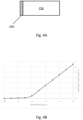
- the effects the response of a detector 25b between the coating 30a in figure 4A and the coating 30b in figure 5A is shown in figure 4B and figure 5B using the same arbitrary units in the figures, respectively.
- the coating 30b is thinner than the coating 30c. Accordingly, the threshold amount of light able to be absorbed by the coating 30b will be lower than the threshold amount of light able to be absorbed by the coating 30c.
- the knee of the response curve is shifted to the right as the coating 30c is able to absorb more photons than the coating 30b. Therefore, it is to be appreciated that the threshold drop density for which the nozzle 17a may be passed or fail may be calibrated by adjusting the thickness of the coating accordingly.
- method 200 may be performed with the apparatus 10a. Indeed, the method 200 may be one way in which apparatus 10a is used and the following discussion of method 200 may lead to a further understanding of the apparatus 10a along with its various components.
- the nozzle 17a-2 ejects drops 50 of print fluid that travel along a drop path toward a receptacle 35a.
- the manner by which the nozzle 17a-2 ejects the drops 50 is not particularly limited.
- the moveable printhead 15a may control the nozzle 17a-2 and eject the drops 50 under pressure such that the drops 50 travel through the air to the receptacle 35a.
- the source of the print fluid provided to the nozzle 17a-2 is also not limited.
- the nozzle 17a-2 may receive print fluid via the moveable printhead 15a from a tank, reservoir, or other print fluid source.
- the moveable printhead 15a may use a thermal ink jet or a piezo ink jet mechanism to push the print fluid through the nozzle 17a-2.
- a motor or pump may be used to pressurize the print fluid.
- the moveable printhead 15a may receive print fluid from multiple sources where each source of print fluid may provide a different print fluid.
- the moveable printhead 15a may have separate tanks of print fluid for different colors, such as cyan, magenta, and yellow. The print fluid from each source may be directed to the nozzle 17a-1, the nozzle 17a-2, and the nozzle 17a-3, respectively.
- the moveable printhead 15a may dispense a mixture of different colors to deposit on the media to generate an output image. Accordingly, each of the nozzle 17a-1, the nozzle 17a-2, and the nozzle 17a-3 may be tested individually to determine their health.
- the light source 20a emits light along an optical path that intersects the drop path of the drops 50 before entering the detector 25a.
- the manner by which the light travels from the light source 20a to the detector 25a is not limited and may involve optical components such as mirrors or prisms to change the direction of the light.
- Block 230 involves absorbing a portion of the light as it travels through the drops 50 from the light source 20a to the detector 25a.
- the manner by which the light is absorbed is not particularly limited.
- the print fluid may be opaque to the light from the light source 20a. Accordingly, as the light passes through the drops 50, the drops will absorb some of the light from the light source 20a.
- the density of the drops 50 is relatively small such that the majority of the light may pass through when the nozzle 17a is healthy and ejecting the upper limit of drops to prove a high drop density. It is to be appreciated that when the nozzle 17a is not healthy, the drop density may be lower and more light from the light source 20a will pass through. Accordingly, the portion of light absorbed will be higher for a healthy nozzle 17a and lower for a nozzle 17a that is unhealthy.
- Block 240 involves absorbing another portion of light using the coating 30a.
- the coating 30a is capable of absorbing light below a threshold amount of light. Accordingly, if the amount of light incident on the coating 30a is below the threshold amount, the coating 30a will absorb substantially all of the remaining light such that substantially no light reaches the photosensitive element of the detector 25a. Therefore, the detector 25a will provide no signal to the controller 100, which indicates a healthy nozzle.
- the coating 30a will absorb a portion of photons incident on the coating 30a up to the threshold amount. The excess photons will then pass through the coating 30a to the photosensitive element of the detector 25a. Therefore, the detector 25a will provide a signal to the controller 100 to indicate that light was detected and that the nozzle 17a is unhealthy.
- the threshold amount of light to be absorbed by the coating 30a may be adjusted to calibrate the coating 30a.
- the thickness of the coating 30a may be varied by applying multiple layers.
- the layers may be added to the coating 30a to absorb more photons.
- the coating 30a may absorb photons having a specific energy within a specific band gap. The band gap is adjusted by applying a voltage across the coating 30a
- the detector 25a is to detect the amount of light incident on a photosensitive element.
- the manner by which the light intensity is measured is not particularly limited.
- the photosensitive element of the detector 25a may include a photodiode or photoresistor.
- the response from the detector is to determine if there is measurable light on the photosensitive element to provide binary response.
- the detector 25a may provide a measurement to the controller 100 instead of a binary pass or fail response.
Landscapes
- General Health & Medical Sciences (AREA)
- General Physics & Mathematics (AREA)
- Life Sciences & Earth Sciences (AREA)
- Chemical & Material Sciences (AREA)
- Analytical Chemistry (AREA)
- Biochemistry (AREA)
- Health & Medical Sciences (AREA)
- Immunology (AREA)
- Physics & Mathematics (AREA)
- Pathology (AREA)
- Coating Apparatus (AREA)
- Engineering & Computer Science (AREA)
- Quality & Reliability (AREA)
- Investigating Or Analysing Materials By Optical Means (AREA)
- Ink Jet (AREA)
Claims (8)
- Vorrichtung (10, 10a), die umfasst:einen Druckkopf (15, 15a), um Tropfen (50) eines Druckfluids auf ein Medium abzugeben, wobei sich die Tropfen entlang eines Tropfenpfads von dem Druckkopf durch die Luft fortbewegen;eine Lichtquelle (20, 20a), um Licht über den Tropfenpfad zu emittieren;einen Detektor (25, 25a), um eine Intensität des Lichts, das von der Lichtquelle aufgenommen wird, zu detektieren, wobei der Tropfenpfad einen optischen Pfad von der Lichtquelle zu dem Detektor kreuzt; undeine Beschichtung (30, 30a, 30b, 30c), die auf dem optischen Pfad zwischen dem Tropfenpfad und dem Detektor platziert ist, wobei die Beschichtung dazu dient, Licht, das eine einfallende Lichtintensität unterhalb einer Schwellenmenge einer Lichtintensität aufweist, zu absorbieren, wobei die Beschichtung dazu dient, das Licht mit einer spezifizierten Energie zu absorbieren, dadurch gekennzeichnet, dass die spezifizierte Energie durch eine Spannung, die über die Beschichtung angelegt wird, abstimmbar ist, wobei die Spannung eine Bandlücke der Beschichtung anpasst.
- Vorrichtung nach Anspruch 1, wobei die Beschichtung direkt an den Detektor angelegt wird.
- Vorrichtung nach Anspruch 1, wobei die Beschichtung eine Dicke über den optischen Pfad aufweist, die gleichmäßig ist.
- Vorrichtung nach Anspruch 3, wobei die Schwellenmenge des Lichts, das durch die Beschichtung zu absorbieren ist, durch die Dicke bestimmt wird.
- Verfahren (200), das umfasst:Ausstoßen (210) von Tropfen (50) eines Druckfluids mittels einer Düse (17a), wobei sich die Tropfen entlang eines Tropfenpfads von der Düse zu einem Behälter (35a) durch die Luft fortbewegen;Emittieren (220) von Licht von einer Lichtquelle (20a) entlang eines optischen Pfads zu einem Detektor (25a), wobei über den optischen Pfad den Tropfenpfad kreuzt;Absorbieren (230) eines ersten Teils des Lichts von der Lichtquelle mit den Tropfen in dem Tropfenpfad;Absorbieren (240) eines zweiten Teils des Lichts von der Lichtquelle mit einer Beschichtung (30, 30a, 30b, 30c), wobei die Beschichtung dazu dient, Licht, das eine einfallende Lichtintensität unterhalb einer Schwellenmenge einer Lichtintensität aufweist, zu absorbieren;Detektieren (250) einer Intensität des Lichts an dem Detektor; undAnpassen der Schwellenmenge an Licht, das durch die Beschichtung zu absorbieren ist, dadurch gekennzeichnet, dass ein Absorbieren des zweiten Teils ein Absorbieren von Photonen mit einer spezifizierten Energie umfasst, wobei die spezifizierte Energie durch eine Spannung, die über die Beschichtung angelegt wird, abstimmbar ist, wobei die Spannung eine Bandlücke der Beschichtung anpasst.
- Verfahren nach Anspruch 5, wobei ein Anpassen der Schwellenmenge ein Variieren einer Dicke der Beschichtung umfasst.
- Vorrichtung nach Anspruch 1, die ferner umfasst:
eine Behälter zum Aufnehmen der Tropfen eines Druckfluids, wobei der Druckkopf ein bewegbarer Druckkopf dazu ist, sich von einer ersten Position oberhalb eines Mediums zu einer zweiten Position oberhalb des Behälters zu bewegen, und eine Düse dazu umfasst, die Tropfen eines Druckfluids mittels des Tropfenpfads in den Behälter abzugeben. - Vorrichtung nach Anspruch 7, wobei die Beschichtung eine gleichmäßige Dicke aufweist und wobei die Schwellenmenge des Lichts, das durch die Beschichtung zu absorbieren ist, von der gleichmäßigen Dicke abhängt.
Applications Claiming Priority (1)
| Application Number | Priority Date | Filing Date | Title |
|---|---|---|---|
| PCT/US2019/036186 WO2020251517A1 (en) | 2019-06-08 | 2019-06-08 | Coatings for optical drop detectors |
Publications (3)
| Publication Number | Publication Date |
|---|---|
| EP3980271A1 EP3980271A1 (de) | 2022-04-13 |
| EP3980271A4 EP3980271A4 (de) | 2022-12-28 |
| EP3980271B1 true EP3980271B1 (de) | 2024-12-25 |
Family
ID=73781532
Family Applications (1)
| Application Number | Title | Priority Date | Filing Date |
|---|---|---|---|
| EP19933088.7A Active EP3980271B1 (de) | 2019-06-08 | 2019-06-08 | Beschichtungen für optische tropfendetektoren |
Country Status (5)
| Country | Link |
|---|---|
| US (1) | US11833815B2 (de) |
| EP (1) | EP3980271B1 (de) |
| JP (1) | JP7196340B2 (de) |
| CN (1) | CN113905892B (de) |
| WO (1) | WO2020251517A1 (de) |
Citations (1)
| Publication number | Priority date | Publication date | Assignee | Title |
|---|---|---|---|---|
| WO2018199879A1 (en) * | 2017-04-24 | 2018-11-01 | Hewlett-Packard Development Company, L.P. | Detecting flying liquid drops |
Family Cites Families (18)
| Publication number | Priority date | Publication date | Assignee | Title |
|---|---|---|---|---|
| US6252237B1 (en) | 1998-07-15 | 2001-06-26 | 3M Innovation Properties Company | Low cost thickness measurement method and apparatus for thin coatings |
| JP2001054954A (ja) | 1999-06-07 | 2001-02-27 | Canon Inc | インクジェットプリント装置および該装置用インクジェットヘッドの吐出状態検出方法 |
| JP2006150637A (ja) | 2004-11-25 | 2006-06-15 | Konica Minolta Medical & Graphic Inc | 液滴検出装置及び液滴検出装置を備えたインクジェット記録装置 |
| JP2007118264A (ja) * | 2005-10-26 | 2007-05-17 | Ricoh Elemex Corp | 液吐出不良検出装置、およびインクジェット記録装置 |
| JP2007296670A (ja) | 2006-04-28 | 2007-11-15 | Canon Inc | 液滴吐出装置、液滴吐出システム、液滴吐出検出方法、及び液滴吐出検出プログラム |
| EP2033791B1 (de) * | 2007-09-04 | 2011-06-15 | Ricoh Company, Ltd. | Flüssigkeitseinspritzkopfeinheit und Bilderzeugungsvorrichtung |
| US8847888B2 (en) * | 2007-12-18 | 2014-09-30 | Microsoft Corporation | Optical mouse with limited wavelength optics |
| JP5073509B2 (ja) * | 2008-01-17 | 2012-11-14 | 株式会社リコー | 画像形成装置、着弾位置ずれ補正方法 |
| US8376506B2 (en) * | 2008-03-25 | 2013-02-19 | Hewlett-Packard Development Company, L.P. | Drop detection |
| US8053782B2 (en) | 2009-08-24 | 2011-11-08 | International Business Machines Corporation | Single and few-layer graphene based photodetecting devices |
| JP2011093155A (ja) | 2009-10-28 | 2011-05-12 | Ricoh Elemex Corp | 液吐出不良検出装置およびインクジェット記録装置 |
| JP2012187274A (ja) | 2011-03-10 | 2012-10-04 | Olympus Medical Systems Corp | 照射プローブおよび観察プローブ |
| US9134233B2 (en) * | 2011-05-31 | 2015-09-15 | Hewlett-Packard Development Company, L.P. | Drop detection assembly and method |
| GB201300695D0 (en) | 2013-01-15 | 2013-02-27 | Univ Exeter The | Graphene deposition enquiry |
| US20170181669A1 (en) | 2014-06-12 | 2017-06-29 | The Trustees Of Columbia University In The City Of New York | Graphene-based nanosensor for identifying target analytes |
| CN105842171B (zh) * | 2015-01-15 | 2019-05-17 | 中国科学院苏州纳米技术与纳米仿生研究所 | 一种生物化学检测系统 |
| EP3233497B1 (de) | 2015-02-27 | 2021-09-15 | Hewlett-Packard Development Company, L.P. | Tropfgeschwindigkeitsabweichungsnachweis |
| CN105226127A (zh) | 2015-10-12 | 2016-01-06 | 南开大学 | 一种基于全内反射结构的石墨烯光电探测器及其制备方法 |
-
2019
- 2019-06-08 EP EP19933088.7A patent/EP3980271B1/de active Active
- 2019-06-08 US US17/416,544 patent/US11833815B2/en active Active
- 2019-06-08 JP JP2021571862A patent/JP7196340B2/ja active Active
- 2019-06-08 WO PCT/US2019/036186 patent/WO2020251517A1/en not_active Ceased
- 2019-06-08 CN CN201980097293.0A patent/CN113905892B/zh active Active
Patent Citations (1)
| Publication number | Priority date | Publication date | Assignee | Title |
|---|---|---|---|---|
| WO2018199879A1 (en) * | 2017-04-24 | 2018-11-01 | Hewlett-Packard Development Company, L.P. | Detecting flying liquid drops |
Also Published As
| Publication number | Publication date |
|---|---|
| US11833815B2 (en) | 2023-12-05 |
| JP2022536074A (ja) | 2022-08-12 |
| US20220097366A1 (en) | 2022-03-31 |
| WO2020251517A1 (en) | 2020-12-17 |
| CN113905892A (zh) | 2022-01-07 |
| JP7196340B2 (ja) | 2022-12-26 |
| CN113905892B (zh) | 2023-05-23 |
| EP3980271A4 (de) | 2022-12-28 |
| EP3980271A1 (de) | 2022-04-13 |
Similar Documents
| Publication | Publication Date | Title |
|---|---|---|
| US9739662B2 (en) | Spectrometry device and image forming apparatus | |
| US6409302B2 (en) | Sensing system for detecting presence of an ink container and level of ink therein | |
| CN104936789B (zh) | 测试打印头的方法和打印机 | |
| EP3067673B1 (de) | Bilderzeugungsvorrichtung und verschmutzungsdetektionsverfahren | |
| US20080136859A1 (en) | Method and apparatus to check piezoelectric inkjet head | |
| JP6471762B2 (ja) | 分光測定装置、画像形成装置、及び分光測定方法 | |
| US5424766A (en) | Ink jet printer control system responsive to acoustical properties of ink | |
| JP2002127387A (ja) | インクジェットプリントヘッドとレシーバとの間の作業間隔の維持方法 | |
| US6626513B2 (en) | Ink detection circuit and sensor for an ink jet printer | |
| EP3980271B1 (de) | Beschichtungen für optische tropfendetektoren | |
| US9033452B2 (en) | Ejection detection device, ejection detection method, and printing apparatus | |
| US8393701B2 (en) | Using light-scattering drop detector to determine turn-on-energy for fluid-ejection nozzle | |
| KR100781997B1 (ko) | 잉크젯 헤드의 캘리브레이션 방법 및 그 장치 | |
| JP4880487B2 (ja) | 液吐出不良検出装置、およびインクジェット記録装置 | |
| KR20090006987A (ko) | 잉크젯 화상형성장치 | |
| US8181953B2 (en) | Member detecting media amount in multiple trays | |
| JP4991508B2 (ja) | インクジェット記録装置、及びその吐出検出用光センサの位置調整方法 | |
| JP4438555B2 (ja) | 液滴の吐出状態検出方法 | |
| US20220088922A1 (en) | Printers and controllers | |
| US11415685B2 (en) | Sensors calibration | |
| JP2014019048A (ja) | 液体消費装置 | |
| US11220118B2 (en) | Media bin sensors | |
| US20210213735A1 (en) | Detecting flying liquid drops | |
| JP2011037201A (ja) | 画像形成装置 | |
| US20200406623A1 (en) | Spitting offsets for printheads |
Legal Events
| Date | Code | Title | Description |
|---|---|---|---|
| STAA | Information on the status of an ep patent application or granted ep patent |
Free format text: STATUS: THE INTERNATIONAL PUBLICATION HAS BEEN MADE |
|
| PUAI | Public reference made under article 153(3) epc to a published international application that has entered the european phase |
Free format text: ORIGINAL CODE: 0009012 |
|
| STAA | Information on the status of an ep patent application or granted ep patent |
Free format text: STATUS: REQUEST FOR EXAMINATION WAS MADE |
|
| 17P | Request for examination filed |
Effective date: 20211112 |
|
| AK | Designated contracting states |
Kind code of ref document: A1 Designated state(s): AL AT BE BG CH CY CZ DE DK EE ES FI FR GB GR HR HU IE IS IT LI LT LU LV MC MK MT NL NO PL PT RO RS SE SI SK SM TR |
|
| DAV | Request for validation of the european patent (deleted) | ||
| DAX | Request for extension of the european patent (deleted) | ||
| A4 | Supplementary search report drawn up and despatched |
Effective date: 20221128 |
|
| RIC1 | Information provided on ipc code assigned before grant |
Ipc: B41J 2/21 20060101ALI20221122BHEP Ipc: G01N 21/85 20060101ALI20221122BHEP Ipc: B41J 29/393 20060101ALI20221122BHEP Ipc: B41J 2/165 20060101AFI20221122BHEP |
|
| STAA | Information on the status of an ep patent application or granted ep patent |
Free format text: STATUS: EXAMINATION IS IN PROGRESS |
|
| 17Q | First examination report despatched |
Effective date: 20240315 |
|
| GRAP | Despatch of communication of intention to grant a patent |
Free format text: ORIGINAL CODE: EPIDOSNIGR1 |
|
| STAA | Information on the status of an ep patent application or granted ep patent |
Free format text: STATUS: GRANT OF PATENT IS INTENDED |
|
| GRAS | Grant fee paid |
Free format text: ORIGINAL CODE: EPIDOSNIGR3 |
|
| INTG | Intention to grant announced |
Effective date: 20241017 |
|
| GRAA | (expected) grant |
Free format text: ORIGINAL CODE: 0009210 |
|
| STAA | Information on the status of an ep patent application or granted ep patent |
Free format text: STATUS: THE PATENT HAS BEEN GRANTED |
|
| AK | Designated contracting states |
Kind code of ref document: B1 Designated state(s): AL AT BE BG CH CY CZ DE DK EE ES FI FR GB GR HR HU IE IS IT LI LT LU LV MC MK MT NL NO PL PT RO RS SE SI SK SM TR |
|
| REG | Reference to a national code |
Ref country code: GB Ref legal event code: FG4D |
|
| REG | Reference to a national code |
Ref country code: CH Ref legal event code: EP |
|
| REG | Reference to a national code |
Ref country code: DE Ref legal event code: R096 Ref document number: 602019064112 Country of ref document: DE |
|
| REG | Reference to a national code |
Ref country code: IE Ref legal event code: FG4D |
|
| REG | Reference to a national code |
Ref country code: LT Ref legal event code: MG9D |
|
| PG25 | Lapsed in a contracting state [announced via postgrant information from national office to epo] |
Ref country code: HR Free format text: LAPSE BECAUSE OF FAILURE TO SUBMIT A TRANSLATION OF THE DESCRIPTION OR TO PAY THE FEE WITHIN THE PRESCRIBED TIME-LIMIT Effective date: 20241225 |
|
| PG25 | Lapsed in a contracting state [announced via postgrant information from national office to epo] |
Ref country code: FI Free format text: LAPSE BECAUSE OF FAILURE TO SUBMIT A TRANSLATION OF THE DESCRIPTION OR TO PAY THE FEE WITHIN THE PRESCRIBED TIME-LIMIT Effective date: 20241225 |
|
| PG25 | Lapsed in a contracting state [announced via postgrant information from national office to epo] |
Ref country code: BG Free format text: LAPSE BECAUSE OF FAILURE TO SUBMIT A TRANSLATION OF THE DESCRIPTION OR TO PAY THE FEE WITHIN THE PRESCRIBED TIME-LIMIT Effective date: 20241225 |
|
| PG25 | Lapsed in a contracting state [announced via postgrant information from national office to epo] |
Ref country code: NO Free format text: LAPSE BECAUSE OF FAILURE TO SUBMIT A TRANSLATION OF THE DESCRIPTION OR TO PAY THE FEE WITHIN THE PRESCRIBED TIME-LIMIT Effective date: 20250325 |
|
| PG25 | Lapsed in a contracting state [announced via postgrant information from national office to epo] |
Ref country code: LV Free format text: LAPSE BECAUSE OF FAILURE TO SUBMIT A TRANSLATION OF THE DESCRIPTION OR TO PAY THE FEE WITHIN THE PRESCRIBED TIME-LIMIT Effective date: 20241225 Ref country code: GR Free format text: LAPSE BECAUSE OF FAILURE TO SUBMIT A TRANSLATION OF THE DESCRIPTION OR TO PAY THE FEE WITHIN THE PRESCRIBED TIME-LIMIT Effective date: 20250326 |
|
| PG25 | Lapsed in a contracting state [announced via postgrant information from national office to epo] |
Ref country code: RS Free format text: LAPSE BECAUSE OF FAILURE TO SUBMIT A TRANSLATION OF THE DESCRIPTION OR TO PAY THE FEE WITHIN THE PRESCRIBED TIME-LIMIT Effective date: 20250325 |
|
| REG | Reference to a national code |
Ref country code: NL Ref legal event code: MP Effective date: 20241225 |
|
| PG25 | Lapsed in a contracting state [announced via postgrant information from national office to epo] |
Ref country code: NL Free format text: LAPSE BECAUSE OF FAILURE TO SUBMIT A TRANSLATION OF THE DESCRIPTION OR TO PAY THE FEE WITHIN THE PRESCRIBED TIME-LIMIT Effective date: 20241225 |
|
| REG | Reference to a national code |
Ref country code: AT Ref legal event code: MK05 Ref document number: 1753858 Country of ref document: AT Kind code of ref document: T Effective date: 20241225 |
|
| PG25 | Lapsed in a contracting state [announced via postgrant information from national office to epo] |
Ref country code: SM Free format text: LAPSE BECAUSE OF FAILURE TO SUBMIT A TRANSLATION OF THE DESCRIPTION OR TO PAY THE FEE WITHIN THE PRESCRIBED TIME-LIMIT Effective date: 20241225 |
|
| PG25 | Lapsed in a contracting state [announced via postgrant information from national office to epo] |
Ref country code: PL Free format text: LAPSE BECAUSE OF FAILURE TO SUBMIT A TRANSLATION OF THE DESCRIPTION OR TO PAY THE FEE WITHIN THE PRESCRIBED TIME-LIMIT Effective date: 20241225 |
|
| PGFP | Annual fee paid to national office [announced via postgrant information from national office to epo] |
Ref country code: DE Payment date: 20250520 Year of fee payment: 7 |
|
| PG25 | Lapsed in a contracting state [announced via postgrant information from national office to epo] |
Ref country code: ES Free format text: LAPSE BECAUSE OF FAILURE TO SUBMIT A TRANSLATION OF THE DESCRIPTION OR TO PAY THE FEE WITHIN THE PRESCRIBED TIME-LIMIT Effective date: 20241225 |
|
| PG25 | Lapsed in a contracting state [announced via postgrant information from national office to epo] |
Ref country code: IS Free format text: LAPSE BECAUSE OF FAILURE TO SUBMIT A TRANSLATION OF THE DESCRIPTION OR TO PAY THE FEE WITHIN THE PRESCRIBED TIME-LIMIT Effective date: 20250425 |
|
| PG25 | Lapsed in a contracting state [announced via postgrant information from national office to epo] |
Ref country code: PT Free format text: LAPSE BECAUSE OF FAILURE TO SUBMIT A TRANSLATION OF THE DESCRIPTION OR TO PAY THE FEE WITHIN THE PRESCRIBED TIME-LIMIT Effective date: 20250428 |
|
| PG25 | Lapsed in a contracting state [announced via postgrant information from national office to epo] |
Ref country code: EE Free format text: LAPSE BECAUSE OF FAILURE TO SUBMIT A TRANSLATION OF THE DESCRIPTION OR TO PAY THE FEE WITHIN THE PRESCRIBED TIME-LIMIT Effective date: 20241225 |
|
| PG25 | Lapsed in a contracting state [announced via postgrant information from national office to epo] |
Ref country code: RO Free format text: LAPSE BECAUSE OF FAILURE TO SUBMIT A TRANSLATION OF THE DESCRIPTION OR TO PAY THE FEE WITHIN THE PRESCRIBED TIME-LIMIT Effective date: 20241225 Ref country code: AT Free format text: LAPSE BECAUSE OF FAILURE TO SUBMIT A TRANSLATION OF THE DESCRIPTION OR TO PAY THE FEE WITHIN THE PRESCRIBED TIME-LIMIT Effective date: 20241225 |
|
| PG25 | Lapsed in a contracting state [announced via postgrant information from national office to epo] |
Ref country code: SK Free format text: LAPSE BECAUSE OF FAILURE TO SUBMIT A TRANSLATION OF THE DESCRIPTION OR TO PAY THE FEE WITHIN THE PRESCRIBED TIME-LIMIT Effective date: 20241225 |
|
| PG25 | Lapsed in a contracting state [announced via postgrant information from national office to epo] |
Ref country code: CZ Free format text: LAPSE BECAUSE OF FAILURE TO SUBMIT A TRANSLATION OF THE DESCRIPTION OR TO PAY THE FEE WITHIN THE PRESCRIBED TIME-LIMIT Effective date: 20241225 |
|
| PG25 | Lapsed in a contracting state [announced via postgrant information from national office to epo] |
Ref country code: IT Free format text: LAPSE BECAUSE OF FAILURE TO SUBMIT A TRANSLATION OF THE DESCRIPTION OR TO PAY THE FEE WITHIN THE PRESCRIBED TIME-LIMIT Effective date: 20241225 |
|
| PG25 | Lapsed in a contracting state [announced via postgrant information from national office to epo] |
Ref country code: SE Free format text: LAPSE BECAUSE OF FAILURE TO SUBMIT A TRANSLATION OF THE DESCRIPTION OR TO PAY THE FEE WITHIN THE PRESCRIBED TIME-LIMIT Effective date: 20241225 |
|
| REG | Reference to a national code |
Ref country code: DE Ref legal event code: R097 Ref document number: 602019064112 Country of ref document: DE |
|
| PG25 | Lapsed in a contracting state [announced via postgrant information from national office to epo] |
Ref country code: DK Free format text: LAPSE BECAUSE OF FAILURE TO SUBMIT A TRANSLATION OF THE DESCRIPTION OR TO PAY THE FEE WITHIN THE PRESCRIBED TIME-LIMIT Effective date: 20241225 |
|
| PLBE | No opposition filed within time limit |
Free format text: ORIGINAL CODE: 0009261 |
|
| STAA | Information on the status of an ep patent application or granted ep patent |
Free format text: STATUS: NO OPPOSITION FILED WITHIN TIME LIMIT |
|
| REG | Reference to a national code |
Ref country code: CH Ref legal event code: L10 Free format text: ST27 STATUS EVENT CODE: U-0-0-L10-L00 (AS PROVIDED BY THE NATIONAL OFFICE) Effective date: 20251105 |
|
| 26N | No opposition filed |
Effective date: 20250926 |
|
| REG | Reference to a national code |
Ref country code: CH Ref legal event code: H13 Free format text: ST27 STATUS EVENT CODE: U-0-0-H10-H13 (AS PROVIDED BY THE NATIONAL OFFICE) Effective date: 20260127 |
|
| PG25 | Lapsed in a contracting state [announced via postgrant information from national office to epo] |
Ref country code: MC Free format text: LAPSE BECAUSE OF FAILURE TO SUBMIT A TRANSLATION OF THE DESCRIPTION OR TO PAY THE FEE WITHIN THE PRESCRIBED TIME-LIMIT Effective date: 20241225 |