EP3979293B1 - Aufnahmeeinheit für sicherungslasttrennschalter - Google Patents
Aufnahmeeinheit für sicherungslasttrennschalter Download PDFInfo
- Publication number
- EP3979293B1 EP3979293B1 EP21200211.7A EP21200211A EP3979293B1 EP 3979293 B1 EP3979293 B1 EP 3979293B1 EP 21200211 A EP21200211 A EP 21200211A EP 3979293 B1 EP3979293 B1 EP 3979293B1
- Authority
- EP
- European Patent Office
- Prior art keywords
- clamping
- holding
- contact
- clamping jaws
- section
- Prior art date
- Legal status (The legal status is an assumption and is not a legal conclusion. Google has not performed a legal analysis and makes no representation as to the accuracy of the status listed.)
- Active
Links
Images




Classifications
-
- H—ELECTRICITY
- H01—ELECTRIC ELEMENTS
- H01H—ELECTRIC SWITCHES; RELAYS; SELECTORS; EMERGENCY PROTECTIVE DEVICES
- H01H85/00—Protective devices in which the current flows through a part of fusible material and this current is interrupted by displacement of the fusible material when this current becomes excessive
- H01H85/02—Details
- H01H85/20—Bases for supporting the fuse; Separate parts thereof
- H01H85/203—Bases for supporting the fuse; Separate parts thereof for fuses with blade type terminals
- H01H85/204—Bases for supporting the fuse; Separate parts thereof for fuses with blade type terminals for low voltage fuses with knife-blade end contacts
-
- H—ELECTRICITY
- H01—ELECTRIC ELEMENTS
- H01R—ELECTRICALLY-CONDUCTIVE CONNECTIONS; STRUCTURAL ASSOCIATIONS OF A PLURALITY OF MUTUALLY-INSULATED ELECTRICAL CONNECTING ELEMENTS; COUPLING DEVICES; CURRENT COLLECTORS
- H01R13/00—Details of coupling devices of the kinds covered by groups H01R12/70 or H01R24/00 - H01R33/00
- H01R13/02—Contact members
- H01R13/10—Sockets for co-operation with pins or blades
- H01R13/11—Resilient sockets
- H01R13/112—Resilient sockets forked sockets having two legs
-
- H—ELECTRICITY
- H01—ELECTRIC ELEMENTS
- H01R—ELECTRICALLY-CONDUCTIVE CONNECTIONS; STRUCTURAL ASSOCIATIONS OF A PLURALITY OF MUTUALLY-INSULATED ELECTRICAL CONNECTING ELEMENTS; COUPLING DEVICES; CURRENT COLLECTORS
- H01R13/00—Details of coupling devices of the kinds covered by groups H01R12/70 or H01R24/00 - H01R33/00
- H01R13/02—Contact members
- H01R13/10—Sockets for co-operation with pins or blades
- H01R13/11—Resilient sockets
- H01R13/113—Resilient sockets co-operating with pins or blades having a rectangular transverse section
-
- H—ELECTRICITY
- H01—ELECTRIC ELEMENTS
- H01R—ELECTRICALLY-CONDUCTIVE CONNECTIONS; STRUCTURAL ASSOCIATIONS OF A PLURALITY OF MUTUALLY-INSULATED ELECTRICAL CONNECTING ELEMENTS; COUPLING DEVICES; CURRENT COLLECTORS
- H01R13/00—Details of coupling devices of the kinds covered by groups H01R12/70 or H01R24/00 - H01R33/00
- H01R13/02—Contact members
- H01R13/15—Pins, blades or sockets having separate spring member for producing or increasing contact pressure
- H01R13/18—Pins, blades or sockets having separate spring member for producing or increasing contact pressure with the spring member surrounding the socket
-
- H—ELECTRICITY
- H01—ELECTRIC ELEMENTS
- H01R—ELECTRICALLY-CONDUCTIVE CONNECTIONS; STRUCTURAL ASSOCIATIONS OF A PLURALITY OF MUTUALLY-INSULATED ELECTRICAL CONNECTING ELEMENTS; COUPLING DEVICES; CURRENT COLLECTORS
- H01R13/00—Details of coupling devices of the kinds covered by groups H01R12/70 or H01R24/00 - H01R33/00
- H01R13/02—Contact members
- H01R13/15—Pins, blades or sockets having separate spring member for producing or increasing contact pressure
- H01R13/187—Pins, blades or sockets having separate spring member for producing or increasing contact pressure with spring member in the socket
-
- H—ELECTRICITY
- H01—ELECTRIC ELEMENTS
- H01R—ELECTRICALLY-CONDUCTIVE CONNECTIONS; STRUCTURAL ASSOCIATIONS OF A PLURALITY OF MUTUALLY-INSULATED ELECTRICAL CONNECTING ELEMENTS; COUPLING DEVICES; CURRENT COLLECTORS
- H01R25/00—Coupling parts adapted for simultaneous co-operation with two or more identical counterparts, e.g. for distributing energy to two or more circuits
- H01R25/14—Rails or bus-bars constructed so that the counterparts can be connected thereto at any point along their length
- H01R25/142—Their counterparts
Definitions
- the present invention relates to a receiving unit for a first contact element of an electrical device, in particular a fuse link of a fuse switch disconnector.
- a similar receiving unit however designed to accommodate a contact pin for a meter connection block for connecting an electricity meter, is available from DE 10 2018 117 723 B4 known.
- a contact base for NH fuse cartridges which comprises a receiving unit with a holder element to which two clamping jaws are attached, between which a contact element can be clamped.
- the device also comprises a helical compression spring, which is arranged between two pressure arms.
- the DE 1 741 702 U discloses a device for receiving a contact element which can be contacted by two clamping jaws, each of the clamping jaws having an associated spring.
- a device which comprises a receiving unit with two holder elements, wherein a helical compression spring is provided between two ends of these holder elements.
- a rail clamp for clamping and electrical contacting which comprises two contact pieces which can be linearly displaced against each other, wherein a spring element which generates a contact force is arranged between these two contact pieces.
- the DE 1 059 068 B describes a one- or multi-part lyre contact element, in particular for safety parts, which has spoon-shaped contact jaws.
- a receiving unit for a first contact element of an electrical device in particular a fuse insert of a fuse switch disconnector, comprises a holder element and one or more first clamping units.
- the one or more first clamping units can each receive a first contact element.
- Each first clamping unit comprises two separate clamping jaws, between which the first contact element can be clamped, and a first spring element which is formed in one piece, wherein the two clamping jaws are fastened to the holding element by means of the first spring element.
- the first spring element is designed such that it at least partially encompasses the two clamping jaws and prestresses them towards one another, and the two clamping jaws are designed such that they define a receiving area for the first contact element.
- the receiving unit additionally comprises a second clamping unit.
- This second clamping unit comprises a clamping element and a second spring element, wherein the clamping element is arranged to be movable relative to the holding element.
- the holding element and the clamping element are designed such that they define a receiving area for the second contact element, and the second spring element is designed such that it biases the holding element and the clamping element towards one another for contacting a second contact element inserted into the receiving area.
- a mounting unit for a fuse switch disconnector can be provided multiple times in a fuse switch disconnector.
- a fuse switch disconnector can comprise a total of six such mounting units.
- a receiving unit according to the invention has the particular advantage that individual functional elements of the receiving unit, which are not manufactured in one piece, can easily be manufactured from different materials, so that the materials and also the geometry of the individual units can be better adapted to their desired, specific functions, so that, in contrast to one-piece receiving units or receiving units with fewer units, better performance data can be made possible.
- the material for the clamping jaws and the holding element can be selected with regard to its main functionalities, namely conductivity and stability, while the flexibility required for a clamping effect to securely fasten the first contact element can be realized by the first spring element, whereby no special conductivity requirements need to be placed on the first spring element.
- the material for the holding element and the clamping element can be selected with regard to its main functions, namely conductivity and stability, while the required flexibility required for a clamping effect to securely fasten the second contact element can be realized by the second spring element, whereby no special conductivity requirements need to be placed on the second spring element.
- the inventive design of the first clamping unit with two separate clamping jaws in particular in conjunction with the special fastening of the clamping jaws to the holding element by means of the first spring element, has the effect that the separate clamping jaws do not have to be bent over wide areas for inserting or removing a first contact element, as is the case with one-piece clamping units, but rather move, to a certain extent, independently of one another during operation and, similar to a hinge, can open or close relative to one another, for example by a slight, relative rotational movement to one another and/or can also move relative to other elements of the receiving unit, in particular relative to the holding element.
- the inventive design of the preferably additionally provided second clamping unit with the clamping element, the holding element and the second spring element has the advantage that the clamping element does not have to be bent over large areas, as is the case with one-piece clamping units, but the clamping effect is achieved by the relative movement of the clamping element relative to the holding element in conjunction with the spring effect of the second spring element.
- clamping jaws in the sense of this invention are to be understood in particular as clamping jaws which are individual elements, i.e. not as a one-piece clamping unit in which, for example, by bending a one-piece element two opposing clamping jaws are formed.
- the individual or separate clamping jaws are also not formed into an essentially one-piece element by soldering or welding or any other material connection.
- the positioning of the separate clamping jaws is ensured only by the shape of the separate clamping jaws themselves and by the shape of other associated elements and by spring elements.
- the force required to insert the preferably provided second contact element between the holding element and the clamping element is lower than in the case of one-piece receiving units, while on the other hand the second spring element ensures a secure fastening of the second contact element in the second clamping unit.
- Another very significant advantage of the receiving unit according to the present invention is the cost-effective production made possible by the structure. All parts of the receiving unit can be manufactured individually and then assembled, and it is not necessary to bend or adjust individual parts in an assembled state.
- the fact that the clamping jaws are designed as separate clamping jaws means that the individual clamping jaws can be manufactured in a simple manner, for example by forming a strip and then cutting the strip, which results in great cost savings.
- the receiving unit according to the invention therefore not only leads to a more reliable function and a longer service life, but also to simpler and safer operation, in which less force has to be used, especially when the first or the second contact element is used, but also leads to a noticeable reduction in costs during production and thus the costs of the elements, both the receiving unit and the entire fuse switch disconnector, which, as mentioned above, comprises several receiving units.
- the present receiving unit in particular the first clamping unit, has the advantage that only a single, one-piece first spring element is required to attach the two clamping jaws to the holding element and simultaneously pre-tension them towards each other.
- DE 10 2018 117 723 B4 two spring elements are described, one of which serves to attach the clamping jaws to the holding element and the other serves to pre-tension the clamping jaws towards each other. Because only a single spring element has to be produced for the first clamping unit, which performs the functions of the two in DE 10 2018 117 723 B4 described spring elements, the costs for manufacturing the receiving unit and the entire fuse switch disconnector can be further reduced. In addition, fewer steps are required to assemble the receiving unit, since only a single first spring element needs to be suitably attached to provide the first clamping unit; this also simplifies the assembly of the receiving unit.
- the two separate clamping jaws of the first clamping unit are designed so that they have an identical shape. This has a further advantage in particular during production, since only one type of clamping jaw has to be produced, as described above, for example by forming a strip which can subsequently be cut. The reduction in the number of different parts automatically ensures a noticeable reduction in the overall costs, and it also enables individual parts to be replaced with less effort.
- the two clamping jaws are arranged on the holding element in such a way that they are arranged in a mirror image of each other. This is particularly advantageous if the two clamping jaws are designed identically, as already described above. In particular, this further simplifies the assembly of the receiving unit, since the two clamping jaws can be mounted on the holding element in an identical manner, just in a mirror image arrangement.
- the first spring element at least partially surrounds the holding element. This supports easy handling and assembly because the two clamping jaws and the first spring element can simply be pushed onto the holding element. In particular, it is possible to first place the two clamping jaws onto the holding element and then use the first spring element to clamping jaws to the holding element; alternatively, the two clamping jaws can first be secured to one another by means of the first spring element and then the unit thus created of the two clamping jaws and the first spring element can be placed together on the holding element.
- the first spring element is plate-shaped, partially plate-shaped or essentially plate-shaped, which has the advantage that the first spring element is particularly stable and can be manufactured inexpensively.
- plate-shaped does not necessarily mean flat, but different sections of the spring element can be curved to different degrees.
- the first spring element is only curved in one direction, so that the Gaussian curvature of the surface of the first spring element is zero.
- each of the two clamping jaws comprises a foot section which is designed and shaped such that, in the assembled state, it rests at least partially against the holding element, preferably over a large area. This in particular creates reliable contact between the two clamping jaws and the holding element.
- the holding element has two lateral recesses into which the foot sections of the two clamping jaws are inserted. In this way, the clamping jaws can be inserted and positioned easily and quickly during assembly.
- each of the two clamping jaws comprises a leg portion which adjoins the foot portion of the respective clamping jaw, and the first spring element exerts a force on the two leg portions in each case, so that the two clamping jaws are held on the holding element.
- each of the two leg sections has a notch or recess
- the first spring element comprises two end sections, each of which engages in a corresponding one of the two notches or recesses, so that a point of application of the force of the first spring element on the respective leg section lies within or on the edge of the notch or recess.
- the notches or recesses can each have a concave surface and the end sections of the first spring element can each have a corresponding convex surface, so that the end sections lie flat against the respective notches.
- each of the two clamping jaws comprises a contact section which adjoins the leg section, wherein the contact sections of the two clamping jaws are in contact with one another when no contact element is clamped between the two clamping jaws.
- the two clamping jaws can be in contact with one another, for example, at a common contact point or via a common contact surface.
- each of the two clamping jaws has a receiving section which adjoins the respective contact section.
- the two receiving sections are designed such that they define the receiving area for the first contact element. When the contact element is clamped between the two clamping jaws, it is therefore located between the two receiving sections. In other words, the first contact element can be clamped between the two receiving sections.
- the different sections can each be shaped and dimensioned in such a way that they optimally fulfil their respective functions.
- the receiving sections can be shaped and dimensioned in such a way that the first contact element can be clamped particularly securely between them without having to pay special attention to the fastening mechanism of the clamping jaws on the holding element. This allows a particularly secure fastening of the first contact element to be achieved.
- each of the two receiving sections comprises an opening section, wherein the opening sections of the two clamping jaws extend in opposite directions relative to a central axis between the two clamping jaws, so that the two opening sections form an opening region for inserting the first contact element.
- each of the two receiving sections can comprise a connecting section that adjoins the respective contact section and the opening section that adjoins the connecting section.
- the two opening sections can be inclined in opposite directions with respect to the respective connecting sections, and within the receiving region for the first contact element, the distance between the two connection points between the respective connecting sections and opening sections of the two clamping jaws can be a minimum distance between the two clamping jaws.
- the two opening sections allow the first contact element to be inserted between the two clamping jaws, thus preventing damage to the receiving unit when inserting the first contact element.
- a first distance is defined as a distance between a first point and a second point
- a second distance is defined as a distance between the second point and a third point.
- the first point is defined as a point within the contact section, preferably a center point of the contact section, of one of the two clamping jaws.
- the second point is defined as a point of application of the force of the first spring element on the leg section of the respective clamping jaw or a point within or on the edge of the notch of the respective leg section, particularly preferably a center point of the notch of the respective leg section.
- the third point is defined as a point of contact between the foot section of the respective clamping jaw and the holding element.
- the third point touches a surface of the holding element that faces away from the receiving area for the first contact element, or the third point is at the maximum distance from the second point among all points of contact between the foot section of the respective clamping jaw and the holding element.
- the second distance is greater than the first distance, preferably at least twice or three times as large as the first distance.
- the advantage of this embodiment is that when no contact element is clamped between the clamping jaws and the first spring element exerts a force on the second point of the two clamping jaws, the first point and the third point each form a counterforce for the force of the first spring element.
- the first distance then corresponds to a first force lever and the second distance to a second force lever. Because the second force lever is larger than the first force lever, the spreading force of the clamping jaws at the third point is reduced. This makes it easier to place the clamping jaws with the foot sections on the holding element, especially when several clamping jaws are placed one behind the other. This simplifies the assembly of the receiving unit.
- a third distance is further defined as a distance between a fourth point and the second point.
- the fourth point is defined as a Contact point between a clamping jaw and the first contact element when the first contact element is clamped between the two clamping jaws, or as a connection point between the connection section and the opening section of the clamping jaw, or as a point within the receiving section of the clamping jaw at which the distance between the two clamping jaws within the receiving area for the first contact element is minimal.
- the third distance is greater than the second distance.
- This preferred embodiment has the advantage that when a first contact element is clamped between the clamping jaws and the first spring element exerts a force on the second point of the two clamping jaws, the fourth point and the third point each form a counterforce for the force of the first spring element.
- the third distance then corresponds to a third force lever and the second distance to a second force lever. Since the third lever is larger than the second lever, the spreading force at the third point is increased in this case. This means that the foot sections of the clamping jaws are pressed more firmly against the holding element, and this increases the stability of the attachment between the clamping jaws and the holding element.
- the two clamping jaws and the holding element are made of a first material that is electrically conductive, while the first spring element is made of a second material, preferably spring steel, wherein the second material differs from the first material.
- the two clamping jaws and the holding element are made of solid electrolytic copper with high electrical conductivity (e.g. 50 to 60 Siemens, in particular e.g. 58 Siemens).
- the clamping jaws and the holding element are galvanically silver-plated in order to ensure good contact and low power losses.
- the holding element and the two clamping jaws are connected to one another and held in their positions relative to one another exclusively by their geometric shape and the first spring element.
- the receiving unit is designed such that the clamping jaws can be repeatedly removed from the holding element of the receiving unit and repositioned and/or refastened. This is also made possible by the structure of the receiving unit described in claim 1, whereby no welding or soldering between these elements is required.
- the two clamping jaws can be pulled off the holding element of the receiving unit after or by releasing and removing the first spring element, in particular in a linear direction, whereby it is also possible for the two clamping jaws to be pulled off together with the first spring element before releasing and removing the first spring element.
- the holding element comprises a first holding section, a connecting holding section which adjoins the first holding section, and a second holding section which adjoins the connecting holding section.
- the first holding section and the second holding section are plate-shaped or disc-shaped, and preferably the first holding section and the second holding section are arranged parallel to one another.
- the two clamping jaws of the first clamping unit can be attached to the first holding section, while the clamping element of the second clamping unit can be attached to the second holding section.
- This allows the relative arrangement of the first clamping unit and the second clamping unit to be optimally adapted to the respective application, for example to the arrangement of a first and a second contact element of a fuse switch disconnector system, which are connected to one another by the receiving unit.
- the plate-shaped or disc-shaped design of the two holding sections also enables a stable attachment of the two clamping units to the respective holding sections, as well as a cost-effective production of the holding element.
- the entire holding element can first be manufactured in a plate-shaped or disc-shaped manner, and then the first and second holding portions may be formed by bending the two end portions of the holding member relative to the connecting holding portion.
- the clamping element comprises a first clamping section, a connecting clamping section which adjoins the first clamping section, and a second clamping section which adjoins the connecting clamping section.
- the first clamping section and the second clamping section are plate-shaped or disc-shaped, and preferably the first clamping section and the second clamping section are arranged parallel to one another.
- the first clamping section can be used to fasten the clamping element to the holding element, while the second clamping section can be used to fasten the second contact element, so that each section can be optimally adapted to its function.
- the plate-shaped or disc-shaped design of the two clamping sections also enables the various parts to be fastened to one another in a particularly stable manner, as well as cost-effective production of the clamping element.
- the entire clamping element can first be manufactured in a plate-shaped or disc-shaped manner, and then the first and second clamping sections can be formed by bending the two end sections of the clamping element relative to the connecting clamping section.
- the second holding section of the holding element and the first clamping section of the clamping element are arranged parallel to one another.
- the second holding section and the first clamping section can form a receiving area for the second contact element, which is delimited by two parallel surfaces and is therefore optimized for receiving a second contact element with two parallel side surfaces, such as a cuboid or substantially cuboid busbar.
- the clamping element is arranged to be movable relative to the holding element and is preferably arranged to be linearly movable along a clamping direction, wherein the clamping direction is particularly preferably perpendicular to the second holding section and/or the first clamping section.
- connection holding section can have a first opening and the first clamping section can have a first projection which engages in the first opening and is arranged to be movable within the first opening along the clamping direction, so that the clamping element is arranged to be movable relative to the holding element along the clamping direction.
- the connecting clamping section can have a second opening and the second holding section can have a second projection which engages in the second opening and is arranged to be movable within the second opening along the clamping direction, so that the clamping element is arranged to be movable relative to the holding element along the clamping direction.
- the receiving unit can comprise a joint element which connects the clamping element and the holding element to one another, so that the clamping element is arranged to be rotatable about a rotation axis relative to the holding element, wherein the rotation axis is preferably arranged parallel to the second holding section and/or the first clamping section.
- the joint element can connect the connecting holding section and the first clamping section to one another, or connect the second holding section and the connecting clamping section to one another.
- the holding element and the clamping element are connected to one another and held in their positions relative to one another exclusively by their geometric shape and the second spring element.
- the receiving unit comprises two or three first clamping units, each clamping unit serving to receive a respective first contact element.
- a fuse switch disconnector designed for one or more, preferably three, fuse links comprises: for each fuse link, one, preferably two receiving units as described above for clamping one contact element, preferably a contact blade, of the respective fuse link.
- a further fuse switch disconnector for an N-pole Busbar system with N busbars where N is a natural number, preferably N is equal to three: at least N receiving units as described above for contacting each of the N busbars.
- Fig. 1 shows an embodiment of a fuse switch disconnector 1 according to the invention
- This fuse switch disconnector 1 is a 3-pole NH fuse switch disconnector 1 that is designed for a total of three fuse inserts.
- the fuse switch disconnector 1 comprises a base element 10 and a cover element 20 into which the three fuse inserts can be inserted.
- the fuse switch disconnector 1 also comprises two receiving units 6 according to the invention for each of the three fuse inserts for clamping and contacting a contact blade 90 of the respective fuse insert, i.e. a total of six receiving units 6 according to the invention.
- the fuse switch disconnector 1 is also designed such that it can be attached to a busbar system that, in the 3-pole version, comprises a total of three busbars 80, each busbar 80 being clamped into and contacting one of the receiving units 6.
- Each of the six receiving units 6 thus has an identical first clamping unit, the six first clamping units each being able to accommodate a contact blade 90 of one of the three fuse inserts.
- three of the six receiving units have a second clamping unit for contacting one of the three busbars, while the remaining three receiving units 6 are connected to the input and output connections of the fuse switch disconnector 1.
- three of the six receiving units 6 are identically designed, each with a first and a second clamping unit, and each connect a contact blade 90 of a fuse insert to a corresponding busbar 80.
- FIGS. 2A to 3B show from different perspectives an embodiment of a receiving unit 6 according to the invention, which comprises a holding element 60, a first clamping unit and a second clamping unit.
- the first clamping unit contains two separate clamping jaws 610 and a first spring element 620 and serves to receive a first contact element 90, preferably a contact blade 90 of a fuse insert of the fuse switch disconnector 1.
- the second clamping unit contains a clamping element 630 and a second spring element 640 and serves to receive a second contact element 80, preferably a busbar 80.
- the first and the second clamping unit are each attached to the holding element 60.
- FIGS. 2A to 3B each show a state of the receiving unit in which neither a first contact element 90 nor a second contact element 80 is clamped.
- the holding element 60 and then the first clamping unit are described in more detail.
- the second clamping unit is described later in connection with Fig. 5 described in more detail.
- the holding element 60 includes a first holding portion 61, a connecting holding portion 62 which adjoins the first holding portion 61, and a second Holding section 63 which adjoins the connection holding section 62.
- the first holding section 61, the connection holding section 62 and the second holding section 63 are each plate-shaped. Both the first holding section 61 and the second holding section 62 run perpendicular to the connection holding section 62, so that in particular the first holding section 61 and the second holding section 63 run parallel to one another.
- first holding section 61 and the second holding section 63 each extend in the same direction starting from the connection holding section 62, but the first holding section 61 and the second holding section 63 can also extend in opposite directions, for example, depending on the positions at which the first and second contact elements are to be arranged relative to one another.
- the two clamping jaws 610 of the first clamping unit are fastened to the first holding section 61, while the clamping element 630 of the second clamping unit is fastened to the second holding section 63.
- the holding element is made of an electrically conductive material, for example solid electrolytic copper with high electrical conductivity (e.g. 50 or 60 Siemens, in particular e.g. 58 Siemens).
- the holding element is also electroplated with silver to ensure good contact and low power losses.
- the two clamping jaws 610 of the first clamping unit are each inserted with a foot section 613 into a lateral recess 611 or 612 of the first holding section 61.
- the clamping jaws 610 also have an identical shape, which will be described later in connection with Fig. 3B described in more detail, and are attached to the first holding section 61 such that they are arranged in mirror image to one another. A receiving area for the first contact element 90 is thus formed between the two clamping jaws 610.
- the two clamping jaws 610 can also be made of the same material as the holding element 60.
- the first spring element 620 is formed in one piece and in the shape of a plate and is curved in only one direction, so that the Gaussian curvature is zero on the entire curved surface of the second spring element.
- the first spring element 620 surrounds the first holding section 61 of the holding element 60 and the two clamping jaws 610 and clamps the two clamping jaws 610 towards each other.
- the first spring element 620 exerts a force on the two clamping jaws 610 so that the two clamping jaws are held on the holding element 60.
- the two end sections 621 and 622 of the first spring element 620 each engage in a notch 617 in the two clamping jaws 610 so that a point of application of the force of the first spring element 620 on the two clamping jaws 620 is inside or on the edge of the notch 617.
- the material of the first spring element 620 may differ from the material of the holding element 60 and the two clamping jaws 610 and may, for example, be spring steel.
- FIG. 3B the different sections of the clamping jaws 610 are shown.
- Each of the two clamping jaws comprises a foot section 613, a leg section 614, a contact section 615 and a receiving section 616, these sections adjoining one another in the order mentioned.
- each clamping jaw 610 is designed such that it encompasses the first holding portion 61 of the holding element 60 and at least partially rests against the first holding portion 61, so that contact is established between the respective clamping jaw 610 and the holding element 60.
- Each of the two foot portions 613 is inserted into one of two opposite lateral recesses 611 and 612 of the first holding portion 61.
- the foot portion 613 of each clamping jaw 610 touches the first holding portion 61 along a first edge, which in the front view of Fig. 3B corresponds to the contact point P3.
- the first edge delimits a first surface of the first holding section 61, which faces away from the receiving area for the first contact element 90.
- each foot section 613 also touches the first holding section 61 along a second edge which delimits a second surface of the first holding section 61, the second surface facing the receiving area for the first contact element 90.
- the first and second surfaces are opposite surfaces of the plate-shaped first holding section 61. It should be noted, however, that the foot sections 613 of the two clamping jaws 610 do not necessarily have to touch the first holding section 61 only along one or more edges, but can also lie flat against the first holding section.
- the leg sections 614 are connected to the foot sections 613 of the two clamping jaws 610.
- the leg sections 614 of the two clamping jaws 610 run parallel or essentially parallel to one another at a predetermined distance.
- Each leg section 614 has a concavely shaped notch into which an end section 621 or 622 of the first spring element 620 engages.
- the end section 621 or 622 of the first spring element 620 touches the respective notch 617 on two edges, one of which corresponds to the one shown in the front view of Fig. 3B corresponds to the point P2 shown, which is thus a point of application of the force of the first spring element 620 on the leg section 614 of the respective clamping jaw 610.
- the end sections 621 and 622 of the first spring element can also touch the respective notches 617 flatly.
- the contact sections 615 are connected to the leg sections 614 of the two clamping jaws 610.
- the contact sections 615 of the two clamping jaws 610 touch each other and in this embodiment are in contact via a common contact surface, provided that no first contact element 90 is clamped between the two clamping jaws 610.
- a center point of the two contact sections 615 is in Fig. 3B each designated P1.
- the first spring element 620 exerts a force with its end sections 621 and 622 on the leg sections 614 of the two clamping jaws 610, in particular on the respective points of application P2.
- the contact sections 615 of the two clamping jaws 610, in particular the center point P1, and the contact points P3 of the clamping jaws 610 with the first holding section 61 each form abutments for the force of the first spring element 620.
- the distance L1 between the points P1 and P2 is smaller than the distance L2 between the points P2 and P3.
- the distances L1 and L2 each correspond to a lever of the force of the first spring element 620 on the two clamping jaws 610.
- the force lever L2 is larger than the force lever L1
- the spreading force of the clamping jaws 610 at point P3, i.e. the force effect of the foot sections 613 on the first holding element 60 at point P3, is reduced. This allows the clamping jaws 610 to be easily plugged onto the holding element 60, especially when several clamping jaws 610 have to be plugged one after the other, as will be explained later in connection with Fig. 5 described.
- the receiving sections 616 are connected to the contact sections 615 of the two clamping jaws 610.
- the receiving sections 616 are shaped and dimensioned in such a way that a suitable receiving area for the first contact element 90 is formed between them.
- Each of the two receiving sections 616 can be divided into a connecting section, which is connected to the respective contact section 615, and an opening section 618, which is connected to the respective connecting section.
- the two opening sections 618 thus form the end sections of the two clamping jaws 610.
- the two opening sections 618 are spread out or bent outwards with respect to the connecting sections, i.e. in a direction away from the connecting sections and from the holding element 60, so that a distance between the two clamping jaws 610 within the receiving area for the first contact element 90 between the two connection points P4 of the respective connecting sections and opening sections 618 is minimal.
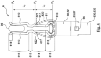
- Fig. 4 shows a front view of the receiving unit in a state in which a first contact element 90 is clamped in the first clamping unit, ie between the two clamping jaws 610.
- the two clamping jaws 610 are moved away from each other, so that in particular the contact sections 615 of the two clamping jaws 610 no longer touch each other.
- the contact element 90 touches the two clamping jaws 610 at the connection points P4 between the connection sections and opening sections 618 of the two receiving sections 616. An electrical contact is thus established between the first contact element 90 and the two clamping jaws 610.
- the distance L3 between the points P4 and P1 is also greater than the distance L2 between the points P2 and P3.
- the first spring element 620 exerts a force on the point P2 of the two clamping jaws.
- the points P4 and P3 each form abutments for the force, and the distances L3 and L2 each correspond to a force lever.
- the lever L3 is larger than the lever L2
- the spreading force at the point P3, i.e. the force effect of the foot section 613 on the first holding element 60 is increased at the point P3. This means that the foot sections 613 of the clamping jaws 610 are pressed more firmly against the holding element 60 in this case, and this increases the stability of the fastening between the clamping jaws 610 and the holding element 60.
- Fig. 5 shows an enlarged view of section X from Fig. 3A .
- the second clamping unit of the receiving unit 6 can be seen, in which a second contact element 80, preferably a busbar 80, is clamped.
- the second clamping unit comprises a clamping element 630 and a second spring element 640, as also shown in the Figures 2A to 3B can be seen.
- the clamping element 630 includes a first clamping section 631, a connecting clamping section 632, which adjoins the first clamping section 631, and a second clamping section 633, which adjoins the connecting clamping section 632.
- the first clamping section 631, the connecting clamping section 632 and the second clamping section 633 are each plate-shaped. Both the first clamping section 631 and the second clamping section 632 run perpendicular to the connecting clamping section 632, so that in particular the first clamping section 631 and the second clamping section 633 run parallel to each other.
- first clamping section 631 and the second clamping section 633 extend from the connecting clamping section 632 in the same direction, which is however opposite to the direction of extension of the first holding section 61 and the second holding section 63 starting from the connecting holding section 62, so that the holding element 60 and the clamping element 630 engage with each other.
- the second holding section 63, the connecting clamping section 632 and the second clamping section 633 form a receiving area in which a second contact element 80 can be received, as in Fig. 5
- the clamping element 630 can be made of the same material as the holding element 60.
- the clamping element 630 is fastened to the holding element 60, but is linearly movable relative to the holding element 60 along a clamping direction, wherein the clamping direction is perpendicular to the second holding section 63 and the first clamping section 631.
- This is made possible by the connection holding section 62 having a first opening 64 and the first clamping section 631 having a first projection 65 which engages in the first opening 64 and is arranged within the first opening 64 so as to be movable along the clamping direction, and by the connection clamping section 632 having a second opening 66 and the second holding section 63 having a second projection 67 which engages in the second opening 66 and is arranged within the second opening 66 so as to be movable along the clamping direction.
- the distance between the second holding section 63 and the second clamping section 633, and thus the size of the receiving area for the second contact element 80 can be changed.
- a second spring element 640 is arranged between the second holding section 63 and the first clamping section 631, which biases the holding element 60 and the clamping element 630 towards one another in order to contact a second contact element 80 inserted into the receiving area. More precisely, the second spring element 640 biases the second holding section 63 and the second clamping section 633 towards one another by biasing the first clamping section 631 and the second holding section 63 away from one another.
- the material of the second spring element 620 can be different from the material of the holding element 60 and the clamping element 630 and can be spring steel, for example.
- a second contact element 90 in the receiving area between the second holding section 63 and the second clamping section 633, for example, an external force can be exerted on the clamping element 630 so that the second clamping section 633 moves away from the second holding section 63. In doing so, the first clamping section 631 against the spring force of the second spring element 640 towards the second holding section 61, whereby the second spring element 640 is compressed. As a result, the second spring element 640 provides a counterforce that acts on the first clamping section 631. The second contact element 80 is then introduced into the space between the second holding section 63 and the second clamping section 633.
- the counterforce of the second spring element 640 causes the first clamping section 631 to move away from the second holding section 63 again and the second clamping section 633 to move towards the second holding section 63 until the second clamping section 633 and the second holding section 63 rest on opposite side surfaces of the second contact element 80, as in Fig. 5
- the counterforce of the second spring element 640 causes a clamping force from the second holding portion 63 and the second clamping portion 633 to the opposite side surfaces of the second contact element 80, which causes the second contact element to be held between the second holding portion 63 and the second clamping portion 633. In this way, the second contact element 80 is fastened and secured in the second clamping unit.
- Fig. 6 shows a further embodiment of the receiving unit 6 according to the invention, which comprises three first clamping units.
- Each of the three first clamping units is designed identically to the first clamping unit described above, and the second clamping unit is designed identically to the second clamping unit described above, so that reference is made to the above statements to avoid repetition.
- the holding element 60 is designed similarly to the holding element 60 described above, but the first holding section 61 is longer than in the above embodiment and comprises three recesses on each side, so that the two clamping jaws 610 of each of the three first clamping units can each be inserted into a pair of opposite recesses.
- a first contact element 90 can be inserted in each of the three first clamping units as described above.
- three first contact elements 90 and a second contact element 80 can be contacted simultaneously.
Landscapes
- Fuses (AREA)
- Measuring Leads Or Probes (AREA)
Applications Claiming Priority (1)
| Application Number | Priority Date | Filing Date | Title |
|---|---|---|---|
| DE102020125723.6A DE102020125723B3 (de) | 2020-10-01 | 2020-10-01 | Aufnahmeeinheit für ein kontaktelement sowie sicherungslasttrennschalter mit einer solchen aufnahmeeinheit |
Publications (2)
| Publication Number | Publication Date |
|---|---|
| EP3979293A1 EP3979293A1 (de) | 2022-04-06 |
| EP3979293B1 true EP3979293B1 (de) | 2025-02-26 |
Family
ID=78077992
Family Applications (1)
| Application Number | Title | Priority Date | Filing Date |
|---|---|---|---|
| EP21200211.7A Active EP3979293B1 (de) | 2020-10-01 | 2021-09-30 | Aufnahmeeinheit für sicherungslasttrennschalter |
Country Status (3)
| Country | Link |
|---|---|
| EP (1) | EP3979293B1 (pl) |
| DE (1) | DE102020125723B3 (pl) |
| PL (1) | PL3979293T3 (pl) |
Family Cites Families (7)
| Publication number | Priority date | Publication date | Assignee | Title |
|---|---|---|---|---|
| GB758301A (en) * | 1953-09-21 | 1956-10-03 | Telemecanique Electrique | Improvements in or relating to devices for making electrical connections |
| DE1741702U (de) | 1956-12-01 | 1957-03-21 | Wickmann Werke Ag | Sicherungsunterteil fuer schmelzeinsaetze mit kontaktmessern. |
| DE1059068B (de) * | 1957-11-08 | 1959-06-11 | Siemens Ag | Ein- oder mehrteiliges Lyrakontaktelement |
| DE7235571U (de) | 1972-09-27 | 1973-01-04 | Hensel G Kg | Kontaktsockel für NH-Sicherungspatronen |
| DE2932491A1 (de) | 1979-08-10 | 1981-02-12 | Geyer Gmbh & Co Christian | Kontaktvorrichtung fuer den messerkontakt eines sicherungseinsatzes |
| DE102008016902B3 (de) | 2008-04-02 | 2009-11-19 | Siemens Aktiengesellschaft | Schienenklemme |
| DE102018117723B4 (de) | 2018-07-23 | 2020-06-25 | Klaus Bruchmann Gmbh | Aufnahmeeinheit für kontaktstift in einem zähleranschlussblock sowie zähleranschlussblock und ein stromzähler |
-
2020
- 2020-10-01 DE DE102020125723.6A patent/DE102020125723B3/de active Active
-
2021
- 2021-09-30 EP EP21200211.7A patent/EP3979293B1/de active Active
- 2021-09-30 PL PL21200211.7T patent/PL3979293T3/pl unknown
Also Published As
| Publication number | Publication date |
|---|---|
| DE102020125723B3 (de) | 2022-02-10 |
| PL3979293T3 (pl) | 2025-05-26 |
| EP3979293A1 (de) | 2022-04-06 |
Similar Documents
| Publication | Publication Date | Title |
|---|---|---|
| EP3324490B1 (de) | Federklemmkontakt zur kontaktierung elektrischer leiter, leiteranschlussklemme und verfahren zur herstellung eines federklemmkontakts | |
| EP3454422B2 (de) | Leiteranschlussklemme | |
| DE102008060283B4 (de) | Werkzeuglos betätigbare Anschlussklemmvorrichtung mit mehreren Klemmarmen für mehrere elektrische Leiter | |
| EP3375045A1 (de) | Verbindungsklemme | |
| DE102018117723B4 (de) | Aufnahmeeinheit für kontaktstift in einem zähleranschlussblock sowie zähleranschlussblock und ein stromzähler | |
| DE10253858B4 (de) | Anschlußklemmelement und damit gebildete Anschlußklemme | |
| EP1680840B1 (de) | Flachsteckbuchse | |
| DE60001549T2 (de) | Elektrischer verbinder für ein ein/ausgabemodul | |
| EP3282518A1 (de) | Federkraftklemme zum anschluss eines elektrischen leiters | |
| EP3482460A1 (de) | Elektrischer hochleistungskontakt | |
| DE4016114C2 (de) | Elektrischer Mehrkontakt-Verbinder, der eine geringe Verbindungs- und Trennkraft erfordert | |
| EP3038213B1 (de) | Leiteranschlussklemme zum anklemmen wenigstens eines elektrischen leiters | |
| EP0865105A1 (de) | Steckbuchse bzw. elektrischer Steckverbinder mit Kontaktfeder und Steckbuchse als Anschlusskontakt | |
| EP3979293B1 (de) | Aufnahmeeinheit für sicherungslasttrennschalter | |
| EP0069045A2 (de) | Stecksockel für mehrpolige Niederspannungs-Schutzschalter | |
| WO2003036762A2 (de) | Elektrischer steckverbinder | |
| AT523557B1 (de) | Aufnahmeeinheit für Kontaktstift in einem Zähleranschlussblock und System mit einem Zähleranschlussblock und einer Überbrückungsvorrichtung | |
| EP1251538A2 (de) | Schmaler dreipoliger Sicherungslasttrennschalter | |
| EP0921611B1 (de) | Netzstromanschlussdose und -schalter | |
| DE102023208780A1 (de) | Kontaktanordnung, insbesondere für ein Elektrowerkzeug, System, Wechselakkupack, und Verbraucher | |
| DE2612490B2 (de) | Elektrische Mehrfachsteckdose | |
| DE202020105644U1 (de) | Aufnahmeeinheit für Sicherungslasttrennschalter | |
| EP0890969B1 (de) | Kontaktkörper zur Aufnahme eines Kontaktmessers eines Sicherungseinsatzes | |
| WO2016198352A1 (de) | Adapter zur elektrischen kontaktierung | |
| AT521504B1 (de) | Aufnahmeeinheit für einen Kontaktstift für einen Zähleranschlussblock sowie Zähleranschlussblock |
Legal Events
| Date | Code | Title | Description |
|---|---|---|---|
| PUAI | Public reference made under article 153(3) epc to a published international application that has entered the european phase |
Free format text: ORIGINAL CODE: 0009012 |
|
| STAA | Information on the status of an ep patent application or granted ep patent |
Free format text: STATUS: THE APPLICATION HAS BEEN PUBLISHED |
|
| AK | Designated contracting states |
Kind code of ref document: A1 Designated state(s): AL AT BE BG CH CY CZ DE DK EE ES FI FR GB GR HR HU IE IS IT LI LT LU LV MC MK MT NL NO PL PT RO RS SE SI SK SM TR |
|
| STAA | Information on the status of an ep patent application or granted ep patent |
Free format text: STATUS: REQUEST FOR EXAMINATION WAS MADE |
|
| 17P | Request for examination filed |
Effective date: 20221004 |
|
| RBV | Designated contracting states (corrected) |
Designated state(s): AL AT BE BG CH CY CZ DE DK EE ES FI FR GB GR HR HU IE IS IT LI LT LU LV MC MK MT NL NO PL PT RO RS SE SI SK SM TR |
|
| GRAP | Despatch of communication of intention to grant a patent |
Free format text: ORIGINAL CODE: EPIDOSNIGR1 |
|
| STAA | Information on the status of an ep patent application or granted ep patent |
Free format text: STATUS: GRANT OF PATENT IS INTENDED |
|
| INTG | Intention to grant announced |
Effective date: 20240924 |
|
| GRAS | Grant fee paid |
Free format text: ORIGINAL CODE: EPIDOSNIGR3 |
|
| GRAA | (expected) grant |
Free format text: ORIGINAL CODE: 0009210 |
|
| STAA | Information on the status of an ep patent application or granted ep patent |
Free format text: STATUS: THE PATENT HAS BEEN GRANTED |
|
| AK | Designated contracting states |
Kind code of ref document: B1 Designated state(s): AL AT BE BG CH CY CZ DE DK EE ES FI FR GB GR HR HU IE IS IT LI LT LU LV MC MK MT NL NO PL PT RO RS SE SI SK SM TR |
|
| P01 | Opt-out of the competence of the unified patent court (upc) registered |
Free format text: CASE NUMBER: APP_3201/2025 Effective date: 20250121 |
|
| REG | Reference to a national code |
Ref country code: GB Ref legal event code: FG4D Free format text: NOT ENGLISH |
|
| REG | Reference to a national code |
Ref country code: CH Ref legal event code: EP |
|
| REG | Reference to a national code |
Ref country code: DE Ref legal event code: R096 Ref document number: 502021006768 Country of ref document: DE |
|
| REG | Reference to a national code |
Ref country code: IE Ref legal event code: FG4D Free format text: LANGUAGE OF EP DOCUMENT: GERMAN |
|
| REG | Reference to a national code |
Ref country code: NL Ref legal event code: MP Effective date: 20250226 |
|
| PG25 | Lapsed in a contracting state [announced via postgrant information from national office to epo] |
Ref country code: RS Free format text: LAPSE BECAUSE OF FAILURE TO SUBMIT A TRANSLATION OF THE DESCRIPTION OR TO PAY THE FEE WITHIN THE PRESCRIBED TIME-LIMIT Effective date: 20250526 |
|
| PG25 | Lapsed in a contracting state [announced via postgrant information from national office to epo] |
Ref country code: FI Free format text: LAPSE BECAUSE OF FAILURE TO SUBMIT A TRANSLATION OF THE DESCRIPTION OR TO PAY THE FEE WITHIN THE PRESCRIBED TIME-LIMIT Effective date: 20250226 |
|
| PG25 | Lapsed in a contracting state [announced via postgrant information from national office to epo] |
Ref country code: ES Free format text: LAPSE BECAUSE OF FAILURE TO SUBMIT A TRANSLATION OF THE DESCRIPTION OR TO PAY THE FEE WITHIN THE PRESCRIBED TIME-LIMIT Effective date: 20250226 |
|
| REG | Reference to a national code |
Ref country code: LT Ref legal event code: MG9D |
|
| PG25 | Lapsed in a contracting state [announced via postgrant information from national office to epo] |
Ref country code: IS Free format text: LAPSE BECAUSE OF FAILURE TO SUBMIT A TRANSLATION OF THE DESCRIPTION OR TO PAY THE FEE WITHIN THE PRESCRIBED TIME-LIMIT Effective date: 20250626 Ref country code: NO Free format text: LAPSE BECAUSE OF FAILURE TO SUBMIT A TRANSLATION OF THE DESCRIPTION OR TO PAY THE FEE WITHIN THE PRESCRIBED TIME-LIMIT Effective date: 20250526 |
|
| PG25 | Lapsed in a contracting state [announced via postgrant information from national office to epo] |
Ref country code: NL Free format text: LAPSE BECAUSE OF FAILURE TO SUBMIT A TRANSLATION OF THE DESCRIPTION OR TO PAY THE FEE WITHIN THE PRESCRIBED TIME-LIMIT Effective date: 20250226 |
|
| PG25 | Lapsed in a contracting state [announced via postgrant information from national office to epo] |
Ref country code: HR Free format text: LAPSE BECAUSE OF FAILURE TO SUBMIT A TRANSLATION OF THE DESCRIPTION OR TO PAY THE FEE WITHIN THE PRESCRIBED TIME-LIMIT Effective date: 20250226 |
|
| PG25 | Lapsed in a contracting state [announced via postgrant information from national office to epo] |
Ref country code: PT Free format text: LAPSE BECAUSE OF FAILURE TO SUBMIT A TRANSLATION OF THE DESCRIPTION OR TO PAY THE FEE WITHIN THE PRESCRIBED TIME-LIMIT Effective date: 20250626 Ref country code: LV Free format text: LAPSE BECAUSE OF FAILURE TO SUBMIT A TRANSLATION OF THE DESCRIPTION OR TO PAY THE FEE WITHIN THE PRESCRIBED TIME-LIMIT Effective date: 20250226 |
|
| PG25 | Lapsed in a contracting state [announced via postgrant information from national office to epo] |
Ref country code: GR Free format text: LAPSE BECAUSE OF FAILURE TO SUBMIT A TRANSLATION OF THE DESCRIPTION OR TO PAY THE FEE WITHIN THE PRESCRIBED TIME-LIMIT Effective date: 20250527 Ref country code: BG Free format text: LAPSE BECAUSE OF FAILURE TO SUBMIT A TRANSLATION OF THE DESCRIPTION OR TO PAY THE FEE WITHIN THE PRESCRIBED TIME-LIMIT Effective date: 20250226 |
|
| PG25 | Lapsed in a contracting state [announced via postgrant information from national office to epo] |
Ref country code: SE Free format text: LAPSE BECAUSE OF FAILURE TO SUBMIT A TRANSLATION OF THE DESCRIPTION OR TO PAY THE FEE WITHIN THE PRESCRIBED TIME-LIMIT Effective date: 20250226 |
|
| PG25 | Lapsed in a contracting state [announced via postgrant information from national office to epo] |
Ref country code: SM Free format text: LAPSE BECAUSE OF FAILURE TO SUBMIT A TRANSLATION OF THE DESCRIPTION OR TO PAY THE FEE WITHIN THE PRESCRIBED TIME-LIMIT Effective date: 20250226 |
|
| PG25 | Lapsed in a contracting state [announced via postgrant information from national office to epo] |
Ref country code: DK Free format text: LAPSE BECAUSE OF FAILURE TO SUBMIT A TRANSLATION OF THE DESCRIPTION OR TO PAY THE FEE WITHIN THE PRESCRIBED TIME-LIMIT Effective date: 20250226 |
|
| PGFP | Annual fee paid to national office [announced via postgrant information from national office to epo] |
Ref country code: DE Payment date: 20250926 Year of fee payment: 5 |
|
| PG25 | Lapsed in a contracting state [announced via postgrant information from national office to epo] |
Ref country code: IT Free format text: LAPSE BECAUSE OF FAILURE TO SUBMIT A TRANSLATION OF THE DESCRIPTION OR TO PAY THE FEE WITHIN THE PRESCRIBED TIME-LIMIT Effective date: 20250226 |
|
| PGFP | Annual fee paid to national office [announced via postgrant information from national office to epo] |
Ref country code: PL Payment date: 20250908 Year of fee payment: 5 |
|
| PGFP | Annual fee paid to national office [announced via postgrant information from national office to epo] |
Ref country code: FR Payment date: 20250925 Year of fee payment: 5 |
|
| PG25 | Lapsed in a contracting state [announced via postgrant information from national office to epo] |
Ref country code: CZ Free format text: LAPSE BECAUSE OF FAILURE TO SUBMIT A TRANSLATION OF THE DESCRIPTION OR TO PAY THE FEE WITHIN THE PRESCRIBED TIME-LIMIT Effective date: 20250226 Ref country code: EE Free format text: LAPSE BECAUSE OF FAILURE TO SUBMIT A TRANSLATION OF THE DESCRIPTION OR TO PAY THE FEE WITHIN THE PRESCRIBED TIME-LIMIT Effective date: 20250226 |
|
| PG25 | Lapsed in a contracting state [announced via postgrant information from national office to epo] |
Ref country code: RO Free format text: LAPSE BECAUSE OF FAILURE TO SUBMIT A TRANSLATION OF THE DESCRIPTION OR TO PAY THE FEE WITHIN THE PRESCRIBED TIME-LIMIT Effective date: 20250226 |
|
| PG25 | Lapsed in a contracting state [announced via postgrant information from national office to epo] |
Ref country code: SK Free format text: LAPSE BECAUSE OF FAILURE TO SUBMIT A TRANSLATION OF THE DESCRIPTION OR TO PAY THE FEE WITHIN THE PRESCRIBED TIME-LIMIT Effective date: 20250226 |
|
| REG | Reference to a national code |
Ref country code: DE Ref legal event code: R097 Ref document number: 502021006768 Country of ref document: DE |
|
| PLBE | No opposition filed within time limit |
Free format text: ORIGINAL CODE: 0009261 |
|
| STAA | Information on the status of an ep patent application or granted ep patent |
Free format text: STATUS: NO OPPOSITION FILED WITHIN TIME LIMIT |
|
| 26N | No opposition filed |
Effective date: 20251127 |