EP3978865B1 - Optical interference measuring apparatus and optical interference measuring method - Google Patents
Optical interference measuring apparatus and optical interference measuring method Download PDFInfo
- Publication number
- EP3978865B1 EP3978865B1 EP20813602.8A EP20813602A EP3978865B1 EP 3978865 B1 EP3978865 B1 EP 3978865B1 EP 20813602 A EP20813602 A EP 20813602A EP 3978865 B1 EP3978865 B1 EP 3978865B1
- Authority
- EP
- European Patent Office
- Prior art keywords
- interferogram
- assumed
- model formula
- count
- unit
- Prior art date
- Legal status (The legal status is an assumption and is not a legal conclusion. Google has not performed a legal analysis and makes no representation as to the accuracy of the status listed.)
- Active
Links
Images


Classifications
-
- G—PHYSICS
- G01—MEASURING; TESTING
- G01B—MEASURING LENGTH, THICKNESS OR SIMILAR LINEAR DIMENSIONS; MEASURING ANGLES; MEASURING AREAS; MEASURING IRREGULARITIES OF SURFACES OR CONTOURS
- G01B9/00—Measuring instruments characterised by the use of optical techniques
- G01B9/02—Interferometers
- G01B9/02001—Interferometers characterised by controlling or generating intrinsic radiation properties
- G01B9/02002—Interferometers characterised by controlling or generating intrinsic radiation properties using two or more frequencies
- G01B9/02004—Interferometers characterised by controlling or generating intrinsic radiation properties using two or more frequencies using frequency scans
-
- G—PHYSICS
- G01—MEASURING; TESTING
- G01B—MEASURING LENGTH, THICKNESS OR SIMILAR LINEAR DIMENSIONS; MEASURING ANGLES; MEASURING AREAS; MEASURING IRREGULARITIES OF SURFACES OR CONTOURS
- G01B9/00—Measuring instruments characterised by the use of optical techniques
- G01B9/02—Interferometers
- G01B9/02083—Interferometers characterised by particular signal processing and presentation
- G01B9/02084—Processing in the Fourier or frequency domain when not imaged in the frequency domain
-
- G—PHYSICS
- G01—MEASURING; TESTING
- G01B—MEASURING LENGTH, THICKNESS OR SIMILAR LINEAR DIMENSIONS; MEASURING ANGLES; MEASURING AREAS; MEASURING IRREGULARITIES OF SURFACES OR CONTOURS
- G01B9/00—Measuring instruments characterised by the use of optical techniques
- G01B9/02—Interferometers
- G01B9/0209—Low-coherence interferometers
- G01B9/02091—Tomographic interferometers, e.g. based on optical coherence
-
- G—PHYSICS
- G01—MEASURING; TESTING
- G01N—INVESTIGATING OR ANALYSING MATERIALS BY DETERMINING THEIR CHEMICAL OR PHYSICAL PROPERTIES
- G01N21/00—Investigating or analysing materials by the use of optical means, i.e. using sub-millimetre waves, infrared, visible or ultraviolet light
- G01N21/01—Arrangements or apparatus for facilitating the optical investigation
-
- G—PHYSICS
- G01—MEASURING; TESTING
- G01N—INVESTIGATING OR ANALYSING MATERIALS BY DETERMINING THEIR CHEMICAL OR PHYSICAL PROPERTIES
- G01N21/00—Investigating or analysing materials by the use of optical means, i.e. using sub-millimetre waves, infrared, visible or ultraviolet light
- G01N21/17—Systems in which incident light is modified in accordance with the properties of the material investigated
- G01N21/41—Refractivity; Phase-affecting properties, e.g. optical path length
- G01N21/45—Refractivity; Phase-affecting properties, e.g. optical path length using interferometric methods; using Schlieren methods
-
- G—PHYSICS
- G01—MEASURING; TESTING
- G01N—INVESTIGATING OR ANALYSING MATERIALS BY DETERMINING THEIR CHEMICAL OR PHYSICAL PROPERTIES
- G01N21/00—Investigating or analysing materials by the use of optical means, i.e. using sub-millimetre waves, infrared, visible or ultraviolet light
- G01N21/17—Systems in which incident light is modified in accordance with the properties of the material investigated
- G01N21/47—Scattering, i.e. diffuse reflection
- G01N21/4795—Scattering, i.e. diffuse reflection spatially resolved investigating of object in scattering medium
Definitions
- the present invention relates to an optical interference measuring apparatus and an optical interference measuring method and, more particularly, to a Fourier domain optical interference measuring apparatus and a Fourier domain optical interference measuring method.
- OCT optical coherence tomography
- Patent Literature 1 discloses a swept source-OCT (SS-OCT) as an apparatus for performing FD-OCT measurement.
- SS-OCT swept source-OCT
- Patent Literature 2 an optical interference measuring apparatus and method having the features defined within the preamble of claims 1 and 5, respectively, is described.
- Literature 1 WO 2015/001918
- Literature 2 Seelamantula Chandra Sekhar et al.: "Super-Resolution Reconstruction in Frequency-Domain Optical-Coherence Tomography Using the Finite-Rate-of-Innovation Principle", IEEE Transactions on Signal Processing, IEEE, USA, vol. 62, no. 19, 1 October 2014, pages 5020-5029, XP011557578, ISSN: 1053-587X, DOI: 10.1109/TSP.2014.2340811 [retrieved on 2014-08-27 ]
- the resolution of an intensity spectrum in the depth direction of a three-dimensional measurement system using FD-OCT is limited by the frequency bandwidth of a light source. This is because fast Fourier transform is used when reconfiguring an interferogram into an intensity profile in the depth direction.
- an intensity profile as its Fourier transform should be obtained by a sequence of delta functions.
- the frequency bandwidth is a window function, and hence the convolution integral between its Fourier transform and the Fourier transform of an interferogram is obtained as an intensity profile.
- the present invention has been made in consideration of the above circumstances and has as its object to improve the resolution of an intensity profile in the depth direction in an optical interference measuring technique without using any broadband light source.
- optical interference measuring apparatus is defined by the features of claim 1.
- optical interference measuring method is defined by the features of claim 5.
- Preferred embodiments are defined by the features of claims 2 - 4.
- an optical interference measuring apparatus includes a measuring unit configured to acquire an interferogram of an interference wave by irradiating a measurement target and a reference surface with electromagnetic waves and causing a reflected wave from a reflecting surface of the measurement target to interfere with a reflected wave from the reference surface and a signal processing unit configured to configure an intensity profile in a depth direction by performing Fourier transform of the interferogram, the signal processing unit including a model parameter estimation unit configured to estimate, based on a model formula of an interferogram when it is assumed that a measurement target is a layered structure having at least one reflecting surface, a parameter for the model formula for each assumed surface count in a predetermined assumed surface count range, an optimal model selection unit configured to select an optimal model formula by a statistical technique from the model formula to which a parameter estimated for each of the assumed surface count is applied, and an intensity profile reconfiguration unit configured to reconfigure an intensity profile in the depth direction based on the optimal model formula.
- the model parameter estimation unit preferably estimates, based on a model formula of an interferogram when it is assumed that a measurement target is a layered structure having at least one reflecting surface count, with a refractive index in each layer being constant, a parameter for the model formula.
- the optimal model selection unit preferably reconfigures an interferogram by using the model formula to which a parameter estimated for each of the assumed surface count is applied, calculates a likelihood between the reconfigured interferogram and an original interferogram, and selects an optimal model formula based on an information amount criterion obtained by setting the assumed reflecting surface count as the degree of freedom.
- the assumed surface count range is preferably determined based on a structure characteristic of a measurement target.
- the assumed surface count range is preferably determined based on a peak count of an intensity profile in the depth direction which is configured by the original interferogram.
- An optical interference measuring method includes, inter alia, a step of configuring an intensity profile in a depth direction by irradiating a measurement target and a reference surface with electromagnetic waves and performing Fourier transform of an interferogram of an interference wave obtained by causing a reflected wave from a reflecting surface of the measurement target to interfere with a reflected wave from the reference surface, a step of estimating, based on a model formula of an interferogram when it is assumed that a measurement target is a layered structure having at least one reflecting surface count, a parameter for the model formula for each assumed surface count in a predetermined assumed surface count range, a step of selecting an optimal model formula by a statistical technique from the model formula to which a parameter estimated for each of the assumed surface count is applied, and a step of reconfiguring an intensity profile based on the optimal model formula.
- An optical interference measuring apparatus and an optical interference measuring method can improve the resolution of an intensity profile in the depth direction without using any broadband light source.
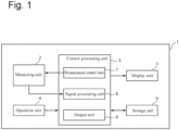
- Fig. 1 is a block diagram illustrating the schematic configuration of an optical interference measuring apparatus 1 according to an embodiment of the present invention.
- the optical interference measuring apparatus 1 is an SS-OCT, and this apparatus is used for, for example, the inspection of the internal structure of a concrete structure.
- the optical interference measuring apparatus 1 includes a measuring unit 2, a control processing unit 3, an operation unit 4, a display unit 5, and a storage unit 6.
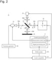
- Fig. 2 illustrates the schematic configuration of the measuring unit 2.
- the measuring unit 2 mainly includes a light source 21, a beam splitter 22, an automatic stage 23 for the installation of a measurement target, a reference surface 24, and a detector 25.
- the light source 21 is a variable frequency swept light source. This light source emits an electromagnetic beam while sweeping a wavelength at regular intervals within a predetermined wavelength band. It is possible to use, as the light source 21, an oscillation source such as an oscillation source using a Gunn diode or Shottkey barrier diode (SBD) which is a semiconductor material, and an oscillation source, based on frequency conversion using nonlinear crystal using a wavelength variable semiconductor laser (LD) as seed light. Alternatively, an oscillation source such as a TUNNET diode, resonance tunnel diode (RTD), or monolithic microwave IC (MMIC) may be used as the light source 21.
- an oscillation source such as a TUNNET diode, resonance tunnel diode (RTD), or monolithic microwave IC (MMIC) may be used as the light source 21.
- the beam splitter 22 is, for example, a beam splitter having a branching ratio of 50:50.
- the beam splitter 22 splits a light beam B from the light source 21 into measurement light B 1 and reference light B 2 .
- the automatic stage 23 holds a measurement target and sets a measurement surface.
- the measurement surface is a surface of a measurement target.
- the automatic stage 23 is configured such that the surface of the measurement target can move in the directions of two axes, that is, the X-axis and Y-axis, when a plane orthogonal to the optical axis of the measurement light B 1 is assumed to be an XY plane.
- the automatic stage 23 is driven and controlled by a measurement control unit (to be described later).
- the reference surface 24 is a mirror and reflects the reference light B 2 .
- the detector 25 is, for example, a Schottky barrier diode provided with a waveguide and an antenna and detects an interference signal between the reflected light of the reference light B 2 (to be described later) and the reflected light of the measurement light B 1 (to be described later).
- the light source 21 changes the frequency of the oscillator under the control of a measurement control unit 7.
- a lock-in amplifier 31 for detecting weak currents is connected to the detector 25.
- a function generator 29 applies On-Off modulation to the light source 21 to provide a reference signal to the lock-in amplifier 31 on the detector 25 side.
- Light emitted from the light source 21 enters the beam splitter 22 through a collimate lens 26a and is split into the measurement light B 1 and the reference light B 2 .
- the reference light B 2 propagates to the reference surface 24 while being collimated by a collimate lens 26b and is reflected by the reference surface 24. This light then propagates to the detector 25 through the beam splitter 22.
- the measurement light B 1 is shaped in terms of its beam shape by a collimate lens 26c and propagates to the measurement target.
- the light reflected by the reflecting surface of the measurement target then enters the beam splitter 22 again and propagates to the detector 25 through a collimate lens 26d.
- the "reflecting surface" of a measurement target includes the surface and the internal reflecting surface of the measurement target. Accordingly, the first reflecting surface means the surface of the measurement target.
- an interference pattern (interferogram) corresponding to the difference between the optical path length of the measurement light B 1 from the measurement target and the optical path length of the reference light B 2 is generated.
- the detector 25 detects the interference pattern.
- a DAQ system (data acquisition system) 32 samples and digitizes the detection signal and outputs the resultant signal as image data. This image data is the interferogram illustrated in Fig. 3 .
- the control processing unit 3 can refer to an arbitrary electrical circuit (or its part).
- the electrical circuit includes, for example, arbitrary numbers of electrical parts including resistors, transistors, capacitors, and inductors.
- This circuit may have an arbitrary form including, for example, an integrated circuit, an aggregate of integrated circuits, a microcontroller, a microprocessor, and an aggregate of electrical parts on a printed board (PCB).
- the control processing unit 3 may be incorporated in the housing of the optical interference measuring apparatus 1, a standalone device, or part of a discrete personal computer.
- the control processing unit 3 includes, as functional units, the measurement control unit 7 that controls measurement by the measuring unit 2, a signal processing unit 8 that processes a signal acquired by the measuring unit 2, and an output unit 9.
- the functions of the respective functional units including functional units further described in detail below may be implemented by circuits or by executing a program.
- the program may be stored in a recording medium such as a magnetic disk, flexible disk, optical disk, compact disk, Blu-ray (trademark registration) disk, or DVD.
- the measurement control unit 7 modulates the frequency of the light source 21. In addition, the measurement control unit 7 controls the driving of the automatic stage 23.
- the signal processing unit 8 performs processing for configuring an intensity profile from an interferogram. The signal processing unit 8 will be described in detail later.
- the output unit 9 displays the intensity profile generated by the signal processing unit 8 on the display unit 5 and stores the profile in the storage unit 6.
- the operation unit 4 is a device for allowing a user to input instructions to the optical interference measuring apparatus 1 and includes, for example, a mouse, a touch pad, a keyboard, an operation panel, a joystick, buttons, and switches, etc.
- the display unit 5 is, for example, a liquid crystal display and displays the intensity profile and other information generated by the signal processing unit 8.
- the signal processing unit 8 includes an FFT analysis unit 10, a super-resolution analysis unit 20, and a noise removal unit 30.
- the FFT analysis unit 10 reconfigures an intensity profile in the depth direction (hereinafter simply referred to as an "intensity profile") by performing fast Fourier transform of an interferogram. This method is a known method, and hence an explanation of the method will be omitted.
- the super-resolution analysis unit 20 includes a model parameter estimation unit 201, an optimal model selection unit 202, and an intensity profile reconfiguration unit 203.
- the model parameter estimation unit 201 models the interferogram measured by the optical interference measuring apparatus 1 and estimates parameters for the model formula.
- a virtual layered structure M without attenuation and dispersion which includes a reflecting surface count L of at least one, with a refraction index n 1 in each layer being constant.
- an interferogram I( ⁇ ) obtained by measuring the layered structure M can be expressed as follows. Note that in this case, "reflecting surface” is an interface between air and the layered structure M or between adjacent layers and a surface that reflects or internally reflects measurement light, that is, the surface of the layered structure M is the first reflecting surface.
- 2 is the intensity of a light source
- z is the distance to each layer
- l 1, 2, 3, ...
- L represents reflecting surface numbers up to L
- p 1, 2, 3,..., l represents reflecting surface numbers up to l.
- model formula (3) has three parameters, namely L, A l , and ⁇ l .
- the reflecting surface count L is assumed based on model formula (3), and the remaining parameters A l and ⁇ ⁇ are estimated as follows.
- An assumed reflecting surface count will be hereinafter referred to as an "assumed surface count.”
- the data count of D needs to satisfy K ⁇ 2L + 1.
- the actual measurement data that is, the data set of D k D ⁇ includes noise, and hence p is obtained by solving the following optimization problem. arg min p ⁇ D ⁇ p ⁇ 2 where p is the data set of p j .
- Equation (6) can be expanded into
- Equation (3) can be rewritten into the following matrix.
- the actual measurement data d ⁇ includes noise, and hence solving the following optimization problem (or Moore-Penrose pseudoinverse matrix) will obtain ⁇ , that is, (a set of) A l .
- the model parameter estimation unit 201 estimates the parameters A l and ⁇ 1 in the case of the assumed surface count L.
- the model parameter estimation unit 201 further calculates a measurement target reflection coefficient a 1 and an optical distance b 1 from the estimated parameters A l and ⁇ l .
- a l is obtained by calculating the absolute value of the obtained parameter A l .
- the range of the assumed surface counts L may be determined, for example, based on the structural characteristics of a measurement target. More specifically, a concrete structure such as a tunnel wall surface can be assumed to have a reflecting surface count falling within a predetermined range (for example, the range of 1 to 10) in terms of structure. For this reason, the optical interference measuring apparatus 1 may be configured to allow a user to input or set in advance the range of the assumed surface counts L of measurement targets (a minimum value L min of L and a maximum value L max of L) to the apparatus before measurement or computation.
- the model parameter estimation unit 201 estimates the model parameters A l and ⁇ l described above and computes the intensity profiles a l and b l with respect to each assumed surface count L within the range of the designated assumed surface counts L (for example, 1, 2,... 10) .
- the intensity profile reconfiguration unit 203 reconfigures the intensity profiles a 1 and b 1 from equations (15) and (16) obtained by the model parameter estimation unit 201.
- the optimal model selection unit 202 calculates the likelihood between the reconfigured interferogram reconfigured by substituting the parameters A l and ⁇ 1 corresponding to each reflecting surface count and estimated by the model parameter estimation unit 201 into model formula (3) and a measured interferogram obtained by measurement.
- the optimal model selection unit 202 selects an optimal model, i.e., the assumed surface count L constituting the optimal model, by applying the assumed surface count L as the degree of freedom to an information amount criterion based on the degree of freedom and the calculated likelihood.
- AIC Akaike's information criteria
- AICc finite correction AIC
- BIC Bayesian information amount criteria
- the noise removal unit 30 includes a first noise removal unit 301 and a second noise removal unit 302.
- an interferogram acquired in measurement by the optical interference measuring apparatus 1 theoretically has the shape illustrated in Fig. 3 .
- the interferogram includes noise as illustrated in Fig. 6(A) .
- Noise includes periodic noise originating from multireflection, etc., in the measurement system and random white Gaussian noise.
- the first noise removal unit 301 removes periodic noise.
- the second noise removal unit 302 removes white Gaussian noise.
- the FFT analysis unit 10 converts an interferogram into an intensity profile by fast Fourier transform (FFT). Converting an interferogram including noise as illustrated in Fig. 6(A) into an intensity profile by fast Fourier transform will find peaks, when the surface of a measurement target is set as a measurement target installation position, at positions other than in a region near the measurement target installation position, as illustrated in Fig. 6(B) . These peaks are periodic noise components.
- the first noise removal unit 301 multiples an intensity profile by a window function having, as a pass region, a region set with reference to the measurement target installation position at an optical distance in the depth direction of the measurement target and the remaining regions as deletion regions to perform filtering to delete data in the deletion regions.
- Fig. 6(C) illustrates an intensity profile obtained by filtering using a rectangular window.
- a pass region may be set by designating a predetermined section backward and forward with reference to a measurement target installation position with a surface position of the measurement target being set as the measurement target installation position. If, for example, the thickness of a measurement target is 10 mm and a surface position (measurement target installation position) of the measurement target is 100 mm, a pass region can be set at 50 mm before and after the measurement target installation position, i.e., in the range of 50 mm to 150 mm. As described above, the first noise removal unit 301 functions as a kind of bandpass filter.
- the middle position of a measurement target is set as a measurement target installation position
- the range obtained by adding a predetermined margin to half of the thickness of the measurement target before and after the measurement target installation position as a reference may be set as a pass region and the remaining regions may be set as deletion regions.
- a window function to be used is not limited to a rectangular window illustrated in Fig. 6(C) , and it is possible to use various types of window functions used for filtering, such as a Gaussian window, a Hann window, and a Hamming window.
- the first noise removal unit 301 converts the intensity profile obtained by deleting the data in the deletion regions into an interferogram, as illustrated in Fig. 6(D) , by inverse Fast Fourier transform (IFFT).
- IFFT inverse Fast Fourier transform
- the second noise removal unit 302 will be described.
- Fig. 7 is a graph for explaining white Gaussian noise removed by the second noise removal unit 302.
- the black line indicates a theoretical interferogram
- the gray line indicates an interferogram including white Gaussian noise.
- the theoretical interferogram and the interferogram including noise almost overlap each other.
- the envelope of the peaks of the theoretical interferogram has a continuous smooth waveform.
- the envelope of the interferogram including white Gaussian noise includes portions protruding randomly as indicated by the arrows and hence is not smoothly continuous.
- the second noise removal unit 302 deletes such noise in the following manner.
- Only the removal of a first noise component or the removal of a second noise component by singular value decomposition may be separately performed as follows.
- the influence of the first noise component is deemed to be larger and the influence of the second noise component is deemed to be smaller, only the removal of the first noise component is performed.
- the influence of the second noise component is deemed to be larger and the influence of the first noise component is deemed to be smaller, only the removal of the second noise component is performed.
- removal operations are preferably executed in the following manner, although the execution order is not specifically limited.
- the removal of the first noise component is performed first.
- the influence of the second noise component is deemed to be larger and the influence of the first noise component is deemed to be smaller, the removal of the second noise component is performed first.
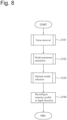
- Fig. 8 is a schematic flowchart for processing by the optical interference measuring method.
- the noise removal unit 30 removes noise from a measurement interferogram in step S101.
- the model parameter estimation unit 201 estimates parameters for a model by using the interferogram from which noise has been removed.
- the optimal model selection unit 202 selects an optimal model.
- the intensity profile reconfiguration unit 203 reconfigures an intensity profile in the depth direction. Processing in each step will be described in detail below.
- Fig. 9 is a flowchart for detailed processing associated with the noise removal in step S101.
- the first noise removal unit 301 removes noise by using a filter in step S201.
- the second noise removal unit 302 removes noise by singular value decomposition (SVD). Subsequently, the process shifts to step S102.
- SSD singular value decomposition
- Fig. 10 is a detailed flowchart for noise removal by the filter in step S201.
- the FFT analysis unit 10 converts a measurement interferogram into an intensity profile by fast Fourier transform in step S301.
- the first noise removal unit 301 sets, as a pass region, a region of the intensity profile with reference to a measurement target installation position, and also sets the remaining regions as deletion regions to perform filtering to delete data in the deletion regions.
- step S303 the first noise removal unit 301 converts the intensity profile after the filtering, which is obtained in step S302, into an interferogram by inverse fast Fourier transform and terminates the processing. Subsequently, the process shifts to step S202.
- Fig. 11 is a flowchart for detailed processing for noise removal by singular value decomposition in step S202.
- the second noise removal unit 302 creates a diagonal constant matrix D from the interferogram in step S401.
- step S402 the second noise removal unit 302 calculates a singular value diagonal matrix S (equation (18)) by performing singular value decomposition of the matrix D.
- step S403 the second noise removal unit 302 calculates an evaluation value V (equation (19)) from the singular value S.
- step S404 the second noise removal unit 302 compares the evaluation value V e with the predetermined threshold Th to determine whether the evaluation value V e is smaller than the threshold Th.
- the second noise removal unit 302 calculates a singular value S' by deleting a noise element from the singular value matrix S in step S405 (equation (20)).
- step S406 the interferogram matrix D ⁇ ' is reconfigured by using the singular value decomposition S' .
- the process then returns to step S402 to repeat steps S402 to S404.
- step S404 if it is determined in step S404 that the evaluation value V e is smaller than the threshold Th (YES), the interferogram D is set as an interferogram after the noise removal, and the processing is terminated. The process shifts to step S102.
- a repetition count may be set in advance and noise component removal may be repeated until the set count is satisfied.
- Fig. 12 is a detailed flowchart associated with the estimation of parameters for a model in step S102.
- the model parameter estimation unit 201 sets the range of the assumed surface counts L (that is, the minimum value L min and the maximum value L max ) based on user input, etc., in step S501.
- step S503 the model parameter estimation unit 201 calculates the parameter ⁇ l for model formula (3) by calculating equations (4) to (12) under the condition of the assumed surface count L min .
- step S504 the model parameter estimation unit 201 calculates the optical distance b l from the parameter ⁇ l obtained in step S503 by using equation (16) .
- step S505 the model parameter estimation unit 201 calculates the parameter A l from the interferogram and the parameter ⁇ l by calculating equations (12) to (14).
- step S506 the model parameter estimation unit 201 calculates the reflection coefficient a l from the parameter A l by using equation (15).
- step S507 the model parameter estimation unit 201 determines whether the assumed surface count L is equal to or more than L max , that is, analysis with each assumed surface count L within the range of the assumed surface counts L set in step S501 is thoroughly completed.
- Fig. 13 is a detailed flowchart associated with the selection of an optimal model in step S103.
- the optimal model selection unit 202 sets the range of the assumed surface counts L (that is, the minimum value L min and the maximum value L max ) set in step S501.
- step S604 the optimal model selection unit 202 calculates the likelihood between the measured interferogram from which noise has been removed in step S101 and the reconfigured interferogram in step S603.
- step S605 the optimal model selection unit 202 calculates an information amount criterion with respect to the assumed surface count L by setting the assumed surface count L as the degree of freedom and using the likelihood obtained in step S604.
- step S606 the optimal model selection unit 202 determines whether the assumed surface count L is equal to or more than L max , that is, analysis with all the assumed surface counts L within the range of the assumed surface counts L set in step S501 is completed.
- the optimal model selection unit 202 compares information amount criterion values corresponding to all the assumed surface counts L with each other to select a model with the assumed surface count L corresponding to the minimum information amount criterion value as an optimal model in step S607. The processing is then terminated.
- step S104 the assumed surface count corresponding to the selected optimal model is provided for the reconfiguration of an intensity profile by the intensity profile reconfiguration unit 203.
- the intensity profile reconfigured in this manner can be used for the analysis of the intensity profile in the depth direction.
- interferograms measured by scanning along the two axes i.e., the X-axis and the Y-axis, can be used for the configuration of a three-dimensional image.
- Fig. 14 illustrates the results of simulations of intensity profiles by the optical interference measuring apparatus 1 when the light source 21 is frequency-modulated with 600 GHz to 665 GHz.
- a measurement target was set such that the optical distance of the surface (first reflecting surface) was 80 mm.
- the upper, intermediate, and lower graphs each illustrate a result obtained when a sample had the structure illustrated in Table 1 and a constant refractive index of 1.53.
- Table 1 Simulation Conditions in Example 1 Fig. 14 Sample Structure Reflecting Surface Count Thickness (mm) Upper 2 10 Intermediate 2 5 Lower 2 1
- the gray lines each indicate the results of converting the same interferogram into an intensity profile only by fast Fourier transform.
- each gray line appears as having a broad peak, whereas each black line appears as having a sharp peak.
- the peak on the first surface and the peak on the second surface are separated from each other in the case of a thickness of 10 mm, overlap each other in the case of a thickness of 5 mm, and are not separated at all in the case of a thickness of 1 mm.
- the intensity profiles reconfigured based on the estimation of model parameters in this embodiment are separated from each other at any thickness.
- FIG. 15 illustrates results of noise removal by filter in step S201 using actually measured interferograms.
- the upper, intermediate, and lower graphs respectively indicate the results of experiments conducted under the conditions indicated in Table 2.
- the gray line indicates an interferogram before filtering.
- the gray line in Fig. 15(B) indicates the intensity profile obtained by fast Fourier transform of the interferogram before filtering.
- the black line in Fig. 15(B) indicates an intensity profile after the filtering.
- the black line in Fig. 15(A) indicates the interferogram obtained by inverse fast Fourier transform of the intensity profile after the filtering.
- noise not originating from the samples is accurately deleted by filtering upon setting pass regions with reference to the positions of the sample surfaces, that is, the sample installation positions, for samples of any thickness.
- periodic noise is deleted from the interferograms obtained by inverse fast Fourier transform of the intensity profiles after filtering.
- periodic noise can be removed from an interferogram in the following manner.
- the interferogram is Fourier transformed to configure an intensity profile.
- a pass region is set in the intensity profile with reference to the sample installation position to delete data in regions other than the pass region, thus filtering the intensity profile.
- Inverse Fourier transform is applied to the intensity profile after the filtering.
- Fig. 16 indicates the results obtained by noise removal based on singular value decomposition using an interferogram after noise removal by the above filter.
- each gray line indicates an interferogram before noise removal by singular value decomposition
- each black line indicates an interferogram after the noise removal by singular value decomposition.
- portions protruding from the envelopes before the noise removal are removed to obtain smoothly continuous envelopes, as is obviously indicated by the portions of the interferograms after the noise removal which are indicated by the arrows, in particular.
- random white Gaussian noise can be removed from an interferogram by generating a diagonal constant matrix from the interferogram, calculating a singular value diagonal matrix by performing singular value decomposition of the diagonal constant matrix, and deleting noise components from the singular value diagonal matrix.
- model parameters were estimated at each assumed surface count by using an interferogram after noise removal by singular value decomposition in the above actual measurement experiment and setting the range of the assumed surface counts L to 1 to 10.
- an interferogram was reconfigured at each assumed surface count by using the model parameters. The likelihood between the interferogram after the noise removal and the reconfigured interferogram was calculated, and an AIC value at each assumed surface count was obtained by setting the assumed surface count as the degree of freedom, thereby selecting a model exhibiting the minimum AIC value as an optimal model.
- the assumed surface counts L corresponding to the minimum AIC values were 7, 7, and 6 with thicknesses of 10 mm, 5 mm, and 1 mm, respectively.
- Fig. 17(A) illustrates intensity profiles.
- Each gray line indicates the intensity profile obtained by Fourier transform of an interferogram after noise removal by the singular value decomposition described above.
- Each black line indicates the intensity profile reconfigured based on the selected optimal model.
- Fig. 17(B) illustrates interferograms.
- Each gray line indicates the interferogram after noise removal by the singular value decomposition described above.
- Each black line indicates the interferogram reconfigured based on an optimal model.
- the intensity profile reconfigured based on an optimal model can be observed with higher resolution than the intensity profile generated by Fourier transform.
- peaks on the first and second reflecting surfaces can be separated from each other.
- the interferogram reconfigured from an optimal model can almost reproduce the interferogram after the noise removal as input data.
- an interferogram is reconfigured by using a model formula to which the parameters estimated with respect to each assumed surface count are applied, the likelihood between the reconfigured interferogram and the original interferogram is calculated, and an optimal model formula is selected based on the information amount criterion obtained by setting an assumed surface count as the degree of freedom, thereby reconfiguring an intensity profile by using the optimal model formula.
- an intensity profile in the depth direction can be measured with higher resolution than that based on a technique using general Fourier transform.
- the optical interference measuring method includes a noise removal method of removing noise and a super-resolution analysis method of reconfiguring an intensity profile based on an optimal model upon estimating model parameters and selecting the optimal model.
- the noise removal method includes a noise removal method using a filter and a noise removal method based on singular value decomposition.
- these methods each can independently produce an effect and only the noise removal operation may be performed for the purpose of noise removal.
- only the super-resolution analysis method may be performed for the purpose of improving the resolution. Executing together the noise removal method and the super-resolution analysis method will noticeably improve the resolution, thus providing an advantageous effect.
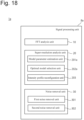
- FIG. 18 is a functional configuration view of a signal processing unit 8a of an optical interference measuring apparatus 1a according to this modification.
- the optical interference measuring apparatus 1a has a configuration almost similar to that of the optical interference measuring apparatus 1 but differs from the optical interference measuring apparatus 1 in that the signal processing unit 8a includes a model parameter estimation unit 201a and an optimal model selection unit 202a instead of the model parameter estimation unit 201 and the optimal model selection unit 202, respectively.
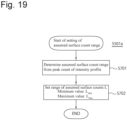
- the model parameter estimation unit 201a performs the processing illustrated in Fig. 19 instead of step S501 in estimating model parameters. That is, when the setting of the range of the assumed surface counts L starts, the model parameter estimation unit 201a refers to the intensity profile obtained by Fourier transform of an interferogram by the FFT analysis unit 10 (for example, in step S301, etc.) to determine an assumed surface count based on a peak count in step S701. More specifically, when two peaks are confirmed as indicated by the gray line in Fig. 14 , the range of peak counts of 2 ⁇ 5 (note, however, that the assumed surface count L is a natural number) is set, and the range of the assumed surface counts is determined as 1 to 7.
- step S702 the range of the assumed surface counts L (that is, the minimum value L min and the maximum value L max ) is set based on the above determination, and the processing is terminated. The process then shifts to step S502.
- the optimal model selection unit 202a also has a configuration similar to that described above.
- This configuration makes it possible to automatically set a proper range of the assumed surface counts L, thereby facilitating a measuring operation.
- the present invention is not limited to the above embodiment and may include various changes.
- the above embodiment has been described in detail for a better understanding of the present invention.
- the present invention is not limited to an apparatus including all the configurations described above.
- the above description concerns the optical interference measuring apparatus which is an SS-OCT.
- the present invention is not limited to this and can be applied to an optical interference measuring apparatus such as an SD-OCT configured to obtain an intensity profile in the depth direction by Fourier transform.
- other components may be added, deleted, or replaced. The scope of protection is defined by the claims.
Landscapes
- Physics & Mathematics (AREA)
- General Physics & Mathematics (AREA)
- General Health & Medical Sciences (AREA)
- Health & Medical Sciences (AREA)
- Immunology (AREA)
- Analytical Chemistry (AREA)
- Chemical & Material Sciences (AREA)
- Life Sciences & Earth Sciences (AREA)
- Pathology (AREA)
- Biochemistry (AREA)
- Engineering & Computer Science (AREA)
- Signal Processing (AREA)
- Nuclear Medicine, Radiotherapy & Molecular Imaging (AREA)
- Radiology & Medical Imaging (AREA)
- Mathematical Physics (AREA)
- Optics & Photonics (AREA)
- Investigating Or Analysing Materials By Optical Means (AREA)
- Instruments For Measurement Of Length By Optical Means (AREA)
- Length Measuring Devices By Optical Means (AREA)
Applications Claiming Priority (2)
| Application Number | Priority Date | Filing Date | Title |
|---|---|---|---|
| JP2019100827A JP7381827B2 (ja) | 2019-05-30 | 2019-05-30 | 光干渉測定装置および光干渉測定方法 |
| PCT/JP2020/020582 WO2020241583A1 (ja) | 2019-05-30 | 2020-05-25 | 光干渉測定装置および光干渉測定方法 |
Publications (3)
| Publication Number | Publication Date |
|---|---|
| EP3978865A1 EP3978865A1 (en) | 2022-04-06 |
| EP3978865A4 EP3978865A4 (en) | 2022-07-06 |
| EP3978865B1 true EP3978865B1 (en) | 2024-08-28 |
Family
ID=73546103
Family Applications (1)
| Application Number | Title | Priority Date | Filing Date |
|---|---|---|---|
| EP20813602.8A Active EP3978865B1 (en) | 2019-05-30 | 2020-05-25 | Optical interference measuring apparatus and optical interference measuring method |
Country Status (5)
| Country | Link |
|---|---|
| US (1) | US12000699B2 (enExample) |
| EP (1) | EP3978865B1 (enExample) |
| JP (1) | JP7381827B2 (enExample) |
| CN (1) | CN113892024B (enExample) |
| WO (1) | WO2020241583A1 (enExample) |
Family Cites Families (17)
| Publication number | Priority date | Publication date | Assignee | Title |
|---|---|---|---|---|
| JP4409384B2 (ja) * | 2004-08-03 | 2010-02-03 | 株式会社トプコン | 光画像計測装置及び光画像計測方法 |
| JP4622564B2 (ja) * | 2005-02-10 | 2011-02-02 | 凸版印刷株式会社 | 膜厚測定方法 |
| WO2007057016A1 (en) * | 2005-11-16 | 2007-05-24 | Chemometec A/S | Determination of chemical or physical properties of sample or component of a sample |
| WO2008080127A2 (en) * | 2006-12-22 | 2008-07-03 | Zygo Corporation | Apparatus and method for measuring characteristics of surface features |
| JP4389032B2 (ja) | 2007-01-18 | 2009-12-24 | 国立大学法人 筑波大学 | 光コヒーレンストモグラフィーの画像処理装置 |
| JP2009115503A (ja) * | 2007-11-02 | 2009-05-28 | Lasertec Corp | 粗さ測定方法及び粗さ測定装置 |
| JP2009115474A (ja) * | 2007-11-02 | 2009-05-28 | Lasertec Corp | 多層膜構造観察方法及び多層膜構造観察装置 |
| US8340455B2 (en) | 2008-03-31 | 2012-12-25 | University Of Central Florida Research Foundation, Inc. | Systems and methods for performing Gabor-domain optical coherence microscopy |
| DE102009045130B3 (de) * | 2009-09-29 | 2011-03-31 | Carl Zeiss Ag | Verfahren zur Bestimmung der inneren Struktur einer Probe |
| WO2013018024A1 (en) * | 2011-07-29 | 2013-02-07 | Ecole Polytechnique Federale De Lausanne (Epfl) | Apparatus and method for quantitative phase tomography through linear scanning with coherent and non-coherent detection |
| US9251604B2 (en) | 2012-07-20 | 2016-02-02 | Samsung Electronics Co., Ltd. | Apparatus and method for generating tomography image |
| AU2012268876A1 (en) | 2012-12-24 | 2014-07-10 | Canon Kabushiki Kaisha | Non-linear solution for 2D phase shifting |
| JP2016176689A (ja) | 2013-07-04 | 2016-10-06 | 株式会社日立ハイテクノロジーズ | 干渉測定方法、及びその装置 |
| WO2016054079A1 (en) * | 2014-09-29 | 2016-04-07 | Zyomed Corp. | Systems and methods for blood glucose and other analyte detection and measurement using collision computing |
| CN104523239B (zh) * | 2015-01-12 | 2017-02-22 | 南京理工大学 | 全深度谱域光学相干层析成像装置及方法 |
| CN109157187A (zh) * | 2018-09-06 | 2019-01-08 | 中国科学院上海光学精密机械研究所 | 增加扫频光学相干层析成像系统成像深度范围的方法 |
| JP6999908B2 (ja) | 2019-05-30 | 2022-01-19 | 株式会社トプコン | 光干渉測定装置および光干渉測定方法 |
-
2019
- 2019-05-30 JP JP2019100827A patent/JP7381827B2/ja active Active
-
2020
- 2020-05-25 US US17/614,880 patent/US12000699B2/en active Active
- 2020-05-25 CN CN202080036899.6A patent/CN113892024B/zh active Active
- 2020-05-25 WO PCT/JP2020/020582 patent/WO2020241583A1/ja not_active Ceased
- 2020-05-25 EP EP20813602.8A patent/EP3978865B1/en active Active
Also Published As
| Publication number | Publication date |
|---|---|
| US12000699B2 (en) | 2024-06-04 |
| CN113892024B (zh) | 2025-08-15 |
| EP3978865A1 (en) | 2022-04-06 |
| WO2020241583A1 (ja) | 2020-12-03 |
| US20220228850A1 (en) | 2022-07-21 |
| EP3978865A4 (en) | 2022-07-06 |
| JP7381827B2 (ja) | 2023-11-16 |
| JP2020193919A (ja) | 2020-12-03 |
| CN113892024A (zh) | 2022-01-04 |
Similar Documents
| Publication | Publication Date | Title |
|---|---|---|
| EP3978864A1 (en) | Optical interferometer and optical interferometry method | |
| Jepsen | Phase retrieval in terahertz time-domain measurements: a “how to” tutorial | |
| US7825667B2 (en) | Microwave imaging system and processes, and associated software products | |
| CN114144108B (zh) | 散射断层成像装置以及散射断层成像方法 | |
| JP2013535675A5 (enExample) | ||
| US20110299849A1 (en) | Method and apparatus for synthesizing and correcting phase distortions in ultra-wide bandwidth optical waveforms | |
| CN102792136B (zh) | 太赫波测量装置和测量方法 | |
| Arz et al. | Traceable coplanar waveguide calibrations on fused silica substrates up to 110 GHz | |
| US10009114B2 (en) | Method and system for controlling phase of a signal | |
| US20130077084A1 (en) | Object characteristic measuring system | |
| WO2016132452A1 (ja) | テラヘルツ波計測装置、テラヘルツ波計測方法及びコンピュータプログラム | |
| EP3978865B1 (en) | Optical interference measuring apparatus and optical interference measuring method | |
| Huffman | IMERG V06 quality index | |
| Clifton | Precision slotted-line impedance measurements using computer simulation for data correction | |
| CN101449590A (zh) | 用于去除光学断面图像线条的系统和方法 | |
| US12174115B2 (en) | Resolving absolute depth in circular-ranging optical coherence tomography | |
| TW201140008A (en) | Apparatus, method and computer-readable storage medium for processing a signal in a spectrometer system | |
| Gerth et al. | Regularized differential evolution for a blind phase retrieval problem in ultrashort laser pulse characterization | |
| Barajas et al. | Towards an on-chip signal processing solution for the online calibration of SS-OCT systems | |
| Nan et al. | Fast iterative reconstruction algorithm for microwave-induced thermoacoustic imaging | |
| CN100523721C (zh) | 表面地形的重新构建 | |
| Shahir et al. | Permittivity profile estimation based on non-radiating equivalent source (2d case) | |
| Jansz et al. | Characterizing the resolvability of real superluminescent diode sources for application to optical coherence tomography using a low coherence interferometry model | |
| Harmon et al. | Adaptive refinement for scattered field quantities of interest for the coupled EFIE-MFIE | |
| JP6522414B2 (ja) | 光周波数コム装置を用いたレーザ周波数測定装置の評価方法 |
Legal Events
| Date | Code | Title | Description |
|---|---|---|---|
| STAA | Information on the status of an ep patent application or granted ep patent |
Free format text: STATUS: THE INTERNATIONAL PUBLICATION HAS BEEN MADE |
|
| PUAI | Public reference made under article 153(3) epc to a published international application that has entered the european phase |
Free format text: ORIGINAL CODE: 0009012 |
|
| STAA | Information on the status of an ep patent application or granted ep patent |
Free format text: STATUS: REQUEST FOR EXAMINATION WAS MADE |
|
| 17P | Request for examination filed |
Effective date: 20211221 |
|
| AK | Designated contracting states |
Kind code of ref document: A1 Designated state(s): AL AT BE BG CH CY CZ DE DK EE ES FI FR GB GR HR HU IE IS IT LI LT LU LV MC MK MT NL NO PL PT RO RS SE SI SK SM TR |
|
| A4 | Supplementary search report drawn up and despatched |
Effective date: 20220608 |
|
| RIC1 | Information provided on ipc code assigned before grant |
Ipc: G01N 21/47 20060101ALI20220601BHEP Ipc: G01B 9/02091 20220101ALI20220601BHEP Ipc: G01B 9/02004 20220101ALI20220601BHEP Ipc: G01N 21/17 20060101ALI20220601BHEP Ipc: G01B 9/02 20220101AFI20220601BHEP |
|
| DAV | Request for validation of the european patent (deleted) | ||
| DAX | Request for extension of the european patent (deleted) | ||
| GRAP | Despatch of communication of intention to grant a patent |
Free format text: ORIGINAL CODE: EPIDOSNIGR1 |
|
| STAA | Information on the status of an ep patent application or granted ep patent |
Free format text: STATUS: GRANT OF PATENT IS INTENDED |
|
| INTG | Intention to grant announced |
Effective date: 20240307 |
|
| RIC1 | Information provided on ipc code assigned before grant |
Ipc: G01N 21/47 20060101ALI20240222BHEP Ipc: G01B 9/02091 20220101ALI20240222BHEP Ipc: G01B 9/02004 20220101ALI20240222BHEP Ipc: G01N 21/17 20060101ALI20240222BHEP Ipc: G01B 9/02 20060101AFI20240222BHEP |
|
| GRAS | Grant fee paid |
Free format text: ORIGINAL CODE: EPIDOSNIGR3 |
|
| GRAA | (expected) grant |
Free format text: ORIGINAL CODE: 0009210 |
|
| STAA | Information on the status of an ep patent application or granted ep patent |
Free format text: STATUS: THE PATENT HAS BEEN GRANTED |
|
| AK | Designated contracting states |
Kind code of ref document: B1 Designated state(s): AL AT BE BG CH CY CZ DE DK EE ES FI FR GB GR HR HU IE IS IT LI LT LU LV MC MK MT NL NO PL PT RO RS SE SI SK SM TR |
|
| REG | Reference to a national code |
Ref country code: CH Ref legal event code: EP |
|
| REG | Reference to a national code |
Ref country code: DE Ref legal event code: R096 Ref document number: 602020036779 Country of ref document: DE |
|
| REG | Reference to a national code |
Ref country code: IE Ref legal event code: FG4D |
|
| REG | Reference to a national code |
Ref country code: LT Ref legal event code: MG9D |
|
| PG25 | Lapsed in a contracting state [announced via postgrant information from national office to epo] |
Ref country code: NO Free format text: LAPSE BECAUSE OF FAILURE TO SUBMIT A TRANSLATION OF THE DESCRIPTION OR TO PAY THE FEE WITHIN THE PRESCRIBED TIME-LIMIT Effective date: 20241128 |
|
| REG | Reference to a national code |
Ref country code: AT Ref legal event code: MK05 Ref document number: 1718376 Country of ref document: AT Kind code of ref document: T Effective date: 20240828 |
|
| PG25 | Lapsed in a contracting state [announced via postgrant information from national office to epo] |
Ref country code: NL Free format text: LAPSE BECAUSE OF FAILURE TO SUBMIT A TRANSLATION OF THE DESCRIPTION OR TO PAY THE FEE WITHIN THE PRESCRIBED TIME-LIMIT Effective date: 20240828 Ref country code: PL Free format text: LAPSE BECAUSE OF FAILURE TO SUBMIT A TRANSLATION OF THE DESCRIPTION OR TO PAY THE FEE WITHIN THE PRESCRIBED TIME-LIMIT Effective date: 20240828 Ref country code: GR Free format text: LAPSE BECAUSE OF FAILURE TO SUBMIT A TRANSLATION OF THE DESCRIPTION OR TO PAY THE FEE WITHIN THE PRESCRIBED TIME-LIMIT Effective date: 20241129 Ref country code: PT Free format text: LAPSE BECAUSE OF FAILURE TO SUBMIT A TRANSLATION OF THE DESCRIPTION OR TO PAY THE FEE WITHIN THE PRESCRIBED TIME-LIMIT Effective date: 20241230 Ref country code: FI Free format text: LAPSE BECAUSE OF FAILURE TO SUBMIT A TRANSLATION OF THE DESCRIPTION OR TO PAY THE FEE WITHIN THE PRESCRIBED TIME-LIMIT Effective date: 20240828 |
|
| PG25 | Lapsed in a contracting state [announced via postgrant information from national office to epo] |
Ref country code: BG Free format text: LAPSE BECAUSE OF FAILURE TO SUBMIT A TRANSLATION OF THE DESCRIPTION OR TO PAY THE FEE WITHIN THE PRESCRIBED TIME-LIMIT Effective date: 20240828 |
|
| PG25 | Lapsed in a contracting state [announced via postgrant information from national office to epo] |
Ref country code: LV Free format text: LAPSE BECAUSE OF FAILURE TO SUBMIT A TRANSLATION OF THE DESCRIPTION OR TO PAY THE FEE WITHIN THE PRESCRIBED TIME-LIMIT Effective date: 20240828 |
|
| REG | Reference to a national code |
Ref country code: NL Ref legal event code: MP Effective date: 20240828 |
|
| PG25 | Lapsed in a contracting state [announced via postgrant information from national office to epo] |
Ref country code: AT Free format text: LAPSE BECAUSE OF FAILURE TO SUBMIT A TRANSLATION OF THE DESCRIPTION OR TO PAY THE FEE WITHIN THE PRESCRIBED TIME-LIMIT Effective date: 20240828 Ref country code: IS Free format text: LAPSE BECAUSE OF FAILURE TO SUBMIT A TRANSLATION OF THE DESCRIPTION OR TO PAY THE FEE WITHIN THE PRESCRIBED TIME-LIMIT Effective date: 20241228 |
|
| PG25 | Lapsed in a contracting state [announced via postgrant information from national office to epo] |
Ref country code: HR Free format text: LAPSE BECAUSE OF FAILURE TO SUBMIT A TRANSLATION OF THE DESCRIPTION OR TO PAY THE FEE WITHIN THE PRESCRIBED TIME-LIMIT Effective date: 20240828 |
|
| PG25 | Lapsed in a contracting state [announced via postgrant information from national office to epo] |
Ref country code: RS Free format text: LAPSE BECAUSE OF FAILURE TO SUBMIT A TRANSLATION OF THE DESCRIPTION OR TO PAY THE FEE WITHIN THE PRESCRIBED TIME-LIMIT Effective date: 20241128 Ref country code: ES Free format text: LAPSE BECAUSE OF FAILURE TO SUBMIT A TRANSLATION OF THE DESCRIPTION OR TO PAY THE FEE WITHIN THE PRESCRIBED TIME-LIMIT Effective date: 20240828 |
|
| PG25 | Lapsed in a contracting state [announced via postgrant information from national office to epo] |
Ref country code: RS Free format text: LAPSE BECAUSE OF FAILURE TO SUBMIT A TRANSLATION OF THE DESCRIPTION OR TO PAY THE FEE WITHIN THE PRESCRIBED TIME-LIMIT Effective date: 20241128 Ref country code: PT Free format text: LAPSE BECAUSE OF FAILURE TO SUBMIT A TRANSLATION OF THE DESCRIPTION OR TO PAY THE FEE WITHIN THE PRESCRIBED TIME-LIMIT Effective date: 20241230 Ref country code: PL Free format text: LAPSE BECAUSE OF FAILURE TO SUBMIT A TRANSLATION OF THE DESCRIPTION OR TO PAY THE FEE WITHIN THE PRESCRIBED TIME-LIMIT Effective date: 20240828 Ref country code: NO Free format text: LAPSE BECAUSE OF FAILURE TO SUBMIT A TRANSLATION OF THE DESCRIPTION OR TO PAY THE FEE WITHIN THE PRESCRIBED TIME-LIMIT Effective date: 20241128 Ref country code: NL Free format text: LAPSE BECAUSE OF FAILURE TO SUBMIT A TRANSLATION OF THE DESCRIPTION OR TO PAY THE FEE WITHIN THE PRESCRIBED TIME-LIMIT Effective date: 20240828 Ref country code: LV Free format text: LAPSE BECAUSE OF FAILURE TO SUBMIT A TRANSLATION OF THE DESCRIPTION OR TO PAY THE FEE WITHIN THE PRESCRIBED TIME-LIMIT Effective date: 20240828 Ref country code: IS Free format text: LAPSE BECAUSE OF FAILURE TO SUBMIT A TRANSLATION OF THE DESCRIPTION OR TO PAY THE FEE WITHIN THE PRESCRIBED TIME-LIMIT Effective date: 20241228 Ref country code: HR Free format text: LAPSE BECAUSE OF FAILURE TO SUBMIT A TRANSLATION OF THE DESCRIPTION OR TO PAY THE FEE WITHIN THE PRESCRIBED TIME-LIMIT Effective date: 20240828 Ref country code: GR Free format text: LAPSE BECAUSE OF FAILURE TO SUBMIT A TRANSLATION OF THE DESCRIPTION OR TO PAY THE FEE WITHIN THE PRESCRIBED TIME-LIMIT Effective date: 20241129 Ref country code: FI Free format text: LAPSE BECAUSE OF FAILURE TO SUBMIT A TRANSLATION OF THE DESCRIPTION OR TO PAY THE FEE WITHIN THE PRESCRIBED TIME-LIMIT Effective date: 20240828 Ref country code: ES Free format text: LAPSE BECAUSE OF FAILURE TO SUBMIT A TRANSLATION OF THE DESCRIPTION OR TO PAY THE FEE WITHIN THE PRESCRIBED TIME-LIMIT Effective date: 20240828 Ref country code: BG Free format text: LAPSE BECAUSE OF FAILURE TO SUBMIT A TRANSLATION OF THE DESCRIPTION OR TO PAY THE FEE WITHIN THE PRESCRIBED TIME-LIMIT Effective date: 20240828 Ref country code: AT Free format text: LAPSE BECAUSE OF FAILURE TO SUBMIT A TRANSLATION OF THE DESCRIPTION OR TO PAY THE FEE WITHIN THE PRESCRIBED TIME-LIMIT Effective date: 20240828 |
|
| PG25 | Lapsed in a contracting state [announced via postgrant information from national office to epo] |
Ref country code: SM Free format text: LAPSE BECAUSE OF FAILURE TO SUBMIT A TRANSLATION OF THE DESCRIPTION OR TO PAY THE FEE WITHIN THE PRESCRIBED TIME-LIMIT Effective date: 20240828 Ref country code: RO Free format text: LAPSE BECAUSE OF FAILURE TO SUBMIT A TRANSLATION OF THE DESCRIPTION OR TO PAY THE FEE WITHIN THE PRESCRIBED TIME-LIMIT Effective date: 20240828 Ref country code: DK Free format text: LAPSE BECAUSE OF FAILURE TO SUBMIT A TRANSLATION OF THE DESCRIPTION OR TO PAY THE FEE WITHIN THE PRESCRIBED TIME-LIMIT Effective date: 20240828 |
|
| PG25 | Lapsed in a contracting state [announced via postgrant information from national office to epo] |
Ref country code: EE Free format text: LAPSE BECAUSE OF FAILURE TO SUBMIT A TRANSLATION OF THE DESCRIPTION OR TO PAY THE FEE WITHIN THE PRESCRIBED TIME-LIMIT Effective date: 20240828 |
|
| PG25 | Lapsed in a contracting state [announced via postgrant information from national office to epo] |
Ref country code: CZ Free format text: LAPSE BECAUSE OF FAILURE TO SUBMIT A TRANSLATION OF THE DESCRIPTION OR TO PAY THE FEE WITHIN THE PRESCRIBED TIME-LIMIT Effective date: 20240828 |
|
| PG25 | Lapsed in a contracting state [announced via postgrant information from national office to epo] |
Ref country code: SK Free format text: LAPSE BECAUSE OF FAILURE TO SUBMIT A TRANSLATION OF THE DESCRIPTION OR TO PAY THE FEE WITHIN THE PRESCRIBED TIME-LIMIT Effective date: 20240828 Ref country code: IT Free format text: LAPSE BECAUSE OF FAILURE TO SUBMIT A TRANSLATION OF THE DESCRIPTION OR TO PAY THE FEE WITHIN THE PRESCRIBED TIME-LIMIT Effective date: 20240828 |
|
| REG | Reference to a national code |
Ref country code: DE Ref legal event code: R097 Ref document number: 602020036779 Country of ref document: DE |
|
| PLBE | No opposition filed within time limit |
Free format text: ORIGINAL CODE: 0009261 |
|
| STAA | Information on the status of an ep patent application or granted ep patent |
Free format text: STATUS: NO OPPOSITION FILED WITHIN TIME LIMIT |
|
| PGFP | Annual fee paid to national office [announced via postgrant information from national office to epo] |
Ref country code: DE Payment date: 20250521 Year of fee payment: 6 |
|
| PGFP | Annual fee paid to national office [announced via postgrant information from national office to epo] |
Ref country code: CH Payment date: 20250601 Year of fee payment: 6 |
|
| 26N | No opposition filed |
Effective date: 20250530 |
|
| PG25 | Lapsed in a contracting state [announced via postgrant information from national office to epo] |
Ref country code: SE Free format text: LAPSE BECAUSE OF FAILURE TO SUBMIT A TRANSLATION OF THE DESCRIPTION OR TO PAY THE FEE WITHIN THE PRESCRIBED TIME-LIMIT Effective date: 20240828 |