EP3978149B1 - Device for sorting parcels with system for permutation of containers in vertical rotation in sorting output - Google Patents
Device for sorting parcels with system for permutation of containers in vertical rotation in sorting output Download PDFInfo
- Publication number
- EP3978149B1 EP3978149B1 EP21192440.2A EP21192440A EP3978149B1 EP 3978149 B1 EP3978149 B1 EP 3978149B1 EP 21192440 A EP21192440 A EP 21192440A EP 3978149 B1 EP3978149 B1 EP 3978149B1
- Authority
- EP
- European Patent Office
- Prior art keywords
- sorting
- receptacle
- rotation
- axis
- parcel
- Prior art date
- Legal status (The legal status is an assumption and is not a legal conclusion. Google has not performed a legal analysis and makes no representation as to the accuracy of the status listed.)
- Active
Links
- 238000001514 detection method Methods 0.000 claims description 10
- 230000004044 response Effects 0.000 claims description 6
- 230000001360 synchronised effect Effects 0.000 claims description 3
- 230000003100 immobilizing effect Effects 0.000 claims 1
- 238000000034 method Methods 0.000 description 2
- 241000863032 Trieres Species 0.000 description 1
- 230000005484 gravity Effects 0.000 description 1
- 230000008676 import Effects 0.000 description 1
- 238000009434 installation Methods 0.000 description 1
- 230000008569 process Effects 0.000 description 1
- 238000011084 recovery Methods 0.000 description 1
- 230000009467 reduction Effects 0.000 description 1
Images


Classifications
-
- B—PERFORMING OPERATIONS; TRANSPORTING
- B07—SEPARATING SOLIDS FROM SOLIDS; SORTING
- B07C—POSTAL SORTING; SORTING INDIVIDUAL ARTICLES, OR BULK MATERIAL FIT TO BE SORTED PIECE-MEAL, e.g. BY PICKING
- B07C5/00—Sorting according to a characteristic or feature of the articles or material being sorted, e.g. by control effected by devices which detect or measure such characteristic or feature; Sorting by manually actuated devices, e.g. switches
- B07C5/36—Sorting apparatus characterised by the means used for distribution
-
- B—PERFORMING OPERATIONS; TRANSPORTING
- B07—SEPARATING SOLIDS FROM SOLIDS; SORTING
- B07C—POSTAL SORTING; SORTING INDIVIDUAL ARTICLES, OR BULK MATERIAL FIT TO BE SORTED PIECE-MEAL, e.g. BY PICKING
- B07C3/00—Sorting according to destination
- B07C3/02—Apparatus characterised by the means used for distribution
Definitions
- the invention relates to parcel sorting equipment comprising a sorting conveyor, sorting outlets distributed along said conveyor and a control-command unit capable of controlling the sorting conveyor to sort the parcels in the sorting outlets according to of some sorting information.
- a control-command unit here controls the sorting conveyor to sort the parcels in the sorting outlets according to certain sorting information, here their destination address.
- PPI small import packages
- the present invention relates to sorting equipment contributing to solving the problems mentioned above.
- the subject of the invention is parcel sorting equipment comprising a sorting conveyor, sorting outlets distributed along said conveyor and a control-command unit capable of controlling the sorting conveyor to sort the parcels in the sorting outlets according to certain sorting information, each sorting outlet being arranged to store a plurality of sorting receptacles each associated with parcel sorting information in the memory of the control-command unit, characterized in that the equipment also comprises at each sorting outlet a receptacle permutation device comprising a rotatable shaft about a first horizontal axis of rotation, the shaft being provided with supports each designed to store and drive in vertical rotation around the first axis of rotation a receptacle for parcels, and in that the control-command unit controls the changeover device to immobilize a receptacle, whose parcel sorting information has associated in the memory of the control-command unit corresponds to the sorting information of a current parcel to be sorted, in a filling position in which the receptacle is positioned under the
- each physical sorting outlet of the sorting equipment is equipped with several receptacles each associated with different sorting information.
- a receptacle permutation system is also provided to move the receptacles of the sorting outlet in rotation and to position a single one in the filling position under the appropriate sorting outlet.
- the sorting equipment according to the invention will be able to serve as many logic outputs as there are receptacles assigned to the physical sorting output and this for a footprint equivalent to that of conventional sorting equipment.
- the invention consists on the one hand in reducing the footprint by proposing a system for permutation of tray with vertical rotation and on the other hand in keeping the receptacles horizontal during their vertical rotation using a mechanical horizontal synchronization system.
- the receptacles are thus constantly kept horizontal despite the random distribution of the load flow of the packages in the receptacles.
- the figure 1 represents sorting equipment 1 for parcels 2 according to the invention designed to equip a sorting center such as a logistics center for receiving and redistributing parcels 2.
- the sorting equipment 1 of parcels 2 comprises a sorting conveyor 3, here for example a loop conveyor which moves along a certain conveying direction D1, and sorting outlets 4 distributed along the conveyor of sorting 3.
- a sorting conveyor 3 here for example a loop conveyor which moves along a certain conveying direction D1
- sorting outlets 4 distributed along the conveyor of sorting 3.
- the sorting conveyor 3 comprises pivoting plates 5 capable of pivoting to let the parcels 2 fall by gravity into the appropriate sorting outlets 4.
- Each sorting outlet 4 is equipped with a plurality of receptacles 6 for parcels 2, the number of which may vary depending on the sorting information of parcels to be sorted, such as for example the number of destination addresses for parcels 2 to be sorted , the size of the packages, the weight of the parcels, mention of a customs declaration on the parcels, etc.
- the receptacles 6 are for example in the form of trays open on the top, as shown in the figures 2 to 4 .
- This type of receptacle 6 is particularly well suited to bulk filling with packages 2 of small size, called PPI.
- the receptacles 6 are each associated with parcel sorting information 2 in the memory of a control-command unit 7 of the sorting equipment 1.
- the control-command unit 7, as shown in the figure 1 also includes in memory a sorting plan for the parcels 2 to be sorted which is defined from the distribution of all the receptacles 6 and the sorting outlets 4 within the sorting equipment 1 and from the information of sorting of all the parcels 2 to be sorted.
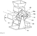
- a permutation device 8 of the receptacles 6 shown on all of the figures 1 to 4 is also provided at each sorting outlet 4 and comprises a shaft 8a rotatable along a first horizontal axis of rotation A1.
- the shaft 8a is here provided with supports 9 each designed to store and drive in vertical rotation around the first axis of rotation A1 a receptacle 6 for parcel 2.
- the supports 9 are for example in the form of nacelles with a bottom wall PF designed to support a receptacle, two side walls PL and two openings on the front face and rear face designed to allow the unloading of a receptacle by sliding.
- Shaft 8a is also designed to move in the clockwise or counterclockwise, as represented by the arrow R1 on the figures 1 to 4 , and to immobilize after each rotation, a receptacle 6 in a filling position in which the receptacle 6 is arranged under the sorting outlet 4 to receive a parcel 2 and another receptacle in a discharge position in which this other receptacle 6 , represented in figure 2 , is placed at the height of an operator's arm to be evacuated manually or automatically by a shuttle robot.
- Shaft 8a also includes a plurality of arms 8b extending from the first axis of rotation.
- Each support 9 is here mounted free in rotation at one end of an arm 8b along a second horizontal axis of rotation A2 offset with respect to the first axis of rotation A1, each support 9 being mounted in horizontal equilibrium with respect to the second axis of rotation A2 deported.
- the permutation device 8 also comprises a mechanical horizontal synchronization system 10 designed to synchronize all of the supports 9 in horizontal equilibrium during their vertical rotation along the first axis of rotation A1.
- the mechanical horizontal synchronization system 10 comprises here, by way of example, a frame 11 on which the shaft 8a is rotatably mounted along the first axis of rotation A1, a reference pinion 12 secured to the frame and sharing the first axis of rotation with the shaft 8a, a synchronization pinion 13 secured to the support 9 and mounted free in rotation at the end of each arm 8b along the second axis of rotation A2, and mechanical connections 14 connecting in synchronized rotation the synchronization pinions 13 to the reference pinion 12.
- the mechanical links 14 are in the form of a synchronization link 14a of the chain or toothed belt type connecting in series all the synchronization sprockets 13 and of a reference link 14b of the chain or toothed belt type connecting the reference gear with a single synchronization gear.
- the mechanical links 14 are only in the form of reference links 14b of the chain or toothed belt type connecting each synchronization pinion 13 independently to the reference pinion 12.
- the control-command unit 7 is parameterized to control the switching device 8 on the basis of the sorting information of the parcels 2 to be sorted and of the sorting plan.
- the unit 7 controls the permutation device 8 in order to place in the filling position a receptacle 6 whose parcel 2 sorting information associated with it corresponds to the sorting information of a current parcel 2 to be sorted. in sort output 4.
- the switching device 8 here has a barrel-shaped structure clearly visible on the figures 1 to 4 .
- each sorting outlet 4 is equipped with a filling hopper 15 which extends downwards, from the sorting conveyor 3 towards a receptacle 6 in the position of filling.
- a fairing here partially represented by the frame 11, may be provided around the changeover device in order to protect the operators during the recovery of a receptacle loaded with packages in the evacuation position.
- an opening will be provided in the fairing at arm's length so that the operator can easily retrieve the receptacle loaded with packages.
- a position detection system 16 of receptacle 6 can also be fitted to switching device 8 in order to determine which receptacle 6 is in the filling position.
- control-command unit 7 includes in memory the scheduling of the receptacles 6 at the level of each sorting outlet 4 and, in response to the detection of said position detection system 16, controls the rotation R1 of the device permutation 8 to place the receptacle 6 in the filling position, the parcel sorting information of which corresponds to the current parcel 2 sorting information to be sorted.
- the sorting equipment 1 may also comprise a system for detecting the filling level 17 of the receptacle 6 when it is in the filling position.
- the unit of control-command 7 controls the movement of the receptacle 6 in the evacuation position.
- the drive in rotation R1 of the shaft is carried out using a motor 18 controlled step by step and a toothed belt.
- control-command unit 7 first interrogates the position detection system 16 of the receptacle 6 .
- the parcel 2 is evacuated in the receptacle 6.
- the permutation system 8 moves the receptacles 6 in rotation R1 to position the receptacle 6 in the filling position with the corresponding parcel 2 sorting information.
- the switching device 8 does not have time to position the correct receptacle 6 in time, the parcel 2 is recirculated on the sorting conveyor 3.
- control-command unit 7 then interrogates the system for detecting the filling level 17 of the receptacle 6.
- control-command unit 7 prohibits any evacuation of parcels 2 in this receptacle 6 and controls the switching device 8 to position the receptacle 6 in the evacuation position and allow its manual or automatic evacuation and its replacement by an empty receptacle 6.
- control-command unit 7 controls the rotation of the receptacles 6 to place the appropriate receptacle 6 in the filling position and allow the evacuation of the package 2.
Description
L'invention concerne un équipement de tri de colis comprenant un convoyeur de tri, des sorties de tri réparties le long dudit convoyeur et une unité de contrôle-commande apte à commander le convoyeur de tri pour trier les colis dans les sorties de tri en fonction d'une certaine information de tri.The invention relates to parcel sorting equipment comprising a sorting conveyor, sorting outlets distributed along said conveyor and a control-command unit capable of controlling the sorting conveyor to sort the parcels in the sorting outlets according to of some sorting information.
Les plateformes logistiques sont aujourd'hui équipées de systèmes automatisés de tri de colis afin de traiter des colis en provenance de nombreuses sources d'approvisionnement et de les distribuer vers un grand nombre de destinataires.Today, logistics platforms are equipped with automated parcel sorting systems in order to process parcels from many supply sources and distribute them to a large number of recipients.
Les documents
Une unité de contrôle-commande commande ici le convoyeur de tri pour trier les colis dans les sorties de tri en fonction d'une certaine information de tri, ici leur adresse de destination.A control-command unit here controls the sorting conveyor to sort the parcels in the sorting outlets according to certain sorting information, here their destination address.
L'augmentation actuelle du volume d'achat via le e-commerce des petits paquets imports, dits PPI, nécessite d'augmenter le nombre de passes de tri et la vitesse de débit des convoyeurs avec le risque de détériorer les colis.The current increase in the volume of purchases via e-commerce of small import packages, known as PPI, requires increasing the number of sorting passes and the throughput speed of the conveyors with the risk of damaging the packages.
En parallèle, l'augmentation du nombre de destinations physiques sur un même plan de tri nécessite d'augmenter le nombre de sorties de tri et donc l'emprise au sol de l'installation.At the same time, increasing the number of physical destinations on the same sorting plan requires increasing the number of sorting outlets and therefore the footprint of the installation.
Aussi, plus le nombre de sorties de tri sera important et plus les moyens de manutention mis en œuvre pour récupérer les colis devront être importants.Also, the greater the number of sorting outlets, the greater the handling means implemented to recover the packages will have to be.
La présente invention a pour objet un équipement de tri contribuant à résoudre les problèmes mentionnés cidessus.The present invention relates to sorting equipment contributing to solving the problems mentioned above.
A cet effet, l'invention a pour objet un équipement de tri de colis comprenant un convoyeur de tri, des sorties de tri réparties le long dudit convoyeur et une unité de contrôle-commande apte à commander le convoyeur de tri pour trier les colis dans les sorties de tri en fonction d'une certaine information de tri, chaque sortie de tri étant agencée pour stocker une pluralité de réceptacles de tri chacun associé à une information de tri de colis en mémoire de l'unité de contrôle-commande, caractérisé en ce que l'équipement comprend également à chaque sortie de tri un dispositif de permutation des réceptacles comprenant un arbre mobile en rotation selon un premier axe de rotation horizontal, l'arbre étant muni de supports chacun conçus pour stocker et entrainer en rotation verticale autour du premier axe de rotation un réceptacle pour colis, et en ce que l'unité de contrôle-commande commande le dispositif de permutation pour immobiliser un réceptacle, dont l'information de tri de colis associée en mémoire de l'unité de contrôle-commande correspond à l'information de tri d'un colis courant à trier, dans une position de remplissage dans laquelle le réceptacle est positionné sous la sortie de tri pour réceptionner un colis.To this end, the subject of the invention is parcel sorting equipment comprising a sorting conveyor, sorting outlets distributed along said conveyor and a control-command unit capable of controlling the sorting conveyor to sort the parcels in the sorting outlets according to certain sorting information, each sorting outlet being arranged to store a plurality of sorting receptacles each associated with parcel sorting information in the memory of the control-command unit, characterized in that the equipment also comprises at each sorting outlet a receptacle permutation device comprising a rotatable shaft about a first horizontal axis of rotation, the shaft being provided with supports each designed to store and drive in vertical rotation around the first axis of rotation a receptacle for parcels, and in that the control-command unit controls the changeover device to immobilize a receptacle, whose parcel sorting information has associated in the memory of the control-command unit corresponds to the sorting information of a current parcel to be sorted, in a filling position in which the receptacle is positioned under the sorting outlet to receive a parcel.
L'équipement de tri de colis selon l'invention peut avantageusement présenter les caractéristiques suivantes :
- l'arbre comprend une pluralité de bras s'étendant depuis le premier axe de rotation et chaque bras comprend un des supports monté libre en rotation selon un second axe de rotation horizontal déporté par rapport au premier axe de rotation, chaque support étant monté en équilibre horizontal par rapport à l'axe de rotation déporté ;
- le dispositif de permutation comprend un système de synchronisation horizontale mécanique conçu pour synchroniser l'ensemble des supports en équilibre horizontal pendant leur rotation verticale selon le premier axe de rotation ;
- le système de synchronisation horizontale mécanique comprend un châssis sur lequel est monté mobile en rotation l'arbre selon le premier axe de rotation, un pignon de référence solidaire au châssis et partageant le premier axe de rotation avec l'arbre, un pignon de synchronisation solidaire au support et monté libre en rotation à l'extrémité de chaque bras selon le second axe de rotation, et des liaisons mécaniques reliant en rotation synchronisée les pignons de synchronisation au pignon de référence ;
- les liaisons mécaniques comprennent une liaison de synchronisation de type chaine ou courroie crantée reliant en série l'ensemble des pignons de synchronisation et une liaison de référence de type chaîne ou courroie crantée reliant le pignon de référence à un seul pignon de synchronisation ;
- les liaisons mécaniques comprennent des liaisons de référence de type chaîne ou courroie crantée reliant chaque pignon de synchronisation indépendamment au pignon de synchronisation ;
- les supports se présentent sous la forme de nacelles avec une paroi de fond conçue pour supporter un réceptacle, deux parois latérales et deux ouvertures en face avant et arrière conçues pour autoriser le déchargement d'un réceptacle par glissement ;
- le dispositif de permutation comprend un système de détection de position de réceptacle apte à déterminer quel réceptacle de la sortie de tri est en position de remplissage, l'unité de contrôle-commande comprenant en mémoire l'ordonnancement des réceptacles au niveau de chaque sortie de tri et, en réponse à la détection dudit système de détection, commande la rotation du dispositif de permutation pour placer en position de remplissage le réceptacle dont l'information de tri de colis correspond à l'information de tri du colis courant à trier ;
- le dispositif de permutation comprend un système de détection du niveau de remplissage de réceptacle en position de remplissage, et, en réponse au dépassement d'un certain seuil du niveau de remplissage du réceptacle, l'unité de contrôle-commande commande le déplacement du réceptacle dans une position d'évacuation agencée pour présenter le réceptacle à hauteur ergonomique ;
- chaque sortie de tri est équipée d'une trémie de remplissage qui s'étend vers le bas depuis le convoyeur vers un réceptacle en position de remplissage.
- the shaft comprises a plurality of arms extending from the first axis of rotation and each arm comprises one of the supports mounted free to rotate along a second horizontal axis of rotation offset with respect to the first axis of rotation, each support being mounted in equilibrium horizontal with respect to the offset axis of rotation;
- the permutation device comprises a mechanical horizontal synchronization system designed to synchronize all of the supports in horizontal balance during their vertical rotation along the first axis of rotation;
- the mechanical horizontal synchronization system comprises a frame on which the shaft is rotatably mounted along the first axis of rotation, a reference pinion fixed to the frame and sharing the first axis of rotation with the shaft, a synchronization pinion fixed to the support and mounted free in rotation at the end of each arm along the second axis of rotation, and mechanical connections connecting in synchronized rotation the synchronization pinions to the reference pinion;
- the mechanical links comprise a chain or toothed belt type synchronization link connecting all of the synchronization sprockets in series and a chain or toothed belt type reference link connecting the reference pinion to a single synchronization pinion;
- the mechanical links comprise reference links of the chain or toothed belt type connecting each synchronization pinion independently to the synchronization pinion;
- the supports are in the form of nacelles with a bottom wall designed to support a receptacle, two side walls and two openings in the front and rear face designed to allow the unloading of a receptacle by sliding;
- the permutation device comprises a receptacle position detection system capable of determining which receptacle of the sorting outlet is in the filling position, the control-command unit comprising in memory the scheduling of the receptacles at the level of each outlet of sorting and, in response to the detection of said detection system, controls the rotation of the switching device to place in the filling position the receptacle whose parcel sorting information corresponds to the sorting information of the current parcel to be sorted;
- the switching device comprises a system for detecting the level of filling of the receptacle in the filling position, and, in response to the exceeding of a certain threshold of the level of filling of the receptacle, the control-command unit controls the movement of the receptacle in an evacuation position arranged to present the receptacle at an ergonomic height;
- each sorting outlet is equipped with a filling hopper which extends downwards from the conveyor towards a receptacle in the filling position.
L'idée à la base de l'invention est ici d'avoir un nombre de sorties de tri dites logiques, ou potentielles, plus important que le nombre de sorties de tri physiques. Pour cela chaque sortie de tri physique de l'équipement de tri est équipée de plusieurs réceptacles associés chacun à des informations de tri différentes.The basic idea of the invention here is to have a greater number of so-called logical or potential sorting outputs than the number of physical sorting outputs. For this, each physical sorting outlet of the sorting equipment is equipped with several receptacles each associated with different sorting information.
Un système de permutation de réceptacles est également prévu pour déplacer en rotation les réceptacles de la sortie de tri et pour en positionner un seul en position de remplissage sous la sortie de tri appropriée.A receptacle permutation system is also provided to move the receptacles of the sorting outlet in rotation and to position a single one in the filling position under the appropriate sorting outlet.
On comprendra par exemple que pour une sortie de tri physique comprenant quatre réceptacles associés chacun à une information de tri de colis différente, il y aura trois sorties logiques de plus qu'une simple sortie de tri physique munie d'un seul réceptacle.It will be understood for example that for a physical sorting outlet comprising four receptacles each associated with different parcel sorting information, there will be three more logic outputs than a simple physical sorting outlet provided with a single receptacle.
Ainsi, l'équipement de tri selon l'invention pourra desservir autant de sorties logiques que de réceptacles affectés à la sortie de tri physique et ce pour une emprise au sol équivalente à celle d'équipement de tri classique.Thus, the sorting equipment according to the invention will be able to serve as many logic outputs as there are receptacles assigned to the physical sorting output and this for a footprint equivalent to that of conventional sorting equipment.
L'invention consiste d'une part à réduire l'emprise au sol en proposant un système de permutation de bac à rotation verticale et d'autre part à maintenir les réceptacles à l'horizontal pendant leur rotation verticale à l'aide d'un système de synchronisation horizontale mécanique.The invention consists on the one hand in reducing the footprint by proposing a system for permutation of tray with vertical rotation and on the other hand in keeping the receptacles horizontal during their vertical rotation using a mechanical horizontal synchronization system.
Les réceptacles sont ainsi constamment maintenus à l'horizontal malgré la répartition aléatoire et du flux de chargement des colis dans les réceptacles.The receptacles are thus constantly kept horizontal despite the random distribution of the load flow of the packages in the receptacles.
La présente invention sera mieux comprise et d'autres avantages apparaîtront à la lecture de la description détaillée de modes de réalisation pris à titre d'exemples nullement limitatifs et illustrés par les dessins annexés, dans lesquels :
- [
Fig.1 ] Lafigure 1 est une représentation schématique d'un équipement de tri selon l'invention ; - [
Fig.2 ] Lafigure 2 est une représentation schématique de la face latérale gauche d'un dispositif de permutation selon l'invention ; - [
Fig.3 ] Lafigure 3 est une représentation schématique de la face latérale droite d'un dispositif de permutation selon un premier mode de réalisation de l'invention ; - [
Fig.4 ] Lafigure 4 est une représentation schématique de la face latérale droite d'un dispositif de permutation selon un second mode de réalisation de l'invention. Description détaillée
- [
Fig.1 ] Thefigure 1 is a schematic representation of sorting equipment according to the invention; - [
Fig.2 ] Thefigure 2 is a schematic representation of the left side face of a switching device according to the invention; - [
Fig.3 ] Thefigure 3 is a schematic representation of the right side face of a switching device according to a first embodiment of the invention; - [
Fig.4 ] Thefigure 4 is a schematic representation of the right side face of a switching device according to a second embodiment of the invention. detailed description
La
L'équipement de tri 1 de colis 2 selon l'invention comprend un convoyeur de tri 3, ici par exemple un convoyeur à boucle qui se déplace selon une certain direction de convoyage D1, et des sorties de tri 4 réparties le long du convoyeur de tri 3.The
Le convoyeur de tri 3 comprend des plateaux 5 pivotants aptes à pivoter pour laisser chuter par gravité les colis 2 dans les sorties de tri 4 appropriées.The sorting
Chaque sortie de tri 4 est équipée d'une pluralité de réceptacles 6 pour colis 2, dont le nombre peut varier en fonction des informations de tri de colis à trier, tels que par exemple le nombre d'adresses de destination de colis 2 à trier, la dimension des colis, le poids des colis, la mention d'une déclaration de douane sur les colis, etc.Each
Les réceptacles 6 se présentent par exemple sous la forme de bacs ouverts sur le dessus, comme représenté sur les
Ce type de réceptacles 6 est particulièrement bien adapté au remplissage en vrac par des colis 2 de petites taille, dits PPI.This type of
Les réceptacles 6 sont chacun associés à une information de tri de colis 2 en mémoire d'une unité de contrôle-commande 7 de l'équipement de tri 1.The
L'unité de contrôle-commande 7, telle que représentée sur la
Un dispositif de permutation 8 des réceptacles 6 représenté sur l'ensemble des
L'arbre 8a est ici muni de supports 9 chacun conçus pour stocker et entrainer en rotation verticale autour du premier axe de rotation A1 un réceptacle 6 pour colis 2. Les supports 9 se présentent par exemple sous la forme de nacelles avec une paroi de fond PF conçue pour supporter un réceptacle, deux parois latérales PL et deux ouvertures en face avant et face arrière conçues pour autoriser le déchargement d'un réceptacle par glissement. L'arbre 8a est également conçu pour se déplacer dans le sens horaire ou antihoraire, comme représenté par la flèche R1 sur les
L'arbre 8a comprend également une pluralité de bras 8b s'étendant depuis le premier axe de rotation.Shaft 8a also includes a plurality of
Chaque support 9 est ici monté libre en rotation à une extrémité d'un bras 8b selon un second axe de rotation A2 horizontal déporté par rapport au premier axe de rotation A1, chaque support 9 étant monté en équilibre horizontal par rapport au second axe de rotation A2 déporté.Each
Le dispositif de permutation 8 comprend également un système de synchronisation horizontale mécanique 10 conçu pour synchroniser l'ensemble des supports 9 en équilibre horizontal pendant leur rotation verticale selon le premier axe de rotation A1.The
Plus particulièrement, le système de synchronisation horizontale mécanique 10 comprend ici à titre d'exemple un châssis 11 sur lequel est monté mobile en rotation l'arbre 8a selon le premier axe de rotation A1, un pignon de référence 12 solidaire au châssis et partageant le premier axe de rotation avec l'arbre 8a, un pignon de synchronisation 13 solidaire au support 9 et monté libre en rotation à l'extrémité de chaque bras 8b selon le second axe de rotation A2, et des liaisons mécaniques 14 reliant en rotation synchronisée les pignons de synchronisation 13 au pignon de référence 12.More particularly, the mechanical
Selon un premier mode de réalisation représenté sur les
Selon un second mode de réalisation représenté sur la
L'unité de contrôle-commande 7 est paramétrée pour commander le dispositif de permutation 8 sur la base des informations de tri des colis 2 à trier et du plan de tri.The control-
Ainsi, l'unité 7 commande le dispositif de permutation 8 afin de placer en position de remplissage un réceptacle 6 dont l'information de tri de colis 2 qui lui est associée correspond à l'information de tri d'un colis 2 courant à trier dans la sortie de tri 4.Thus, the
De manière avantageuse, le dispositif de permutation 8 présente ici une structure en forme de barillet bien visible sur les
On comprendra donc que l'augmentation du nombre de réceptacles par sortie physique augmente le nombre de sorties logiques, favorisant de fait la diminution du nombre de passes de tri sur le convoyeur de tri 3.It will therefore be understood that the increase in the number of receptacles per physical output increases the number of logic outputs, thereby favoring the reduction in the number of sorting passes on the sorting
Aussi, afin de faciliter le transfert des colis 2 dans les réceptacles 6, chaque sortie de tri 4 est équipée d'une trémie 15 de remplissage qui s'étend vers le bas, depuis le convoyeur de tri 3 vers un réceptacle 6 en position de remplissage.Also, in order to facilitate the transfer of the
De manière avantageuse, un carénage, ici partiellement représenté par le châssis 11, pourra être prévu autour du dispositif de permutation afin de protéger les opérateurs lors de la récupération d'un réceptacle chargé en colis en position d'évacuation.Advantageously, a fairing, here partially represented by the
Dans ce cas, une ouverture sera prévue dans le carénage à hauteur de bras afin que l'opérateur puisse récupérer facilement le réceptacle chargé en colis.In this case, an opening will be provided in the fairing at arm's length so that the operator can easily retrieve the receptacle loaded with packages.
Comme représenté sur la
Dans ce cas, l'unité de contrôle-commande 7 comprend en mémoire l'ordonnancement des réceptacles 6 au niveau de chaque sortie de tri 4 et, en réponse à la détection dudit système de détection de position 16, commande la rotation R1 du dispositif de permutation 8 pour placer en position de remplissage le réceptacle 6 dont l'information de tri de colis correspond à l'information de tri de colis 2 courant à trier.In this case, the control-
L'équipement de tri 1 selon l'invention pourra également comprendre un système de détection du niveau de remplissage 17 du réceptacle 6 lorsqu'il est en position de remplissage.The
Ainsi, en réponse au dépassement d'un certain seuil du niveau de remplissage du réceptacle 6, l'unité de contrôle-commande 7 commande le déplacement du réceptacle 6 en position d'évacuation.Thus, in response to the exceeding of a certain threshold of the level of filling of the
L'entrainement en rotation R1 de l'arbre est réalisé à l'aide d'un moteur 18 asservi pas à pas et d'une courroie crantée.The drive in rotation R1 of the shaft is carried out using a
Ainsi, lors de l'utilisation de l'équipement de tri 1 selon l'invention pour trier un colis 2 courant, l'unité de contrôle-commande 7 interroge dans un premier temps le système de système de détection de position 16 de réceptacle 6.Thus, when using the
Si le réceptacle 6 dont l'information de tri de colis 2 correspond à celle du colis 2 à trier, le colis 2 est évacué dans le réceptacle 6.If the
Si l'information de tri de colis 2 ne correspond pas, le système de permutation 8 déplace en rotation R1 les réceptacles 6 pour positionner en position de remplissage le réceptacle 6 avec l'information de tri de colis 2 correspondante.If the
Si le dispositif de permutation 8 n'a pas le temps de positionner le bon réceptacle 6 à temps, le colis 2 est mis en recirculation sur le convoyeur de tri 3.If the
Une fois le colis 2 éjecté, l'unité de contrôle-commande 7 interroge ensuite le système de détection du niveau de remplissage 17 de réceptacle 6.Once the
Si le réceptacle 6 devant recevoir le colis 2 est plein, l'unité de contrôle-commande 7 interdit toute évacuation de colis 2 dans ce réceptacle 6 et commande le dispositif de permutation 8 pour positionner le réceptacle 6 en position d'évacuation et permettre son évacuation manuelle ou automatique et son remplacement par un réceptacle 6 vide.If the
Une fois le réceptacle 6 plein remplacé par un vide, l'unité de contrôle-commande 7 commande la rotation des réceptacles 6 pour placer le réceptacle 6 approprié en position de remplissage et permettre l'évacuation du colis 2.Once the
Claims (10)
- Device (1) for sorting parcels (2), comprising a sorting conveyor (3), sorting outlets (4) distributed along said conveyor and a control unit (7) which is capable of controlling the sorting conveyor for sorting the parcels in the sorting outlets on the basis of a certain piece of parcel sorting information, each sorting outlet being arranged to store a plurality of sorting receptacles (6) each associated with a piece of parcel sorting information in the memory of the control unit, characterized in that the device also comprises, at each sorting outlet, a device (8) for permutating receptacles comprising a shaft (8a) which is rotatable about a first horizontal axis of rotation (A1), the shaft being provided with supports (9) which are each designed to store and vertically rotate about the first axis of rotation a receptacle for parcels, and in that the control unit controls the permutation device for immobilizing a receptacle of which the piece of parcel sorting information associated in the memory of the control unit corresponds to the piece of information regarding sorting the current parcel to be sorted, into a filling position in which the receptacle is positioned under the sorting outlet for receiving a parcel.
- Sorting device according to claim 1, characterized in that the shaft comprises a plurality of arms (8b) which extend from the first axis of rotation and in that each arm comprises one of said supports freely rotatably mounted about a second horizontal axis of rotation (A2) which is offset relative to the first axis of rotation, each support being mounted in horizontal equilibrium relative to the offset axis of rotation.
- Sorting device according to claim 2, characterized in that the permutation device comprises a mechanical horizontal synchronization system (10) which is designed to synchronize all the supports in horizontal equilibrium during their vertical rotation about the first axis of rotation.
- Sorting device according to claim 3, characterized in that the mechanical horizontal synchronization system comprises a frame (11) on which the shaft is rotatably mounted about the first axis of rotation, a reference pinion (12) secured to the frame and sharing the first axis of rotation with the shaft, a synchronization pinion (13) secured to the support and freely rotatably mounted at the end of each arm about the second axis of rotation, and mechanical connections (14) rotatably connecting the synchronization pinions to the reference pinion in a synchronized manner.
- Sorting device according to claim 4, characterized in that said mechanical connections comprise a chain or toothed belt synchronization connection (14a) which connects in series all the synchronization pinions and a chain or toothed belt reference connection (14b) which connects the reference pinion to a single synchronization pinion.
- Sorting device according to claim 4, characterized in that said mechanical connections comprise chain or toothed belt reference connections which connect each synchronization pinion independently to the synchronization pinion.
- Sorting device according to any of the preceding claims, characterized in that the supports are in the form of nacelles having a bottom wall (PF) which is designed to support a receptacle, two side walls (PL) and two openings in the front face and the rear face which are designed to allow a receptacle to be unloaded by sliding.
- Sorting device according to any of the preceding claims, characterized in that the permutation device comprises a receptacle position detection system (16) which is capable of determining which receptacle of the sorting outlet is in the filling position, and in that the control unit comprises in the memory the scheduling of the receptacles at each sorting outlet and, in response to the detection of said detection system, controls the rotation of the permutation device for placing in the filling position the receptacle of which the piece of parcel sorting information corresponds to the piece of information regarding sorting the current parcel to be sorted.
- Sorting device according to any of the preceding claims, characterized in that it comprises a system for detecting the filling level (17) of the receptacle in the filling position, and in that in response to a certain threshold of the filling level of the receptacle being exceeded, the control unit controls the movement of the receptacle into a discharged position arranged to present the receptacle at an ergonomic height.
- Sorting device according to any of the preceding claims, characterized in that each sorting outlet is provided with a filling hopper which extends downward from the conveyor toward a receptacle in the filling position.
Applications Claiming Priority (1)
| Application Number | Priority Date | Filing Date | Title |
|---|---|---|---|
| FR2010156A FR3114761B1 (en) | 2020-10-05 | 2020-10-05 | Parcel sorting equipment with system for switching receptacles with vertical rotation at the sorting outlet |
Publications (2)
| Publication Number | Publication Date |
|---|---|
| EP3978149A1 EP3978149A1 (en) | 2022-04-06 |
| EP3978149B1 true EP3978149B1 (en) | 2022-11-23 |
Family
ID=74125384
Family Applications (1)
| Application Number | Title | Priority Date | Filing Date |
|---|---|---|---|
| EP21192440.2A Active EP3978149B1 (en) | 2020-10-05 | 2021-08-20 | Device for sorting parcels with system for permutation of containers in vertical rotation in sorting output |
Country Status (4)
| Country | Link |
|---|---|
| EP (1) | EP3978149B1 (en) |
| ES (1) | ES2935545T3 (en) |
| FI (1) | FI3978149T3 (en) |
| FR (1) | FR3114761B1 (en) |
Family Cites Families (4)
| Publication number | Priority date | Publication date | Assignee | Title |
|---|---|---|---|---|
| US8919529B1 (en) | 2011-09-15 | 2014-12-30 | Mantissa Corporation | Dual-position chute for parcel handling |
| FR3061044B1 (en) | 2016-12-23 | 2019-02-01 | Solystic | PACKAGE TREATMENT EQUIPMENT WITH SHUTTLE ROBOTS THAT MOVE BAGS OR THE LIKE |
| US10556253B2 (en) * | 2018-04-27 | 2020-02-11 | Amazon Technologies, Inc. | Parcel sorting apparatus with routing manifold and diverter system |
| EP3623061B1 (en) * | 2018-09-17 | 2022-07-13 | Siemens Aktiengesellschaft | Sorting system and method for sorting objects |
-
2020
- 2020-10-05 FR FR2010156A patent/FR3114761B1/en active Active
-
2021
- 2021-08-20 EP EP21192440.2A patent/EP3978149B1/en active Active
- 2021-08-20 FI FIEP21192440.2T patent/FI3978149T3/en active
- 2021-08-20 ES ES21192440T patent/ES2935545T3/en active Active
Also Published As
| Publication number | Publication date |
|---|---|
| EP3978149A1 (en) | 2022-04-06 |
| ES2935545T3 (en) | 2023-03-07 |
| FR3114761A1 (en) | 2022-04-08 |
| FR3114761B1 (en) | 2022-09-09 |
| FI3978149T3 (en) | 2023-01-13 |
Similar Documents
| Publication | Publication Date | Title |
|---|---|---|
| EP3558550B1 (en) | Device for handling parcels using shuttle robots for moving bags or the like | |
| WO2015145000A1 (en) | Device for supplying flat items for a bucket conveyor | |
| EP1609730A1 (en) | Storage bin for letters and flat mail objects. | |
| EP3797882B1 (en) | Installation for sorting postal parcels or packages | |
| EP2222418B1 (en) | Device for unloading receptacles by means of a pivoting member | |
| EP3978149B1 (en) | Device for sorting parcels with system for permutation of containers in vertical rotation in sorting output | |
| EP3984922B1 (en) | Device for the automated supply of packages to a sorting conveyor | |
| EP3722013B1 (en) | Device for sorting parcels with system for permutation of containers at the sorting output | |
| FR2893518A1 (en) | Fruit sorting device for use in e.g. fruit treating field, has conveying unit provided to transport fruits and forming buckle that is contained in horizontal plane, where conveying unit is oval in shape | |
| CA3009780C (en) | Sorting outlet module for a postal sorting machine | |
| EP1226981A1 (en) | Transfer module | |
| EP3914543B1 (en) | High throughput parcel sorting system | |
| WO2015036702A1 (en) | Device for automatically binding elongate products such as asparagus, comprising means for grouping the products into bunches | |
| EP0233111B1 (en) | Automatic handling plant | |
| FR2744984A1 (en) | Food packaging system for forming pre-packaged batches of e.g. cheese of given weight | |
| FR3069793B1 (en) | DEVICE FOR FEEDING A STRIPPING STORE IN SINGLE MAIL ARTICLES | |
| EP0389394B1 (en) | Receiving and despatch pit for bulk products, and storage plant including such a pit | |
| WO2009153489A1 (en) | Preform finishing machine | |
| FR3116524A1 (en) | Logistics installation for sorting parcels with intermediate storage of parcels at the sorting outlet | |
| EP0412043A1 (en) | Automatic feeding device of a bottling line | |
| FR3140783A1 (en) | Parcel sorting installation equipped with a multifunction infeed conveyor | |
| FR2803229A1 (en) | Sorting process for fruit or vegetables uses circular sorting table with items introduced centrally for examination by operators around table | |
| FR2833867A1 (en) | Sorting and packaging installation for fragile objects comprises rotating table receiving objects from conveyor, chute above containers on second conveyor evacuates objects from table which are then placed by operator into containers | |
| FR2564581A1 (en) | Automatic weighing machine | |
| FR3115275A1 (en) | Installation for automatic loading of sachets into a box |
Legal Events
| Date | Code | Title | Description |
|---|---|---|---|
| PUAI | Public reference made under article 153(3) epc to a published international application that has entered the european phase |
Free format text: ORIGINAL CODE: 0009012 |
|
| STAA | Information on the status of an ep patent application or granted ep patent |
Free format text: STATUS: THE APPLICATION HAS BEEN PUBLISHED |
|
| AK | Designated contracting states |
Kind code of ref document: A1 Designated state(s): AL AT BE BG CH CY CZ DE DK EE ES FI FR GB GR HR HU IE IS IT LI LT LU LV MC MK MT NL NO PL PT RO RS SE SI SK SM TR |
|
| STAA | Information on the status of an ep patent application or granted ep patent |
Free format text: STATUS: REQUEST FOR EXAMINATION WAS MADE |
|
| 17P | Request for examination filed |
Effective date: 20220420 |
|
| RBV | Designated contracting states (corrected) |
Designated state(s): AL AT BE BG CH CY CZ DE DK EE ES FI FR GB GR HR HU IE IS IT LI LT LU LV MC MK MT NL NO PL PT RO RS SE SI SK SM TR |
|
| GRAP | Despatch of communication of intention to grant a patent |
Free format text: ORIGINAL CODE: EPIDOSNIGR1 |
|
| STAA | Information on the status of an ep patent application or granted ep patent |
Free format text: STATUS: GRANT OF PATENT IS INTENDED |
|
| RIC1 | Information provided on ipc code assigned before grant |
Ipc: B07C 3/02 20060101ALI20220808BHEP Ipc: B07C 5/36 20060101AFI20220808BHEP |
|
| GRAS | Grant fee paid |
Free format text: ORIGINAL CODE: EPIDOSNIGR3 |
|
| INTG | Intention to grant announced |
Effective date: 20220914 |
|
| GRAA | (expected) grant |
Free format text: ORIGINAL CODE: 0009210 |
|
| STAA | Information on the status of an ep patent application or granted ep patent |
Free format text: STATUS: THE PATENT HAS BEEN GRANTED |
|
| AK | Designated contracting states |
Kind code of ref document: B1 Designated state(s): AL AT BE BG CH CY CZ DE DK EE ES FI FR GB GR HR HU IE IS IT LI LT LU LV MC MK MT NL NO PL PT RO RS SE SI SK SM TR |
|
| REG | Reference to a national code |
Ref country code: GB Ref legal event code: FG4D Free format text: NOT ENGLISH |
|
| REG | Reference to a national code |
Ref country code: CH Ref legal event code: EP |
|
| REG | Reference to a national code |
Ref country code: AT Ref legal event code: REF Ref document number: 1532822 Country of ref document: AT Kind code of ref document: T Effective date: 20221215 Ref country code: DE Ref legal event code: R096 Ref document number: 602021000827 Country of ref document: DE |
|
| REG | Reference to a national code |
Ref country code: IE Ref legal event code: FG4D Free format text: LANGUAGE OF EP DOCUMENT: FRENCH |
|
| REG | Reference to a national code |
Ref country code: FI Ref legal event code: FGE |
|
| REG | Reference to a national code |
Ref country code: NL Ref legal event code: FP |
|
| REG | Reference to a national code |
Ref country code: SE Ref legal event code: TRGR |
|
| REG | Reference to a national code |
Ref country code: ES Ref legal event code: FG2A Ref document number: 2935545 Country of ref document: ES Kind code of ref document: T3 Effective date: 20230307 |
|
| REG | Reference to a national code |
Ref country code: LT Ref legal event code: MG9D |
|
| REG | Reference to a national code |
Ref country code: AT Ref legal event code: MK05 Ref document number: 1532822 Country of ref document: AT Kind code of ref document: T Effective date: 20221123 |
|
| PG25 | Lapsed in a contracting state [announced via postgrant information from national office to epo] |
Ref country code: PT Free format text: LAPSE BECAUSE OF FAILURE TO SUBMIT A TRANSLATION OF THE DESCRIPTION OR TO PAY THE FEE WITHIN THE PRESCRIBED TIME-LIMIT Effective date: 20230323 Ref country code: NO Free format text: LAPSE BECAUSE OF FAILURE TO SUBMIT A TRANSLATION OF THE DESCRIPTION OR TO PAY THE FEE WITHIN THE PRESCRIBED TIME-LIMIT Effective date: 20230223 Ref country code: LT Free format text: LAPSE BECAUSE OF FAILURE TO SUBMIT A TRANSLATION OF THE DESCRIPTION OR TO PAY THE FEE WITHIN THE PRESCRIBED TIME-LIMIT Effective date: 20221123 Ref country code: AT Free format text: LAPSE BECAUSE OF FAILURE TO SUBMIT A TRANSLATION OF THE DESCRIPTION OR TO PAY THE FEE WITHIN THE PRESCRIBED TIME-LIMIT Effective date: 20221123 |
|
| PG25 | Lapsed in a contracting state [announced via postgrant information from national office to epo] |
Ref country code: RS Free format text: LAPSE BECAUSE OF FAILURE TO SUBMIT A TRANSLATION OF THE DESCRIPTION OR TO PAY THE FEE WITHIN THE PRESCRIBED TIME-LIMIT Effective date: 20221123 Ref country code: PL Free format text: LAPSE BECAUSE OF FAILURE TO SUBMIT A TRANSLATION OF THE DESCRIPTION OR TO PAY THE FEE WITHIN THE PRESCRIBED TIME-LIMIT Effective date: 20221123 Ref country code: LV Free format text: LAPSE BECAUSE OF FAILURE TO SUBMIT A TRANSLATION OF THE DESCRIPTION OR TO PAY THE FEE WITHIN THE PRESCRIBED TIME-LIMIT Effective date: 20221123 Ref country code: IS Free format text: LAPSE BECAUSE OF FAILURE TO SUBMIT A TRANSLATION OF THE DESCRIPTION OR TO PAY THE FEE WITHIN THE PRESCRIBED TIME-LIMIT Effective date: 20230323 Ref country code: HR Free format text: LAPSE BECAUSE OF FAILURE TO SUBMIT A TRANSLATION OF THE DESCRIPTION OR TO PAY THE FEE WITHIN THE PRESCRIBED TIME-LIMIT Effective date: 20221123 Ref country code: GR Free format text: LAPSE BECAUSE OF FAILURE TO SUBMIT A TRANSLATION OF THE DESCRIPTION OR TO PAY THE FEE WITHIN THE PRESCRIBED TIME-LIMIT Effective date: 20230224 |
|
| P01 | Opt-out of the competence of the unified patent court (upc) registered |
Effective date: 20230526 |
|
| PG25 | Lapsed in a contracting state [announced via postgrant information from national office to epo] |
Ref country code: SM Free format text: LAPSE BECAUSE OF FAILURE TO SUBMIT A TRANSLATION OF THE DESCRIPTION OR TO PAY THE FEE WITHIN THE PRESCRIBED TIME-LIMIT Effective date: 20221123 Ref country code: RO Free format text: LAPSE BECAUSE OF FAILURE TO SUBMIT A TRANSLATION OF THE DESCRIPTION OR TO PAY THE FEE WITHIN THE PRESCRIBED TIME-LIMIT Effective date: 20221123 Ref country code: EE Free format text: LAPSE BECAUSE OF FAILURE TO SUBMIT A TRANSLATION OF THE DESCRIPTION OR TO PAY THE FEE WITHIN THE PRESCRIBED TIME-LIMIT Effective date: 20221123 Ref country code: DK Free format text: LAPSE BECAUSE OF FAILURE TO SUBMIT A TRANSLATION OF THE DESCRIPTION OR TO PAY THE FEE WITHIN THE PRESCRIBED TIME-LIMIT Effective date: 20221123 Ref country code: CZ Free format text: LAPSE BECAUSE OF FAILURE TO SUBMIT A TRANSLATION OF THE DESCRIPTION OR TO PAY THE FEE WITHIN THE PRESCRIBED TIME-LIMIT Effective date: 20221123 |
|
| REG | Reference to a national code |
Ref country code: DE Ref legal event code: R097 Ref document number: 602021000827 Country of ref document: DE |
|
| PG25 | Lapsed in a contracting state [announced via postgrant information from national office to epo] |
Ref country code: SK Free format text: LAPSE BECAUSE OF FAILURE TO SUBMIT A TRANSLATION OF THE DESCRIPTION OR TO PAY THE FEE WITHIN THE PRESCRIBED TIME-LIMIT Effective date: 20221123 Ref country code: AL Free format text: LAPSE BECAUSE OF FAILURE TO SUBMIT A TRANSLATION OF THE DESCRIPTION OR TO PAY THE FEE WITHIN THE PRESCRIBED TIME-LIMIT Effective date: 20221123 |
|
| PLBE | No opposition filed within time limit |
Free format text: ORIGINAL CODE: 0009261 |
|
| STAA | Information on the status of an ep patent application or granted ep patent |
Free format text: STATUS: NO OPPOSITION FILED WITHIN TIME LIMIT |
|
| PGFP | Annual fee paid to national office [announced via postgrant information from national office to epo] |
Ref country code: IT Payment date: 20230831 Year of fee payment: 3 Ref country code: FI Payment date: 20230821 Year of fee payment: 3 |
|
| 26N | No opposition filed |
Effective date: 20230824 |
|
| PG25 | Lapsed in a contracting state [announced via postgrant information from national office to epo] |
Ref country code: SI Free format text: LAPSE BECAUSE OF FAILURE TO SUBMIT A TRANSLATION OF THE DESCRIPTION OR TO PAY THE FEE WITHIN THE PRESCRIBED TIME-LIMIT Effective date: 20221123 |
|
| PGFP | Annual fee paid to national office [announced via postgrant information from national office to epo] |
Ref country code: SE Payment date: 20230821 Year of fee payment: 3 Ref country code: FR Payment date: 20230828 Year of fee payment: 3 Ref country code: DE Payment date: 20230821 Year of fee payment: 3 Ref country code: BE Payment date: 20230821 Year of fee payment: 3 |
|
| PGFP | Annual fee paid to national office [announced via postgrant information from national office to epo] |
Ref country code: ES Payment date: 20231027 Year of fee payment: 3 |
|
| PG25 | Lapsed in a contracting state [announced via postgrant information from national office to epo] |
Ref country code: MC Free format text: LAPSE BECAUSE OF FAILURE TO SUBMIT A TRANSLATION OF THE DESCRIPTION OR TO PAY THE FEE WITHIN THE PRESCRIBED TIME-LIMIT Effective date: 20221123 |
|
| PG25 | Lapsed in a contracting state [announced via postgrant information from national office to epo] |
Ref country code: MC Free format text: LAPSE BECAUSE OF FAILURE TO SUBMIT A TRANSLATION OF THE DESCRIPTION OR TO PAY THE FEE WITHIN THE PRESCRIBED TIME-LIMIT Effective date: 20221123 |