EP3974826B1 - Verfahren und system zum schutz eines zugbetriebs in einer umgebung mit luftverschmutzung - Google Patents
Verfahren und system zum schutz eines zugbetriebs in einer umgebung mit luftverschmutzung Download PDFInfo
- Publication number
- EP3974826B1 EP3974826B1 EP20850716.0A EP20850716A EP3974826B1 EP 3974826 B1 EP3974826 B1 EP 3974826B1 EP 20850716 A EP20850716 A EP 20850716A EP 3974826 B1 EP3974826 B1 EP 3974826B1
- Authority
- EP
- European Patent Office
- Prior art keywords
- underbody
- roof
- pollutant
- condition
- air quality
- Prior art date
- Legal status (The legal status is an assumption and is not a legal conclusion. Google has not performed a legal analysis and makes no representation as to the accuracy of the status listed.)
- Active
Links
Images

Classifications
-
- B—PERFORMING OPERATIONS; TRANSPORTING
- B61—RAILWAYS
- B61L—GUIDING RAILWAY TRAFFIC; ENSURING THE SAFETY OF RAILWAY TRAFFIC
- B61L15/00—Indicators provided on the vehicle or train for signalling purposes
- B61L15/0081—On-board diagnosis or maintenance
-
- B—PERFORMING OPERATIONS; TRANSPORTING
- B61—RAILWAYS
- B61L—GUIDING RAILWAY TRAFFIC; ENSURING THE SAFETY OF RAILWAY TRAFFIC
- B61L27/00—Central railway traffic control systems; Trackside control; Communication systems specially adapted therefor
- B61L27/50—Trackside diagnosis or maintenance, e.g. software upgrades
-
- G—PHYSICS
- G01—MEASURING; TESTING
- G01N—INVESTIGATING OR ANALYSING MATERIALS BY DETERMINING THEIR CHEMICAL OR PHYSICAL PROPERTIES
- G01N17/00—Investigating resistance of materials to the weather, to corrosion, or to light
-
- G—PHYSICS
- G01—MEASURING; TESTING
- G01N—INVESTIGATING OR ANALYSING MATERIALS BY DETERMINING THEIR CHEMICAL OR PHYSICAL PROPERTIES
- G01N17/00—Investigating resistance of materials to the weather, to corrosion, or to light
- G01N17/006—Investigating resistance of materials to the weather, to corrosion, or to light of metals
-
- G—PHYSICS
- G01—MEASURING; TESTING
- G01N—INVESTIGATING OR ANALYSING MATERIALS BY DETERMINING THEIR CHEMICAL OR PHYSICAL PROPERTIES
- G01N17/00—Investigating resistance of materials to the weather, to corrosion, or to light
- G01N17/008—Monitoring fouling
-
- G—PHYSICS
- G01—MEASURING; TESTING
- G01N—INVESTIGATING OR ANALYSING MATERIALS BY DETERMINING THEIR CHEMICAL OR PHYSICAL PROPERTIES
- G01N33/00—Investigating or analysing materials by specific methods not covered by groups G01N1/00 - G01N31/00
- G01N33/0004—Gaseous mixtures, e.g. polluted air
- G01N33/0009—General constructional details of gas analysers, e.g. portable test equipment
- G01N33/0027—General constructional details of gas analysers, e.g. portable test equipment concerning the detector
- G01N33/0031—General constructional details of gas analysers, e.g. portable test equipment concerning the detector comprising two or more sensors, e.g. a sensor array
- G01N33/0034—General constructional details of gas analysers, e.g. portable test equipment concerning the detector comprising two or more sensors, e.g. a sensor array comprising neural networks or related mathematical techniques
-
- G—PHYSICS
- G01—MEASURING; TESTING
- G01N—INVESTIGATING OR ANALYSING MATERIALS BY DETERMINING THEIR CHEMICAL OR PHYSICAL PROPERTIES
- G01N33/00—Investigating or analysing materials by specific methods not covered by groups G01N1/00 - G01N31/00
- G01N33/0004—Gaseous mixtures, e.g. polluted air
- G01N33/0009—General constructional details of gas analysers, e.g. portable test equipment
- G01N33/0062—General constructional details of gas analysers, e.g. portable test equipment concerning the measuring method or the display, e.g. intermittent measurement or digital display
-
- G—PHYSICS
- G06—COMPUTING OR CALCULATING; COUNTING
- G06F—ELECTRIC DIGITAL DATA PROCESSING
- G06F18/00—Pattern recognition
- G06F18/20—Analysing
- G06F18/21—Design or setup of recognition systems or techniques; Extraction of features in feature space; Blind source separation
- G06F18/214—Generating training patterns; Bootstrap methods, e.g. bagging or boosting
-
- G—PHYSICS
- G06—COMPUTING OR CALCULATING; COUNTING
- G06F—ELECTRIC DIGITAL DATA PROCESSING
- G06F18/00—Pattern recognition
- G06F18/20—Analysing
- G06F18/24—Classification techniques
- G06F18/241—Classification techniques relating to the classification model, e.g. parametric or non-parametric approaches
- G06F18/2413—Classification techniques relating to the classification model, e.g. parametric or non-parametric approaches based on distances to training or reference patterns
-
- B—PERFORMING OPERATIONS; TRANSPORTING
- B60—VEHICLES IN GENERAL
- B60S—SERVICING, CLEANING, REPAIRING, SUPPORTING, LIFTING, OR MANOEUVRING OF VEHICLES, NOT OTHERWISE PROVIDED FOR
- B60S3/00—Vehicle cleaning apparatus not integral with vehicles
- B60S3/006—Vehicle cleaning apparatus not integral with vehicles specially adapted for railway vehicles
-
- Y—GENERAL TAGGING OF NEW TECHNOLOGICAL DEVELOPMENTS; GENERAL TAGGING OF CROSS-SECTIONAL TECHNOLOGIES SPANNING OVER SEVERAL SECTIONS OF THE IPC; TECHNICAL SUBJECTS COVERED BY FORMER USPC CROSS-REFERENCE ART COLLECTIONS [XRACs] AND DIGESTS
- Y02—TECHNOLOGIES OR APPLICATIONS FOR MITIGATION OR ADAPTATION AGAINST CLIMATE CHANGE
- Y02T—CLIMATE CHANGE MITIGATION TECHNOLOGIES RELATED TO TRANSPORTATION
- Y02T30/00—Transportation of goods or passengers via railways, e.g. energy recovery or reducing air resistance
Definitions
- the present invention relates to methods and a system for protecting the operation of a train under an air pollution environment.
- High-speed trains have developed rapidly in China in recent years.
- High-speed train transportation is one of the resource-based and environment-friendly transportation modes. Speeding up the development of high-speed trains has now become a consensus in all aspects of society.
- High-speed trains have become the artery of China's national economic development, with the characteristics of safety, economy, convenience and the like. These characteristics determine their transformation to mass transportation, and enable them to be the backbone of China's comprehensive transportation system.
- CN 208 476 818 U discloses a pollution degree detection system.
- the purpose of the present invention is to provide a method and system for protecting the operation of a train under an air pollution environment, which evaluate the exposure situation of key components of the train under the air pollution environment, and take relevant protective measures to ensure normal service lives of the key components of the train.
- a method for protecting the operation of a train under an air pollution environment characterized by including the following steps:
- the roof air quality detection data and the underbody air quality detection data both include one or more of CO 2 concentration, NO 2 concentration, SO 2 concentration, PM2.5 concentration, VOC concentration, and dust concentration.
- the roof air quality detection data and/or the underbody air quality detection data are obtained from multiple monitoring sites.
- a calculation method of the comprehensive roof air evaluation indicator Q 0 is:
- step 4 the calculation model of pollutant condition about roof component is trained with an LSTM deep network algorithm, wherein the weight and threshold of the LSTM deep network are obtained by optimization using quantum particle swarm with adaptive weights, including:
- step 4 the calculation model of pollutant condition about underbody component is trained with a GRU deep network algorithm, wherein the weight and threshold of the GRU deep network are obtained by optimization using a chaotic bat algorithm, including:
- the present invention further provides a system for protecting the operation of a train under an air pollution environment, characterized by including:
- both the roof air quality detection module and the underbody air quality detection module includes one or more of a CO 2 concentration sensor, a NO 2 concentration sensor, an SO 2 concentration sensor, a PM2.5 concentration sensor, a VOC concentration sensor, and a dust concentration sensor.
- the roof air quality detection module includes one or more roof air quality detection devices, and roof air quality detection devices are respectively arranged at the head, middle part and tail of each compartment;
- the underbody air quality detection module includes one or more underbody air quality detection devices, and underbody air quality detection devices are respectively arranged at the head, middle part and tail of each compartment; and every three compartments share a data processing module.
- the platform execution module includes a drone station on a platform and a human-computer interaction terminal, both the drone station on the platform and the human-computer interaction terminal are connected to the platform data center; the drone station on the platform includes one or more drones, and each drone is provided with a spraying and cleaning device and lighting equipment, and the human-computer interaction terminal includes an instruction receiving computer.
- the present invention provides a method and system for protecting the operation of a train under an air pollution environment based on deep network models, one or more air quality detection modules are arranged on the train to acquire air quality data near a roof pantograph and an underbody running portion of the train, the acquired data is processed and analyzed, and pollution protection is performed by the combination of drone spraying and manual maintenance methods, which have the following advantages:
- the present invention provides a method and system for protecting the operation of a train under an air pollution environment, which can monitor the concentration of air pollutants at exposed positions of key components on the roof and underbody of a high-speed train in real time, acquire pollution condition levels of the corresponding key components during operation by using a deep network according to the measured pollutant concentration, and select reasonable cleaning methods after parking.
- the pollution conditions of the key components are obtained by training the deep network, the input of a model is various measured data, and the output is pollution condition levels.
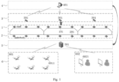
- roof air quality detection module 1 this module is composed of roof air quality detection devices 101 respectively arranged on the top of each compartment.
- Each roof air quality detection device 101 includes a CO 2 concentration sensor, a NO 2 concentration sensor, an SO 2 concentration sensor, a PM2.5 concentration sensor, a VOC sensor, and a dust sensor.
- Roof air quality detection devices 101 are respectively arranged at the head, middle part and tail of the roof of each compartment. The data acquired by the roof air quality detection module 1 is transmitted to the data processing module 4 by the data transmission module 3.
- Underbody air quality detection module 2 this module is composed of underbody air quality detection devices 201 respectively arranged on the bottom of each compartment.
- Each underbody air quality detection device 201 includes a CO 2 concentration sensor, a NO 2 concentration sensor, an SO 2 concentration sensor, a PM2.5 concentration sensor, a VOC sensor, and a dust sensor.
- Underbody air quality detection devices 201 are respectively arranged at the head, middle part and tail of the bottom of each compartment. The data acquired by the underbody air quality detection module 2 is transmitted to the data processing module 4 by the data transmission module 3.
- Data transmission module 3 the data transmission module 3 includes wireless transmission modules 301, and each compartment is equipped with a wireless transmission device to connect the roof air quality detection module 1, the underbody air quality detection module 2 and the data processing module 4 to store the acquired data and transmit data between different modules. Considering the length of the train, the data can be transmitted through a 4G network, which is economical and simple.
- Data processing module 4 a central computer 401 is equipped for every three compartments, which is defined as an air quality monitoring area and constitutes the data processing module 4. The central computer 401 is configured to receive acquired air data of key roof components and acquired air data of key underbody components acquired from three compartments within a monitoring range, perform data preprocessing and model training respectively, and output model training results in real time.
- Platform data center 5 this module includes a platform computer 501, which is configured to receive pollution condition level data of key components sent by the data processing module 4 of the train, select appropriate cleaning and protection methods according to different receiving results, and send protection instructions to a drone station on a platform 601 or a human-computer interaction terminal 602.
- Platform execution module 6 including the drone station on a platform 601 and the human-computer interaction terminal 602. Both the drone station on the platform 601 and the human-computer interaction terminal 602 are connected to the platform data center 5.
- Drone station on a platform 601 this module is composed of protective drones 6011, a wireless instruction transceiver, and a charging platform, wherein the wireless instruction transceiver is configured to receive protection instructions from the platform computer 501, and the charging platform is configured to charge the drones 6011.
- the wireless instruction transceiver and the charging platform are not shown in the drawings, but they do not affect the understanding and implementation of the present invention by those skilled in the art.
- the drones 6011 After receiving the protection instructions from the platform data center 5, the drones 6011 autonomously identify polluted key components (located on the roof or underbody), and perform light or deep cleaning. Each protective drone 6011 is equipped with a spraying and cleaning device and lighting equipment.
- Human-computer interaction terminal 602 this module includes an instruction receiving computer 6021, which is configured to receive manual maintenance instructions sent by the station data center 5 and display the same on an interactive interface.
- the entire method for protecting the operation of a train under an air pollution environment includes two processes: an off-line training process and an on-line protection process when the train stops.
- Off-line training process The method of the present invention first acquires air pollutant concentration information of a space where key roof and underbody components are located, and then sends the acquired data to the central computer 401 in a corresponding detection area for data preprocessing and model training.
- the training model includes two deep network models, which are configured to acquire pollution condition levels of key components according to the measured pollutant concentration. The entire off-line process is described as follows:
- Different pollutant concentration is acquired by the roof air quality detection device 101 and the underbody air quality detection device 201, wherein the acquired roof air quality detection data is expressed as [ t , I CO 2 ,I NO 2 , I SO 2 ,I pm 2.5 ,I voc ,I dust ], and the underbody air quality detection data is expressed as [t, O CO 2 ,O NO 2 , O SO 2 , O PM 2.5 ,O voc , O dust ].
- the data of the roof air quality detection device 101 and the underbody air quality detection device 201 is transmitted to the central computer 401 of the data processing module 4 via the wireless transmission module 301 for preprocessing the acquired data.
- the entire data preprocessing steps are as follows:
- Roof air quality data is measured under outdoor experimental conditions, 1000 groups of different degrees of roof air quality data are picked, then indoor simulation operation is performed on each group of experimental data among the 1000 groups under experimental simulation conditions to obtain pollution conditions of a pantograph under different conditions, and four pollution levels 0, 1, 2, and 3 are set according to the overall pollution condition.
- the calculation model of pollutant condition about roof component is trained using a long short term memory (LSTM) deep network.
- the input of the model training is average roof air quality detection data and key roof component pollutant exposure time [ I CO 2 average ,I NO 2 average , I SO 2 average , I pm 2.5 average , I voc average , I dust average , T 0 ], the output is the pollution condition levels 0, 1, 2, and 3 of the pantograph acquired under the simulated experimental conditions, thereby obtaining the calculation model of pollutant condition about roof component based on the LSTM deep network.
- the input layer of the LSTM deep network includes 7 nodes, the output layer includes 1 node, the maximum number of iterations in the training process is set to be 1200, and the learning rate in the training is 0.01.
- the weight and threshold of the LSTM deep network are obtained by optimization using quantum particle swarm with adaptive weights. The process is as follows:
- Underbody air quality data is measured under outdoor experimental conditions, 1000 groups of different degrees of underbody air quality data are picked, then indoor simulation operation is performed on each group of experimental data among the 1000 groups under experimental simulation conditions to obtain pollution conditions of a running portion under different conditions, and four pollution levels 0, 1, 2, and 3 are set according to the overall pollution condition.
- the calculation model of pollutant condition about underbody component is trained using a gated recurrent unit (GRU) deep network.
- the input of the model training is average underbody air quality detection data and key underbody component pollutant exposure time [ O CO 2 average , O NO 2 average , O SO 2 average, O pm 2.5 average , O voc average ,O dust average , T 1 ], the output is the pollution condition levels 0, 1, 2, and 3 of the running portion acquired under the simulated experimental conditions, thereby obtaining the calculation model of pollutant condition about underbody component based on the GRU deep network.
- the number of input layer nodes is 7
- the number of hidden layer nodes is 5
- the number of output layer nodes is 1
- the maximum number of iterations in the training process is set to be 800
- the learning rate in the training is 0.01
- the threshold is 0.06.
- the weight and threshold of the calculation model of pollutant condition about underbody component based on the GRU deep network are subjected to optimization selection through a chaotic bat algorithm.
- the process is as follows:
Landscapes
- Engineering & Computer Science (AREA)
- Life Sciences & Earth Sciences (AREA)
- Chemical & Material Sciences (AREA)
- Health & Medical Sciences (AREA)
- Physics & Mathematics (AREA)
- General Physics & Mathematics (AREA)
- General Health & Medical Sciences (AREA)
- Pathology (AREA)
- Immunology (AREA)
- Biochemistry (AREA)
- Analytical Chemistry (AREA)
- Biodiversity & Conservation Biology (AREA)
- Environmental Sciences (AREA)
- Environmental & Geological Engineering (AREA)
- Combustion & Propulsion (AREA)
- Ecology (AREA)
- Food Science & Technology (AREA)
- Medicinal Chemistry (AREA)
- Artificial Intelligence (AREA)
- Evolutionary Computation (AREA)
- Theoretical Computer Science (AREA)
- Data Mining & Analysis (AREA)
- Mechanical Engineering (AREA)
- Mathematical Physics (AREA)
- Bioinformatics & Cheminformatics (AREA)
- Bioinformatics & Computational Biology (AREA)
- Computer Vision & Pattern Recognition (AREA)
- General Engineering & Computer Science (AREA)
- Evolutionary Biology (AREA)
- Biomedical Technology (AREA)
- Electric Propulsion And Braking For Vehicles (AREA)
- Train Traffic Observation, Control, And Security (AREA)
- Management, Administration, Business Operations System, And Electronic Commerce (AREA)
Claims (11)
- Verfahren zum Schützen des Betriebs eines Zugs in einer Luftverschmutzungsumgebung, wobei das Verfahren die folgenden Schritte beinhaltet:Schritt 1: Erfassen mehrerer Gruppen von Dachluftqualität-Erkennungsdaten und Unterbodenluftqualität-Erkennungsdaten und Berechnen einer durchschnittlichen Konzentration jedes Schadstoffs auf dem Dach und am Unterboden des Zugs während einer Betriebszeit von der Zeit des Verlassens eines Abfahrtsbahnhofs bis zu einer aktuellen Zeit;Schritt 2: Lösen eines umfassenden Dachluftbewertungsindikators Q0 anhand der Dachluftqualität-Erkennungsdaten in Schritt 1 und Lösen eines umfassenden Unterbodenluftbewertungsindikators Q1 anhand der Unterbodenluftqualität-Erkennungsdaten in Schritt 1;Schritt 3: Berechnen einer Expositionszeit T0 von Dachkomponenten unter der Bedingung Q0 ≥Q und Berechnen einer Expositionszeit T1 von Unterbodenkomponenten unter der Bedingung Q1 ≥Q; wobei Q ein eingestellter Gesundheitswert des umfassenden Luftqualitätbewertungsindikators ist;Schritt 4: Trainieren eines Berechnungsmodells des Schadstoffzustands der Dachkomponente gemäß dem folgenden Verfahren:Simulieren des Betriebs des Zugs anhand der in Schritt 1 berechneten durchschnittlichen Konzentration jedes Schadstoffs auf dem Dach des Zugs während der Betriebszeit von der Zeit des Verlassens des Abfahrtsbahnhofs bis zur aktuellen Zeit und der in Schritt 3 entsprechend gelösten T0 als experimentelle Simulationsbedingungen, um eine Verschmutzungsstufe G0 der Dachkomponenten unter verschiedenen experimentellen Simulationsbedingungen zu erhalten, wobei der Verschmutzungsgrad der Dachkomponenten als G-Stufen klassifiziert wird; undTrainieren des Berechnungsmodells des Schadstoffzustands der Dachkomponente anhand der in Schritt 1 berechneten durchschnittlichen Konzentration jedes Schadstoffs auf dem Dach des Zugs während der Betriebszeit von der Zeit des Verlassens des Abfahrtsbahnhofs bis zur aktuellen Zeit und der in Schritt 3 entsprechend gelösten T0 als Eingabe und mit G0 als Ausgabe, um ein trainiertes Berechnungsmodell des Schadstoffzustands der Dachkomponente zu erhalten;Trainieren eines Berechnungsmodells des Schadstoffzustands der Unterbodenkomponente gemäß dem folgenden Verfahren:Simulieren des Betriebs des Zugs anhand der in Schritt 1 berechneten durchschnittlichen Konzentration jedes Schadstoffs am Unterboden des Zugs während der Betriebszeit von der Zeit des Verlassens des Abfahrtsbahnhofs bis zur aktuellen Zeit und der in Schritt 3 entsprechend gelösten T1 als experimentelle Simulationsbedingungen, um eine Verschmutzungsstufe G1 der Unterbodenkomponenten unter verschiedenen experimentellen Simulationsbedingungen zu erhalten, wobei der Verschmutzungsgrad der Unterbodenkomponenten als G-Stufen klassifiziert wird; undTrainieren des Berechnungsmodells des Schadstoffzustands der Unterbodenkomponente anhand der in Schritt 1 berechneten durchschnittlichen Konzentration jedes Schadstoffs am Unterboden des Zugs während der Betriebszeit von der Zeit des Verlassens des Abfahrtsbahnhofs bis zur aktuellen Zeit und der in Schritt 3 entsprechend gelösten T1 als Eingabe und mit G1 als Ausgabe, um ein trainiertes Berechnungsmodell des Schadstoffzustands der Unterbodenkomponente zu erhalten;Schritt 5: Erfassen, nach dem Anhalten des Zugs, von Dachluftqualität-Erkennungsdaten und Unterbodenluftqualität-Erkennungsdaten;Schritt 6: Lösen, anhand der Dachluftqualität-Erkennungsdaten in Schritt 5, einer durchschnittlichen Konzentration jedes Schadstoffs auf dem Dach des Zugs während der Betriebszeit von der Zeit des Verlassens des Abfahrtsbahnhofs bis zur aktuellen Zeit, eines umfassenden Dachluftbewertungsindikators Q0 und einer Expositionszeit T0 der Dachkomponenten unter der Bedingung Q0 ≥Q; und Aufrufen des trainierten Berechnungsmodells des Schadstoffzustands der Dachkomponente unter der Bedingung Q0 ≥Q, um eine Dachkomponentenverschmutzungsstufe zu lösen; und
Lösen, anhand der Unterbodenluftqualität-Erkennungsdaten in Schritt 5, einer durchschnittlichen Konzentration jedes Schadstoffs am Unterboden des Zugs während der Betriebszeit von der Zeit des Verlassens des Abfahrtsbahnhofs bis zur aktuellen Zeit, eines umfassenden Unterbodenluftbewertungsindikators Q1 und einer Expositionszeit T1 der Unterbodenkomponenten unter der Bedingung Q1 ≥Q; und Aufrufen des trainierten Berechnungsmodells des Schadstoffzustands der Unterbodenkomponente unter der Bedingung Q1 ≥Q, um eine Unterbodenkomponentenverschmutzungsstufe zu lösen; undSchritt 7: Durchführen einer entsprechenden Reinigung der Dachkomponenten gemäß der in Schritt 6 gelösten Verschmutzungsstufe der Dachkomponenten; und
Durchführen einer entsprechenden Reinigung der Unterbodenkomponenten gemäß der in Schritt 6 gelösten Verschmutzungsstufe der Unterbodenkomponenten. - Verfahren zum Schützen des Betriebs des Zugs in einer Luftverschmutzungsumgebung nach Anspruch 1, wobei die Dachluftqualität-Erkennungsdaten und die Unterbodenluftqualität-Erkennungsdaten jeweils eine oder mehrere von CO2-Konzentration, NO2-Konzentration, SO2-Konzentration, PM2,5-Konzentration, VOC-Konzentration und Staubkonzentration umfassen.
- Verfahren zum Schützen des Betriebs des Zugs in einer Luftverschmutzungsumgebung nach Anspruch 1, wobei die Dachluftqualität-Erkennungsdaten und/oder die Unterbodenluftqualität-Erkennungsdaten von mehreren Überwachungsstellen gewonnen werden.
- Verfahren zum Schützen des Betriebs des Zugs in einer Luftverschmutzungsumgebung nach Anspruch 1, wobei ein Berechnungsverfahren für den umfassenden Dachluftbewertungsindikators Q0 wie folgt lautet:
Q0 = Dach-CO2-Konzentration × p1 + Dach-NO2-Konzentration × p2 + Dach-SO2- Konzentration × p3 + Dach-PM2,5-Konzentration × p4 + Dach-VOC-Konzentration × p5 + Dach-Staubkonzentration × p6 ; wobei ein Berechnungsverfahren für den umfassenden Unterbodenluft-Bewertungsindikator Q1 wie folgt lautet:Q1 = Unterboden-Co2-Konzentration × p1 + Unterboden-NO2-Konzentration × p2 + Unterboden-SO2-Konzentration × p3 + Unterboden-PM2,5-Konzentration × p4 + Unterboden- VOC-Konzentration × p5 + Unterboden-Staubkonzentration × p6 ; wobei p1, p2 , p3, p4, p5 und p6 die entsprechenden Schadstoffgewichte sind. - Verfahren zum Schützen des Betriebs des Zugs in einer Luftverschmutzungsumgebung nach Anspruch 1, wobei in Schritt 4 das Berechnungsmodell des Verschmutzungszustands der Dachkomponente mit einem tiefen LSTM-(Long Short Term Memory)-Netzwerkalgorithmus trainiert wird, wobei Gewichtung und Schwelle des tiefen LSTM-Netzwerks durch Optimieren unter Verwendung eines Quantenpartikelschwarms mit adaptiven Gewichtungen erhalten werden, das Folgendes beinhaltet:Schritt A1: Verwenden eines Positionsvektors jedes Quantenpartikelindividuums in Quantenpartikelschwärmen als Gewichtung und Schwelle des tiefen LSTM-Netzwerks, und Initialisieren des Positionsvektorparameters des Quantenpartikelschwarmindividuums in eine Zufallszahl mit einem Bereich von [-1, 1];
wobei die Anzahl der Quantenpartikelschwärme in einem Bereich von [30, 100] liegt, die Anzahl der Partikel in einem Quantenpartikelschwarm in einem Bereich von [4, 60] liegt, die maximale Anzahl von Iterationen in einem Bereich von [300, 1200] liegt, die Anzahl von Iterationen zum Bilden eines Eliteschwarms in einem Bereich von [50, 200] liegt, die Schwelle für die Bestimmung von vorzeitiger Konvergenz in einem Bereich von [0,02, 0,5] liegt und das 6% Schlechteste-Partikel-Verhältnis δ% unter den Schwärmen in einem Bereich von [1%, 6%] liegt;Schritt A2: Einstellen einer Eignungsfunktion und Bestimmen eines Positionsvektors eines anfänglichen optimalen Quantenpartikelindividuums und der Anzahl von Iterationen t, t=l;
Einsetzen von Gewicht und Schwelle entsprechend dem Positionsvektor des Quantenpartikelindividuums in das Berechnungsmodell des Schadstoffzustands der Dachkomponente auf der Basis des tiefen LSTM-Netzwerks, Bestimmen des Typs eines Identifikationsvektoretiketts anhand des Berechnungsmodells des Schadstoffzustands der Dachkomponente auf der Basis des tiefen LSTM-Netzwerks, bestimmt aus dem Positionsvektor des Quantenpartikelindividuums, und Verwenden des Kehrwerts des mittleren quadratischen Fehlers des Ausgangsvektoretiketts und des tatsächlichen Vektoretiketts als eine zweite Eignungsfunktion;Schritt A3: Berechnen einer Kolonie-Eignungsvarianz jedes Quantenpartikelschwarms und Durchführen einer Bestimmung von vorzeitiger Konvergenz;
Mutieren, wenn die Kolonie-Eignungsvarianz des Quantenpartikelschwarms kleiner als eine Schwelle γ für die Bestimmung von vorzeitiger Konvergenz ist, von δ % der Partikel mit der schlechtesten Eignung und eines Kolonie-Extremwertpartikels in dem Quantenpartikelschwarm, und Verwenden des Partikels mit der besten Eignung aktuell als ein globales optimales Quantenpartikelindividuum;Schritt A4: Feststellen, ob ein Eliteschwarm gebildet werden soll;
Extrahieren, wenn die Anzahl der Iterationen größer ist als die Anzahl der Iterationen des Eliteschwarms, von Extremwerten verschiedener Schwärme durch Informationsaustausch zwischen den Schwärmen, um den Eliteschwarm zu bilden, und Springen zu Schritt A8, andernfalls Ausführen von Schritt A5;Schritt A5: Aktualisieren von Partikelparametern der verschiedenen Schwärme;Schritt A6: Neuberechnen, für jedes Partikel, des Eignungswerts des Partikels und Vergleichen des Eignungswerts des Partikels mit dem aktuellen individuellen Extremwert des Partikels, wenn der Eignungswert des Partikels besser ist als der aktuelle individuelle Extremwert des Partikels, Aktualisieren des individuellen Extremwerts des Partikels, Vergleichen eines aktuellen Kolonie-Extremwerts des globalen Extremwertpartikels mit dem Eignungswert jedes Partikels, wenn der Eignungswert eines Partikels besser ist als der aktuelle Kolonie-Extremwert, Aktualisieren des globalen Extremwertpartikels, unter der Annahme t=t+1, und Ausführen von Schritt A3;Schritt A7: Fortsetzen der Entwicklung des Eliteschwarms;Schritt A8: Feststellen, ob die maximale Anzahl von Iterationen erfüllt ist, und Beenden des Prozesses, wenn die maximale Anzahl von Iterationen erfüllt ist, andernfalls Annehmen von t=t+I und Ausführen von Schritt B3, bis der globale Optimalwert gefunden ist; und Ausgeben von Gewichtung und Schwelle des tiefen LSTM-Netzwerks. - Verfahren zum Schützen des Betriebs des Zugs in einer Luftverschmutzungsumgebung nach Anspruch 1, wobei in Schritt 4 das Berechnungsmodell des Schadstoffzustands der Unterbodenkomponente mit einem tiefen GRU-(Gated Recurrent Unit)-Networkalgorithmus trainiert wird, wobei Gewichtung und Schwelle des tiefen GRU-Networks durch Optimieren mittels eines chaotischen Fledermaus-Algorithmus erhalten werden, das Folgendes beinhaltet:Schritt B1: Verwenden der Position eines Fledermausindividuums als Gewichtung und Schwelle des Berechnungsmodells des Schadstoffzustands der Unterbodenkomponente auf der Basis des tiefen GRU-Netzwerks, Initialisieren von Fledermausschwärmen und Einstellen von Parametern der Fledermausschwärme; wobei die Größe eines Fledermausschwarms in einem Bereich von [300, 600] liegt, die maximale Pulsfrequenz r0 des Fledermausindividuums in einem Bereich von [0,3, 0,6] liegt, die maximale Impulsschallintensität A0 in einem Bereich von [0,3, 0,6] liegt, die maximale Anzahl von Iterationen in einem Bereich von [200, 500] liegt, die Suchgenauigkeit in einem Bereich von [0,002, 0,2] liegt, die Impulsfrequenz in einem Bereich von [0, 1,8] liegt, der erhöhte Koeffizient der Fledermaussuchfrequenz in einem Bereich von [0,04, 0,1] liegt, der Schallintensitätsdämpfungskoeffizient in einem Bereich von [0,75, 0,1] liegt, die maximale Anzahl der Iterationen in einem Bereich von [200, 800] und die maximale Suchgenauigkeit in einem Bereich von [0,02, 0,15] liegt;Schritt B2: Einstellen einer Eignungsfunktion und Bestimmen einer Position eines anfänglichen optimalen Fledermausindividuums und der Anzahl der Iterationen t, t=1;Einsetzen von Gewichtung und Schwelle entsprechend der Position des Fledermausindividuums in das Berechnungsmodell des Schadstoffzustands der Unterbodenkomponente auf der Basis des tiefen GRU-Netzwerks, Erhalten eines Erkennungsergebnisses anhand des Berechnungsmodells des Schadstoffzustands der Unterbodenkomponente auf der Basis des tiefen GRU-Netzwerks, bestimmt aus der Position des Fledermausindividuums, und Konstruieren einer ersten Eignungsfunktion f1(x) aus der Differenz E zwischen dem Erkennungsergebnis und der tatsächlichen Situation, f1(x)=1/(E+l);Berechnen der Eignung der Position jedes Fledermausindividuums anhand der ersten Eignungsfunktion und Verwenden der Position des Fledermausindividuums entsprechend der maximalen Eignung als Position des anfänglichen optimalen Fledermausindividuums;Schritt B3: Aktualisieren von Geschwindigkeit und Position des Fledermausindividuums anhand einer festgelegten Impulsfrequenz;Schritt B4: wenn Rand 1 >ri, zufälliges Stören der Fledermaus an der optimalen individuellen Position, um eine gestörte Position des Fledermausindividuums zu erzeugen;
wobei Rand1 eine Zufallszahl ist, die gleichmäßig auf [0, l] verteilt ist, und ri eine Impulsfrequenz der i-ten Fledermaus ist;Schritt B5: wenn Rand2>Ai und die Eignung der gestörten Position des Fledermausindividuums besser ist als die Eignung der Position des Fledermausindividuums vor der Störung, Bewegen des Fledermausindividuums zu der gestörten Position oder andernfalls Beibehalten des Fledermausindividuums an der ursprünglichen Position;
wobei Rand2 eine Zufallszahl ist, die gleichmäßig auf [0, l] verteilt ist, und Ai eine Schallintensität der i-ten Fledermaus ist;Schritt B6: Aktualisieren, wenn die Bedingung von Schritt BS erfüllt ist, der Impulsfrequenz und der Impulsschallintensität des Fledermausindividuums anhand des erhöhten Koeffizienten der Fledermaussuchfrequenz und des Schallintensitätsabschwächungskoeffizienten, und Springen zu Schritt B4, oder andernfalls Springen zu Schritt B7;Schritt B7: Berechnen der Eignung der Position jedes Fledermausindividuums in dem aktuellen Fledermausschwarm und Durchführen einer chaotischen Optimierung von Position und Geschwindigkeit an den obersten m% Fledermausindividuen in absteigender Reihenfolge, um aktualisierte oberste m% Fledermausindividuen zu erhalten, wobei m in einem Bereich von [4, 25] liegt; undSchritt B8: Feststellen, ob die maximale Anzahl von Iterationen oder die maximale Suchgenauigkeit erreicht ist; wenn sie erreicht ist, Auswählen eines globalen optimalen Fledermausindividuums aus den aktualisierten obersten m% Fledermausindividuen gemäß dem Eignungswert und Ausgeben der optimalen Gewichtung und Schwelle des Berechnungsmodells des Schadstoffzustands der Unterbodenkomponente auf der Basis des tiefen GRU-Netzwerks entsprechend dem globalen optimalen Fledermausindividuum; andernfalls Annehmen von t=t+1 und Ausführen von Schritt B3, um mit der nächsten Iteration fortzufahren. - System zum Schützen des Betriebs des Zugs in einer Luftverschmutzungsumgebung, das Folgendes umfasst:ein Dachluftqualität-Erkennungsmodul (1), konfiguriert zum Erfassen von Dachluftqualitäts-Erkennungsdaten;ein Unterbodenluftqualität-Erkennungsmodul (2), konfiguriert zum Erfassen von Unterbodenluftqualität-Erkennungsdaten;ein Datenübertragungsmodul (3), konfiguriert zum Übertragen der erfassten Dachluftqualität-Erkennungsdaten und Unterbodenluftqualität-Erkennungsdaten zu einem Datenverarbeitungsmodul (4);das Datenverarbeitungsmodul (4), konfiguriert zum Modellieren und Berechnen von Verschmutzungsstufen; wobei:
der Modellierungsprozess Folgendes beinhaltet:Berechnen einer durchschnittlichen Konzentration jedes Schadstoffs auf dem Dach des Zugs während einer Betriebszeit von der Zeit des Verlassens eines Abfahrtsbahnhofs bis zu einer aktuellen Zeit anhand der Dachluftqualität-Erkennungsdaten, und Berechnen einer durchschnittlichen Konzentration jedes Schadstoffs am Unterboden des Zugs während der Betriebszeit von der Zeit des Verlassens des Abfahrtsbahnhofs bis zur aktuellen Zeit anhand der Unterbodenluftqualität-Erkennungsdaten;Lösen eines umfassenden Dachluftbewertungsindikators Q0 anhand der Dachluftqualität-Erkennungsdaten, und Lösen eines umfassenden Unterbodenluftbewertungsindikators Q1 anhand der Unterbodenluftqualität-Erkennungsdaten;Berechnen einer Expositionszeit T0 von Dachkomponenten unter der Bedingung Q 0≥Q und Berechnen einer Expositionszeit T1 von Unterbodenkomponenten unter der Bedingung Q1 ≥Q; wobei Q ein eingestellter Gesundheitswert eines umfassenden Luftqualitätsbewertungsindikators ist;Trainieren eines Berechnungsmodells des Schadstoffzustands der Dachkomponente gemäß dem folgenden Prozess:Simulieren des Betriebs des Zugs anhand der berechneten durchschnittlichen Konzentration jedes Schadstoffs auf dem Dach des Zuges während einer Betriebszeit von der Zeit des Verlassens eines Abfahrtsbahnhofs bis zu einer aktuellen Zeit und der entsprechend gelösten T0 als experimentelle Simulationsbedingungen, um eine Verschmutzungsstufe G0 der Dachkomponenten unter verschiedenen experimentellen Simulationsbedingungen zu erhalten, wobei der Verschmutzungsgrad der Dachkomponenten als G-Stufen klassifiziert wird; undTrainieren des Berechnungsmodells des Schadstoffzustands der Dachkomponente anhand der berechneten durchschnittlichen Konzentration jedes Schadstoffs auf dem Dach des Zugs während der Betriebszeit von der Zeit des Verlassens des Abfahrtsbahnhofs bis zur aktuellen Zeit und der entsprechend gelösten T0 als Eingabe und mit G0 als Ausgabe, um ein trainiertes Berechnungsmodell des Schadstoffzustands der Dachkomponente zu erhalten;Trainieren eines Berechnungsmodells des Schadstoffzustands der Unterbodenkomponente gemäß dem folgenden Prozess:Simulieren des Betriebs des Zugs anhand der berechneten durchschnittlichen Konzentration jedes Schadstoffs am Unterboden des Zugs während der Betriebszeit von der Zeit des Verlassens des Abfahrtsbahnhofs bis zur aktuellen Zeit und der entsprechend gelösten T1 als experimentelle Simulationsbedingungen, um eine Verschmutzungsstufe G1 der Unterbodenkomponenten unter verschiedenen experimentellen Simulationsbedingungen zu erhalten, wobei der Verschmutzungsgrad der Unterbodenkomponenten als G-Stufen klassifiziert wird; undTrainieren des Berechnungsmodells des Schadstoffzustands der Unterbodenkomponente anhand der berechneten durchschnittlichen Konzentration jedes Schadstoffs am Unterboden des Zugs während der Betriebszeit von der Zeit des Verlassens des Abfahrtsbahnhofs bis zur aktuellen Zeit und der entsprechend gelösten T1 als Eingabe und mit G1 als Ausgabe, um ein trainiertes Berechnungsmodell des Schadstoffzustands der Unterbodenkomponente zu erhalten;wobei der Prozess des Berechnens von Verschmutzungsstufen Folgendes beinhaltet:Erfassen, nach dem Anhalten des Zugs, von Dachluftqualität-Erkennungsdaten und Unterbodenluftqualität-Erkennungsdaten;Lösen, anhand der Dachluftqualität-Erkennungsdaten, einer durchschnittlichen Konzentration jedes Schadstoffs auf dem Dach des Zugs während der Betriebszeit von der Zeit des Verlassens des Abfahrtsbahnhofs bis zur aktuellen Zeit, eines umfassenden Dachluftbewertungsindikators Q0 und einer Expositionszeit T0 der Dachkomponenten unter der Bedingung Q0 ≥Q; und Aufrufen des trainierten Berechnungsmodells des Schadstoffzustands der Dachkomponente unter der Bedingung Q0 ≥Q, um eine Dachkomponentenverschmutzungsstufe zu lösen;Lösen, anhand der Unterbodenluftqualität-Erkennungsdaten in Schritt 5, einer durchschnittlichen Konzentration jedes Schadstoffs am Unterboden des Zugs während der Betriebszeit von der Zeit des Verlassens des Abfahrtsbahnhofs bis zur aktuellen Zeit, eines umfassenden Unterbodenluftbewertungsindikators Q1 und einer Expositionszeit T1 der Unterbodenkomponenten unter der Bedingung Q1 ≥Q; und Aufrufen des trainierten Berechnungsmodells des Schadstoffzustands der Unterbodenkomponente unter der Bedingung Q1 ≥Q, um eine Unterbodenkomponenten-Verschmutzungsstufe zu lösen;Senden der Dachkomponentenverschmutzungsstufe und der Unterbodenkomponentenverschmutzungsstufe zu einem Bahnsteigdatenzentrum (5);das Bahnsteigdatenzentrum (5), konfiguriert zum Empfangen der vom Datenverarbeitungsmodul (4) gesendeten Dachkomponentenverschmutzungsstufe und Unterbodenkomponentenverschmutzungsstufe, und Senden von Schutzanweisungen zu einem Bahnsteigausführungsmodul (6) gemäß der empfangenen Dachkomponentenverschmutzungsstufe und Unterbodenkomponentenverschmutzungsstufe; unddas Bahnsteigausführungsmodul (6), konfiguriert zum Durchführen der entsprechenden Reinigung der Dachkomponenten und/oder der Unterbodenkomponenten gemäß den vom Bahnsteigdatenzentrum (5) gesendeten Schutzanweisungen. - System zum Schützen des Betriebs des Zugs in einer Luftverschmutzungsumgebung nach Anspruch 7, wobei sowohl das Dachluftqualität-Erkennungsmodul (1) als auch das Unterbodenluftqualität-Erkennungsmodul (2) eines oder mehrere von einem CO2-Konzentrationssensor, einem NO2-Konzentrationssensor, einem SO2-Konzentrationssensor, einem PM2,5-Konzentrationssensor, einem VOC-Konzentrationssensor und einem Staubkonzentrationssensor umfassen.
- System zum Schützen des Betriebs des Zugs in einer Luftverschmutzungsumgebung nach Anspruch 7, wobei das Dachluftqualität-Erkennungsmodul (1) eine oder mehrere Dachluftqualität-Erkennungsvorrichtungen (101) umfasst und eine Dachluftqualität-Erkennungsvorrichtung (101) im vorderen Teil, im mittleren Teil bzw. im hinteren Teil jedes Abteils angeordnet ist;
das Unterbodenluftqualität-Erkennungsmodul (2) eine oder mehrere Unterbodenluftqualität-Erkennungsvorrichtungen (201) umfasst, und eine Unterbodenluftqualität-Erkennungsvorrichtung (201) jeweils im vorderen Teil, im mittleren Teil bzw. im hinteren Teil jedes Abteils angeordnet ist; und alle drei Abteile ein Datenverarbeitungsmodul (4) gemeinsam nutzen. - System zum Schützen des Betriebs des Zugs in einer Luftverschmutzungsumgebung nach Anspruch 7, wobei das Bahnsteigausführungsmodul (6) eine Drohnenstation auf einem Bahnsteig (601) und ein Mensch-Computer-Interaktionsterminal (602) umfasst, wobei sowohl die Drohnenstation auf dem Bahnsteig (601) als auch das Mensch-Computer-Interaktionsterminal (602) mit dem Bahnsteigdatenzentrum (5) verbunden sind; die Drohnenstation auf dem Bahnsteig eine oder mehrere Drohnen (6011) umfasst, und jede Drohne (6011) mit einer Sprüh- und Reinigungsvorrichtung und mit Beleuchtungsausrüstung ausgestattet ist, und das Mensch-Computer-Interaktionsterminal (602) einen Befehlsempfangscomputer (6021) umfasst.
- Verfahren zum Lösen einer Dachkomponentenverschmutzungsstufe und einer Unterbodenkomponentenverschmutzungsstufe eines Zugs in einer Luftverschmutzungsumgebung, wobei das Verfahren die folgenden Schritte beinhaltet:Schritt 1: Erfassen mehrerer Gruppen von Dachluftqualität-Erkennungsdaten und Unterbodenluftqualität-Erkennungsdaten und Berechnen einer durchschnittlichen Konzentration jedes Schadstoffs auf dem Dach und am Unterboden des Zugs während einer Betriebszeit von der Zeit des Verlassens eines Abfahrtsbahnhofs bis zu einer aktuellen Zeit;Schritt 2: Lösen eines umfassenden Dachluftbewertungsindikators Q0 anhand der Dachluftqualität-Erkennungsdaten in Schritt 1 und Lösen eines umfassenden Unterbodenluftbewertungsindikators Q1 anhand der Unterbodenluftqualität-Erkennungsdaten in Schritt 1;Schritt 3: Berechnen einer Expositionszeit T0 von Dachkomponenten unter der Bedingung Q0 ≥Q und Berechnen einer Expositionszeit T1 von Unterbodenkomponenten unter der Bedingung Q1 ≥Q; wobei Q ein eingestellter Gesundheitswert des umfassenden Luftqualitätbewertungsindikators ist;Schritt 4: Trainieren eines Berechnungsmodells des Schadstoffzustands der Dachkomponente gemäß dem folgenden Verfahren:Simulieren des Betriebs des Zugs anhand der in Schritt 1 berechneten durchschnittlichen Konzentration jedes Schadstoffs auf dem Dach des Zugs während der Betriebszeit von der Zeit des Verlassens des Abfahrtsbahnhofs bis zur aktuellen Zeit und der in Schritt 3 entsprechend gelösten T0 als experimentelle Simulationsbedingungen, um eine Verschmutzungsstufe G0 der Dachkomponenten unter verschiedenen experimentellen Simulationsbedingungen zu erhalten, wobei der Verschmutzungsgrad der Dachkomponenten als G-Stufen klassifiziert wird; undTrainieren des Berechnungsmodells des Schadstoffzustands der Dachkomponente anhand der in Schritt 1 berechneten durchschnittlichen Konzentration jedes Schadstoffs auf dem Dach des Zugs während der Betriebszeit von der Zeit des Verlassens des Abfahrtsbahnhofs bis zur aktuellen Zeit und der in Schritt 3 entsprechend gelösten T0 als Eingabe und mit G0 als Ausgabe, um ein trainiertes Berechnungsmodell des Schadstoffzustands der Dachkomponente zu erhalten;Trainieren eines Berechnungsmodells des Schadstoffzustands der Unterbodenkomponente gemäß dem folgenden Verfahren:Simulieren des Betriebs des Zugs anhand der in Schritt 1 berechneten durchschnittlichen Konzentration jedes Schadstoffs am Unterboden des Zugs während der Betriebszeit von der Zeit des Verlassens des Abfahrtsbahnhofs bis zur aktuellen Zeit und der in Schritt 3 entsprechend gelösten T1 als experimentelle Simulationsbedingungen, um eine Verschmutzungsstufe G1 der Unterbodenkomponenten unter verschiedenen experimentellen Simulationsbedingungen zu erhalten, wobei der Verschmutzungsgrad der Unterbodenkomponenten als G-Stufen klassifiziert wird; undTrainieren des Berechnungsmodells des Schadstoffzustands der Unterbodenkomponente anhand der in Schritt 1 berechneten durchschnittlichen Konzentration jedes Schadstoffs am Unterboden des Zugs während der Betriebszeit von der Zeit des Verlassens des Abfahrtsbahnhofs bis zur aktuellen Zeit und der in Schritt 3 entsprechend gelösten T1 als Eingabe und mit G1 als Ausgabe, um ein trainiertes Berechnungsmodell des Schadstoffzustands der Unterbodenkomponente zu erhalten;Schritt 5: Erfassen, nach dem Anhalten des Zugs, von Dachluftqualität-Erkennungsdaten und Unterbodenluftqualität-Erkennungsdaten;Schritt 6: Lösen, anhand der Dachluftqualität-Erkennungsdaten in Schritt 5, einer durchschnittlichen Konzentration jedes Schadstoffs auf dem Dach des Zugs während der Betriebszeit von der Zeit des Verlassens des Abfahrtsbahnhofs bis zur aktuellen Zeit, eines umfassenden Dachluftbewertungsindikators Q0 und einer Expositionszeit T0 der Dachkomponenten unter der Bedingung Q0 ≥Q; und Aufrufen des trainierten Berechnungsmodells des Schadstoffzustands der Dachkomponente unter der Bedingung Q0 ≥Q, um eine Dachkomponentenverschmutzungsstufe zu lösen; und
Lösen, anhand der Unterbodenluftqualität-Erkennungsdaten in Schritt 5, einer durchschnittlichen Konzentration jedes Schadstoffs am Unterboden des Zugs während der Betriebszeit von der Zeit des Verlassens des Abfahrtsbahnhofs bis zur aktuellen Zeit, eines umfassenden Unterbodenluftbewertungsindikators Q1 und einer Expositionszeit T1 der Unterbodenkomponenten unter der Bedingung Q1 ≥Q; und Aufrufen des trainierten Berechnungsmodells des Schadstoffzustands der Unterbodenkomponente unter der Bedingung Q1 ≥Q, um eine Unterbodenkomponentenverschmutzungsstufe zu lösen.
Applications Claiming Priority (2)
| Application Number | Priority Date | Filing Date | Title |
|---|---|---|---|
| CN201910709594.6A CN110333325B (zh) | 2019-08-02 | 2019-08-02 | 一种大气污染环境下列车运行防护方法及系统 |
| PCT/CN2020/105470 WO2021023074A1 (zh) | 2019-08-02 | 2020-07-29 | 一种大气污染环境下列车运行防护方法及系统 |
Publications (4)
| Publication Number | Publication Date |
|---|---|
| EP3974826A1 EP3974826A1 (de) | 2022-03-30 |
| EP3974826A4 EP3974826A4 (de) | 2023-08-30 |
| EP3974826C0 EP3974826C0 (de) | 2024-07-24 |
| EP3974826B1 true EP3974826B1 (de) | 2024-07-24 |
Family
ID=68148433
Family Applications (1)
| Application Number | Title | Priority Date | Filing Date |
|---|---|---|---|
| EP20850716.0A Active EP3974826B1 (de) | 2019-08-02 | 2020-07-29 | Verfahren und system zum schutz eines zugbetriebs in einer umgebung mit luftverschmutzung |
Country Status (7)
| Country | Link |
|---|---|
| US (1) | US11932209B2 (de) |
| EP (1) | EP3974826B1 (de) |
| JP (1) | JP7142980B2 (de) |
| CN (1) | CN110333325B (de) |
| RU (1) | RU2771514C1 (de) |
| SG (1) | SG11202104219TA (de) |
| WO (1) | WO2021023074A1 (de) |
Families Citing this family (12)
| Publication number | Priority date | Publication date | Assignee | Title |
|---|---|---|---|---|
| CN108694356B (zh) * | 2017-04-10 | 2024-05-07 | 京东方科技集团股份有限公司 | 行人检测装置及方法、辅助驾驶系统 |
| CN110333325B (zh) * | 2019-08-02 | 2021-09-17 | 中南大学 | 一种大气污染环境下列车运行防护方法及系统 |
| CN112680501B (zh) * | 2020-12-30 | 2023-02-24 | 中南大学 | 基于微生物的列车车厢空气调控方法、系统及存储介质 |
| CN113283720A (zh) * | 2021-05-12 | 2021-08-20 | 中国环境科学研究院 | 用于确定尿素添加点尿素质量的方法、设备和存储介质 |
| CN113919235B (zh) * | 2021-10-29 | 2024-06-21 | 合肥综合性国家科学中心人工智能研究院(安徽省人工智能实验室) | 基于lstm演化聚类的移动源污染异常排放检测方法及介质 |
| CN114841469B (zh) * | 2022-06-14 | 2024-12-27 | 中国水利水电科学研究院 | 一种基于源流达模型的水质变化趋势预测系统及方法 |
| EP4324718A3 (de) * | 2022-08-18 | 2024-03-13 | ALSTOM Holdings | System und verfahren zum sammeln und überwachen von partikelmaterial, das von schienenfahrzeugen während der bewegung entlang von eisenbahnschienen erzeugt wird |
| CN115796034B (zh) * | 2022-12-01 | 2024-01-30 | 信阳师范学院 | 基于机器学习和数值模式的道路扬尘贡献评估系统和方法 |
| CN116703679A (zh) * | 2023-06-21 | 2023-09-05 | 北京市生态环境保护科学研究院 | 一种用于工业企业和工业园区的环保管理系统及管理方法 |
| CN116822970B (zh) * | 2023-08-30 | 2023-11-21 | 湖北省生态环境科学研究院(省生态环境工程评估中心) | 高环境健康风险污染物监管优先级的自动判断方法及系统 |
| CN118966887B (zh) * | 2024-07-30 | 2025-05-16 | 山东省热电设计院 | 一种基于大数据平台的能耗指标确定方法 |
| CN119272137B (zh) * | 2024-12-10 | 2025-03-14 | 浙江泓泰汽车配件有限公司 | 一种马达外壳用治具的寿命检测方法、存储介质及执行设备 |
Family Cites Families (52)
| Publication number | Priority date | Publication date | Assignee | Title |
|---|---|---|---|---|
| JP2000193651A (ja) * | 1998-12-24 | 2000-07-14 | Nippon Telegr & Teleph Corp <Ntt> | 環境モニタリング装置 |
| JP2006127100A (ja) * | 2004-10-28 | 2006-05-18 | Japan Radio Co Ltd | 環境監視支援システム |
| KR100797057B1 (ko) * | 2006-09-01 | 2008-01-22 | 한국철도기술연구원 | 미세 물입자와 에어커튼을 이용한 지하철 터널용 먼지 저감장치 |
| KR20090053028A (ko) * | 2007-11-22 | 2009-05-27 | 그린비환경기술연구소 주식회사 | 지하철 모니터링 시스템 |
| CN101604418A (zh) * | 2009-06-29 | 2009-12-16 | 浙江工业大学 | 基于量子粒子群算法的化工企业智能生产计划控制系统 |
| US8588999B2 (en) * | 2010-07-22 | 2013-11-19 | General Electric Company | Method and system for engine emission control |
| US9058560B2 (en) * | 2011-02-17 | 2015-06-16 | Superior Edge, Inc. | Methods, apparatus and systems for generating, updating and executing an invasive species control plan |
| UA63467U (ru) * | 2011-03-14 | 2011-10-10 | Кировоградский Национальный Технический Университет | Способ контроля загрязнения поверхности изоляторов под рабочим напряжением и замыкания фазы на землю |
| KR101278799B1 (ko) * | 2011-03-25 | 2013-06-25 | 주식회사 에코마이스터 | 철도차량 하부 세척장치 |
| CN202471872U (zh) * | 2011-11-28 | 2012-10-03 | 四川省电力公司超高压运行检修公司 | 输电线路绝缘子污秽在线监测系统 |
| CN202461068U (zh) * | 2012-01-10 | 2012-10-03 | 郭宝林 | 一种铁路罐车内壁清洗设备 |
| CN102622519B (zh) * | 2012-03-09 | 2015-01-07 | 北京交通大学 | 一种轨道不平顺幅值安全域估计方法 |
| CN102854191B (zh) * | 2012-07-18 | 2014-09-10 | 湖南大学 | 高速铁轨表面缺陷的实时视觉检测与识别方法 |
| CN102903113A (zh) * | 2012-10-08 | 2013-01-30 | 南京邮电大学 | 基于协作量子粒子群算法的多阈值图像分割方法 |
| US10058290B1 (en) * | 2013-06-21 | 2018-08-28 | Fitbit, Inc. | Monitoring device with voice interaction |
| US20150153317A1 (en) * | 2013-11-19 | 2015-06-04 | Acculation, Inc. | System for Inexpensive Characterization of Air Pollutants and Inexpensive Reduction of Indoor Dust |
| US20160091474A1 (en) * | 2014-09-29 | 2016-03-31 | Tanguy Griffon | Method and a System for Determining at Least One Forecasted Air Quality Health Effect Caused in a Determined Geographical Area by at Least One Air Pollutant |
| CN104297117A (zh) * | 2014-10-23 | 2015-01-21 | 浙江省环境保护科学设计研究院 | 基于遥感技术的风景名胜区道路交通污染预警装置及方法 |
| CN204228897U (zh) * | 2014-11-21 | 2015-03-25 | 西安伯龙高铁电气有限公司 | 列车绝缘检测系统 |
| DE102014226358B4 (de) * | 2014-12-18 | 2019-04-11 | Bayerische Motoren Werke Aktiengesellschaft | Vorrichtung und Verfahren zum Ermitteln einer Oberflächenverschmutzung eines Fahrzeugs |
| US20160245784A1 (en) * | 2015-02-23 | 2016-08-25 | Alen Corporation | Air quality sensing module and algorithm |
| US9719972B2 (en) * | 2015-03-31 | 2017-08-01 | International Business Machines Corporation | System and method for air-pollutant source-localization using parked motor vehicles |
| CN105136993A (zh) * | 2015-09-24 | 2015-12-09 | 浙江吉利控股集团有限公司 | 一种基于车联网的空气质量检测系统 |
| CN105335828A (zh) * | 2015-11-20 | 2016-02-17 | 中山领创网络科技有限公司 | 一种生产管理的操作方法 |
| CN105655067B (zh) * | 2015-12-28 | 2017-06-06 | 西南交通大学 | 动车组车顶绝缘子闪络电弧的在线防护装置及防护方法 |
| CN106129889A (zh) * | 2016-06-08 | 2016-11-16 | 徐洪军 | 一种绝缘子污秽在线监测装置以及绝缘子除污装置 |
| CN106127747B (zh) * | 2016-06-17 | 2018-10-16 | 史方 | 基于深度学习的汽车表面损伤分类方法及装置 |
| CN106226181A (zh) * | 2016-07-05 | 2016-12-14 | 保定华月胶带有限公司 | 检测高温高湿条件下硫化橡胶磨损的实验方法及设备 |
| CN106651100B (zh) * | 2016-10-12 | 2020-09-22 | 华南理工大学 | 基于车联网优选车载监测点的空气质量评估系统及方法 |
| CN106778838A (zh) * | 2016-11-29 | 2017-05-31 | 北京科技大学 | 一种预测空气质量的方法 |
| CN107085763A (zh) * | 2017-03-31 | 2017-08-22 | 无锡开放大学 | 一种电动汽车用驱动电机系统性能评价方法 |
| CN106960285B (zh) * | 2017-04-01 | 2021-01-08 | 北京交通大学 | 一种地铁列车运行服务质量检测装置及方法 |
| US10332320B2 (en) * | 2017-04-17 | 2019-06-25 | Intel Corporation | Autonomous vehicle advanced sensing and response |
| CN107167178B (zh) * | 2017-05-18 | 2019-07-05 | 重庆大学 | 车内环境检测方法及检测系统 |
| CN107316064B (zh) * | 2017-06-26 | 2020-07-14 | 长安大学 | 一种基于卷积神经网络的沥青路面裂缝分类识别方法 |
| CN107219157A (zh) * | 2017-07-29 | 2017-09-29 | 山东诺方电子科技有限公司 | 一种利用社会车辆进行大气颗粒物监测系统 |
| KR20250108756A (ko) * | 2017-08-02 | 2025-07-15 | 스트롱 포스 아이오티 포트폴리오 2016, 엘엘씨 | 대규모 데이터 세트들을 갖는 산업 사물 인터넷 데이터 수집 환경에서의 검출을 위한 방법들 및 시스템들 |
| US10890343B2 (en) * | 2018-02-07 | 2021-01-12 | Government Of The United States As Represented By The Administrator Of The U.S. Environmental Protection Agency | System and method for assessment and management of air pollution exposures using personal devices |
| JP6666376B2 (ja) * | 2018-03-26 | 2020-03-13 | 本田技研工業株式会社 | 車両浄化装置、車両浄化方法、及びプログラム |
| CN108537383A (zh) * | 2018-04-09 | 2018-09-14 | 山东建筑大学 | 一种基于模型融合的室内空气预测方法 |
| CN108572648B (zh) * | 2018-04-24 | 2020-08-25 | 中南大学 | 一种无人驾驶车辆电源多源融合预测方法及系统 |
| CN108508372B (zh) * | 2018-04-24 | 2019-09-03 | 中南大学 | 一种基于环境视觉融合的无人驾驶电量计算和预警方法与系统 |
| CN108845076A (zh) * | 2018-04-25 | 2018-11-20 | 北京市电话工程有限公司 | 一种小区的空气质量监测系统 |
| CN208476818U (zh) * | 2018-07-27 | 2019-02-05 | 沃尔新(北京)自动设备有限公司 | 轨道交通机车车辆的污染度检测系统及洗车系统 |
| CN109653046A (zh) * | 2018-12-07 | 2019-04-19 | 赵跃 | 一种城市道路公共交通立体化运行系统 |
| US10618002B2 (en) * | 2018-12-20 | 2020-04-14 | Tenneco Automotive Operating Company Inc. | System and method for treating ambient air |
| CN109726802B (zh) * | 2018-12-29 | 2020-11-20 | 中南大学 | 一种铁路和风电场环境风速机器学习预测方法 |
| CN110027413A (zh) * | 2019-02-19 | 2019-07-19 | 镇江帝研新技术研发有限公司 | 一种汽车悬浮通行装置、城市轨道交通系统及城间轨道交通网络 |
| DE102019207862A1 (de) * | 2019-05-28 | 2020-12-03 | Volkswagen Aktiengesellschaft | Servicestation zur Identifikation einer Verschmutzung einer Fahrzeugkomponente und Verfahren zum Betrieb der Servicestation |
| CN110239577B (zh) * | 2019-07-25 | 2020-06-30 | 中南大学 | 一种车内污染环境下列车乘员健康防护系统及其方法 |
| CN110333325B (zh) * | 2019-08-02 | 2021-09-17 | 中南大学 | 一种大气污染环境下列车运行防护方法及系统 |
| CN110395286B (zh) * | 2019-08-02 | 2020-08-07 | 中南大学 | 一种列车车内空气品质监测与通风调控方法、系统 |
-
2019
- 2019-08-02 CN CN201910709594.6A patent/CN110333325B/zh active Active
-
2020
- 2020-07-29 WO PCT/CN2020/105470 patent/WO2021023074A1/zh not_active Ceased
- 2020-07-29 RU RU2021121405A patent/RU2771514C1/ru active
- 2020-07-29 EP EP20850716.0A patent/EP3974826B1/de active Active
- 2020-07-29 JP JP2021541632A patent/JP7142980B2/ja active Active
- 2020-07-29 US US17/311,992 patent/US11932209B2/en active Active
- 2020-07-29 SG SG11202104219TA patent/SG11202104219TA/en unknown
Also Published As
| Publication number | Publication date |
|---|---|
| US20220153236A1 (en) | 2022-05-19 |
| EP3974826C0 (de) | 2024-07-24 |
| US11932209B2 (en) | 2024-03-19 |
| WO2021023074A1 (zh) | 2021-02-11 |
| CN110333325B (zh) | 2021-09-17 |
| JP7142980B2 (ja) | 2022-09-28 |
| EP3974826A4 (de) | 2023-08-30 |
| EP3974826A1 (de) | 2022-03-30 |
| RU2771514C1 (ru) | 2022-05-05 |
| CN110333325A (zh) | 2019-10-15 |
| JP2022518471A (ja) | 2022-03-15 |
| SG11202104219TA (en) | 2021-05-28 |
Similar Documents
| Publication | Publication Date | Title |
|---|---|---|
| EP3974826B1 (de) | Verfahren und system zum schutz eines zugbetriebs in einer umgebung mit luftverschmutzung | |
| US11999388B2 (en) | Interior air quality monitoring and ventilation control method and system for train | |
| CN110875790A (zh) | 基于生成对抗网络的无线信道建模实现方法 | |
| CN107677275B (zh) | 一种混合空域异质飞行器路径规划方法及装置 | |
| CN107293115B (zh) | 一种用于微观仿真的交通流量预测方法 | |
| CN106809251A (zh) | 磁悬浮列车轨道不平顺的监测及预测方法、装置和系统 | |
| CN119519156B (zh) | 基于视频ai和机器人的智慧电厂联合巡检系统及方法 | |
| CN119987408B (zh) | 一种化工园区无人机群巡查路径的优化方法、装置及设备 | |
| CN114815891A (zh) | 一种基于per-idqn的多无人机围捕战术方法 | |
| CN114299106A (zh) | 一种基于视觉传感与轨迹预测的高空抛物预警系统及方法 | |
| CN117575115A (zh) | 输电线路智能巡检优化方法及系统 | |
| CN113406957B (zh) | 基于免疫深度强化学习的移动机器人自主导航方法 | |
| CN111737826B (zh) | 一种基于增强学习的轨道交通自动仿真建模方法及装置 | |
| CN112668771A (zh) | 一种海底隧道的综合评价选址方法及系统 | |
| CN118657641A (zh) | 基于危险场景智能演化的变电站逃生培训方法及系统 | |
| CN118630910A (zh) | 一种智能巡视系统及巡视方法 | |
| CN118467357A (zh) | 一种面向船舶智能试验验证的综合测试场景评价方法 | |
| Zhou et al. | Research on Key Technologies of Tunnel Robot Based on Cloud Edge Collaboration | |
| CN118394643A (zh) | 一种基于强化学习的高风险测试场景自适应生成方法 | |
| Gao et al. | Continuous Action Strategy Optimization of Intelligent Driving Vehicle Based on I-DDPG | |
| Zhou et al. | Intelligence Evaluation Methods for Autonomous Vehicles | |
| Xu et al. | A Multi-Objective Particle Swarm Optimization Algorithm for Drone Path Planning in Forest Firefighting | |
| CN120640336A (zh) | 一种基于通感算融合的空天地一体化网络异常检测方法 | |
| CN109002860A (zh) | 一种高速铁路沿线突变风速智能适应性匹配预测方法 | |
| Chen et al. | Intelligent Inspection Method of Hydropower Station Based on Artificial Intelligence and Internet of Things |
Legal Events
| Date | Code | Title | Description |
|---|---|---|---|
| STAA | Information on the status of an ep patent application or granted ep patent |
Free format text: STATUS: THE INTERNATIONAL PUBLICATION HAS BEEN MADE |
|
| PUAI | Public reference made under article 153(3) epc to a published international application that has entered the european phase |
Free format text: ORIGINAL CODE: 0009012 |
|
| STAA | Information on the status of an ep patent application or granted ep patent |
Free format text: STATUS: REQUEST FOR EXAMINATION WAS MADE |
|
| 17P | Request for examination filed |
Effective date: 20210825 |
|
| AK | Designated contracting states |
Kind code of ref document: A1 Designated state(s): AL AT BE BG CH CY CZ DE DK EE ES FI FR GB GR HR HU IE IS IT LI LT LU LV MC MK MT NL NO PL PT RO RS SE SI SK SM TR |
|
| DAV | Request for validation of the european patent (deleted) | ||
| DAX | Request for extension of the european patent (deleted) | ||
| A4 | Supplementary search report drawn up and despatched |
Effective date: 20230801 |
|
| RIC1 | Information provided on ipc code assigned before grant |
Ipc: G06F 18/2413 20230101ALI20230726BHEP Ipc: B61L 27/50 20220101ALI20230726BHEP Ipc: B61L 15/00 20060101ALI20230726BHEP Ipc: G06F 17/00 20190101ALI20230726BHEP Ipc: B60S 3/00 20060101ALI20230726BHEP Ipc: G01N 17/00 20060101ALI20230726BHEP Ipc: G01N 33/00 20060101AFI20230726BHEP |
|
| GRAP | Despatch of communication of intention to grant a patent |
Free format text: ORIGINAL CODE: EPIDOSNIGR1 |
|
| STAA | Information on the status of an ep patent application or granted ep patent |
Free format text: STATUS: GRANT OF PATENT IS INTENDED |
|
| INTG | Intention to grant announced |
Effective date: 20240318 |
|
| GRAS | Grant fee paid |
Free format text: ORIGINAL CODE: EPIDOSNIGR3 |
|
| GRAA | (expected) grant |
Free format text: ORIGINAL CODE: 0009210 |
|
| STAA | Information on the status of an ep patent application or granted ep patent |
Free format text: STATUS: THE PATENT HAS BEEN GRANTED |
|
| AK | Designated contracting states |
Kind code of ref document: B1 Designated state(s): AL AT BE BG CH CY CZ DE DK EE ES FI FR GB GR HR HU IE IS IT LI LT LU LV MC MK MT NL NO PL PT RO RS SE SI SK SM TR |
|
| REG | Reference to a national code |
Ref country code: GB Ref legal event code: FG4D |
|
| REG | Reference to a national code |
Ref country code: CH Ref legal event code: EP |
|
| REG | Reference to a national code |
Ref country code: IE Ref legal event code: FG4D Ref country code: DE Ref legal event code: R096 Ref document number: 602020034626 Country of ref document: DE |
|
| U01 | Request for unitary effect filed |
Effective date: 20240729 |
|
| U07 | Unitary effect registered |
Designated state(s): AT BE BG DE DK EE FI FR IT LT LU LV MT NL PT SE SI Effective date: 20240812 |
|
| U20 | Renewal fee for the european patent with unitary effect paid |
Year of fee payment: 5 Effective date: 20240815 |
|
| PG25 | Lapsed in a contracting state [announced via postgrant information from national office to epo] |
Ref country code: NO Free format text: LAPSE BECAUSE OF FAILURE TO SUBMIT A TRANSLATION OF THE DESCRIPTION OR TO PAY THE FEE WITHIN THE PRESCRIBED TIME-LIMIT Effective date: 20241024 |
|
| PG25 | Lapsed in a contracting state [announced via postgrant information from national office to epo] |
Ref country code: GR Free format text: LAPSE BECAUSE OF FAILURE TO SUBMIT A TRANSLATION OF THE DESCRIPTION OR TO PAY THE FEE WITHIN THE PRESCRIBED TIME-LIMIT Effective date: 20241025 Ref country code: PL Free format text: LAPSE BECAUSE OF FAILURE TO SUBMIT A TRANSLATION OF THE DESCRIPTION OR TO PAY THE FEE WITHIN THE PRESCRIBED TIME-LIMIT Effective date: 20240724 |
|
| PG25 | Lapsed in a contracting state [announced via postgrant information from national office to epo] |
Ref country code: IS Free format text: LAPSE BECAUSE OF FAILURE TO SUBMIT A TRANSLATION OF THE DESCRIPTION OR TO PAY THE FEE WITHIN THE PRESCRIBED TIME-LIMIT Effective date: 20241124 |
|
| PG25 | Lapsed in a contracting state [announced via postgrant information from national office to epo] |
Ref country code: HR Free format text: LAPSE BECAUSE OF FAILURE TO SUBMIT A TRANSLATION OF THE DESCRIPTION OR TO PAY THE FEE WITHIN THE PRESCRIBED TIME-LIMIT Effective date: 20240724 |
|
| PG25 | Lapsed in a contracting state [announced via postgrant information from national office to epo] |
Ref country code: RS Free format text: LAPSE BECAUSE OF FAILURE TO SUBMIT A TRANSLATION OF THE DESCRIPTION OR TO PAY THE FEE WITHIN THE PRESCRIBED TIME-LIMIT Effective date: 20241024 Ref country code: ES Free format text: LAPSE BECAUSE OF FAILURE TO SUBMIT A TRANSLATION OF THE DESCRIPTION OR TO PAY THE FEE WITHIN THE PRESCRIBED TIME-LIMIT Effective date: 20240724 |
|
| PG25 | Lapsed in a contracting state [announced via postgrant information from national office to epo] |
Ref country code: RS Free format text: LAPSE BECAUSE OF FAILURE TO SUBMIT A TRANSLATION OF THE DESCRIPTION OR TO PAY THE FEE WITHIN THE PRESCRIBED TIME-LIMIT Effective date: 20241024 Ref country code: PL Free format text: LAPSE BECAUSE OF FAILURE TO SUBMIT A TRANSLATION OF THE DESCRIPTION OR TO PAY THE FEE WITHIN THE PRESCRIBED TIME-LIMIT Effective date: 20240724 Ref country code: NO Free format text: LAPSE BECAUSE OF FAILURE TO SUBMIT A TRANSLATION OF THE DESCRIPTION OR TO PAY THE FEE WITHIN THE PRESCRIBED TIME-LIMIT Effective date: 20241024 Ref country code: IS Free format text: LAPSE BECAUSE OF FAILURE TO SUBMIT A TRANSLATION OF THE DESCRIPTION OR TO PAY THE FEE WITHIN THE PRESCRIBED TIME-LIMIT Effective date: 20241124 Ref country code: HR Free format text: LAPSE BECAUSE OF FAILURE TO SUBMIT A TRANSLATION OF THE DESCRIPTION OR TO PAY THE FEE WITHIN THE PRESCRIBED TIME-LIMIT Effective date: 20240724 Ref country code: GR Free format text: LAPSE BECAUSE OF FAILURE TO SUBMIT A TRANSLATION OF THE DESCRIPTION OR TO PAY THE FEE WITHIN THE PRESCRIBED TIME-LIMIT Effective date: 20241025 Ref country code: ES Free format text: LAPSE BECAUSE OF FAILURE TO SUBMIT A TRANSLATION OF THE DESCRIPTION OR TO PAY THE FEE WITHIN THE PRESCRIBED TIME-LIMIT Effective date: 20240724 |
|
| REG | Reference to a national code |
Ref country code: CH Ref legal event code: PL |
|
| PG25 | Lapsed in a contracting state [announced via postgrant information from national office to epo] |
Ref country code: SM Free format text: LAPSE BECAUSE OF FAILURE TO SUBMIT A TRANSLATION OF THE DESCRIPTION OR TO PAY THE FEE WITHIN THE PRESCRIBED TIME-LIMIT Effective date: 20240724 Ref country code: RO Free format text: LAPSE BECAUSE OF FAILURE TO SUBMIT A TRANSLATION OF THE DESCRIPTION OR TO PAY THE FEE WITHIN THE PRESCRIBED TIME-LIMIT Effective date: 20240724 |
|
| PG25 | Lapsed in a contracting state [announced via postgrant information from national office to epo] |
Ref country code: MC Free format text: LAPSE BECAUSE OF FAILURE TO SUBMIT A TRANSLATION OF THE DESCRIPTION OR TO PAY THE FEE WITHIN THE PRESCRIBED TIME-LIMIT Effective date: 20240724 Ref country code: CH Free format text: LAPSE BECAUSE OF NON-PAYMENT OF DUE FEES Effective date: 20240731 |
|
| PG25 | Lapsed in a contracting state [announced via postgrant information from national office to epo] |
Ref country code: CZ Free format text: LAPSE BECAUSE OF FAILURE TO SUBMIT A TRANSLATION OF THE DESCRIPTION OR TO PAY THE FEE WITHIN THE PRESCRIBED TIME-LIMIT Effective date: 20240724 |
|
| PG25 | Lapsed in a contracting state [announced via postgrant information from national office to epo] |
Ref country code: SK Free format text: LAPSE BECAUSE OF FAILURE TO SUBMIT A TRANSLATION OF THE DESCRIPTION OR TO PAY THE FEE WITHIN THE PRESCRIBED TIME-LIMIT Effective date: 20240724 |
|
| PLBE | No opposition filed within time limit |
Free format text: ORIGINAL CODE: 0009261 |
|
| STAA | Information on the status of an ep patent application or granted ep patent |
Free format text: STATUS: NO OPPOSITION FILED WITHIN TIME LIMIT |
|
| 26N | No opposition filed |
Effective date: 20250425 |
|
| PG25 | Lapsed in a contracting state [announced via postgrant information from national office to epo] |
Ref country code: IE Free format text: LAPSE BECAUSE OF NON-PAYMENT OF DUE FEES Effective date: 20240729 |
|
| U20 | Renewal fee for the european patent with unitary effect paid |
Year of fee payment: 6 Effective date: 20250709 |
|
| PGFP | Annual fee paid to national office [announced via postgrant information from national office to epo] |
Ref country code: GB Payment date: 20250710 Year of fee payment: 6 |