EP3974667A1 - Hanger bolt and fastening system using the same - Google Patents
Hanger bolt and fastening system using the same Download PDFInfo
- Publication number
- EP3974667A1 EP3974667A1 EP21191580.6A EP21191580A EP3974667A1 EP 3974667 A1 EP3974667 A1 EP 3974667A1 EP 21191580 A EP21191580 A EP 21191580A EP 3974667 A1 EP3974667 A1 EP 3974667A1
- Authority
- EP
- European Patent Office
- Prior art keywords
- hanger bolt
- screw head
- adapter sleeve
- rear part
- front part
- Prior art date
- Legal status (The legal status is an assumption and is not a legal conclusion. Google has not performed a legal analysis and makes no representation as to the accuracy of the status listed.)
- Pending
Links
- 230000007797 corrosion Effects 0.000 claims description 11
- 238000005260 corrosion Methods 0.000 claims description 11
- 238000004873 anchoring Methods 0.000 description 18
- 239000002023 wood Substances 0.000 description 12
- 239000003638 chemical reducing agent Substances 0.000 description 11
- 239000004567 concrete Substances 0.000 description 8
- 239000010935 stainless steel Substances 0.000 description 7
- 229910000831 Steel Inorganic materials 0.000 description 6
- 239000010959 steel Substances 0.000 description 6
- 229910001220 stainless steel Inorganic materials 0.000 description 5
- 239000011093 chipboard Substances 0.000 description 4
- 238000009413 insulation Methods 0.000 description 4
- 238000010276 construction Methods 0.000 description 3
- 230000007613 environmental effect Effects 0.000 description 3
- 238000009434 installation Methods 0.000 description 3
- 238000005253 cladding Methods 0.000 description 2
- 230000007704 transition Effects 0.000 description 2
- 229910000838 Al alloy Inorganic materials 0.000 description 1
- 229910000975 Carbon steel Inorganic materials 0.000 description 1
- 229910001335 Galvanized steel Inorganic materials 0.000 description 1
- 230000005540 biological transmission Effects 0.000 description 1
- 239000010962 carbon steel Substances 0.000 description 1
- 230000001419 dependent effect Effects 0.000 description 1
- 238000005553 drilling Methods 0.000 description 1
- 230000000694 effects Effects 0.000 description 1
- 239000008397 galvanized steel Substances 0.000 description 1
- 229910052500 inorganic mineral Inorganic materials 0.000 description 1
- 229910052751 metal Inorganic materials 0.000 description 1
- 239000002184 metal Substances 0.000 description 1
- 239000011707 mineral Substances 0.000 description 1
- 238000010079 rubber tapping Methods 0.000 description 1
- 239000000126 substance Substances 0.000 description 1
Images


Classifications
-
- F—MECHANICAL ENGINEERING; LIGHTING; HEATING; WEAPONS; BLASTING
- F16—ENGINEERING ELEMENTS AND UNITS; GENERAL MEASURES FOR PRODUCING AND MAINTAINING EFFECTIVE FUNCTIONING OF MACHINES OR INSTALLATIONS; THERMAL INSULATION IN GENERAL
- F16B—DEVICES FOR FASTENING OR SECURING CONSTRUCTIONAL ELEMENTS OR MACHINE PARTS TOGETHER, e.g. NAILS, BOLTS, CIRCLIPS, CLAMPS, CLIPS OR WEDGES; JOINTS OR JOINTING
- F16B37/00—Nuts or like thread-engaging members
- F16B37/12—Nuts or like thread-engaging members with thread-engaging surfaces formed by inserted coil-springs, discs, or the like; Independent pieces of wound wire used as nuts; Threaded inserts for holes
- F16B37/122—Threaded inserts, e.g. "rampa bolts"
- F16B37/125—Threaded inserts, e.g. "rampa bolts" the external surface of the insert being threaded
-
- F—MECHANICAL ENGINEERING; LIGHTING; HEATING; WEAPONS; BLASTING
- F16—ENGINEERING ELEMENTS AND UNITS; GENERAL MEASURES FOR PRODUCING AND MAINTAINING EFFECTIVE FUNCTIONING OF MACHINES OR INSTALLATIONS; THERMAL INSULATION IN GENERAL
- F16B—DEVICES FOR FASTENING OR SECURING CONSTRUCTIONAL ELEMENTS OR MACHINE PARTS TOGETHER, e.g. NAILS, BOLTS, CIRCLIPS, CLAMPS, CLIPS OR WEDGES; JOINTS OR JOINTING
- F16B35/00—Screw-bolts; Stay-bolts; Screw-threaded studs; Screws; Set screws
- F16B35/005—Set screws; Locking means therefor
-
- F—MECHANICAL ENGINEERING; LIGHTING; HEATING; WEAPONS; BLASTING
- F16—ENGINEERING ELEMENTS AND UNITS; GENERAL MEASURES FOR PRODUCING AND MAINTAINING EFFECTIVE FUNCTIONING OF MACHINES OR INSTALLATIONS; THERMAL INSULATION IN GENERAL
- F16B—DEVICES FOR FASTENING OR SECURING CONSTRUCTIONAL ELEMENTS OR MACHINE PARTS TOGETHER, e.g. NAILS, BOLTS, CIRCLIPS, CLAMPS, CLIPS OR WEDGES; JOINTS OR JOINTING
- F16B13/00—Dowels or other devices fastened in walls or the like by inserting them in holes made therein for that purpose
- F16B13/02—Dowels or other devices fastened in walls or the like by inserting them in holes made therein for that purpose in one piece with protrusions or ridges on the shaft
-
- F—MECHANICAL ENGINEERING; LIGHTING; HEATING; WEAPONS; BLASTING
- F16—ENGINEERING ELEMENTS AND UNITS; GENERAL MEASURES FOR PRODUCING AND MAINTAINING EFFECTIVE FUNCTIONING OF MACHINES OR INSTALLATIONS; THERMAL INSULATION IN GENERAL
- F16B—DEVICES FOR FASTENING OR SECURING CONSTRUCTIONAL ELEMENTS OR MACHINE PARTS TOGETHER, e.g. NAILS, BOLTS, CIRCLIPS, CLAMPS, CLIPS OR WEDGES; JOINTS OR JOINTING
- F16B5/00—Joining sheets or plates, e.g. panels, to one another or to strips or bars parallel to them
- F16B5/02—Joining sheets or plates, e.g. panels, to one another or to strips or bars parallel to them by means of fastening members using screw-thread
- F16B5/0283—Joining sheets or plates, e.g. panels, to one another or to strips or bars parallel to them by means of fastening members using screw-thread with an externally threaded sleeve around the neck or the head of the screw-threaded element for adjustably fastening a plate or frame or the like to a fixed element
Definitions
- the invention relates to a hanger bolt with the features of the preamble of claim 1 and a fastening system with this hanger bolt according to claim 10.
- Hanger bolts are generally known as fastening screws, which have a first threaded section on a front part for screwing into an anchoring base and on a rear part, in particular, a metric machine thread for screwing on a nut.
- the configuration of the first threaded section depends on the anchoring base into which this threaded section is to be screwed. If the anchoring base is made of wood, the first threaded section can be configured in the manner known from wood or chipboard screws. If the anchoring base is made of concrete, the thread of a concrete screw can be provided so that the first threaded section can be screwed directly into a drilled hole in the concrete.
- the first threaded section can be designed in a manner known from self-drilling or self-tapping screws for anchoring in sheet steel. If, on the other hand, the anchoring in the borehole is to take place indirectly with an expansion anchor, the first threaded section can have a special anchor thread, as is known, for example, from so-called safety screws, which are usually used for long-shaft anchors approved by the building authorities.
- This hanger bolt has a front part with a threaded section for direct screwing into an anchoring base, for example in wood, or for indirect screwing into an anchoring base, for example in an expansible dowel placed in a concrete anchoring base.
- a rear part has a metric thread to which an attachment can be attached.
- This hanger bolt can be used, for example, to attach downpipes to buildings be used.
- the hanger bolt is screwed directly into a building wall or into a dowel arranged in the building wall and a pipe clamp, into which the downpipe is inserted, is screwed onto the machine thread with a nut or internally threaded sleeve welded onto the clamp body.
- a disadvantage of the known hanger bolts is that a craftsman has to carry hanger bolts of different lengths with him in order to be able to react to different installation situations on the construction site with varying distances between the anchoring base and the attachment.
- the object of the invention is therefore to propose a hanger bolt that can be easily adapted to different installation situations.
- a hanger bolt having the features of claim 1 .
- the hanger bolt according to the invention extends along a longitudinal axis from a screw tip at a front end to a rear end.
- "Screw tip” here means the part of the hanger bolt that enters the anchor base first when the hanger bolt is inserted as planned.
- the screw tip does not necessarily have to be pointed, as is known from wood or chipboard screws, but can also be rounded or flattened, as is known, for example, from safety screws for long-shaft dowels or from concrete screws.
- the hanger bolt comprises two parts: a front part with a first threaded section and a screw head and a rear part with a second threaded section.
- the first threaded section is designed for direct screwing into an anchoring base, in particular for screwing into wood as a wood or chipboard thread, or for screwing into a borehole in a mineral anchoring base as a dowel or concrete screw thread.
- the screw head has a larger diameter than a core of the first threaded section. In particular, the diameter of the screw head is larger than one Outside diameter of the first thread section.
- the screw head has, in particular, an attachment means for a rotary tool, for example a polygon socket or a Phillips head, or an external polygon on which, for example, a corresponding bit of a cordless screwdriver or a wrench can be attached.
- the screw head has a frustoconical section that widens from the front to the rear, as is known from countersunk screws. Other shapes of the screw head are also possible.
- Diameter here always means the diameter of a circle circumscribing the contour for outside diameters and always means the diameter of an inscribed circle for inside diameters, provided the respective contours are not circular anyway.
- the second threaded section of the rear part of the hanger bolt is designed as a machine thread, in particular as an external thread and in particular as a metric machine thread, so that a nut, in particular a nut according to DIN EN ISO 4032:2013-04, or a component with a corresponding internal thread can be screwed on.
- the front part and the rear part of the hanger bolt are two separate individual parts.
- the hanger bolt according to the invention has an adapter sleeve which surrounds the screw head, ie at least partially surrounds it, and which connects the front part of the hanger bolt to the rear part of the hanger bolt.
- the adapter sleeve acts on the screw head in such a way that the connection between the adapter sleeve and the front part takes place exclusively via the screw head.
- the adapter sleeve according to the invention has a through-opening which has a front and a rear section which differ in their diameters.
- the front section has a diameter that is smaller than the diameter of the screw head, while the rear section has a diameter that is larger than the diameter of the screw head.
- the rear part for example a threaded pin with a metric machine thread
- a hanger bolt adapted for the respective application can be produced, for example with a wood construction screw or a safety screw for a long-shaft dowel. It is no longer necessary to carry wood and concrete screws, long-shaft dowels and additional hanger bolts of different lengths.
- the user carries screws of different lengths as well as the adapter sleeve and the rear part, for example a threaded pin or a reducer.
- the number of fasteners that the user has to keep in stock or on site is significantly reduced by the invention.
- the hanger bolt according to the invention has a first stop for the screw head, on which the screw head is supported with a front side.
- the support can be direct or indirect via a separating element, for example a dowel sleeve.
- the attachment of the screw head to the stop ensures that tensile forces acting on the rear part of the hanger bolt are transferred to the front part of the hanger bolt via the adapter sleeve.
- the first stop is in the form of a circumferential annular collar that rests over the entire circumference of the screw head, so that flat contact between the screw head and the adapter sleeve is possible.
- the annular collar has, for example, a flat surface or a conical shape that corresponds to a flat or frustoconical front side of the screw head, as a result of which flat contact and thus good power transmission is possible. Alternatively, only a selective support is possible.
- the stop is preferably designed in the shape of a spherical cap, such that the adapter sleeve can easily be tilted or pivoted at an angle relative to the front part in relation to the longitudinal axis, which in this case is defined by the front part.
- the adapter sleeve has a first connection thread for connection to the rear part.
- the rear part can be a particular A threaded pin or a threaded rod with a constant outer diameter or a reducer, i.e. a component with two threads that have different diameters.
- the reducer can have, for example, two external threads, two internal threads or one external and one internal thread with different diameters.
- a type of bayonet catch a latching connection or some other form-fitting connection can be provided.
- the rear part and/or the adapter sleeve have an abutment element which forms a second stop on which the screw head is supported with a rear side.
- the abutment element rests against the screw head. Direct contact between the stops and the screw head or indirect contact via an intermediate element in between is possible.
- the abutment element can be formed in particular by a front side of the rear part and/or the adapter sleeve.
- Direct or indirect contact of the first stop and the second stop with the screw head prevents the rear part from being axially movable towards the front part.
- a frictional connection can be established, so that the rear part cannot be rotated about the longitudinal axis relative to the front part.
- the rear part is a threaded pin, for example, it can be screwed into the adapter sleeve and clamped against the back of the screw head, so that the adapter sleeve rests on the front and the counter bearing element on the back of the screw head, and the adapter sleeve is thus free of play and secured against rotation with the screw head is connected.
- the rear part and/or the adapter sleeve comprises two threads with different diameters.
- the rear part can, for example, be designed in one piece or in several parts.
- the use of a rear part with two threads has the advantage that the second threaded section of the rear part can be adapted to the attachment to be attached without having to change the adapter sleeve.
- the adapter sleeve has, for example, an internal thread for accommodating the rear part, the hanger bolt can be adapted to different add-on parts by using different rear parts.
- the rear part can be a one-piece threaded piece with an external thread of size M16 to be screwed into the adapter sleeve and an external thread of size M8, for example, forming the second threaded section of the hanger bolt, on which the attachment can be fastened with a nut.
- the rear part is designed to be more corrosion-resistant than the front part.
- "More corrosion resistant” here means that the resistance to corrosion is greater in a humid atmosphere.
- steel known to a person skilled in the art as “stainless steel” is more corrosion-resistant for this application than hot-dip galvanized normal steel, which in turn is more corrosion-resistant than galvanized normal steel under identical environmental conditions.
- the front part consists of an electrogalvanized standard steel, as is usual with wood construction screws for indoor use, while the rear part is made of stainless steel. The hanger bolt according to the invention can thus be easily adapted to the respective installation situation or the environmental conditions. If, for example, in a facade application, i.e.
- the hanger bolt when the hanger bolt is used outdoors on buildings, it can be ensured that the front part is not but only the rear part in a damp environment, a normal galvanized screw can be used for the front part be used, while the rear part is made of corrosion-resistant steel.
- the adapter sleeve can be made of corrosion-resistant steel or electro-galvanized steel.
- a separating element is preferably arranged between the front part and the adapter sleeve and/or the rear part.
- the separating element can consist in particular of plastic.
- a part of an anchor sleeve of an expansion anchor is preferably arranged between the adapter sleeve and the screw head.
- a further separating element can be arranged between the screw head and the rear part, for example in the form of a plastic disc, which can also fulfill the function of securing the screw head in the adapter sleeve against moving out.
- the hanger bolt according to the invention can have an adapter plate on the second threaded section, which ensures that the attachment is in planar contact with the hanger bolt.
- the hanger bolt according to the invention preferably forms a fastening system with an associated expansion dowel made of plastic.
- the expansion anchor is in particular a long-shaft anchor for use outdoors on facades.
- the expansion dowel can be spread open by screwing in the first threaded section, which in particular has a dowel thread.
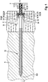
- a hanger bolt 2 according to the invention is shown, which is anchored in an anchoring base 5, here in a wooden beam. To do this, the hanger bolt 2 was screwed directly into the anchoring base 5.
- the hanger bolt 2 according to the invention extends along a longitudinal axis L from a conically tapering screw tip 8, which forms the front end 9 of the hanger bolt 2, to a rear end 6.
- the hanger bolt 2 is designed in several parts and comprises a front part 10 and a rear part 11 as separate individual parts, which are connected to one another axially by means of an adapter sleeve 12 and are also connected to one another in a rotationally fixed manner here by frictional engagement.
- the front part 10 of the hanger bolt 2 is a wood screw, which includes a first threaded section 13 and a screw head 14 .
- the wood screw is made from carbon steel and is electro-galvanized to protect against corrosion.
- the screw head 14 is designed as a countersunk head with a conical front side 15 .
- the screw head 14 has a larger outside diameter than the first threaded section 13 .
- the rear part 11 of the hanger bolt 2 is a cylindrical threaded rod 16 which has a second threaded portion 32 and is made of stainless steel.
- An adapter plate 7 made of an aluminum alloy is screwed onto the threaded rod 16 by means of a threaded sleeve 17 which is fastened to the adapter plate 7 and forms the rear end 6 of the hanger bolt 2 .
- the adapter plate 7 is arranged outside of a thermal insulation 30 applied to the anchoring base 5 .
- the adapter plate 7 could be flush with the thermal insulation 30 .
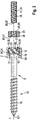
- the adapter sleeve 12 is a cylindrical sleeve with a continuous stepped bore 18 forming a through hole 33, which has at the rear a rear portion 35 with a diameter larger than the diameter of the screw head 14 and in which a first internal metric thread 19 of size M16 is arranged as the first connecting thread 22. Between the section with the larger diameter and a front section 35 with a smaller diameter, the stepped bore 18 has a conical transition section 20 which has a first Stop 21 forms for the front side 15 of the screw head 14 on which the screw head 14 rests flat and is supported.
- the adapter sleeve 12 completely surrounds the screw head 14 in the circumferential direction.
- a reducer 23 of the adapter sleeve 12 is screwed into the first connecting thread 22, which has an external thread 24 of size M16 and an internal thread of size M10 as the second connecting thread 29, into which the threaded rod 16 is screwed.
- the adapter sleeve 12 can have wrench flats on its outside, so that when the reducer 23 is screwed in with a tool, the adapter sleeve 12 can be prevented from turning as well.
- a chemical screw lock can be provided on the reducer 23 and on the threaded rod 16 in order to permanently prevent the parts from becoming detached from the adapter sleeve 12 .
- the front sides of the reducer 23 and the threaded rod 16 each form an abutment element 26 and rest as a second stop 27 on a rear side 28 of the screw head 14 so that the screw head 14 is supported on the second stop 27 .
- the screw head 14 is clamped between the adapter sleeve 12 and the rear part 11 of the hanger bolt 2 in a form-fitting axially fixed manner and frictionally in a rotationally fixed manner, so that forces can be transmitted between the rear part 11 and the front part 10 via the adapter sleeve 12 .
- Both the adapter sleeve 12 and the reducer 23 are made of stainless steel and, like the rear part 11, are more corrosion-resistant than the front part 10 of the hanger bolt 2. If the hanger bolt 2 is used outside of a building, as is shown in figure 1 for an application for fastening a facade cladding (not shown) to the anchoring base 5, with the facade cladding being able to be fastened to the adapter plate 7, the front part 10 of the hanger bolt 2 can be arranged in the area or behind the thermal insulation 30, protected from the effects of the weather, while the rear part 11 is exposed to the elements and is therefore made of stainless steel. In order to avoid contact corrosion, a separating element 31 in the form of a thin plastic sleeve surrounding the screw head 14 is arranged between the front part 10 and the adapter sleeve 12 and the rear part 11 .
- the screw head 14 is designed as a hexagon with an embossed washer, which in this case forms the front side 15 of the screw head 14 .
- the first stop 21 formed by the stepped bore 18 of the through-opening 33 is designed in the shape of a dome here, so that the front side 15 of the screw head 14 rests against the stop 21 only at its edges and thus linearly, whereby an inclined position of the adapter sleeve 21 relative to the longitudinal axis L is possible.
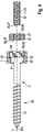
- FIG 5 a fastening system according to the invention is shown, which combines a hanger bolt 2 according to the invention with an expansion anchor 1 .
- the expansion dowel 1 is placed in a drilled hole 4 and is spread open as the front part 10 of the hanger bolt 2 by screwing in a dowel screw.
- a part, namely the rear end, of the anchor sleeve 3 of the expansion anchor 1 is accommodated in the adapter sleeve 12 and arranged as a separating element 31 between the adapter sleeve 12 and the front side 15 of the screw head 14 .
Abstract
Die Erfindung betrifft eine Stockschraube (2), die sich entlang einer Längsachse (L) von einer Schraubenspitze (8) an einem vorderen Ende (9) zu einem hinteren Ende (6) erstreckt. Die Stockschraube (2) weist einen vorderen Teil (10) und einen hinteren Teil (11) als zwei separate Einzelteile auf, die durch eine Adapterhülse (12), die den Schraubenkopf (14) umgreift, verbunden sind.The invention relates to a hanger bolt (2) which extends along a longitudinal axis (L) from a screw tip (8) at a front end (9) to a rear end (6). The hanger bolt (2) has a front part (10) and a rear part (11) as two separate individual parts which are connected by an adapter sleeve (12) which surrounds the screw head (14).
Description
Die Erfindung betrifft eine Stockschraube mit den Merkmalen des Oberbegriffs des Anspruchs 1 sowie ein Befestigungssystem mit dieser Stockschraube gemäß Anspruch 10.The invention relates to a hanger bolt with the features of the preamble of
Stockschrauben sind allgemein als Befestigungsschrauben bekannt, die an einem vorderen Teil einen ersten Gewindeabschnitt zum Einschrauben in einen Verankerungsgrund und an einem hinteren Teil ein insbesondere metrisches Maschinengewinde zum Aufschrauben einer Mutter aufweisen. Die Ausgestaltung des ersten Gewindeabschnitts ist abhängig vom Verankerungsgrund, in den dieser Gewindeabschnitt eingeschraubt werden soll. Ist der Verankerungsgrund aus Holz, so kann der erste Gewindeabschnitt so ausgestaltet sein, wie dies von Holz- oder Spanplattenschrauben bekannt ist. Ist der Verankerungsgrund aus Beton, so kann das Gewinde einer Betonschraube vorgesehen werden, so dass der erste Gewindeabschnitt direkt in ein Bohrloch im Beton eingeschraubt werden kann. Zur Verankerung in Metall kann dagegen der erste Gewindeabschnitt so ausgebildet sein, wie es von selbstbohrenden oder selbstfurchenden Schrauben zur Verankerung in Stahlblechen bekannt ist. Soll dagegen die Verankerung im Bohrloch indirekt mit einem Spreizdübel erfolgen, so kann der erste Gewindeabschnitt ein spezielles Dübelgewinde aufweisen, wie dies beispielsweise von sogenannten Sicherheitsschrauben bekannt ist, die üblicherweise für bauaufsichtlich zugelassene Langschaftdübel verwendet werden.Hanger bolts are generally known as fastening screws, which have a first threaded section on a front part for screwing into an anchoring base and on a rear part, in particular, a metric machine thread for screwing on a nut. The configuration of the first threaded section depends on the anchoring base into which this threaded section is to be screwed. If the anchoring base is made of wood, the first threaded section can be configured in the manner known from wood or chipboard screws. If the anchoring base is made of concrete, the thread of a concrete screw can be provided so that the first threaded section can be screwed directly into a drilled hole in the concrete. For anchoring in metal, on the other hand, the first threaded section can be designed in a manner known from self-drilling or self-tapping screws for anchoring in sheet steel. If, on the other hand, the anchoring in the borehole is to take place indirectly with an expansion anchor, the first threaded section can have a special anchor thread, as is known, for example, from so-called safety screws, which are usually used for long-shaft anchors approved by the building authorities.
Aus der Offenlegungsschrift
Aus der
Nachteilig an den bekannten Stockschrauben ist, dass ein Handwerker Stockschrauben unterschiedlicher Länge mit sich führen muss, um auf der Baustelle auf unterschiedliche Einbausituationen mit variierenden Abständen zwischen Verankerungsgrund und Anbauteil reagieren zu können.A disadvantage of the known hanger bolts is that a craftsman has to carry hanger bolts of different lengths with him in order to be able to react to different installation situations on the construction site with varying distances between the anchoring base and the attachment.
Aufgabe der Erfindung ist es daher, eine Stockschraube vorzuschlagen, die auf einfache Art und Weise auf unterschiedliche Einbausituationen angepasst werden kann.The object of the invention is therefore to propose a hanger bolt that can be easily adapted to different installation situations.
Diese Aufgabe wird erfindungsgemäß durch eine Stockschraube mit den Merkmalen des Anspruchs 1 gelöst. Die erfindungsgemäße Stockschraube erstreckt sich entlang einer Längsachse von einer Schraubenspitze an einem vorderen Ende zu einem hinteren Ende. "Schraubenspitze" meint hier den Teil der Stockschraube, der beim planmäßigen Einbringen der Stockschraube als erstes in den Verankerungsgrund eintritt. Die Schraubenspitze muss dabei nicht zwingend spitz zulaufen, wie dies von Holz- oder Spanplattenschrauben bekannt ist, sondern kann auch abgerundet oder abgeflacht sein, wie dies beispielsweise von Sicherheitsschrauben für Langschaftdübel oder von Betonschrauben bekannt ist. Die Stockschraube umfasst zwei Teile: Einen vorderen Teil mit einem ersten Gewindeabschnitt und einem Schraubenkopf und einen hinteren Teil mit einem zweiten Gewindeabschnitt.According to the invention, this object is achieved by a hanger bolt having the features of
Der erste Gewindeabschnitt ist zum direkten Einschrauben in einen Verankerungsgrund ausgebildet, insbesondere zum Einschrauben in Holz als Holz- beziehungsweise Spanplattengewinde, oder zum Einschrauben in ein Bohrloch in einem mineralischen Verankerungsgrund als Dübel- oder Betonschraubengewinde. Der Schraubenkopf weist einen größeren Durchmesser auf, als ein Kern des ersten Gewindeabschnitts. Insbesondere ist der Durchmesser des Schraubenkopfs größer als ein Außendurchmesser des ersten Gewindeabschnitts. Der Schraubenkopf weist insbesondere ein Angriffsmittel für ein Drehwerkzeug auf, also beispielsweise einen Innenmehrkant oder Kreuzschlitz, oder einen Außenmehrkant, an dem beispielsweise ein entsprechender Bit eines Akkuschraubers oder ein Schraubenschlüssel angesetzt werden kann. Beispielsweise weist der Schraubenkopf einen sich von vorne nach hinten erweiternden kegelstumpfförmigen Abschnitt auf, wie dies von Senkkopfschrauben bekannt ist. Auch andere Formen des Schraubenkopfs sind möglich.The first threaded section is designed for direct screwing into an anchoring base, in particular for screwing into wood as a wood or chipboard thread, or for screwing into a borehole in a mineral anchoring base as a dowel or concrete screw thread. The screw head has a larger diameter than a core of the first threaded section. In particular, the diameter of the screw head is larger than one Outside diameter of the first thread section. The screw head has, in particular, an attachment means for a rotary tool, for example a polygon socket or a Phillips head, or an external polygon on which, for example, a corresponding bit of a cordless screwdriver or a wrench can be attached. For example, the screw head has a frustoconical section that widens from the front to the rear, as is known from countersunk screws. Other shapes of the screw head are also possible.
Mit "Durchmesser" ist hier bei Außendurchmessern stets der Durchmesser eines die Kontur umschreibenden Kreises und bei Innendurchmessern stets der Durchmesser eines eingeschriebenen Kreises gemeint, sofern die jeweiligen Konturen nicht ohnehin kreisrund sind."Diameter" here always means the diameter of a circle circumscribing the contour for outside diameters and always means the diameter of an inscribed circle for inside diameters, provided the respective contours are not circular anyway.
Der zweite Gewindeabschnitt des hinteren Teils der Stockschraube ist als Maschinengewinde, insbesondere als Außengewinde und insbesondere als metrisches Maschinengewinde ausgebildet, sodass eine Mutter, insbesondere eine Mutter nach DIN EN ISO 4032:2013-04 oder ein Bauteil mit entsprechendem Innengewinde aufgeschraubt werden kann.The second threaded section of the rear part of the hanger bolt is designed as a machine thread, in particular as an external thread and in particular as a metric machine thread, so that a nut, in particular a nut according to DIN EN ISO 4032:2013-04, or a component with a corresponding internal thread can be screwed on.
Erfindungsgemäß sind der vordere Teil und der hintere Teil der Stockschraube zwei separate Einzelteile. Die erfindungsgemäße Stockschraube weist eine Adapterhülse auf, die den Schraubenkopf umgreift, diesen also zumindest teilweise umfasst, und die den vorderen Teil der Stockschraube mit dem hinteren Teil der Stockschraube verbindet. Insbesondere greift die Adapterhülse derart am Schraubenkopf an, dass die Verbindung zwischen der Adapterhülse und dem vorderen Teil ausschließlich über den Schraubenkopf erfolgt.According to the invention, the front part and the rear part of the hanger bolt are two separate individual parts. The hanger bolt according to the invention has an adapter sleeve which surrounds the screw head, ie at least partially surrounds it, and which connects the front part of the hanger bolt to the rear part of the hanger bolt. In particular, the adapter sleeve acts on the screw head in such a way that the connection between the adapter sleeve and the front part takes place exclusively via the screw head.
Zum Einbringen des Schraubenkopfs in die Adapterhülse und zum Durchführen der Schraubenspitze durch die Adapterhülse weist die Adapterhülse erfindungsgemäß eine Durchgangsöffnung auf, die einen vorderen und einen hinteren Abschnitt aufweist, die sich in ihren Durchmessern unterscheiden. Der vordere Abschnitt weist einen Durchmesser auf, der kleiner als der Durchmesser des Schraubenkopfs ist, während der hintere Abschnitt einen Durchmesser aufweist, der größer als der Durchmesser des Schraubenkopfs ist. Hierdurch wird in der Durchgangsöffnung ein Anschlag für den Schraubenkopf gebildet, wie er weiter unten beschrieben ist.In order to insert the screw head into the adapter sleeve and to pass the screw tip through the adapter sleeve, the adapter sleeve according to the invention has a through-opening which has a front and a rear section which differ in their diameters. The front section has a diameter that is smaller than the diameter of the screw head, while the rear section has a diameter that is larger than the diameter of the screw head. As a result, a stop for the screw head is formed in the through-opening, as is described further below.
Durch die mehrteilige Ausbildung der Verbindung des hinteren Teils der Stockschraube mit dem vorderen Teil der Stockschraube mittels der Adapterhülse kann der hintere Teil, beispielsweise ein Gewindestift mit metrischem Maschinengewinde, mit praktisch jeder beliebigen handelsüblichen Holz-, Spanplatten-, Beton- oder Dübelschraube oder einer Schraube zum Einschrauben in Stahlblech kombiniert werden. Somit kann mit dem hinteren Teil und der Adapterhülse beispielsweise mit einer Holzbauschraube oder einer Sicherheitsschraube für einen Langschaftdübel eine für die jeweilige Anwendung angepasste Stockschraube hergestellt werden. Das Mitführen von Holz- und Betonschrauben, Langschaftdübeln und zusätzlichen Stockschrauben jeweils unterschiedlicher Länge ist nicht mehr notwendig. Es genügt, wenn der Anwender unterschiedlich lange Schrauben sowie die Adapterhülse und den hinteren Teil, beispielsweise einen Gewindestift oder ein Reduzierstück, mit sich führt. Die Anzahl der Befestigungsmittel, die der Anwender im Lager oder auf der Baustelle vorzuhalten hat, wird durch die Erfindung erheblich reduziert.Due to the multi-part design of the connection of the rear part of the hanger bolt with the front part of the hanger bolt by means of the adapter sleeve, the rear part, for example a threaded pin with a metric machine thread, can be connected with practically any commercially available wood, chipboard, concrete or dowel screw or screw for screwing into sheet steel. Thus, with the rear part and the adapter sleeve, a hanger bolt adapted for the respective application can be produced, for example with a wood construction screw or a safety screw for a long-shaft dowel. It is no longer necessary to carry wood and concrete screws, long-shaft dowels and additional hanger bolts of different lengths. It is sufficient if the user carries screws of different lengths as well as the adapter sleeve and the rear part, for example a threaded pin or a reducer. The number of fasteners that the user has to keep in stock or on site is significantly reduced by the invention.
In einer bevorzugten Ausgestaltungsform weist die erfindungsgemäße Stockschraube einen ersten Anschlag für den Schraubenkopf auf, an dem sich der Schraubenkopf mit einer Vorderseite abstützt. Die Abstützung kann direkt oder indirekt über ein Trennelement, beispielsweise eine Dübelhülse erfolgen. Durch die Anlage des Schraubenkopfs am Anschlag ist gewährleistet, dass Zugkräfte, die auf den hinteren Teil der Stockschraube wirken, über die Adapterhülse auf den vorderen Teil der Stockschraube übertragen werden. Insbesondere weist der erste Anschlag die Form eines umlaufenden, über den gesamten Umfang des Schraubenkopfs anliegenden Ringbunds auf, sodass eine flächige Anlage zwischen Schraubenkopf und Adapterhülse möglich ist. Der Ringbund weist beispielsweise eine ebene Fläche oder eine konische Form auf, die mit einer ebenen beziehungsweise einer kegelstumpfförmigen Vorderseite des Schraubenkopfs korrespondiert, wodurch eine flächige Anlage und somit eine gute Kraftübertragung möglich ist. Alternativ ist auch nur eine punktuelle Auflage möglich.In a preferred embodiment, the hanger bolt according to the invention has a first stop for the screw head, on which the screw head is supported with a front side. The support can be direct or indirect via a separating element, for example a dowel sleeve. The attachment of the screw head to the stop ensures that tensile forces acting on the rear part of the hanger bolt are transferred to the front part of the hanger bolt via the adapter sleeve. In particular, the first stop is in the form of a circumferential annular collar that rests over the entire circumference of the screw head, so that flat contact between the screw head and the adapter sleeve is possible. The annular collar has, for example, a flat surface or a conical shape that corresponds to a flat or frustoconical front side of the screw head, as a result of which flat contact and thus good power transmission is possible. Alternatively, only a selective support is possible.
Vorzugsweise ist der Anschlag kalottenförmig ausgebildet, derart, dass die Adapterhülse gegenüber dem vorderen Teil bezogen auf die Längsachse, die in diesem Fall durch den vorderen Teil definiert wird, in einfacher Weise um einen Winkel geneigt beziehungsweise geschwenkt werden kann.The stop is preferably designed in the shape of a spherical cap, such that the adapter sleeve can easily be tilted or pivoted at an angle relative to the front part in relation to the longitudinal axis, which in this case is defined by the front part.
Weiterhin ist bevorzugt, dass die Adapterhülse ein erstes Verbindungsgewinde zur Verbindung mit dem hinteren Teil aufweist. Der hintere Teil kann insbesondere ein Gewindestift oder eine Gewindestange mit gleichbleibendem Außendurchmesser oder ein Reduzierstück sein, also ein Bauteil mit zwei Gewinden, die unterschiedliche Durchmesser aufweisen. Das Reduzierstück kann beispielsweise zwei Außengewinde, zwei Innengewinde oder aber ein Außen- und ein Innengewinde mit unterschiedlichen Durchmessern aufweisen. Alternativ kann statt Gewinden ein Art Bajonettverschluss, eine Rastverbindung oder eine sonstige formschlüssige Verbindung vorgesehen werden.Furthermore, it is preferred that the adapter sleeve has a first connection thread for connection to the rear part. The rear part can be a particular A threaded pin or a threaded rod with a constant outer diameter or a reducer, i.e. a component with two threads that have different diameters. The reducer can have, for example, two external threads, two internal threads or one external and one internal thread with different diameters. Alternatively, instead of threads, a type of bayonet catch, a latching connection or some other form-fitting connection can be provided.
Weiterhin ist bevorzugt, dass der hintere Teil und/oder die Adapterhülse ein Widerlagerelement aufweisen, das einen zweiten Anschlag bildet, an dem sich der Schraubenkopf mit einer Rückseite abstützt. Insbesondere liegt das Widerlagerelement am Schraubenkopf an. Es ist ein direkter Kontakt zwischen den Anschlägen und dem Schraubenkopf oder ein indirekter Kontakt über ein dazwischenliegendes Zwischenelement möglich. Das Widerlagerelement kann insbesondere durch eine Vorderseite des hinteren Teils und/oder der Adapterhülse gebildet werden. Durch die Abstützung des zweiten Anschlags am Schraubenkopf können Druckkräfte vom hinteren Teil auf den vorderen Teil übertragen werden.Furthermore, it is preferred that the rear part and/or the adapter sleeve have an abutment element which forms a second stop on which the screw head is supported with a rear side. In particular, the abutment element rests against the screw head. Direct contact between the stops and the screw head or indirect contact via an intermediate element in between is possible. The abutment element can be formed in particular by a front side of the rear part and/or the adapter sleeve. By supporting the second stop on the screw head, compressive forces can be transferred from the rear part to the front part.
Ein direkter oder indirekter Kontakt des ersten Anschlags und des zweiten Anschlags mit dem Schraubenkopf verhindert, dass der hintere Teil zum vorderen Teil axial beweglich ist. Zudem kann durch ein Verspannen der beiden Anschläge mit dem Schraubenkopf eine reibschlüssige Verbindung hergestellt werden, sodass der hintere Teil nicht relativ zum vorderen Teil um die Längsachse gedreht werden kann. Ist der hintere Teil beispielsweise ein Gewindestift, so kann dieser in die Adapterhülse eingeschraubt und gegen die Rückseite des Schraubenkopfs verspannt werden, sodass die Adapterhülse an der Vorderseite und das Widerlagerelement an der Rückseite des Schraubenkopfs anliegt und somit die Adapterhülse spielfrei und durch Reibschluss verdrehsicher mit dem Schraubenkopf verbunden ist.Direct or indirect contact of the first stop and the second stop with the screw head prevents the rear part from being axially movable towards the front part. In addition, by bracing the two stops with the screw head, a frictional connection can be established, so that the rear part cannot be rotated about the longitudinal axis relative to the front part. If the rear part is a threaded pin, for example, it can be screwed into the adapter sleeve and clamped against the back of the screw head, so that the adapter sleeve rests on the front and the counter bearing element on the back of the screw head, and the adapter sleeve is thus free of play and secured against rotation with the screw head is connected.
Weiterhin ist bevorzugt, dass der hintere Teil und/oder die Adapterhülse zwei Gewinde mit unterschiedlichen Durchmessern umfasst. Der hintere Teil kann beispielsweise einstückig oder mehrteilig ausgebildet sein. Die Verwendung eines hinteren Teils mit zwei Gewinden hat den Vorteil, dass der zweite Gewindeabschnitt des hinteren Teils an das zu befestigende Anbauteil angepasst werden kann, ohne dass die Adapterhülse geändert werden muss. Weist die Adapterhülse beispielsweise ein Innengewinde zur Aufnahme des hinteren Teils auf, so kann durch die Verwendung unterschiedlicher hinterer Teile die Stockschraube an verschiedene Anbauteile angepasst werden. Weist die Adapterhülse beispielsweise ein Innengewinde der Größe M16 zur Aufnahme des hinteren Teils auf, so kann das hintere Teil ein einteiliges Gewindestück mit einem in die Adapterhülse einzudrehenden Außengewinde der Größe M16 und einem den zweiten Gewindeabschnitt der Stockschraube bildenden Außengewinde beispielsweise der Größe M8 sein, an dem das Anbauteil mit einer Mutter befestigt werden kann.Furthermore, it is preferred that the rear part and/or the adapter sleeve comprises two threads with different diameters. The rear part can, for example, be designed in one piece or in several parts. The use of a rear part with two threads has the advantage that the second threaded section of the rear part can be adapted to the attachment to be attached without having to change the adapter sleeve. If the adapter sleeve has, for example, an internal thread for accommodating the rear part, the hanger bolt can be adapted to different add-on parts by using different rear parts. points For example, if the adapter sleeve has an internal thread of size M16 for receiving the rear part, the rear part can be a one-piece threaded piece with an external thread of size M16 to be screwed into the adapter sleeve and an external thread of size M8, for example, forming the second threaded section of the hanger bolt, on which the attachment can be fastened with a nut.
Bei einer bevorzugten Ausgestaltungsform der erfindungsgemäßen Stockschraube ist der hintere Teil korrosionsbeständiger ausgebildet als der vordere Teil. "Korrosionsbeständiger" meint hier, dass der Widerstand gegen Korrosion bei einer feuchten Atmosphäre größer ist. Beispielsweise ist einem Fachmann als "rostfreier Stahl" bekannter Stahl für diesen Anwendungsfall korrosionsbeständiger als feuerverzinkter Normalstahl, der wiederum bei identischen Umgebungsbedingungen korrosionsbeständiger als galvanisch verzinkter Normalstahl ist. Insbesondere besteht der vordere Teil aus einem galvanisch verzinkten Normalstoffstahl, wie dies bei Holzbauschrauben für den Innenbereich üblich ist, während der hintere Teil aus einem Edelstahl hergestellt ist. Somit lässt sich die erfindungsgemäße Stockschraube auf einfache Weise an die jeweilige Einbausituation beziehungsweise die Umgebungsbedingungen anpassen. Kann beispielsweise bei einer Fassadenanwendung, also dann, wenn die Stockschraube im Außenbereich an Gebäuden eingesetzt wird, gewährleistet werden, dass der vordere Teil nicht, sondern nur der hintere Teil in einer feuchten Umgebung angeordnet wird, kann für den vorderen Teil eine gewöhnliche galvanisch verzinkte Schraube verwendet werden, während der hintere Teil aus korrosionsbeständigem Stahl besteht. Abhängig von dem Umgebungsbedingungen kann die Adapterhülse aus korrosionsbeständigem Stahl oder galvanisch verzinktem Stahl hergestellt werden.In a preferred embodiment of the hanger bolt according to the invention, the rear part is designed to be more corrosion-resistant than the front part. "More corrosion resistant" here means that the resistance to corrosion is greater in a humid atmosphere. For example, steel known to a person skilled in the art as "stainless steel" is more corrosion-resistant for this application than hot-dip galvanized normal steel, which in turn is more corrosion-resistant than galvanized normal steel under identical environmental conditions. In particular, the front part consists of an electrogalvanized standard steel, as is usual with wood construction screws for indoor use, while the rear part is made of stainless steel. The hanger bolt according to the invention can thus be easily adapted to the respective installation situation or the environmental conditions. If, for example, in a facade application, i.e. when the hanger bolt is used outdoors on buildings, it can be ensured that the front part is not but only the rear part in a damp environment, a normal galvanized screw can be used for the front part be used, while the rear part is made of corrosion-resistant steel. Depending on the environmental conditions, the adapter sleeve can be made of corrosion-resistant steel or electro-galvanized steel.
Zur Vermeidung von Kontaktkorrosion ist vorzugsweise zwischen dem vorderen Teil und der Adapterhülse und/oder dem hinteren Teil ein Trennelement angeordnet. Das Trennelement kann insbesondere aus Kunststoff bestehen. Vorzugsweise ist zwischen der Adapterhülse und dem Schraubenkopf ein Teil einer Dübelhülse eines Spreizdübels angeordnet. Zudem oder alternativ kann zwischen dem Schraubenkopf und dem hinteren Teil ein weiteres Trennelement angeordnet werden, beispielsweise in Form einer Kunststoffscheibe, die zudem die Funktion erfüllen kann, den Schraubenkopf in der Adapterhülse gegen ein Herausbewegen zu sichern.To avoid contact corrosion, a separating element is preferably arranged between the front part and the adapter sleeve and/or the rear part. The separating element can consist in particular of plastic. A part of an anchor sleeve of an expansion anchor is preferably arranged between the adapter sleeve and the screw head. In addition or as an alternative, a further separating element can be arranged between the screw head and the rear part, for example in the form of a plastic disc, which can also fulfill the function of securing the screw head in the adapter sleeve against moving out.
Zur Befestigung eines Anbauteils an dem zweiten Gewindeabschnitt kann die erfindungsgemäße Stockschraube am zweiten Gewindeabschnitt eine Adapterplatte aufweisen, die eine flächige Anlage des Anbauteils an der Stockschraube gewährleistet.In order to fasten an attachment to the second threaded section, the hanger bolt according to the invention can have an adapter plate on the second threaded section, which ensures that the attachment is in planar contact with the hanger bolt.
Vorzugsweise bildet die erfindungsgemäße Stockschraube mit einem zugeordneten Spreizdübel aus Kunststoff ein Befestigungssystem. Der Spreizdübel ist insbesondere ein Langschaftdübel zur Verwendung im Außenbereich an Fassaden. Der Spreizdübel ist durch Einschrauben des ersten Gewindeabschnitts, der insbesondere ein Dübelgewinde aufweist, aufspreizbar.The hanger bolt according to the invention preferably forms a fastening system with an associated expansion dowel made of plastic. The expansion anchor is in particular a long-shaft anchor for use outdoors on facades. The expansion dowel can be spread open by screwing in the first threaded section, which in particular has a dowel thread.
Die vorstehend in der Beschreibung genannten Merkmale und Merkmalskombinationen, Ausführungen und Ausgestaltungen der Erfindung, sowie die nachfolgend in der Figurenbeschreibung genannten und/oder in einer Figur gezeichneten Merkmale und Merkmalskombinationen sind nicht nur in der jeweils angegebenen oder gezeichneten Kombination, sondern auch in grundsätzlich beliebigen anderen Kombinationen oder aber einzeln verwendbar. Es sind Ausführungen der Erfindung möglich, die nicht alle Merkmale eines abhängigen Anspruchs aufweisen. Auch können einzelne Merkmale eines Anspruchs durch andere offenbarte Merkmale oder Merkmalskombinationen ersetzt werden. Ausführungen der Erfindung, die nicht alle Merkmale des Ausführungsbeispiels, sondern einen grundsätzlich beliebigen Teil der gekennzeichneten Merkmale des Ausführungsbeispiels aufweisen, sind möglich.The features and combinations of features, versions and configurations of the invention mentioned above in the description, as well as the features and combinations of features mentioned below in the description of the figures and/or drawn in a figure, are not only in the combination specified or drawn, but also in any other combination Can be used in combination or individually. Embodiments of the invention are possible which do not have all the features of a dependent claim. Individual features of a claim can also be replaced by other disclosed features or combinations of features. Embodiments of the invention that do not have all the features of the exemplary embodiment, but basically any part of the characterized features of the exemplary embodiment, are possible.
Die Erfindung wird nachfolgend anhand mehrerer in der Zeichnung dargestellten Ausführungsbeispiele näher erläutert.The invention is explained in more detail below with reference to several exemplary embodiments illustrated in the drawing.
Es zeigen:
Figur 1- eine erfindungsgemäße Stockschraube in einem Verankerungsgrund in einer teilweise geschnittenen Seitenansicht;
Figur 2- die erfindungsgemäße Stockschraube in einem teilweise zusammengebauten Zustand in einem Schnitt;
- Figur 3
- eine perspektivische Darstellung der Adapterhülse und des hinteren Teils;
- Figur 4
- eine alternative Adapterhülse mit einem eingeführten Schraubenkopf; und
Figur 5- ein erfindungsgemäßes Befestigungssystem in einer teilweise geschnittenen Seitenansicht.
- figure 1
- a hanger bolt according to the invention in an anchor base in a partially sectioned side view;
- figure 2
- the hanger bolt according to the invention in a partially assembled state in a section;
- figure 3
- a perspective view of the adapter sleeve and the rear part;
- figure 4
- an alternative adapter sleeve with an inserted screw head; and
- figure 5
- a fastening system according to the invention in a partially sectioned side view.
In
Der vordere Teil 10 der Stockschraube 2 ist eine Holzschraube, die einen ersten Gewindeabschnitt 13 und einen Schraubenkopf 14 umfasst. Die Holzschraube ist aus einem Kohlenstoffstahl hergestellt und zum Schutz vor Korrosion galvanisch verzinkt. Der Schraubenkopf 14 ist als Senkkopf mit einer konischen Vorderseite 15 ausgestaltet. Der Schraubenkopf 14 weist einen größeren Außendurchmesser als der erste Gewindeabschnitt 13 auf.The
Der hintere Teil 11 der Stockschraube 2 ist eine zylindrische Gewindestange 16, die einen zweiten Gewindeabschnitt 32 aufweist und aus Edelstahl hergestellt ist. Auf die Gewindestange 16 ist eine Adapterplatte 7 aus einer Aluminiumlegierung mittels einer an der Adapterplatte 7 befestigten Gewindehülse 17 aufgeschraubt, die das hintere Ende 6 der Stockschraube 2 bildet. In
Die Adapterhülse 12 ist eine zylindrische Hülse mit einer durchgehenden Stufenbohrung 18, die eine Durchgangsöffnung 33 bildet, die hinten einen hinteren Abschnitt 35 mit einem Durchmesser aufweist, der größer als der Durchmesser des Schraubenkopfs 14 ist und in dem ein erstes metrisches Innengewinde 19 der Größe M16 als erstes Verbindungsgewinde 22 angeordnet ist. Zwischen dem Abschnitt mit dem größeren Durchmesser und einem vorderen Abschnitt 35 mit kleinerem Durchmesser weist die Stufenbohrung 18 einen konischen Übergangsabschnitt 20 auf, der einen ersten Anschlag 21 für die Vorderseite 15 des Schraubenkopfs 14 bildet, an dem der Schraubenkopf 14 flächig anliegt und sich abstützt. Die Adapterhülse 12 umgreift den Schraubenkopf 14 in Umfangsrichtung vollständig.The
Im zusammengebauten Zustand der
Die Vorderseiten des Reduzierstücks 23 und der Gewindestange 16 bilden jeweils ein Widerlagerelement 26 und liegen als zweiter Anschlag 27 an einer Rückseite 28 des Schraubenkopfs 14 an, so dass sich der Schraubenkopf 14 am zweiten Anschlag 27 abstützt. Der Schraubenkopf 14 ist zwischen der Adapterhülse 12 und dem hinteren Teil 11 der Stockschraube 2 formschlüssig axialfest und reibschlüssig drehfest eingespannt, so dass Kräfte zwischen dem hinteren Teil 11 und dem vorderen Teil 10 über die Adapterhülse 12 übertragen werden können.The front sides of the
Sowohl die Adapterhülse 12 als auch das Reduzierstück 23 sind aus Edelstahl hergestellt und somit wie der hintere Teil 11 korrosionsbeständiger ausgebildet als der vordere Teil 10 der Stockschraube 2. Wird die Stockschraube 2 im Außenbereich eines Gebäudes verwendet, wie dies in
Abweichend von der in den
In
- 11
- Spreizdübelexpansion anchor
- 22
- Stockschraubehanger bolt
- 33
- Dübelhülsedowel sleeve
- 44
- Bohrlochborehole
- 55
- Verankerungsgrundanchoring ground
- 66
-
hinteres Ende der Stockschraube 2rear end of
hanger bolt 2 - 77
- Adapterplatteadapter plate
- 88th
- Schraubenspitzescrew tip
- 99
-
vorderes Ende der Stockschraube 2front end of
hanger bolt 2 - 1010
-
vorderer Teil der Stockschraube 2front part of
hanger bolt 2 - 1111
-
hinterer Teil der Stockschraube 2rear part of
hanger bolt 2 - 1212
- Adapterhülseadapter sleeve
- 1313
- erster Gewindeabschnittfirst thread section
- 1414
- Schraubenkopfscrew head
- 1515
-
Vorderseite des Schraubenkopfs 14Front of
screw head 14 - 1616
- Gewindestangethreaded rod
- 1717
-
Gewindehülse der Adapterplatte 7Threaded sleeve of the
adapter plate 7 - 1818
- Stufenbohrungstepped bore
- 1919
- erstes Innengewindefirst internal thread
- 2020
- Übergangsabschnitt der Stufenbohrung 18Transition section of the stepped bore 18
- 2121
- erster Anschlagfirst stop
- 2222
- erstes Verbindungsgewindefirst connecting thread
- 2323
- Reduzierstückreducer
- 2424
-
Außengewinde des Reduzierstücks 23External thread of
reducer 23 - 2525
-
Innengewinde des Reduzierstücks 23Internal thread of
reducer 23 - 2626
- Widerlagerelementabutment element
- 2727
- zweiter Anschlagsecond stop
- 2828
-
Rückseite des Schraubenkopfs 14Back of
screw head 14 - 2929
- zweites Verbindungsgewindesecond connection thread
- 3030
- Wärmedämmungthermal insulation
- 3131
- Trennelementseparator
- 3232
- zweiter Gewindeabschnittsecond thread section
- 3333
- Durchgangsöffnungpassage opening
- 3434
-
vorderer Abschnitt der Durchgangsöffnung 33front section of the through
opening 33 - 3535
-
hinterer Abschnitt der Durchgangsöffnung 33rear section of the through
hole 33 - LL
- Längsachselongitudinal axis
Claims (11)
dadurch gekennzeichnet,
dass die Adapterhülse (12) einen ersten Anschlag (21) für den Schraubenkopf (14) aufweist, an dem sich der Schraubenkopf (14) mit einer Vorderseite (15) abstützt.hanger bolt according to claim 1,
characterized,
that the adapter sleeve (12) has a first stop (21) for the screw head (14), on which the screw head (14) is supported with a front side (15).
dadurch gekennzeichnet,
dass der Anschlag (21) kalottenförmig ausgebildet ist.hanger bolt according to claim 2,
characterized,
that the stop (21) is designed in the shape of a dome.
dadurch gekennzeichnet,
dass die Adapterhülse (12) ein erstes Verbindungsgewinde (22) zur Verbindung mit dem hinteren Teil (11) aufweist.Hanger bolt according to one of the preceding claims,
characterized,
that the adapter sleeve (12) has a first connection thread (22) for connection to the rear part (11).
dadurch gekennzeichnet,
dass der hintere Teil (11) und/oder die Adapterhülse (12) ein Widerlagerelement (26) aufweisen, das einen zweiten Anschlag (27) bildet, an dem sich der Schraubenkopf (14) mit einer Rückseite (28) abstützt.Hanger bolt according to one of the preceding claims,
characterized,
that the rear part (11) and/or the adapter sleeve (12) have an abutment element (26) which forms a second stop (27) on which the screw head (14) is supported with a rear side (28).
dadurch gekennzeichnet,
dass der hintere Teil (11) und/oder die Adapterhülse (14) zwei Gewinde (22, 29, 32) mit unterschiedlichen Durchmessern umfasst.Hanger bolt according to one of the preceding claims,
characterized,
that the rear part (11) and/or the adapter sleeve (14) comprises two threads (22, 29, 32) with different diameters.
dadurch gekennzeichnet,
dass der hintere Teil (11) korrosionsbeständiger ausgebildet ist als der vordere Teil (10).Hanger bolt according to one of the preceding claims,
characterized,
that the rear part (11) is designed to be more corrosion-resistant than the front part (10).
dadurch gekennzeichnet,
dass zwischen dem vorderen Teil (10) und der Adapterhülse (12) und/oder dem hinteren Teil (11) ein Trennelement (31) zum Schutz vor Kontaktkorrosion angeordnet ist.Hanger bolt according to one of the preceding claims,
characterized,
that between the front part (10) and the adapter sleeve (12) and/or the rear part (11) a separating element (31) is arranged to protect against contact corrosion.
dadurch gekennzeichnet,
dass zwischen der Adapterhülse (12) und dem Schraubenkopf (14) ein Teil einer Dübelhülse (3) eines Spreizdübels (1) angeordnet ist.Hanger bolt according to one of the preceding claims,
characterized,
that part of an anchor sleeve (3) of an expansion anchor (1) is arranged between the adapter sleeve (12) and the screw head (14).
Applications Claiming Priority (2)
| Application Number | Priority Date | Filing Date | Title |
|---|---|---|---|
| DE102020124787 | 2020-09-23 | ||
| DE102021118936.5A DE102021118936A1 (en) | 2020-09-23 | 2021-07-22 | Hanger bolt and fastening system with this hanger bolt |
Publications (1)
| Publication Number | Publication Date |
|---|---|
| EP3974667A1 true EP3974667A1 (en) | 2022-03-30 |
Family
ID=77367278
Family Applications (1)
| Application Number | Title | Priority Date | Filing Date |
|---|---|---|---|
| EP21191580.6A Pending EP3974667A1 (en) | 2020-09-23 | 2021-08-17 | Hanger bolt and fastening system using the same |
Country Status (1)
| Country | Link |
|---|---|
| EP (1) | EP3974667A1 (en) |
Cited By (1)
| Publication number | Priority date | Publication date | Assignee | Title |
|---|---|---|---|---|
| DE102022125079A1 (en) | 2022-09-29 | 2024-04-04 | GIP GmbH | System for fixing weatherproof planking in metal or wooden frameworks, their use and installation method |
Citations (4)
| Publication number | Priority date | Publication date | Assignee | Title |
|---|---|---|---|---|
| DE3441561A1 (en) | 1984-11-14 | 1986-05-22 | Franz 6200 Wiesbaden Müller | Shoulder screw or vice screw |
| WO1996022442A1 (en) * | 1995-01-20 | 1996-07-25 | Soederstroem Kurt | An adjustable frame fitting device |
| EP2306032B1 (en) | 2009-10-02 | 2014-04-09 | Adolf Würth GmbH & Co. KG | Fastening element |
| DE102017009887A1 (en) * | 2017-10-23 | 2019-04-25 | René Bangratz | Connecting element with locking element and method for fixing the connecting element |
-
2021
- 2021-08-17 EP EP21191580.6A patent/EP3974667A1/en active Pending
Patent Citations (4)
| Publication number | Priority date | Publication date | Assignee | Title |
|---|---|---|---|---|
| DE3441561A1 (en) | 1984-11-14 | 1986-05-22 | Franz 6200 Wiesbaden Müller | Shoulder screw or vice screw |
| WO1996022442A1 (en) * | 1995-01-20 | 1996-07-25 | Soederstroem Kurt | An adjustable frame fitting device |
| EP2306032B1 (en) | 2009-10-02 | 2014-04-09 | Adolf Würth GmbH & Co. KG | Fastening element |
| DE102017009887A1 (en) * | 2017-10-23 | 2019-04-25 | René Bangratz | Connecting element with locking element and method for fixing the connecting element |
Cited By (1)
| Publication number | Priority date | Publication date | Assignee | Title |
|---|---|---|---|---|
| DE102022125079A1 (en) | 2022-09-29 | 2024-04-04 | GIP GmbH | System for fixing weatherproof planking in metal or wooden frameworks, their use and installation method |
Similar Documents
| Publication | Publication Date | Title |
|---|---|---|
| EP1724412B1 (en) | Spacer and method for fixing an article to a support with an exterior insulating layer | |
| DE19947913C2 (en) | Fastening element for attaching loads to a building wall with thermal insulation | |
| EP2666919B1 (en) | Method and mounting system for attaching insulation panels to a support surface | |
| DE10145122A1 (en) | Spacer for the attachment of an object to a wall having an insulating layer | |
| DE102004064114B4 (en) | Fastening element for insulation boards | |
| EP2245317A1 (en) | Fastening element for wood-fibre insulating boards | |
| EP2206931B1 (en) | Screw and its utilisation | |
| EP3974667A1 (en) | Hanger bolt and fastening system using the same | |
| EP2347073B1 (en) | Hinge for doors, windows and similar | |
| DE102015013598B4 (en) | Tolerance compensation element and associated motor vehicle body | |
| EP1046764A1 (en) | Device for distance fixing of isolation panels to walls or ceilings | |
| DE102009019111B4 (en) | dowel | |
| DE102021118936A1 (en) | Hanger bolt and fastening system with this hanger bolt | |
| DE19831269C2 (en) | Window screw | |
| DE3611873A1 (en) | Fastening element for the adjustable fastening of structural elements on structures | |
| EP3567264B1 (en) | Fastening system | |
| DE3333055A1 (en) | Device for fastening laths | |
| DE2701510A1 (en) | Dowel with tapered plug for fixing objects to walls - is expanded radially by shank of bolt engaging internal ridge | |
| EP1680606B1 (en) | Fixing element | |
| EP3336271B1 (en) | Fixing device for fixing a construction element to a component with an insulating layer | |
| EP2182125A2 (en) | Method for securing construction element at a distance from a component | |
| DE102016107377A1 (en) | Plate assembly with a fastening device and a method for forming a plate assembly and fastening device for the plate assembly | |
| EP3421821B1 (en) | Dowel, arrangement with a dowel and use of a dowel | |
| EP3093508B1 (en) | Toggle fastener and method for fixing with a toggle fastener | |
| DE202004015457U1 (en) | Screw fastening element made from carbon steel for support structures comprises a head part with a first shaft section and a second shaft section |
Legal Events
| Date | Code | Title | Description |
|---|---|---|---|
| PUAI | Public reference made under article 153(3) epc to a published international application that has entered the european phase |
Free format text: ORIGINAL CODE: 0009012 |
|
| STAA | Information on the status of an ep patent application or granted ep patent |
Free format text: STATUS: THE APPLICATION HAS BEEN PUBLISHED |
|
| AK | Designated contracting states |
Kind code of ref document: A1 Designated state(s): AL AT BE BG CH CY CZ DE DK EE ES FI FR GB GR HR HU IE IS IT LI LT LU LV MC MK MT NL NO PL PT RO RS SE SI SK SM TR |
|
| STAA | Information on the status of an ep patent application or granted ep patent |
Free format text: STATUS: REQUEST FOR EXAMINATION WAS MADE |
|
| 17P | Request for examination filed |
Effective date: 20220923 |
|
| RBV | Designated contracting states (corrected) |
Designated state(s): AL AT BE BG CH CY CZ DE DK EE ES FI FR GB GR HR HU IE IS IT LI LT LU LV MC MK MT NL NO PL PT RO RS SE SI SK SM TR |
|
| RIC1 | Information provided on ipc code assigned before grant |
Ipc: F16B 5/02 20060101ALN20230721BHEP Ipc: F16B 13/02 20060101ALN20230721BHEP Ipc: F16B 37/12 20060101ALI20230721BHEP Ipc: F16B 35/00 20060101AFI20230721BHEP |
|
| RIC1 | Information provided on ipc code assigned before grant |
Ipc: F16B 5/02 20060101ALN20230901BHEP Ipc: F16B 13/02 20060101ALN20230901BHEP Ipc: F16B 37/12 20060101ALI20230901BHEP Ipc: F16B 35/00 20060101AFI20230901BHEP |
|
| GRAP | Despatch of communication of intention to grant a patent |
Free format text: ORIGINAL CODE: EPIDOSNIGR1 |
|
| STAA | Information on the status of an ep patent application or granted ep patent |
Free format text: STATUS: GRANT OF PATENT IS INTENDED |
|
| INTG | Intention to grant announced |
Effective date: 20231016 |