EP3974594B1 - Wall - Google Patents
Wall Download PDFInfo
- Publication number
- EP3974594B1 EP3974594B1 EP21199071.8A EP21199071A EP3974594B1 EP 3974594 B1 EP3974594 B1 EP 3974594B1 EP 21199071 A EP21199071 A EP 21199071A EP 3974594 B1 EP3974594 B1 EP 3974594B1
- Authority
- EP
- European Patent Office
- Prior art keywords
- brick
- groove
- cross
- bricks
- longitudinal
- Prior art date
- Legal status (The legal status is an assumption and is not a legal conclusion. Google has not performed a legal analysis and makes no representation as to the accuracy of the status listed.)
- Active
Links
- 239000011449 brick Substances 0.000 claims description 131
- 239000002023 wood Substances 0.000 claims description 12
- 239000007787 solid Substances 0.000 claims description 5
- 239000004575 stone Substances 0.000 description 8
- 239000003292 glue Substances 0.000 description 4
- 241000218657 Picea Species 0.000 description 2
- 239000002131 composite material Substances 0.000 description 2
- 230000000694 effects Effects 0.000 description 2
- 238000003780 insertion Methods 0.000 description 2
- 230000037431 insertion Effects 0.000 description 2
- 238000009413 insulation Methods 0.000 description 2
- 240000000731 Fagus sylvatica Species 0.000 description 1
- 235000010099 Fagus sylvatica Nutrition 0.000 description 1
- 239000000853 adhesive Substances 0.000 description 1
- 230000001070 adhesive effect Effects 0.000 description 1
- 230000004888 barrier function Effects 0.000 description 1
- 239000004832 casein glue Substances 0.000 description 1
- 239000004927 clay Substances 0.000 description 1
- 238000009792 diffusion process Methods 0.000 description 1
- 230000007613 environmental effect Effects 0.000 description 1
- 239000012774 insulation material Substances 0.000 description 1
- 238000003801 milling Methods 0.000 description 1
- 239000002994 raw material Substances 0.000 description 1
- 239000010876 untreated wood Substances 0.000 description 1
- XLYOFNOQVPJJNP-UHFFFAOYSA-N water Substances O XLYOFNOQVPJJNP-UHFFFAOYSA-N 0.000 description 1
Images


Classifications
-
- E—FIXED CONSTRUCTIONS
- E04—BUILDING
- E04C—STRUCTURAL ELEMENTS; BUILDING MATERIALS
- E04C1/00—Building elements of block or other shape for the construction of parts of buildings
-
- E—FIXED CONSTRUCTIONS
- E04—BUILDING
- E04C—STRUCTURAL ELEMENTS; BUILDING MATERIALS
- E04C2/00—Building elements of relatively thin form for the construction of parts of buildings, e.g. sheet materials, slabs, or panels
- E04C2/02—Building elements of relatively thin form for the construction of parts of buildings, e.g. sheet materials, slabs, or panels characterised by specified materials
- E04C2/10—Building elements of relatively thin form for the construction of parts of buildings, e.g. sheet materials, slabs, or panels characterised by specified materials of wood, fibres, chips, vegetable stems, or the like; of plastics; of foamed products
-
- E—FIXED CONSTRUCTIONS
- E04—BUILDING
- E04B—GENERAL BUILDING CONSTRUCTIONS; WALLS, e.g. PARTITIONS; ROOFS; FLOORS; CEILINGS; INSULATION OR OTHER PROTECTION OF BUILDINGS
- E04B1/00—Constructions in general; Structures which are not restricted either to walls, e.g. partitions, or floors or ceilings or roofs
- E04B1/38—Connections for building structures in general
- E04B1/58—Connections for building structures in general of bar-shaped building elements
- E04B1/5825—Connections for building structures in general of bar-shaped building elements with a closed cross-section
- E04B1/5831—Connections for building structures in general of bar-shaped building elements with a closed cross-section of substantially rectangular form
-
- E—FIXED CONSTRUCTIONS
- E04—BUILDING
- E04B—GENERAL BUILDING CONSTRUCTIONS; WALLS, e.g. PARTITIONS; ROOFS; FLOORS; CEILINGS; INSULATION OR OTHER PROTECTION OF BUILDINGS
- E04B2/00—Walls, e.g. partitions, for buildings; Wall construction with regard to insulation; Connections specially adapted to walls
- E04B2/02—Walls, e.g. partitions, for buildings; Wall construction with regard to insulation; Connections specially adapted to walls built-up from layers of building elements
- E04B2/04—Walls having neither cavities between, nor in, the solid elements
- E04B2/06—Walls having neither cavities between, nor in, the solid elements using elements having specially-designed means for stabilising the position
- E04B2/08—Walls having neither cavities between, nor in, the solid elements using elements having specially-designed means for stabilising the position by interlocking of projections or inserts with indentations, e.g. of tongues, grooves, dovetails
-
- E—FIXED CONSTRUCTIONS
- E04—BUILDING
- E04C—STRUCTURAL ELEMENTS; BUILDING MATERIALS
- E04C2/00—Building elements of relatively thin form for the construction of parts of buildings, e.g. sheet materials, slabs, or panels
- E04C2/02—Building elements of relatively thin form for the construction of parts of buildings, e.g. sheet materials, slabs, or panels characterised by specified materials
- E04C2/10—Building elements of relatively thin form for the construction of parts of buildings, e.g. sheet materials, slabs, or panels characterised by specified materials of wood, fibres, chips, vegetable stems, or the like; of plastics; of foamed products
- E04C2/12—Building elements of relatively thin form for the construction of parts of buildings, e.g. sheet materials, slabs, or panels characterised by specified materials of wood, fibres, chips, vegetable stems, or the like; of plastics; of foamed products of solid wood
-
- E—FIXED CONSTRUCTIONS
- E04—BUILDING
- E04C—STRUCTURAL ELEMENTS; BUILDING MATERIALS
- E04C2/00—Building elements of relatively thin form for the construction of parts of buildings, e.g. sheet materials, slabs, or panels
- E04C2/30—Building elements of relatively thin form for the construction of parts of buildings, e.g. sheet materials, slabs, or panels characterised by the shape or structure
- E04C2/32—Building elements of relatively thin form for the construction of parts of buildings, e.g. sheet materials, slabs, or panels characterised by the shape or structure formed of corrugated or otherwise indented sheet-like material; composed of such layers with or without layers of flat sheet-like material
-
- E—FIXED CONSTRUCTIONS
- E04—BUILDING
- E04C—STRUCTURAL ELEMENTS; BUILDING MATERIALS
- E04C2/00—Building elements of relatively thin form for the construction of parts of buildings, e.g. sheet materials, slabs, or panels
- E04C2/30—Building elements of relatively thin form for the construction of parts of buildings, e.g. sheet materials, slabs, or panels characterised by the shape or structure
- E04C2/38—Building elements of relatively thin form for the construction of parts of buildings, e.g. sheet materials, slabs, or panels characterised by the shape or structure with attached ribs, flanges, or the like, e.g. framed panels
- E04C2/386—Building elements of relatively thin form for the construction of parts of buildings, e.g. sheet materials, slabs, or panels characterised by the shape or structure with attached ribs, flanges, or the like, e.g. framed panels with a frame of unreconstituted or laminated wood
-
- E—FIXED CONSTRUCTIONS
- E04—BUILDING
- E04B—GENERAL BUILDING CONSTRUCTIONS; WALLS, e.g. PARTITIONS; ROOFS; FLOORS; CEILINGS; INSULATION OR OTHER PROTECTION OF BUILDINGS
- E04B2/00—Walls, e.g. partitions, for buildings; Wall construction with regard to insulation; Connections specially adapted to walls
- E04B2/02—Walls, e.g. partitions, for buildings; Wall construction with regard to insulation; Connections specially adapted to walls built-up from layers of building elements
- E04B2002/0202—Details of connections
- E04B2002/0232—Undercut connections, e.g. using undercut tongues and grooves
- E04B2002/0234—Angular dovetails
-
- E—FIXED CONSTRUCTIONS
- E04—BUILDING
- E04B—GENERAL BUILDING CONSTRUCTIONS; WALLS, e.g. PARTITIONS; ROOFS; FLOORS; CEILINGS; INSULATION OR OTHER PROTECTION OF BUILDINGS
- E04B2/00—Walls, e.g. partitions, for buildings; Wall construction with regard to insulation; Connections specially adapted to walls
- E04B2/02—Walls, e.g. partitions, for buildings; Wall construction with regard to insulation; Connections specially adapted to walls built-up from layers of building elements
- E04B2002/0202—Details of connections
- E04B2002/0243—Separate connectors or inserts, e.g. pegs, pins or keys
- E04B2002/0252—Dovetail keys
Definitions
- the invention relates to a wall comprising at least two bricks, each of which has a substantially cuboid body.
- bricks of the type mentioned which have a groove for connection to another brick.
- the groove has a cross section that is at least partially enlarged inwards, whereby a positive connection can be formed with a corresponding spring or a pin.
- the brick can, for example, have a groove on one side and a tenon on the other side, so that adjacent bricks can be connected to one another by inserting the tenon of one brick into the groove of another brick.
- the particular disadvantage of these solutions is that only a row of bricks is connected to one another. This creates gaps in the connections, so that the wall is not tight and an unwanted exchange of air can take place between the outside and the inside, which reduces the insulation of the wall.
- the invention is a wall according to claim 1.
- a brick used for the wall according to the invention is essentially cuboid-shaped and therefore basically has six sides.
- the sides can each be flat or have grooves and other elevations or depressions.
- the longitudinal connecting grooves and the cross-connecting grooves run continuously and each have a transverse opening (“groove opening”) running along the groove and a longitudinal opening arranged on the top and bottom of the brick.
- a connecting element for example a wooden dowel, can be inserted into the groove through the longitudinal opening, so that a positive connection is created transversely to the course of the groove.
- the brick is made of solid wood, preferably spruce wood.
- the brick is made from a single piece of wood, into which the longitudinal connecting groove(s) or the cross-connecting groove(s) are preferably milled. This means that no connections between individual pieces of wood, for example using screws or glue, especially glue, are necessary. Further With a brick made in this way, there are no joints between individual pieces of wood, which improves the tightness of the brick and the wall built from it.
- the brick is open to diffusion, so no vapor barrier is required. It is preferred that the brick is made of untreated wood.
- the brick is preferably solid, i.e. formed in the brick without continuous cavities, for example holes, between two opposite sides. No additional insulation material is required.
- the brick can preferably have openings, in particular through holes, for example for electrical lines.
- the longitudinal connecting groove and the transverse connecting groove extend essentially perpendicular to an underside and/or upper side of the brick.
- This design makes it possible to stack several bricks on top of each other, with the longitudinal or transverse connecting grooves of several bricks being arranged in such a way that one or more continuous grooves are formed, which can be used to connect or stabilize the wall.
- a further longitudinal connecting groove is provided in the third side opposite the first side, wherein the two longitudinal connecting grooves preferably lie essentially opposite one another.
- a further transverse connecting groove is provided in the fourth side opposite the second side, with the two longitudinal connecting grooves preferably lying essentially opposite one another. It is possible to provide a multi-shell wall by connecting the brick on the second side to a first further brick and on the fourth side with a second further brick.
- two or more cross-connecting grooves are provided in the second and/or the fourth side.
- a multi-layered wall can be easily constructed using staggered bricks.
- the presence of at least two cross-connection grooves enables the connection of a brick with two bricks arranged next to it in a further layer, so that a solid, stable and weatherproof wall can be formed.
- two or more longitudinal connecting grooves are provided in the first and/or the third side. This design increases the flexibility of the bricks, for example by allowing a larger brick to be connected to two smaller bricks. In the connected state, for example, a first smaller brick is connected to a first longitudinal connecting groove and a second smaller brick is connected to a second longitudinal connecting groove.
- first side and the third side as well as the second side and the fourth side are each arranged essentially parallel to one another.
- the cross section of the longitudinal connecting groove and/or the transverse connecting groove widens continuously away from the groove opening.
- the longitudinal connecting groove and/or the transverse connecting groove is designed as a dovetail groove.
- Such a groove shape has the advantage that a connecting element arranged in the groove and corresponding to the groove shape, for example a wooden dowel, is held firmly in the groove in a form-fitting manner. Furthermore, there is only one place for the connecting element, which means that when the connecting element is inserted, the bricks to be connected are brought into the correct position relative to one another without any further action.
- a fold is arranged in at least one edge region of the brick.
- the brick has a step in at least one, preferably two, opposite edge areas.
- the step is formed by two boundaries, which are preferably essentially perpendicular to one another. If two folds are provided, they are preferably essentially parallel to one another.
- the fold is here arranged between two sides of the essentially cuboid brick, preferably the top and another side, for example the second and/or fourth side. This fold can be used to form a positive connection with another brick in the transverse direction of the fold.
- the brick has a fold on one upper side in two opposite edge regions and a tenon on the underside in each of these two opposite edge regions.
- the tenons are designed in such a way that they can engage in the folds of another brick that has the same rebate-tenon combination. This allows the underside of a first brick to engage with the top of a similar second brick and thereby be connected.
- the height of the tenons and the depth of the folds are essentially the same size, so that stones of the same type lying on top of each other are flush.
- the height of the tenons is greater than the depth of the folds, which creates a cavity between stones lying one on top of the other, in which, for example, air is arranged.
- a cavity increases the insulating effect of the wall formed by the bricks.
- the fold or folds is or are preferably arranged such that the longitudinal opening of a transverse connecting groove or a longitudinal connecting groove is arranged, preferably completely, in the fold.
- the groove openings of the transverse connection groove(s) or the longitudinal connection groove(s) open into the corresponding fold and are arranged directly on the outside of the brick, so that a simple connection to another brick is possible, for example using a connecting dowel.
- the longitudinal opening preferably extends in a surface parallel to the surface of the brick.
- the depth of the transverse connecting groove or the longitudinal connecting groove essentially corresponds to the extent of the Fold in the depth direction of the groove.
- a connecting dowel arranged in the groove and protruding beyond it lies against the boundary of the fold perpendicular to the depth direction of the groove, so that the connection between the groove and the connecting dowel is stabilized.
- a further fold is preferably arranged in an edge region of the brick, which runs transversely to the other fold. If three edge areas of the brick have a fold, the folds form a U-shape when viewed from above.
- the brick preferably has a groove on the top, which runs perpendicular to the longitudinal connecting groove and the transverse connecting groove. Particularly preferably, the groove runs essentially parallel to a fold arranged on the top of the brick. Furthermore, the groove is preferably formed continuously. For example, a second brick arranged transversely to a first brick can be arranged in this groove in order to establish a connection.
- the at least one longitudinal connecting groove and the at least one transverse connecting groove have essentially the same cross section. This enables the use of the same connecting pieces in order to be able to engage in both longitudinal connecting grooves and transverse connecting grooves.
- the longitudinal connecting groove and/or the transverse connecting groove preferably has a chamfer on the longitudinal opening in order to allow insertion of a connecting element, for example a wooden dowels, to make it easier.
- the longitudinal connecting groove and/or the transverse connecting groove preferably have a cross-section that is essentially constant over the length of the groove in order to enable or facilitate the insertion of a wooden dowel or a spring.
- At least one side of the brick has a weather profile which, in cross section, includes several projections which serve to better drain water.
- the brick preferably also has a further, preferably continuous, groove on its underside. When connected to other bricks, this groove serves as an air volume, which further improves the insulation of the wall.
- the grooves in particular the transverse connecting groove(s) and the longitudinal connecting groove(s), as well as possibly the fold and other grooves are preferably produced by milling.
- the cross section of the at least one connecting dowel essentially corresponds to the cross section of the longitudinal connecting groove and/or the transverse connecting groove.
- the connecting dowel(s) preferably has at least a length that corresponds to the height of the brick.
- the length of the connecting dowel is greater than the height of the brick, so that bricks arranged one above the other are also easy can be connected to each other using a connecting dowel.
- the length of the connecting dowel preferably corresponds to at least 1.5 times, particularly preferably at least 2 times, in particular at least 2.5 times the length of the longitudinal or transverse connecting groove of a brick. This enables a stable connection of the bricks to one another.
- the at least one brick and the at least one connecting dowel are made from different types of wood. It is particularly preferred that the brick is made of spruce wood and the connecting dowel is made of beech wood. This combination results in a particularly good connection between the brick and the connecting dowel. Alternatively, it is envisaged that the brick and the connecting dowel are made of the same type of wood.
- the connecting dowel is designed such that the first brick and the second brick touch each other in the connected state.
- the connecting dowel is designed, for example, in such a way that the areas that can be inserted into the grooves, in particular longitudinal or transverse connecting grooves, directly adjoin one another.
- the connecting dowel has two directly adjacent dovetails in cross section.
- the connecting dowel has grooves (ribbed) in the longitudinal direction, so that any adhesive used for the connection, for example glue, sticks better to the dowel.
- the connecting dowel preferably has a chamfer, which makes it easier to insert the connecting dowel into the corresponding groove in the brick.
- a special embodiment relates to a wall in which connecting dowels are arranged in longitudinal or transverse connecting grooves of at least one brick. It is preferably provided that the connecting dowels are fastened in the longitudinal or transverse connecting grooves using wood glue, in particular casein glue.
- a two-, three- or multi-shell wall is preferably provided, in which the individual shells are connected to one another using the cross-connection grooves.
- FIG. 1 to 5 schematic representations of a first embodiment of a brick according to the invention
- Fig. 6 to 10 schematic representations of a second embodiment of a brick according to the invention
- Fig. 11 to 13 schematic representations of a third embodiment of a brick according to the invention
- Fig. 14 to 18 schematic representations of a fourth embodiment of a brick according to the invention
- Fig. 19 to 23 schematic representations of a fifth embodiment of a brick according to the invention
- Fig. 24 and 25 schematic representations of two embodiments of a connecting dowel according to the invention
- Fig. 26 to 31 Schematic representations of a wall constructed from bricks according to the invention.
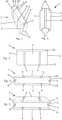
- 1 designates a first embodiment of a brick according to the invention.
- the brick 1 is essentially cuboid-shaped and has a first side 2 and a second side 3.
- the first side 2 and the second side 3 are adjacent, have a common edge and are essentially perpendicular to one another.
- a longitudinal connecting groove 4 which has an inwardly enlarged cross-section in the form of a dovetail.
- transverse connecting grooves 5 which also each have an inwardly enlarged cross-section in the form of a dovetail.
- the longitudinal connecting groove 4 and the transverse connecting grooves 5 are essentially parallel to one another.
- the brick 1 also has a third side 6 and a fourth side 7.
- the third side 6 is opposite the first side 2, runs parallel to it and has a longitudinal connecting groove 8 which has an inwardly enlarged cross-section in the form of a dovetail.
- the fourth side 7 is opposite the second side 3, runs parallel to it and has two transverse connecting grooves 9 which have an inwardly enlarged cross-section in the form of a dovetail.
- the longitudinal connecting grooves 4, 8 and the transverse connecting grooves 5, 9 are opposite each other. Furthermore, in two opposite edge areas of the brick 1, a fold 10 is arranged in an upper side and a tenon 11 is arranged in a lower side.
- the folds 10 and the tenons 11 run parallel to each other.
- the recess of the fold 10 essentially corresponds to the elevation of the tenon 11, so that two such bricks 1 can be placed one above the other. can be stacked without a cavity being created between the two bricks 1.
- the brick 1 is solid and has no continuous cavities.
- the longitudinal openings of the cross-connection grooves 5,9 are arranged completely in the folds 10, the depth of the cross-connection grooves 5,9 essentially corresponding to the extent of the fold 10 in the depth direction of the cross-connection grooves 5,9.
- a wall block 1 denotes a second embodiment of a brick according to the invention, with the same reference numbers as the same parts as in the Fig. 1 to 5 describe.
- side 7 is designed without grooves.
- Such a wall block 1 can be used, for example, as the innermost or outermost wall block of a wall composite, with the wall composite being limited to the inside or outside by the smooth side 7.
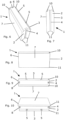
- Fig. 11 denotes a third embodiment of a brick according to the invention, with the same reference numbers as the same parts as in the Fig. 1 to 10 describe.
- the brick 1 has a further groove 12 in the underside, whereby, when several bricks 1 lie on top of each other, a cavity filled with air is delimited by the groove 12 and the top of the brick 1 arranged underneath. This cavity improves the insulating properties of a wall constructed from bricks 1 according to the invention.
- a brick according to the invention denotes a fourth embodiment of a brick according to the invention, with the same reference numbers being the same parts as in the Fig. 1 to 13 describe.
- the brick 1 has a groove 13 in the top that is perpendicular to the grooves 4, 5 and 9 and a fold 14 which is arranged transversely to the folds 10 and parallel to the groove 13.
- Such a brick 1 is designed to be connected to a further brick 1 arranged transversely to the brick 1, the pins 11 of the further brick 1 being arranged in the groove 13 and in the fold 14 in the connected state.
- Fig. 19 denotes a fifth embodiment of a brick according to the invention, with the same reference numbers as the same parts as in the Fig. 1 to 18 describe.
- the brick 1 has several cross-connection grooves 9.
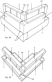
- FIG. 24a front view
- 24b side view
- 24c top view
- 24d front view
- the connecting dowel 15 comprises two dovetail-shaped sections 16, which are designed to be arranged in transverse connection or longitudinal connection grooves 4.5 of a brick 1.
- a first embodiment of a connecting dowel 15 according to the invention is shown in the Fig. 25a (front view), 25b (side view), 25c (top view) and 25d (perspective view) .
- the connecting dowel 15 has a plurality of grooves 17 in the longitudinal direction. These grooves 17 enable a better connection of the connecting dowel 15, which is grooved in this way, with a groove in a brick 1.
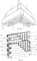
- FIG. 26 to 31 A three-shell wall constructed from bricks 1 according to the invention and connecting dowels 15 is shown schematically.
- the wall stones 1 correspond to those in the Fig. 1 to 23 bricks shown 1.
- the connecting dowels 15 correspond to those in Fig. 24 and 25 connecting dowels 15 shown.
- some reference numbers have been omitted.
- the pins 11 of the upper bricks 1 engage in the folds 10 of the lower bricks 1.
- the transverse connection or longitudinal connection grooves 4.5 of the individual bricks 1 form common cavities 18 into which connecting dowels 15 can be inserted in order to connect the bricks 1 to one another in a form-fitting manner.
- FIG. 31 is shown how the connecting dowels 15 are arranged in grooves 4,5,8,9 in order to connect the individual bricks 1 to one another.
- the Connecting dowels 15 can have different lengths and in particular the length of a connecting dowel 15 can correspond to the height of a brick 1 or the length of a connecting dowel 15 can be greater than the height of a brick 1, so that the brick 1 is not only connected to the brick 1 arranged next to it but also with the wall stone 1 below or above it.
Landscapes
- Engineering & Computer Science (AREA)
- Architecture (AREA)
- Civil Engineering (AREA)
- Structural Engineering (AREA)
- Life Sciences & Earth Sciences (AREA)
- Wood Science & Technology (AREA)
- Physics & Mathematics (AREA)
- Electromagnetism (AREA)
- Finishing Walls (AREA)
Description
Die Erfindung betrifft eine Mauer umfassend zumindest zwei Mauersteine, die jeweils einen im Wesentlichen quaderförmigen Körper aufweisen.The invention relates to a wall comprising at least two bricks, each of which has a substantially cuboid body.
Aus dem Stand der Technik sind verschiedene Holzziegel zum Aufbau von Wänden für Häuser und andere Gebäude bekannt, die unterschiedliche Formen und Verbindungsmöglichkeiten aufweisen. Insbesondere aufgrund der erstarkenden Umweltschutzbewegungen wird Holz als nachwachsender Rohstoff wieder stärker nachgefragt und auch als Ersatz für bereits bekannte Lösungen, bspw. Tonziegel, verwendet. Um die einzelnen Holzziegel zu verbinden, werden im Stand der Technik bspw. Nägel, Schrauben oder Dübel genutzt. Weiters sind Holzziegel bekannt, die eine spezielle Form aufweisen und miteinander im Mauerverbund fest verbunden werden können. Mauersteine, Ziegel und Blöcke mit Verbindungsmöglichkeit sind aus
Darüber hinaus sind Mauersteine der eingangs genannten Art bekannt, die eine Nut zur Verbindung mit einem anderen Mauerstein aufweisen. In einigen Fällen weist die Nut einen sich nach innen zumindest teilweise vergrößerten Querschnitt auf, wodurch eine formschlüssige Verbindung mit einer entsprechenden Feder oder einem Zapfen gebildet werden kann. Der Mauerstein kann bspw. auf der einen Seite eine Nut und auf der anderen Seite einen Zapfen aufweisen, sodass nebeneinanderliegende Mauersteine durch ein Einführen des Zapfens eines Mauersteines in die Nut eines anderen Mauersteines miteinander verbunden werden können. Nachteilig bei diesen Lösungen ist insbesondere, dass lediglich eine Reihe von Mauersteinen miteinander verbunden wird. Dadurch entstehen bei den Verbindungen Lücken, sodass die Mauer nicht dicht ist und ein ungewollter Luftaustausch zwischen der Außen- und der Innenseite stattfinden kann, wodurch die Dämmung der Mauer reduziert wird.In addition, bricks of the type mentioned are known which have a groove for connection to another brick. In some cases, the groove has a cross section that is at least partially enlarged inwards, whereby a positive connection can be formed with a corresponding spring or a pin. The brick can, for example, have a groove on one side and a tenon on the other side, so that adjacent bricks can be connected to one another by inserting the tenon of one brick into the groove of another brick. The particular disadvantage of these solutions is that only a row of bricks is connected to one another. This creates gaps in the connections, so that the wall is not tight and an unwanted exchange of air can take place between the outside and the inside, which reduces the insulation of the wall.
Es ist daher eine Aufgabe der Erfindung, eine Mauer mit Mauersteinen der eingangs genannten Art bereitzustellen, die einen Maueraufbau ermöglicht, der eine verbesserte Dämmwirkung aufweist.It is therefore an object of the invention to provide a wall with bricks of the type mentioned at the outset, which enables a wall structure that has an improved insulating effect.
Die Erfindung ist eine Mauer gemäß Anspruch 1.The invention is a wall according to
Ein für die erfindungsgemäße Mauer verwendeter Mauerstein ist im Wesentlichen quaderförmig und weist daher grundsätzlich sechs Seiten auf. Die Seiten können jeweils flach sein oder Nuten und sonstige Erhebungen bzw. Versenkungen aufweisen.A brick used for the wall according to the invention is essentially cuboid-shaped and therefore basically has six sides. The sides can each be flat or have grooves and other elevations or depressions.
Die Längsverbindungsnuten und die Querverbindungsnuten verlaufen durchgehend und weisen jeweils eine längs der Nut verlaufende Queröffnung ("Nutöffnung") sowie eine an der Ober- bzw. Unterseite des Mauersteins angeordnete Längsöffnung auf. Ein Verbindungselement, bspw. ein Holzdübel, kann durch die Längsöffnung in die Nut eingeführt werden, sodass eine formschlüssige Verbindung quer zum Nutverlauf geschaffen wird.The longitudinal connecting grooves and the cross-connecting grooves run continuously and each have a transverse opening (“groove opening”) running along the groove and a longitudinal opening arranged on the top and bottom of the brick. A connecting element, for example a wooden dowel, can be inserted into the groove through the longitudinal opening, so that a positive connection is created transversely to the course of the groove.
Die Erfindung sieht vor, dass der Mauerstein aus Vollholz, bevorzugt Fichtenholz, besteht. Hierbei ist der Mauerstein aus einem einzigen Stück Holz hergestellt, in welches die Längsverbindungsnut(en) bzw. die Querverbindungsnut(en) bevorzugt gefräst sind. Dadurch sind keine Verbindungen zwischen einzelnen Holzstücken, bspw. mithilfe von Schrauben oder Klebstoff, insbesondere Leim, nötig. Weiters entstehen bei einem derart hergestellten Mauerstein auch keine Fugen zwischen einzelnen Holzstücken, wodurch die Dichtheit des Mauersteines und der daraus gebauten Mauer verbessert wird. Der Mauerstein ist hierbei diffusionsoffen, sodass keine Dampfsperre benötigt wird. Bevorzugt ist vorgesehen, dass der Mauerstein aus unbehandeltem Holz besteht.The invention provides that the brick is made of solid wood, preferably spruce wood. Here, the brick is made from a single piece of wood, into which the longitudinal connecting groove(s) or the cross-connecting groove(s) are preferably milled. This means that no connections between individual pieces of wood, for example using screws or glue, especially glue, are necessary. Further With a brick made in this way, there are no joints between individual pieces of wood, which improves the tightness of the brick and the wall built from it. The brick is open to diffusion, so no vapor barrier is required. It is preferred that the brick is made of untreated wood.
Der Mauerstein ist bevorzugt massiv, also ohne zwischen zwei gegenüberliegenden Seiten durchgehende Hohlräume, bspw. Bohrungen, im Mauerstein ausgebildet. Hierbei wird kein zusätzlicher Dämmstoff benötigt. Alternativ kann der Mauerstein bevorzugt Öffnungen, insbesondere durchgehende Bohrungen, bspw. für elektrische Leitungen, aufweisen.The brick is preferably solid, i.e. formed in the brick without continuous cavities, for example holes, between two opposite sides. No additional insulation material is required. Alternatively, the brick can preferably have openings, in particular through holes, for example for electrical lines.
Weiters ist bevorzugt vorgesehen, dass die Längsverbindungsnut und die Querverbindungsnut sich im Wesentlichen senkrecht zu einer Unterseite und/oder Oberseite des Mauersteins erstrecken. Bei dieser Ausbildung wird es ermöglicht, mehrere Mauersteine übereinander zu schichten, wobei die Längs- bzw. Querverbindungsnuten mehrerer Mauersteine so angeordnet sind, dass hierdurch eine oder mehrere durchgehende Nuten gebildet werden, die zur Verbindung bzw. Stabilisierung der Mauer genutzt werden können.Furthermore, it is preferably provided that the longitudinal connecting groove and the transverse connecting groove extend essentially perpendicular to an underside and/or upper side of the brick. This design makes it possible to stack several bricks on top of each other, with the longitudinal or transverse connecting grooves of several bricks being arranged in such a way that one or more continuous grooves are formed, which can be used to connect or stabilize the wall.
Bevorzugt ist vorgesehen, dass in der der ersten Seite gegenüberliegenden dritten Seite eine weitere Längsverbindungsnut vorgesehen ist, wobei die beiden Längsverbindungsnuten einander bevorzugt im Wesentlichen gegenüberliegen. Diese Anordnung ermöglicht die Verbindung eines Mauersteins mit zwei weiteren Mauersteinen in Längsrichtung, wobei einer der weiteren Mauersteine auf der ersten Seite mit dem Mauerstein verbunden ist und der andere der weiteren Mauersteine auf der dritten Seite mit dem Mauerstein verbunden ist.It is preferably provided that a further longitudinal connecting groove is provided in the third side opposite the first side, wherein the two longitudinal connecting grooves preferably lie essentially opposite one another. This arrangement enables the connection of a brick with two other bricks in the longitudinal direction, with one of the other bricks on the is connected to the wall stone on the first side and the other of the other wall stones is connected to the wall stone on the third side.
Weiters ist bevorzugt vorgesehen, dass in der der zweiten Seite gegenüberliegenden vierten Seite eine weitere Querverbindungsnut vorgesehen ist, wobei die beiden Längsverbindungsnuten einander bevorzugt im Wesentlichen gegenüberliegen. Hierbei ist es möglich, eine mehrschalige Wand bereitzustellen, indem der Mauerstein auf der zweiten Seite mit einem ersten weiteren Mauerstein verbunden wird und auf der vierten Seite mit einem zweiten weiteren Mauerstein verbunden wird.Furthermore, it is preferably provided that a further transverse connecting groove is provided in the fourth side opposite the second side, with the two longitudinal connecting grooves preferably lying essentially opposite one another. It is possible to provide a multi-shell wall by connecting the brick on the second side to a first further brick and on the fourth side with a second further brick.
Bevorzugt ist vorgesehen, dass in der zweiten und/oder der vierten Seite zwei oder mehr Querverbindungsnuten vorgesehen sind. Bei dieser Anordnung kann auf einfache Art und Weise eine mehrschalige Wand mithilfe von versetzt angeordneten Mauersteinen aufgebaut werden kann. Durch das Vorhandensein von zumindest zwei Querverbindungsnuten wird die Verbindung eines Mauersteins mit zwei in einer weiteren Schicht daneben angeordneten Mauersteinen ermöglicht, sodass eine feste, stabile und möglichst wetterundurchlässige Mauer gebildet werden kann. Weiters ist bevorzugt vorgesehen, dass in der ersten und/oder der dritten Seite zwei oder mehr Längsverbindungsnuten vorgesehen sind. Diese Ausbildung erhöht die Flexibilität der Mauersteine, indem bspw. ein größerer Mauerstein mit zwei kleineren Mauersteinen verbunden werden kann. Hierbei ist im verbundenen Zustand bspw. ein erster kleinerer Mauerstein mit einer ersten Längsverbindungsnut verbunden und ein zweiter kleinerer Mauerstein mit einer zweiten Längsverbindungsnut.It is preferably provided that two or more cross-connecting grooves are provided in the second and/or the fourth side. With this arrangement, a multi-layered wall can be easily constructed using staggered bricks. The presence of at least two cross-connection grooves enables the connection of a brick with two bricks arranged next to it in a further layer, so that a solid, stable and weatherproof wall can be formed. Furthermore, it is preferably provided that two or more longitudinal connecting grooves are provided in the first and/or the third side. This design increases the flexibility of the bricks, for example by allowing a larger brick to be connected to two smaller bricks. In the connected state, for example, a first smaller brick is connected to a first longitudinal connecting groove and a second smaller brick is connected to a second longitudinal connecting groove.
Bevorzugt ist vorgesehen, dass die erste Seite und die dritte Seite sowie die zweite Seite und die vierte Seite jeweils im Wesentlichen parallel zueinander angeordnet sind.It is preferably provided that the first side and the third side as well as the second side and the fourth side are each arranged essentially parallel to one another.
Bei einer bevorzugten Ausbildung ist vorgesehen, dass sich der Querschnitt der Längsverbindungsnut und/oder der Querverbindungsnut von der Nutöffnung weg kontinuierlich verbreitert. Besonders bevorzugt ist vorgesehen, dass die Längsverbindungsnut und/oder die Querverbindungsnut als Schwalbenschwanznut ausgebildet ist. Eine derartige Nutform hat den Vorteil, dass ein in der Nut angeordnetes, der Nutform entsprechendes Verbindungselement, bspw. ein Holzdübel, formschlüssig fest in der Nut gehalten wird. Weiters gibt es hierbei lediglich einen Platz für das Verbindungselement, wodurch beim Einführen des Verbindungselements die zu verbindenden Mauersteine ohne weiteres Zutun in die richtige Position zueinander gebracht werden.In a preferred embodiment, it is provided that the cross section of the longitudinal connecting groove and/or the transverse connecting groove widens continuously away from the groove opening. It is particularly preferred that the longitudinal connecting groove and/or the transverse connecting groove is designed as a dovetail groove. Such a groove shape has the advantage that a connecting element arranged in the groove and corresponding to the groove shape, for example a wooden dowel, is held firmly in the groove in a form-fitting manner. Furthermore, there is only one place for the connecting element, which means that when the connecting element is inserted, the bricks to be connected are brought into the correct position relative to one another without any further action.
Weiters ist vorgesehen, dass in zumindest einem Randbereich des Mauersteins ein Falz angeordnet ist. Der Mauerstein weist hierbei eine Stufe in zumindest einem, bevorzugt zwei gegenüberliegenden Randbereichen auf. Die Stufe wird durch zwei Begrenzungen gebildet, die bevorzugt im Wesentlichen senkrecht zueinanderstehen. Bevorzugt sind, wenn zwei Falze vorgesehen sind, diese im Wesentlichen parallel zueinander. Der Falz ist hierbei zwischen zwei Seiten des im Wesentlichen quaderförmigen Mauersteins angeordnet, bevorzugt der Oberseite und einer weiteren Seite, bspw. der zweiten und/oder vierten Seite. Dieser Falz kann genutzt werden, um eine formschlüssige Verbindung in Querrichtung zum Falzverlauf mit einem anderen Mauerstein zu bilden.Furthermore, it is provided that a fold is arranged in at least one edge region of the brick. The brick has a step in at least one, preferably two, opposite edge areas. The step is formed by two boundaries, which are preferably essentially perpendicular to one another. If two folds are provided, they are preferably essentially parallel to one another. The fold is here arranged between two sides of the essentially cuboid brick, preferably the top and another side, for example the second and/or fourth side. This fold can be used to form a positive connection with another brick in the transverse direction of the fold.
Hierzu ist bevorzugt vorgesehen, dass der Mauerstein an einer Oberseite in zwei gegenüberliegenden Randbereichen jeweils einen Falz aufweist und an der Unterseite in diesen zwei gegenüberliegenden Randbereichen jeweils einen Zapfen. Die Zapfen sind derart ausgebildet, dass sie in die Falze eines anderen Mauersteins, der die gleiche Falz-Zapfen Kombination aufweist, eingreifen können. Dadurch kann die Unterseite eines ersten Mauersteins in die Oberseite eines gleichartigen zweiten Mauersteins eingreifen und hierdurch verbunden werden. Bevorzugt sind die Höhe der Zapfen und die Tiefe der Falze im Wesentlichen gleich groß, sodass übereinanderliegende Steine gleicher Art bündig abschließen. Alternativ kann vorgesehen sein, dass die Höhe der Zapfen größer ist als die Tiefe der Falze, wodurch zwischen übereinanderliegenden Steinen ein Hohlraum entsteht, in welchem bspw. Luft angeordnet ist. Solch ein Hohlraum erhöht die Dämmwirkung der durch die Mauersteine gebildeten Mauer.For this purpose, it is preferably provided that the brick has a fold on one upper side in two opposite edge regions and a tenon on the underside in each of these two opposite edge regions. The tenons are designed in such a way that they can engage in the folds of another brick that has the same rebate-tenon combination. This allows the underside of a first brick to engage with the top of a similar second brick and thereby be connected. Preferably, the height of the tenons and the depth of the folds are essentially the same size, so that stones of the same type lying on top of each other are flush. Alternatively, it can be provided that the height of the tenons is greater than the depth of the folds, which creates a cavity between stones lying one on top of the other, in which, for example, air is arranged. Such a cavity increases the insulating effect of the wall formed by the bricks.
Der bzw. die Falze ist bzw. sind bevorzugt derart angeordnet, dass die Längsöffnung einer Querverbindungsnut oder einer Längsverbindungsnut, bevorzugt vollständig, im Falz angeordnet ist. Die Nutöffnungen der Querverbindungsnut(en) bzw. der Längsverbindungsnut(en) münden in den entsprechenden Falz und sind hierbei direkt an der Außenseite des Mauersteins angeordnet, sodass eine einfache Verbindung mit einem anderen Mauerstein bspw. mithilfe eines Verbindungsdübels möglich ist. Die Längsöffnung erstreckt sich bevorzugt in einer zur Oberfläche des Mauersteins parallelen Fläche.The fold or folds is or are preferably arranged such that the longitudinal opening of a transverse connecting groove or a longitudinal connecting groove is arranged, preferably completely, in the fold. The groove openings of the transverse connection groove(s) or the longitudinal connection groove(s) open into the corresponding fold and are arranged directly on the outside of the brick, so that a simple connection to another brick is possible, for example using a connecting dowel. The longitudinal opening preferably extends in a surface parallel to the surface of the brick.
Bevorzugt entspricht die Tiefe der Querverbindungsnut bzw. der Längsverbindungsnut im Wesentlichen der Ausdehnung des Falzes in der Tiefenrichtung der Nut. Hierbei liegt ein in der Nut angeordneter und darüber hinausragender Verbindungsdübel an der zur Tiefenrichtung der Nut senkrechten Begrenzung des Falzes an, sodass die Verbindung zwischen der Nut und dem Verbindungsdübel stabilisiert wird.Preferably, the depth of the transverse connecting groove or the longitudinal connecting groove essentially corresponds to the extent of the Fold in the depth direction of the groove. Here, a connecting dowel arranged in the groove and protruding beyond it lies against the boundary of the fold perpendicular to the depth direction of the groove, so that the connection between the groove and the connecting dowel is stabilized.
Bevorzugt ist ein weiterer Falz in einem Randbereich des Mauersteins angeordnet, der quer zu dem anderen Falz verläuft. Falls drei Randbereiche des Mauersteins einen Falz aufweisen, wird in der Draufsicht durch die Falze eine U-Form gebildet.A further fold is preferably arranged in an edge region of the brick, which runs transversely to the other fold. If three edge areas of the brick have a fold, the folds form a U-shape when viewed from above.
Weiters weist der Mauerstein bevorzugt eine Nut an der Oberseite auf, die senkrecht zu der Längsverbindungsnut und der Querverbindungsnut verläuft. Besonders bevorzugt verläuft die Nut im Wesentlichen parallel zu einem an der Oberseite des Mauersteins angeordneten Falz. Weiters ist die Nut bevorzugt durchgehend ausgebildet. In diese Nut kann bspw. ein quer zu einem ersten Mauerstein angeordneter zweiter Mauerstein angeordnet werden, um eine Verbindung herzustellen.Furthermore, the brick preferably has a groove on the top, which runs perpendicular to the longitudinal connecting groove and the transverse connecting groove. Particularly preferably, the groove runs essentially parallel to a fold arranged on the top of the brick. Furthermore, the groove is preferably formed continuously. For example, a second brick arranged transversely to a first brick can be arranged in this groove in order to establish a connection.
Bevorzugt ist vorgesehen, dass die zumindest eine Längsverbindungsnut und die zumindest eine Querverbindungsnut im Wesentlichen den gleichen Querschnitt aufweisen. Dies ermöglicht die Verwendung von gleichen Verbindungsstücken, um sowohl in Längsverbindungsnuten als auch in Querverbindungsnuten eingreifen zu können.It is preferably provided that the at least one longitudinal connecting groove and the at least one transverse connecting groove have essentially the same cross section. This enables the use of the same connecting pieces in order to be able to engage in both longitudinal connecting grooves and transverse connecting grooves.
Die Längsverbindungsnut und/oder die Querverbindungsnut weist bevorzugt eine Fase an der Längsöffnung auf, um ein Einführen eines Verbindungselements, bspw. eines Holzdübels, zu erleichtern.The longitudinal connecting groove and/or the transverse connecting groove preferably has a chamfer on the longitudinal opening in order to allow insertion of a connecting element, for example a wooden dowels, to make it easier.
Die Längsverbindungsnut und/oder die Querverbindungsnut weisen bevorzugt einen über die Länge der Nut im Wesentlichen gleichbleibenden Querschnitt auf, um ein Einführen eines Holzdübels oder einer Feder zu ermöglichen bzw. zu erleichtern.The longitudinal connecting groove and/or the transverse connecting groove preferably have a cross-section that is essentially constant over the length of the groove in order to enable or facilitate the insertion of a wooden dowel or a spring.
Bei einer bevorzugten Ausführungsform weist zumindest eine Seite des Mauersteins ein Wetterprofil auf, welches im Querschnitt mehrere Vorsprünge umfasst, die dazu dienen, um Wasser besser abzuleiten.In a preferred embodiment, at least one side of the brick has a weather profile which, in cross section, includes several projections which serve to better drain water.
Der Mauerstein weist weiters bevorzugt an seiner Unterseite eine weitere, bevorzugt durchgehende, Nut auf. Im mit anderen Mauersteinen verbundenen Zustand dient diese Nut als Luftvolumen, welches die Dämmung der Wand weiter verbessert.The brick preferably also has a further, preferably continuous, groove on its underside. When connected to other bricks, this groove serves as an air volume, which further improves the insulation of the wall.
Die Nuten, insbesondere die Querverbindungsnut(en) sowie die Längsverbindungsnut(en), sowie ggf. der Falz und weitere Nuten sind bevorzugt durch Fräsen hergestellt.The grooves, in particular the transverse connecting groove(s) and the longitudinal connecting groove(s), as well as possibly the fold and other grooves are preferably produced by milling.
Weiters ist bevorzugt vorgesehen, dass der Querschnitt des zumindest einen Verbindungsdübels im Wesentlichen dem Querschnitt der Längsverbindungsnut und/oder der Querverbindungsnut entspricht.Furthermore, it is preferably provided that the cross section of the at least one connecting dowel essentially corresponds to the cross section of the longitudinal connecting groove and/or the transverse connecting groove.
Der bzw. die Verbindungsdübel weist bzw. weisen bevorzugt zumindest eine Länge auf, die der Höhe des Mauersteins entspricht. Besonders bevorzugt ist die Länge des Verbindungsdübels größer als die Höhe des Mauersteins, sodass auch übereinander angeordnete Mauersteine einfach mithilfe eines Verbindungsdübels miteinander verbunden werden können. Die Länge des Verbindungsdübels entspricht bevorzugt zumindest der 1,5-fachen, besonders bevorzugt der zumindest 2-fachen, insbesondere der zumindest 2,5-fachen Länge der Längs- bzw. Querverbindungsnut eines Mauersteins. Dies ermöglicht eine stabile Verbindung der Mauersteine miteinander.The connecting dowel(s) preferably has at least a length that corresponds to the height of the brick. Particularly preferably, the length of the connecting dowel is greater than the height of the brick, so that bricks arranged one above the other are also easy can be connected to each other using a connecting dowel. The length of the connecting dowel preferably corresponds to at least 1.5 times, particularly preferably at least 2 times, in particular at least 2.5 times the length of the longitudinal or transverse connecting groove of a brick. This enables a stable connection of the bricks to one another.
Bevorzugt ist vorgesehen, dass der zumindest eine Mauerstein und der zumindest eine Verbindungsdübel aus unterschiedlichen Holzarten gefertigt sind. Besonders bevorzugt ist hierbei vorgesehen, dass der Mauerstein aus Fichtenholz und der Verbindungsdübel aus Buchenholz besteht. Durch diese Kombination ergibt sich eine besonders gute Verbindung zwischen dem Mauerstein und dem Verbindungsdübel. Alternativ ist vorgesehen, dass der Mauerstein und der Verbindungsdübel aus der gleichen Holzart gefertigt sind.It is preferably provided that the at least one brick and the at least one connecting dowel are made from different types of wood. It is particularly preferred that the brick is made of spruce wood and the connecting dowel is made of beech wood. This combination results in a particularly good connection between the brick and the connecting dowel. Alternatively, it is envisaged that the brick and the connecting dowel are made of the same type of wood.
Weiters ist bevorzugt vorgesehen, dass der Verbindungsdübel derart ausgebildet ist, dass der erste Mauerstein und der zweite Mauerstein einander im verbundenen Zustand berühren. Der Verbindungsdübel ist in dieser Ausführungsform bspw. derart ausgebildet, dass die jeweils in die Nuten, insbesondere Längs- bzw. Querverbindungsnuten, einführbaren Bereiche direkt aneinander angrenzen. Beispielsweise weist der Verbindungsdübel im Querschnitt zwei direkt aneinander anschließende Schwalbenschwänze auf.Furthermore, it is preferably provided that the connecting dowel is designed such that the first brick and the second brick touch each other in the connected state. In this embodiment, the connecting dowel is designed, for example, in such a way that the areas that can be inserted into the grooves, in particular longitudinal or transverse connecting grooves, directly adjoin one another. For example, the connecting dowel has two directly adjacent dovetails in cross section.
Weiters ist bevorzugt vorgesehen, dass der Verbindungsdübel in Längsrichtung Rillen aufweist (geriffelt ist), wodurch ein eventuell zur Verbindung verwendeter Klebstoff, bspw. Leim, besser am Dübel haften bleibt.Furthermore, it is preferably provided that the connecting dowel has grooves (ribbed) in the longitudinal direction, so that any adhesive used for the connection, for example glue, sticks better to the dowel.
Weiters weist der Verbindungsdübel bevorzugt eine Fase auf, die ein Einführen des Verbindungsdübels in die entsprechende Nut des Mauersteins erleichtert.Furthermore, the connecting dowel preferably has a chamfer, which makes it easier to insert the connecting dowel into the corresponding groove in the brick.
Eine besondere Ausführungsform betrifft eine Mauer, bei welcher Verbindungsdübel in Längs- bzw. Querverbindungsnuten zumindest eines Mauersteins angeordnet sind. Hierbei ist bevorzugt vorgesehen, dass die Verbindungsdübel mithilfe von Holzleim, insbesondere Kaseinleim, in den Längs- bzw. Querverbindungsnuten befestigt sind.A special embodiment relates to a wall in which connecting dowels are arranged in longitudinal or transverse connecting grooves of at least one brick. It is preferably provided that the connecting dowels are fastened in the longitudinal or transverse connecting grooves using wood glue, in particular casein glue.
Bevorzugt ist eine zwei-, drei- oder mehrschalige Mauer vorgesehen, bei welcher die einzelnen Schalen mithilfe der Querverbindungsnuten miteinander verbunden sind.A two-, three- or multi-shell wall is preferably provided, in which the individual shells are connected to one another using the cross-connection grooves.
Die Erfindung wird nachfolgend anhand eines in der Zeichnung schematisch dargestellten Ausführungsbeispiels näher erläutert. In dieser zeigen
In den
In den
In den
In den
In den
In den
In den
In den
Claims (5)
- Wall, comprising at least two bricks (1), each of which comprises a substantially cuboid body, which has a longitudinal connecting groove (4) in a first side (2) with a cross-section that is at least partially enlarged inwards, wherein two or more cross connecting grooves (5), which are substantially parallel to the longitudinal connecting groove (4), with a cross-section that is at least partially enlarged inwards are provided in a second side (3) adjacent to the first side (2), as well as at least one connecting dowel (15), characterized in that the bricks (1) are made of solid wood and the connecting dowel (15) engages in the cross connecting groove (5) of a first brick (1) and at the same time engages in the cross-connecting groove (5) of a second brick (1), whereby the first brick (1) and the second brick (1) are connected to one another, wherein the connecting dowel (15) is designed such that the first brick (1) and the second brick (1) touch each other.
- Wall according to claim 1, characterized in that the longitudinal connecting groove (4) and the cross connecting groove (5) extend essentially perpendicular to a bottom side and/or a top side of the brick (1).
- Wall according to claim 1 or 2, characterized in that the longitudinal connecting groove (4) and/or the cross connecting groove (5) is designed as a dovetail groove.
- Wall according to one of claims 1 to 3, characterized in that a fold (10) is arranged in at least one edge region.
- Wall according to one of claims 1 to 4, characterized in that the longitudinal connecting groove (4) and the cross connecting groove (5) have essentially the same cross section.
Applications Claiming Priority (1)
| Application Number | Priority Date | Filing Date | Title |
|---|---|---|---|
| ATA50831/2020A AT524296B1 (en) | 2020-09-29 | 2020-09-29 | brick |
Publications (3)
| Publication Number | Publication Date |
|---|---|
| EP3974594A1 EP3974594A1 (en) | 2022-03-30 |
| EP3974594C0 EP3974594C0 (en) | 2024-03-27 |
| EP3974594B1 true EP3974594B1 (en) | 2024-03-27 |
Family
ID=77998697
Family Applications (1)
| Application Number | Title | Priority Date | Filing Date |
|---|---|---|---|
| EP21199071.8A Active EP3974594B1 (en) | 2020-09-29 | 2021-09-27 | Wall |
Country Status (2)
| Country | Link |
|---|---|
| EP (1) | EP3974594B1 (en) |
| AT (1) | AT524296B1 (en) |
Families Citing this family (1)
| Publication number | Priority date | Publication date | Assignee | Title |
|---|---|---|---|---|
| CN114775837B (en) * | 2022-04-29 | 2024-03-22 | 金松果新材料科技有限公司 | Modular wall and method of assembling the same |
Family Cites Families (10)
| Publication number | Priority date | Publication date | Assignee | Title |
|---|---|---|---|---|
| GB191509474A (en) * | 1915-06-29 | 1916-06-29 | James Thomas South | Improvements in Interlocking Bricks. |
| ES2009864A6 (en) * | 1987-09-25 | 1989-10-16 | M K Holding S A | Construction of facings, walls and partitions of massive or reconstituted wood, especially for buildings, and blocks used in this construction. |
| DE19835482A1 (en) * | 1998-08-07 | 2000-02-10 | Kurt Pfeifer | Wood block construction system uses scrap wood and offcuts to shape into interlocking blocks for outer and inner walls |
| NZ503003A (en) * | 2000-02-22 | 2001-05-25 | Katherine Gail Duncan | Building module consisting of panels spaced by framing members that project out and interlock with adjacent members when panels assembled |
| DE102010045023B4 (en) * | 2010-09-10 | 2012-09-20 | Ws Holzfertigung Gmbh | Connection system for building a furniture body, and furniture body and method for creating a miter joint |
| US20130205705A1 (en) * | 2012-02-10 | 2013-08-15 | Augustin Bilka | Masonry block, link, and method of interlocking |
| CN203795698U (en) * | 2014-03-12 | 2014-08-27 | 山东惠友木艺有限公司 | Novel hollow wood brick |
| BE1025147B1 (en) * | 2017-09-13 | 2018-11-13 | N.U.D. Bvba | Building block |
| BE1025942B1 (en) * | 2018-01-17 | 2019-08-21 | MI CASA nv | METHOD FOR CONNECTING TWO BARS |
| AT16505U1 (en) * | 2018-10-15 | 2019-11-15 | Jakob Koch Daniel | Natural composite solid wood tile |
-
2020
- 2020-09-29 AT ATA50831/2020A patent/AT524296B1/en active
-
2021
- 2021-09-27 EP EP21199071.8A patent/EP3974594B1/en active Active
Also Published As
| Publication number | Publication date |
|---|---|
| AT524296B1 (en) | 2023-04-15 |
| EP3974594A1 (en) | 2022-03-30 |
| EP3974594C0 (en) | 2024-03-27 |
| AT524296A1 (en) | 2022-04-15 |
Similar Documents
| Publication | Publication Date | Title |
|---|---|---|
| EP2821191B1 (en) | Wooden panel element | |
| WO2007128255A1 (en) | Wooden lattice beam for construction | |
| EP1734200A1 (en) | Wall element for a building and a composite wood panel | |
| EP0275938B1 (en) | Construction element for formwork, and permanent formwork constituted by such an element | |
| EP3974594B1 (en) | Wall | |
| EP0744507A1 (en) | Building module for erecting plane constructions, especially walls | |
| DE202004014003U1 (en) | Construction module | |
| DE19739787C2 (en) | Log sauna | |
| EP0970284B1 (en) | Frame section to be used as a modular structural element for buildings, method for the production thereof | |
| WO1999066148A1 (en) | Wall-, ceiling- and roof-building element | |
| AT502571B1 (en) | INSTALLATION BOX | |
| DE102006022871B4 (en) | Method for producing a thermally insulating wall and thermally insulating wall | |
| AT390466B (en) | Structural element for erecting walls | |
| DE69105717T2 (en) | CONSTRUCTION SYSTEM FOR BUILDING WALLS AND METHOD FOR BUILDING WALLS WITH THIS SYSTEM. | |
| EP1020584B1 (en) | Building block | |
| EP0440177A1 (en) | Shuttering for concrete construction | |
| DE3730679C2 (en) | ||
| DE202013008960U1 (en) | Arrangement of building elements made of EPS to form walls | |
| DE2035560C (en) | Plate-shaped component | |
| DE19623659C2 (en) | Brick wall made of at least two prefabricated brick wall elements | |
| DE19549178A1 (en) | Constructional kit with building blocks | |
| AT504866B1 (en) | WALL FOR A CONSTRUCTION WORK | |
| DE29619552U1 (en) | Plate-like component made of foam, in particular for use in a bath panel | |
| DE29520712U1 (en) | Kit with bricks | |
| DE2630316A1 (en) | PRE-FABRICATED COMPONENTS FOR THE CREATION OF WALLS |
Legal Events
| Date | Code | Title | Description |
|---|---|---|---|
| PUAI | Public reference made under article 153(3) epc to a published international application that has entered the european phase |
Free format text: ORIGINAL CODE: 0009012 |
|
| STAA | Information on the status of an ep patent application or granted ep patent |
Free format text: STATUS: THE APPLICATION HAS BEEN PUBLISHED |
|
| AK | Designated contracting states |
Kind code of ref document: A1 Designated state(s): AL AT BE BG CH CY CZ DE DK EE ES FI FR GB GR HR HU IE IS IT LI LT LU LV MC MK MT NL NO PL PT RO RS SE SI SK SM TR |
|
| STAA | Information on the status of an ep patent application or granted ep patent |
Free format text: STATUS: REQUEST FOR EXAMINATION WAS MADE |
|
| 17P | Request for examination filed |
Effective date: 20220928 |
|
| RBV | Designated contracting states (corrected) |
Designated state(s): AL AT BE BG CH CY CZ DE DK EE ES FI FR GB GR HR HU IE IS IT LI LT LU LV MC MK MT NL NO PL PT RO RS SE SI SK SM TR |
|
| GRAP | Despatch of communication of intention to grant a patent |
Free format text: ORIGINAL CODE: EPIDOSNIGR1 |
|
| STAA | Information on the status of an ep patent application or granted ep patent |
Free format text: STATUS: GRANT OF PATENT IS INTENDED |
|
| INTG | Intention to grant announced |
Effective date: 20230823 |
|
| GRAJ | Information related to disapproval of communication of intention to grant by the applicant or resumption of examination proceedings by the epo deleted |
Free format text: ORIGINAL CODE: EPIDOSDIGR1 |
|
| GRAL | Information related to payment of fee for publishing/printing deleted |
Free format text: ORIGINAL CODE: EPIDOSDIGR3 |
|
| GRAS | Grant fee paid |
Free format text: ORIGINAL CODE: EPIDOSNIGR3 |
|
| STAA | Information on the status of an ep patent application or granted ep patent |
Free format text: STATUS: REQUEST FOR EXAMINATION WAS MADE |
|
| INTC | Intention to grant announced (deleted) | ||
| GRAP | Despatch of communication of intention to grant a patent |
Free format text: ORIGINAL CODE: EPIDOSNIGR1 |
|
| STAA | Information on the status of an ep patent application or granted ep patent |
Free format text: STATUS: GRANT OF PATENT IS INTENDED |
|
| GRAA | (expected) grant |
Free format text: ORIGINAL CODE: 0009210 |
|
| STAA | Information on the status of an ep patent application or granted ep patent |
Free format text: STATUS: THE PATENT HAS BEEN GRANTED |
|
| INTG | Intention to grant announced |
Effective date: 20240219 |
|
| AK | Designated contracting states |
Kind code of ref document: B1 Designated state(s): AL AT BE BG CH CY CZ DE DK EE ES FI FR GB GR HR HU IE IS IT LI LT LU LV MC MK MT NL NO PL PT RO RS SE SI SK SM TR |
|
| REG | Reference to a national code |
Ref country code: GB Ref legal event code: FG4D Free format text: NOT ENGLISH |
|
| REG | Reference to a national code |
Ref country code: CH Ref legal event code: EP |
|
| REG | Reference to a national code |
Ref country code: DE Ref legal event code: R096 Ref document number: 502021003088 Country of ref document: DE |
|
| REG | Reference to a national code |
Ref country code: IE Ref legal event code: FG4D Free format text: LANGUAGE OF EP DOCUMENT: GERMAN |
|
| U01 | Request for unitary effect filed |
Effective date: 20240402 |
|
| U07 | Unitary effect registered |
Designated state(s): AT BE BG DE DK EE FI FR IT LT LU LV MT NL PT SE SI Effective date: 20240411 |
|
| PG25 | Lapsed in a contracting state [announced via postgrant information from national office to epo] |
Ref country code: GR Free format text: LAPSE BECAUSE OF FAILURE TO SUBMIT A TRANSLATION OF THE DESCRIPTION OR TO PAY THE FEE WITHIN THE PRESCRIBED TIME-LIMIT Effective date: 20240628 |
|
| PG25 | Lapsed in a contracting state [announced via postgrant information from national office to epo] |
Ref country code: HR Free format text: LAPSE BECAUSE OF FAILURE TO SUBMIT A TRANSLATION OF THE DESCRIPTION OR TO PAY THE FEE WITHIN THE PRESCRIBED TIME-LIMIT Effective date: 20240327 Ref country code: RS Free format text: LAPSE BECAUSE OF FAILURE TO SUBMIT A TRANSLATION OF THE DESCRIPTION OR TO PAY THE FEE WITHIN THE PRESCRIBED TIME-LIMIT Effective date: 20240627 |
|
| PG25 | Lapsed in a contracting state [announced via postgrant information from national office to epo] |
Ref country code: RS Free format text: LAPSE BECAUSE OF FAILURE TO SUBMIT A TRANSLATION OF THE DESCRIPTION OR TO PAY THE FEE WITHIN THE PRESCRIBED TIME-LIMIT Effective date: 20240627 Ref country code: NO Free format text: LAPSE BECAUSE OF FAILURE TO SUBMIT A TRANSLATION OF THE DESCRIPTION OR TO PAY THE FEE WITHIN THE PRESCRIBED TIME-LIMIT Effective date: 20240627 Ref country code: HR Free format text: LAPSE BECAUSE OF FAILURE TO SUBMIT A TRANSLATION OF THE DESCRIPTION OR TO PAY THE FEE WITHIN THE PRESCRIBED TIME-LIMIT Effective date: 20240327 Ref country code: GR Free format text: LAPSE BECAUSE OF FAILURE TO SUBMIT A TRANSLATION OF THE DESCRIPTION OR TO PAY THE FEE WITHIN THE PRESCRIBED TIME-LIMIT Effective date: 20240628 |