EP3974250B1 - Dämpfersystem für aufhängung eines fahrzeugsitzes - Google Patents
Dämpfersystem für aufhängung eines fahrzeugsitzes Download PDFInfo
- Publication number
- EP3974250B1 EP3974250B1 EP21198926.4A EP21198926A EP3974250B1 EP 3974250 B1 EP3974250 B1 EP 3974250B1 EP 21198926 A EP21198926 A EP 21198926A EP 3974250 B1 EP3974250 B1 EP 3974250B1
- Authority
- EP
- European Patent Office
- Prior art keywords
- suspension
- damper
- link
- base
- neutral position
- Prior art date
- Legal status (The legal status is an assumption and is not a legal conclusion. Google has not performed a legal analysis and makes no representation as to the accuracy of the status listed.)
- Active
Links
Images


Classifications
-
- B—PERFORMING OPERATIONS; TRANSPORTING
- B60—VEHICLES IN GENERAL
- B60N—SEATS SPECIALLY ADAPTED FOR VEHICLES; VEHICLE PASSENGER ACCOMMODATION NOT OTHERWISE PROVIDED FOR
- B60N2/00—Seats specially adapted for vehicles; Arrangement or mounting of seats in vehicles
- B60N2/50—Seat suspension devices
- B60N2/506—Seat guided by rods
- B60N2/508—Scissors-like structure
-
- B—PERFORMING OPERATIONS; TRANSPORTING
- B60—VEHICLES IN GENERAL
- B60N—SEATS SPECIALLY ADAPTED FOR VEHICLES; VEHICLE PASSENGER ACCOMMODATION NOT OTHERWISE PROVIDED FOR
- B60N2/00—Seats specially adapted for vehicles; Arrangement or mounting of seats in vehicles
- B60N2/50—Seat suspension devices
- B60N2/502—Seat suspension devices attached to the base of the seat
-
- B—PERFORMING OPERATIONS; TRANSPORTING
- B60—VEHICLES IN GENERAL
- B60N—SEATS SPECIALLY ADAPTED FOR VEHICLES; VEHICLE PASSENGER ACCOMMODATION NOT OTHERWISE PROVIDED FOR
- B60N2/00—Seats specially adapted for vehicles; Arrangement or mounting of seats in vehicles
- B60N2/50—Seat suspension devices
- B60N2/505—Adjustable suspension including height adjustment
-
- B—PERFORMING OPERATIONS; TRANSPORTING
- B60—VEHICLES IN GENERAL
- B60N—SEATS SPECIALLY ADAPTED FOR VEHICLES; VEHICLE PASSENGER ACCOMMODATION NOT OTHERWISE PROVIDED FOR
- B60N2/00—Seats specially adapted for vehicles; Arrangement or mounting of seats in vehicles
- B60N2/50—Seat suspension devices
- B60N2/52—Seat suspension devices using fluid means
- B60N2/522—Seat suspension devices using fluid means characterised by dampening means
Definitions
- Vehicle seats may sometimes include suspensions that allow the seats to move relative to a support frame or relative to a cab in which the seats are installed.
- suspensions that allow the seats to move relative to a support frame or relative to a cab in which the seats are installed.
- damper systems for the suspensions including to slow the movement of the seats, as guided by the suspensions, in response to ground contours, changes in loading on the seats, and so on.
- US 7,413,158 discloses a shock-absorbing platform that includes a bottom plate and a top plate j oined to one another along at least two sides by elongate rigid links that enable the plates to remain in parallel relation to one another as the plates are displaced responsive to externally-imparted forces.
- An air spring resists relative vertical motion between the bottom and top plates as external forces are applied to the platform.
- a shock-absorbing damper damps the natural oscillation of the air spring.
- the resistance presented by the air spring is adjustable through an inlet and outlet port in fluid communication with a remote source of air under pressure.
- a seat bottom includes arched leaf springs that supplant the air spring to increase the range of relative movement between the top and bottom plates and to lower the profile of the seat bottom.
- US 2020/108751 discloses a vehicle seat having a vehicle seat underbody, comprising: a base plate, a side horizontal suspension, a rolling suspension comprising a rod element rotatably mounted with respect to the side horizontal suspension; a scissors-type frame having a first swing and a second swing, The first swing is connected by a first slide element to the rod element and the second swing is connected by a second slide element to the rod element. The first swing is connected to the first slide element and the second swing is connected to the second slide element.
- the vehicle seat further comprises a first element carrier, a lengthwise horizontal suspension, and a first spring element, which is connected on the one hand to the first element carrier and on the other hand to the base plate or one of the swings.
- the damper system according to the invention comprises the features of claim 1.
- Some aspects of the invention can provide a damper system for a suspension for a vehicle seat, the suspension being configured to move upward and downward relative to a neutral position.
- a suspension for a vehicle seat to move a seat portion of the vehicle seat relative to a neutral position.
- the suspension can include a damping linkage and a damper.
- the damping linkage can be coupled between a base of the suspension and a suspension member that is configured to support the seat portion of the vehicle seat relative to the base.
- the damper can be coupled between the base and the damping linkage.
- the damping linkage can include a first damping link, a second damping link, and an intermediate damping link.
- the first damping link can be coupled between the base and the damper.
- the second damping link coupled between the suspension member and the intermediate damping link.
- the intermediate damping link can be pivotally coupled between the second damping link and the damper.
- the first, second, and intermediate damping links can cooperate to actuate the damper in a first direction when the suspension is moved in an upward direction away from the neutral position and when the suspension is moved in a downward direction away from the neutral position.
- a damper can be configured to provide a first damping force profile when actuated in a first direction and a second damping force profile when actuated in an opposing second direction.
- the first damping force profile can provide a greater damping force relative to the second damping force profile.
- a suspension member can be a first scissor link in a scissor linkage.
- the first scissor link and a second scissor link of the scissor linkage can pivot relative to each other during upward and downward movement of a suspension relative to a neutral position, so that the first scissor link moves a damper via a damping linkage.
- a first damping link can be pivotally coupled to a base at a first end of the first damping link.
- a first damping link can include a protrusion extending from a first end.
- the protrusion can be configured to engage a portion of a base to limit rotation of the first damping link, relative to the base, at a predetermined position.
- a suspension for a vehicle seat to move a seat portion of the vehicle seat upward and downward relative to a neutral position.
- the suspension can include a damper configured to provide damping primarily when moved in a first direction corresponding to extension or compression of the damper, and a linkage secured to the damper and configured to be secured between a support member of the suspension and a base of the suspension.
- the linkage can be configured to cause the damper to move in the first direction when the seat portion is moved upward from the neutral position and when the seat portion is moved downward from the neutral position.
- a linkage can be configured to cause the damper to move in a second direction opposite a first direction when the suspension is moved upward toward the neutral position and when the suspension is moved downward toward the neutral position.
- a linkage includes a base link, an intermediate link, and a suspension link.
- the base link can be configured to be secured to a base at a first end and be pivotally secured to a damper and to the intermediate link at a second end.
- the intermediate link cab be pivotally secured to the damper and to the base link at a first end and be pivotally secured to the suspension link at a second end.
- the suspension link can be pivotally secured to the intermediate link at a first end and be configured to be secured to a movable suspension member of a suspension at a second end.
- a first end of a base link can be configured to be rigidly secured to a base and a second end of the base link can include an arcuate slot that slidably receives a pin to secure a damper and an intermediate link.
- a support member of a suspension can be a scissor link of a scissor linkage.
- a damper can be configured to provide a first damping profile when moved in a first direction corresponding to extension or compression of the damper and to provide a second damping profile when moved in a second direction opposite the first direction.
- the first damping profile can be different from the second damping profile.
- a linkage when a suspension is in a neutral position, can be configured to place a damper in a minimum extension position or a maximum extension position.
- a linkage is configured to prevent a damper from being compressed beyond a minimum extension position or being extended beyond a maximum extension position.
- a suspension for a vehicle seat to move a seat portion of the vehicle seat in an upward and downward direction relative to a neutral position.
- the suspension can include a linkage coupled between a base and a movable suspension member of the suspension.
- the linkage can include a first damping link, a second damping link, and an intermediate link.
- the first damping link can be pivotally coupled to the base and to an end of a damper.
- the second damping link can be coupled to the movable suspension member of the suspension and to the intermediate link.
- the intermediate link can be pivotally coupled to the second damping link and to the end of the damper.
- the first damping link can be configured to pivot in a first rotational direction to actuate the damper in a first direction when the suspension is moved away from the neutral position.
- a first damping link can be configured to pivot in an opposing second rotational direction to actuate a damper in a second direction opposite a first direction when a suspension is moved toward a neutral position.
- a damper can be configured to provide a first damping force profile when actuated in a first direction and a second damping force profile when actuated in a second direction.
- a first damping force profile can provide a greater damping force relative to a second damping force profile.
- a suspension is a scissors-type suspension and a movable suspension member is included in a set of scissor linkages.
- each of the scissor linkages in a set can include a first scissor link and a second scissor link that pivot relative to each other during movement of a suspension.
- the movable suspension member can be one of the first or second scissor links.
- the linkage when a suspension is in a neutral position, the linkage is configured to place a damper in a minimum extension position.
- a first damping link includes a protrusion extending from an end adjacent to a base.
- the protrusion can be configured to engage a portion of the base to limit rotation of the first damping link relative to the base at a predetermined position, thereby defining a maximum extension position of a damper.
- a seat for a vehicle can include a damper system and a suspension, including as generally described above.
- some vehicle seats can include suspensions that can allow seating portions and other components of the seats to move relative to a reference structure.
- some seat suspensions can allow a seat portion of a seat to move upward or downward relative to a vehicle cab in which the seat is installed, such as may improve comfort during travel over rough surfaces or may otherwise comfortably accommodate operators of different sizes.
- damper systems can be useful, for example, to reduce the speed of an upward movement of the seat such as during terrain-induced bouncing.
- damper systems can be useful to reduce the speed of a downward movement of the seat, including during return to a neutral position after an upward bounce or as an operator enters (i.e., introduces his or her weight onto) the seat.
- damping may be particularly useful to mitigate the effect of suspension springs on a seat movement.
- some seat suspensions may include springs that tend to bias the suspension - and the seat in general - in an upward direction. This may be useful, for example, to adequately support the weight of an operator during use of the seat.
- the upward bias of the springs may tend to result in increased speed of upward movement of the seat, such as when a bump in a road temporarily reduces the downward force on the seat from the weight of an operator.
- damper systems can help to improve ride quality among other benefits.
- Some aspects of the invention can include damper systems that provide the benefits noted above, while also improving on conventional designs in other ways.
- use of a damper system to mitigate the spring force of a suspension can be useful in some cases, as briefly discussed above, it may be detrimental to ride quality (or otherwise) in other cases.
- a damper system for a suspension may apply a dampening force primarily (e.g., only) during certain movements of the suspension.
- some aspects of the invention can include a damper system in which a linkage (e.g., one or more connected links) connect a damper to movable members of the suspension such that the damper is primarily (e.g., only) active when the suspension is moving in a particular direction or over a particular range.
- a linkage e.g., one or more connected links
- some implementations can include a linkage that is arranged so that a damper is at a reference (e.g., minimum) position when the suspension is at a neutral (e.g., middle) position and the damper moves in only a single direction (e.g., extension or compression) when the suspension moves away from the neutral position and moves in a different direction (e.g., retraction or extension) when the suspension moves toward the neutral position.
- a reference e.g., minimum
- the damper moves in only a single direction (e.g., extension or compression) when the suspension moves away from the neutral position and moves in a different direction (e.g., retraction or extension) when the suspension moves toward the neutral position.
- a linkage can be arranged so that a damper is at a reference position corresponding to a minimum extension of the damper (e.g., a minimum operational extension) when the suspension is at a neutral position, and so that the damper can be extended by the linkage away from the reference position when the suspension moves away from the neutral position, regardless of whether the suspension movement corresponds to a raising or a lowering of the seat. Further, the damper can be compressed by the linkage toward the reference position when the suspension moves back toward the neutral position, again regardless of whether the suspension movement corresponds to a raising or a lowering of the seat.
- a minimum extension of the damper e.g., a minimum operational extension
- a linkage can be arranged so that a damper is at a reference position corresponding to a maximum extension of the damper (e.g., a maximum operational extension) when the suspension is at a neutral position.
- this alternative arrangement may operate to compress a damper when a suspension moves away from a neutral position and extend the damper when the suspension moves toward the neutral position.
- a damper that provides damping primarily (e.g., only) when moved in a single direction e.g., extension or compression
- a damper can be considered as providing damping primarily in one direction if the damper is configured to provide more damping force in response to a movement in that one direction than in response to a corresponding movement (e.g., with equivalent speed and distance) in a different direction.
- a damper that primarily provides damping force in one direction may only provide damping force in one direction.
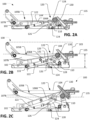
- FIG. 1 illustrates an example suspension 100 for a seat for a vehicle, such as can be securely installed in a vehicle cab via a base 102 of the suspension 100 and can support a seat portion of a seat (e.g., a seat portion 103 as shown in FIG. 2B , but potentially of a variety of other configurations) via a support portion 104.
- the suspension 100 includes movable suspension members that are configured to support the seat portion of the vehicle seat relative to the base 102 and move as the suspension is moved upward and downward relative to the base 102.
- the movable suspension members are included in a scissors-type suspension.
- the scissors-type suspension can include a set of scissor linkages 105A, 105B including crossed, pivotally connected suspension members.
- the pivotally connected suspension members of each of the scissor linkages 105A, 105B includes a first scissor link 106A, 106B pivotally coupled to a second scissor link 107A, 107B such that the first and second scissor links 106A/B, 107A/B pivot relative to each other during upward and downward movement of the suspension 100.
- the suspension 100 can also include clock or torsion springs 108 to bias the suspension 100 upwards toward a raised position. In other examples, however, a variety of other configurations are possible including other scissors-type suspensions, suspensions with other types of linkages to raise or lower a seat, suspensions with different types or arrangement of springs, and so on.
- the suspension 100 also includes a damper system 120.
- the damper system 120 includes a damper 122 and a linkage 124.
- the linkage 124 can be coupled between a base 102 of the suspension 100 and at least one of the suspension members.
- the damper 122 can be coupled between the base 102 and the linkage 124.
- the linkage 124 is connected to the damper 122, the base 102, and to the suspension members, in this case, in the form of the scissor linkages 105A, 105B.
- the linkage 124 is connected to a front, upper portion of each of the first scissor links 106A, 106B via a cross bar 110 spanning between the first scissor links 106A, 106B, although other configurations are possible.
- the damper 122 is configured to operate in different damping modes and thereby provide different damping force profiles (e.g., different damping rates or forces for a comparable input movement or force) depending on which direction the damper 122 is being moved (e.g., depending on whether the damper is being extended or compressed).
- the damper 122 is configured to provide a first damping force profile when actuated by the linkage 124 in a compression direction and a second damping force profile when actuated in an opposing extension direction.
- the first damping force profile can be configured to provide a greater damping force relative to the second damping profile.
- the first damping profile can provide a greater damping force for a given input movement or force relative to the second damping profile for the same given input movement or force.
- damper 122 any variety of known dampers can be used in other examples.
- a damper can be a one-way damper: i.e., a damper that primarily (e.g., only) provides damping when being actuated in a particular direction.
- some dampers can be configured to provide damping primarily when actuated in extension.
- other examples may exhibit other configurations.
- some dampers can primarily provide damping when actuated in compression, or can otherwise provide different amounts of damping (e.g., different damping rates or forces) depending on the direction of movement.
- a linkage can be configured to connect a damper to one or more suspension members so that the damper is only extended (or retracted) when a suspension is moved away from a reference (e.g., neutral) position and is only compressed (or extended) when the suspension is moved toward the reference (e.g., neutral) position, or vice versa.
- a damper when a damper is configured to primarily (e.g., only) provide damping when extended (or compressed), examples of the invention can result in movement of a suspension being primarily (e.g., only) dampened by the damper when the suspension is moving toward (or away) from a neutral position.
- the linkage 124 can include one or more damping links.
- the damping links include a base link 126, an intermediate link 128, and a suspension link 130.
- the base link 126 can be coupled between the base 102 and the damper 122
- the suspension link 130 can be coupled between the first scissor link 106A, 106B and the intermediate link 128, and the intermediate link 128 can be coupled between the suspension link 130 and the damper 122.
- the damping links include a base link 126, an intermediate link 128, and a suspension link 130.
- the base link 126 can be coupled between the base 102 and the damper 122
- the suspension link 130 can be coupled between the first scissor link 106A, 106B and the intermediate link 128,
- the intermediate link 128 can be coupled between the suspension link 130 and the damper 122.
- the base link 126 is pivotally secured to the base 102 at a first end (e.g., at a bracket rigidly coupled to the base 102) and is pivotally secured to the damper 122 and to the intermediate link 128 at an opposing second end.
- the intermediate link 128 is pivotally secured to the damper 122 and the base link 126 at a first end and is pivotally secured to the suspension link 130 at an opposing second end.
- the suspension link 130 is pivotally secured to the intermediate link 128 at a first end and is rigidly secured to the suspension members 160A, 106B, via the cross bar 110, at an opposing second end.
- a suspension link can be integrally formed into one of the moveable suspension members (e.g., first or second scissor links 106, 107).
- a suspension link can be configured as a bracket rigidly coupled to one of the moveable suspension members.
- the base link 126 and the intermediate link 128 are both coupled to an end of the damper 122 by a common pin 129 (e.g., a fastener). According to other examples, separate pins or other known connections can be used.
- the damper 122 is arranged such that the linkage 124 is coupled to the damper 122 at a rod end 131 of the damper 122 and the damper 122 is coupled to the base 102 at an opposite end 133.
- the damper 122 can be arranged in an opposite orientation, such that the linkage 124 is coupled to the opposite end 133 of the damper 122 and the base 102 is coupled to the rod end 131 of the damper 122.
- the linkage 124 is configured so that the damper 122 is at a reference extension.
- the neutral position can be defined as the static position of the suspension 100 under a particular load (e.g., of an operator to which the suspension 100 has been tuned), such that the suspension 100 oscillates upwards and downwards relative to the neutral position during dynamic events (e.g., bounce from road undulations).
- the neutral position can correspond to a height of a top of a seat-support platform of the suspension 100 when the suspension 100 is under a reference downward load (e.g., when loaded with the weight of an operator).
- the neutral position of the suspension 100 can correspond to a mid-ride of the suspension (i.e., halfway between a fully raised and fully lowered position of the suspension).
- the neutral position of the suspension 100 can correspond to the position of the suspension 100 reached when the suspension springs (e.g., springs 108) are appropriately adjusted to bring a seated operator statically to a middle of the suspension stroke (i.e., to a tuned mid-ride position).
- the neutral position can correspond to a reference line 135 at a vertical height A between the base 102 and the support portion 104.
- the suspension 100 can move upward and downward relative to the neutral position.
- the neutral position of the suspension 100 is approximately a middle position.
- a reference extension of the damper 122 as corresponds to the neutral position of the suspension 100, corresponds to a minimum operational extension position for the damper 122 (e.g., which may or may not correspond to an absolute minimum-extension / maximum-compression position).
- the minimum operational extension (and reference) position for the illustrated example can be defined as the end-to-end length B of the damper 122 when the suspension 100 is in the neutral position.
- the minimum operational extension position corresponds to a fully compressed damper. According to other examples, the minimum operational extension position corresponds to the most compressed position (e.g., the least extended position) of the damper 122 relative to the position of the damper 122 throughout all other suspension positions within the operational range of travel of the suspension 100.
- the linkage 124 moves to actuate the damper 122 to extend the damper 122 in a first direction.
- the actuation of the damper 122 is caused by the vertical lowering of the suspension member (e.g., the first scissor link 106), which in turn vertically lowers the suspension link 130 by virtue of the coupling therebetween.
- the lowering of the suspension link 130 rotates the intermediate link 128 in a first rotational direction (e.g., a clockwise direction from the perspective of FIG. 2A ).
- the rotation of the intermediate link 128 rotates the base link 126 in the first rotational direction to extend the damper 122 in the first direction.
- the damper 122 will dampen the downward movement of the suspension 100 (e.g., by providing the first damping force profile when actuated in the first direction), thereby assisting the upward force provided by the springs 108 (or other factors) and, in some cases, helping to ensure that the suspension 100 does not bottom out.
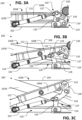
- the linkage 124 moves to actuate the damper 122 to compress the damper 122 in an opposing second direction.
- the actuation of the damper 122 is caused by the vertical raising of the suspension member (e.g., the first scissor link 106), which in turn vertically raises the suspension link 130 by virtue of the coupling therebetween.
- the raising of the suspension link 130 rotates the intermediate link 128 in an opposing second rotational direction (e.g., a counter-clockwise direction from the perspective of FIG. 2A ).
- the rotation of the intermediate link 128 rotates the base link 126 in the second rotational direction to compress the damper 122 in the second direction.
- the damper 122 will dampen the movement differently than when being extended (e.g., will not dampen or will otherwise provide less damping) during the upward movement of the suspension 100 back toward the neutral position (e.g., by providing the second damping force profile when actuated in the second direction) and the springs may be able to relatively quickly return the suspension, and thereby the seat coupled thereto, to the neutral position of FIGS. 2B and 3B .
- the linkage 124 also moves to actuate the damper 122 to extend the damper 122 in the first direction.
- the actuation of the damper 122 is caused by the vertical raising of the suspension member (e.g., the first scissor link 106), which in turn vertically raises the suspension link 130 by virtue of the coupling therebetween.
- the raising of the suspension link 130 rotates the intermediate link 128 in the second rotational direction (e.g., a counter-clockwise direction from the perspective of FIG. 2A ).
- the rotation of the intermediate link 128 rotates the base link 126 in the first rotational direction (e.g., a clockwise direction) to extend the damper 122 in the first direction.
- the damper 122 will dampen the upward movement of the suspension 100 (e.g., by providing the first damping force profile when actuated in the first direction), thereby mitigating the upward force provided by the springs 108 (or other factors) and, in some cases, helping to ensure that the suspension 100 does not top out or otherwise provide an excessive upward bounce to an operator.
- the linkage 124 moves to actuate the damper 122 to compress the damper 122 in the second direction.
- the actuation of the damper 122 is caused by the vertical lowering of the suspension member (e.g., the first scissor link 106), which in turn vertically lowers the suspension link 130 by virtue of the coupling therebetween.
- the lowering of the suspension link 130 rotates the intermediate link 128 in the first rotational direction (e.g., a clockwise direction from the perspective of FIG. 2A ).
- the rotation of the intermediate link 128 rotates the base link 126 in the second rotational direction (e.g., a counter-clockwise direction) to compress the damper 122 in the second direction.
- the damper 122 will dampen the movement differently than when being extended (e.g., will not dampen or will otherwise provide less damping) during the upward movement of the suspension 100 (e.g., by providing the second damping force profile when actuated in the second direction) and the springs may provide relatively more significant (e.g., the primary) resistance to a return to the neutral position of FIGS. 2B and 3B .
- the linkage 124 moves to actuate the damper 122 in the first direction
- the linkage 124 moves to actuate the damper in the second direction.
- the damper 122 will transition, via movement of the linkage 124, between different damping force profiles (e.g., from not damping to damping).
- the damper 122 may tend to reduce the duration and magnitude of oscillation about a neutral position for any given suspension event.
- the linkage 124 acts to transition the damper 122 from moving in one direction to moving in an opposite direction.
- the damper 122 will not be actuated (e.g., compressed) beyond the minimum operational extension position.
- the base link 126 can define an arcuate path of motion 137, which helps to define the overall movement of the damper 122. That is, in the illustrated example, although the intermediate link 128 acts to move the base link 126, and thereby the damper 122, it is the base link 126 that proscribes the path of the motion of the damper 122.
- FIGS. 4A-4C illustrate the suspension 100 with a different configuration of the linkage 124 that includes a base link 226 that is rigidly coupled to the base 102.
- the linkage 124 illustrated in FIGS. 4A-4C generally operates in the same way as the linkage 124 described with respect to FIGS. 1-3C , with the exception that the base link 226 is configured to be rigidly attached to (e.g., integrally formed with) the base 102 of the suspension 100, despite performing a similar guiding function as the base link 126 in the linkage 124 of FIGS. 2A-3C .
- a first end of the base link 226 is rigidly secured to the base 102 of the suspension 100 and an opposing second end of the base link 226 includes an arcuate slot 237 that can slidably receive a pin 229 to secure the damper 122 and the intermediate link 128.
- the arcuate slot 237 can define the same arcuate path of motion as the base link 126 of FIGS. 3A-3C .
- the intermediate link 128 acts to move the damper 122
- the base link 226 guides the motion of the damper 122 along the arcuate slot 237 such that when the suspension 100 is lowered ( FIG. 4A ) or raised ( FIG. 4C ) relative to the neutral position ( FIG. 4B ), the pin 229 slides along the slot and the damper 122 is extended or compressed.
- the arcuate slot 237 can be a circular slot, extending along a circular path between opposing ends thereof.
- the slot 237 can be sized so that the pin 229 does not contact opposing ends of the slot 237 at the opposing limits of travel of the suspension 100 or so that the slot 237 does not itself otherwise provide a travel stop for the suspension 100 at the opposing limits of travel.
- FIG. 5 illustrates another configuration of the linkage 124 that includes a base link 326 that is pivotally coupled to the base 102.
- the linkage 124 illustrated in FIG. 5 generally operates in the same way as the linkage 124 described with respect to FIGS. 1-3C , with the exception that the base link 326 includes anti-toggle features to prevent the linkage 124 from entering a toggle position.
- the base link 326 operates similarly to the base link 126 to guide movement of the damper 122.
- the base link 326 also includes a protrusion 350 extending outwardly from an end of the base link 326 adjacent to the base 102.
- the protrusion 350 is configured to engage a portion of the base 102 to stop rotation of the base link 326 relative to the base 102 at a predetermined position (i.e., to limit a range of rotation of the base link 326 and thereby limit a range of movement of the linkage 124 overall).
- a predetermined position of the base link 326 is illustrated in broken lines with the base link 326' having a protrusion 350'.
- the protrusion 350' of the base link 326' engages a surface 151 of the base 102 to stop further movement of the linkage 124.
- the predetermined position of the base link 326' defines a maximum operational extension position of the damper 122.
- the maximum operational extension position for the arrangement of FIG. 5 e.g., when the suspension 100 is in a maximum upward or downward position
- the maximum operational extension position corresponds to a fully extended damper. According to other examples, the maximum operational extension position corresponds to the most extended position of the damper 122 relative to the position of the damper 122 throughout all other suspension positions within the range of travel of the suspension 100.
- the disclosed damper system can provide various benefits compared to conventional systems, including through selective application of damping primarily to certain types or ranges of movement of a seat suspension.
- the particular configuration illustrated in the FIGS. may be particularly useful in some contexts, other configurations are also possible.
- some damper systems may be configured, under similar principles, so that a damper provides similar damping only when being compressed.
- some damper systems may be tuned (or may be tunable) so that a reference position does not necessarily correspond to a neutral or center position for an associated suspension.
Landscapes
- Engineering & Computer Science (AREA)
- Aviation & Aerospace Engineering (AREA)
- Transportation (AREA)
- Mechanical Engineering (AREA)
- Seats For Vehicles (AREA)
Claims (15)
- Aufhängung (100) für einen Fahrzeugsitz, um einen Sitzteil des Fahrzeugsitzes relativ zu einer neutralen Position nach oben und nach unten zu bewegen, wobei die Aufhängung umfasst:einen Dämpfer (122), der dazu ausgelegt ist, vor allem dann eine Dämpfung zu bewirken, wenn er in eine erste Richtung bewegt wird, die dem Ausziehen oder Zusammendrücken des Dämpfers entspricht; undein Gestänge (124), das an dem Dämpfer befestigt und dazu ausgelegt ist, zwischen einem Trägerelement (106) der Aufhängung und einem Basisteil (102) der Aufhängung befestigt zu werden; dadurch gekennzeichnet, dass das Gestänge (124) dazu ausgelegt ist, den Dämpfer (122) zu veranlassen, sich in die erste Richtung zu bewegen, wenn der Sitzabschnitt aus der neutralen Position nach oben bewegt wird und wenn der Sitzabschnitt aus der neutralen Position nach unten bewegt wird.
- Aufhängung gemäß Anspruch 1, wobei das Gestänge (124) ferner dazu ausgelegt ist, den Dämpfer (122) zu veranlassen, sich in eine zweite Richtung zu bewegen, die der ersten Richtung entgegengesetzt ist, wenn die Aufhängung nach oben in Richtung der neutralen Position bewegt wird und wenn die Aufhängung nach unten in Richtung der neutralen Position bewegt wird.
- Aufhängung gemäß einem der Ansprüche 1 und 2, wobei das Gestänge (124) einen Basislenker (126), einen Zwischenlenker (128) und einen Aufhängungslenker (130) enthält;wobei der Basislenker (126) dazu ausgelegt ist, an einem ersten Ende am Basisteil (102) befestigt zu werden und an einem zweiten Ende schwenkbar an dem Dämpfer (122) und dem Zwischenlenker (128) befestigt zu werden;wobei der Zwischenlenker (128) an einem ersten Ende schwenkbar an dem Dämpfer (122) und an dem Basislenker (126) und an einem zweiten Ende schwenkbar an dem Aufhängungslenker (130) befestigt ist; undwobei der Aufhängungslenker (130) an einem ersten Ende schwenkbar an dem Zwischenlenker (128) und an einem zweiten Ende an einem bewegbaren Aufhängungselement (106) der Aufhängung befestigt ist.
- Aufhängung gemäß Anspruch 3, wobei das erste Ende des Basislenkers (126) starr am Basisteil (102) befestigt ist und das zweite Ende des Basislenkers einen bogenförmigen Schlitz (237) aufweist, der gleitend einen Stift aufnimmt, um den Dämpfer (122) und den Zwischenlenker (128) zu befestigen.
- Aufhängung gemäß Anspruch 3, wobei der Basislenker (326) einen Vorsprung (350) aufweist, der sich von dem ersten Ende aus erstreckt, wobei der Vorsprung dazu ausgelegt ist, mit einem Abschnitt des Basisteils (102) in Eingriff zu kommen, um die Drehung des Basislenkers relativ zum Basisteil in einer vorbestimmten Position zu begrenzen.
- Aufhängung gemäß Anspruch 5, wobei die vorbestimmte Position eine maximale Auszugposition des Dämpfers oder eine minimale Auszugposition des Dämpfers definiert.
- Aufhängung gemäß einem der Ansprüche 3, 5 und 6, wobei der Basislenker (126; 326) dazu ausgelegt ist, in einer ersten Drehrichtung zu schwenken, um den Dämpfer (122) in der ersten Richtung zu betätigen, wenn die Aufhängung aus der neutralen Position heraus bewegt wird.
- Aufhängung gemäß Anspruch 7, wobei der Basislenker (126) dazu ausgelegt ist, in der ersten Drehrichtung zu schwenken, um den Dämpfer (122) in der ersten Richtung zu betätigen, wenn die Aufhängung aus der neutralen Position weg bewegt wird, unabhängig davon, ob die Aufhängung den Fahrzeugsitz in Aufwärtsrichtung oder Abwärtsrichtung bewegt; und
wobei der Basislenker (126) ferner dazu ausgelegt ist, in einer entgegengesetzten zweiten Drehrichtung zu schwenken, um den Dämpfer in einer zweiten Richtung zu betätigen, die der ersten Richtung entgegengesetzt ist, wenn die Aufhängung in Richtung der neutralen Position bewegt wird, unabhängig davon, ob die Aufhängung den Fahrzeugsitz in Aufwärtsrichtung oder in Abwärtsrichtung bewegt. - Aufhängung gemäß einem der vorhergehenden Ansprüche, wobei das Trägerelement der Aufhängung ein Scherenglied (106A, 106B) eines Scherengestänges ist.
- Aufhängung gemäß Anspruch 9, wobei die Aufhängung einen Satz von Scherengestängen umfasst, wobei jedes der Scherengestänge in dem Satz ein erstes Scherengestänge und ein zweites Scherengestänge enthält, die während der Bewegung der Aufhängung relativ zueinander schwenken; und
wobei das Trägerelement der Aufhängung eines des ersten oder zweiten Scherenglieds ist. - Aufhängung gemäß einem der vorhergehenden Ansprüche, wobei der Dämpfer (122) dazu ausgelegt ist, ein erstes Dämpfungsprofil bereitzustellen, wenn er in die erste Richtung bewegt wird, und ein zweites Dämpfungsprofil bereitzustellen, wenn er in eine zweite, der ersten Richtung entgegengesetzte Richtung bewegt wird, wobei sich das erste Dämpfungsprofil von dem zweiten Dämpfungsprofil unterscheidet.
- Aufhängung gemäß Anspruch 11, wobei das erste Dämpfungsprofil eine größere Dämpfungskraft im Vergleich zum zweiten Dämpfungsprofil für eine Referenzbewegung bereitstellt.
- Aufhängung gemäß einem der vorhergehenden Ansprüche, wobei, wenn sich die Aufhängung in einer neutralen Position befindet, die der neutralen Position des Fahrzeugsitzes entspricht, das Gestänge (124) dazu ausgelegt ist, den Dämpfer (122) in eine minimale Auszugposition oder eine maximale Auszugposition zu bringen.
- Aufhängung gemäß Anspruch 13, wobei das Gestänge (124) dazu ausgelegt ist, zu verhindern, dass der Dämpfer (122) über die minimale Auszugposition hinaus zusammengedrückt bzw. über die maximale Auszugposition hinaus ausgezogen wird.
- Fahrzeugsitz, umfassend:
einen Sitzteil, der mit der Aufhängung (100) gemäß einem der Ansprüche 1-14 gekoppelt ist.
Applications Claiming Priority (1)
| Application Number | Priority Date | Filing Date | Title |
|---|---|---|---|
| US202063082593P | 2020-09-24 | 2020-09-24 |
Publications (2)
| Publication Number | Publication Date |
|---|---|
| EP3974250A1 EP3974250A1 (de) | 2022-03-30 |
| EP3974250B1 true EP3974250B1 (de) | 2023-08-09 |
Family
ID=77951573
Family Applications (1)
| Application Number | Title | Priority Date | Filing Date |
|---|---|---|---|
| EP21198926.4A Active EP3974250B1 (de) | 2020-09-24 | 2021-09-24 | Dämpfersystem für aufhängung eines fahrzeugsitzes |
Country Status (3)
| Country | Link |
|---|---|
| US (1) | US11872916B2 (de) |
| EP (1) | EP3974250B1 (de) |
| CN (1) | CN114248671A (de) |
Family Cites Families (19)
| Publication number | Priority date | Publication date | Assignee | Title |
|---|---|---|---|---|
| GB1282193A (en) * | 1970-02-21 | 1972-07-19 | Universal Oil Prod Co | Improvements in and relating to vehicle seats and dampers therefor |
| FR2373413A1 (fr) * | 1976-12-08 | 1978-07-07 | Sifra | Siege suspendu pour tout vehicule |
| FR2568200A1 (fr) * | 1984-07-26 | 1986-01-31 | Sable | Dispositif amortisseur pour siege de vehicule. |
| US5651580A (en) | 1988-05-20 | 1997-07-29 | La-Z-Boy Chair Company | Linear actuation drive mechanism for power-assisted chairs and base therefor |
| US5125631A (en) | 1989-02-01 | 1992-06-30 | Sears Manufacturing Company | Seat suspension with cam support member and spring assisted height adjustment |
| GB2243998A (en) | 1990-05-16 | 1991-11-20 | Kab Seating Ltd | Seat suspension system |
| US6340152B1 (en) * | 1999-02-04 | 2002-01-22 | Freightliner Llc | Seat suspension vibration damper |
| US6186467B1 (en) | 1999-05-06 | 2001-02-13 | Michigan Seat Company | Full seat adjustable suspension |
| CN1735524A (zh) | 2002-11-15 | 2006-02-15 | 米尔斯科制造公司 | 车辆座椅悬架及其方法 |
| US7413158B1 (en) | 2004-11-08 | 2008-08-19 | Burer Peter J | Shock absorbing platform with dampening means |
| US7246836B2 (en) | 2005-07-06 | 2007-07-24 | Seats Incorporated | Seat having suspension system |
| US8118287B2 (en) * | 2008-05-19 | 2012-02-21 | Stidd Systems, Inc. | Shock-mitigating apparatus for seats and other objects |
| US8585004B1 (en) * | 2009-01-26 | 2013-11-19 | Atwood Mobile Products Llc | Air ride seat pedestal with independent height adjustment |
| DE102010045114B4 (de) * | 2010-09-13 | 2019-12-19 | Grammer Aktiengesellschaft | Verfahren zum Betreiben einer Fahrzeugdämpfungseinrichtung für einen Fahrzeugsitz / eine Fahrzeugkabine und Fahrzeugdämpfungseinrichtung für einen Fahrzeugsitz / eine Fahrzeugkabine |
| DE102016112105A1 (de) | 2016-07-01 | 2018-01-04 | Grammer Ag | Federungsvorrichtung |
| EP3488121B1 (de) | 2016-07-20 | 2022-03-02 | Elka Suspension Inc. | Positionsbezogenes dämpferunterstützungssystem |
| JP6804057B2 (ja) | 2016-12-09 | 2020-12-23 | デルタ工業株式会社 | サスペンション |
| DE102017115347B4 (de) | 2017-07-10 | 2020-07-02 | Grammer Ag | Fahrzeugsitz mit einstellbarem Dämpfer und Nutzfahrzeug |
| DE102018124512B4 (de) | 2018-10-04 | 2020-09-03 | Grammer Ag | Fahrzeugsitz |
-
2021
- 2021-09-22 US US17/481,850 patent/US11872916B2/en active Active
- 2021-09-24 CN CN202111119552.0A patent/CN114248671A/zh active Pending
- 2021-09-24 EP EP21198926.4A patent/EP3974250B1/de active Active
Also Published As
| Publication number | Publication date |
|---|---|
| US11872916B2 (en) | 2024-01-16 |
| US20220089071A1 (en) | 2022-03-24 |
| CN114248671A (zh) | 2022-03-29 |
| EP3974250A1 (de) | 2022-03-30 |
Similar Documents
| Publication | Publication Date | Title |
|---|---|---|
| EP2192001B1 (de) | Verstellbare Fahrzeugsitz-Federung | |
| US8585004B1 (en) | Air ride seat pedestal with independent height adjustment | |
| US5794911A (en) | Adjustable vehicle seat suspension | |
| US7152839B2 (en) | Vehicle seating system with improved vibration isolation | |
| US7350865B2 (en) | Chair having movable thigh levers | |
| EP0873905B1 (de) | Verstellbare Fahrzeugsitzaufhängung | |
| US6186467B1 (en) | Full seat adjustable suspension | |
| EP1527946A2 (de) | Fahrzeugsitzuntergestell | |
| EP0149007A1 (de) | Aufbau einer federnden Aufhängung für einen Fahrzeugsitz | |
| WO1994021154A1 (en) | Adjustable mechanized seat suspension | |
| US2606592A (en) | Vehicle seat construction | |
| CN110636780B (zh) | 椅子 | |
| EP0345439B1 (de) | Fahrzeugsitz | |
| US5273260A (en) | Seat suspension device for automotive seat | |
| EP3974250B1 (de) | Dämpfersystem für aufhängung eines fahrzeugsitzes | |
| US4890810A (en) | Seat suspension device | |
| AU1479383A (en) | Suspended seat assembly | |
| KR100993003B1 (ko) | 높이 제한 조절 기능을 갖춘 시트 현가 앗세이 | |
| US4475707A (en) | Seat suspension system | |
| JP3403789B2 (ja) | シート用サスペンション装置 | |
| KR200217274Y1 (ko) | 차량시트용 공기스프링의 공기압조절장치 | |
| WO2014092670A1 (en) | Vehicle seat suspension | |
| KR101219936B1 (ko) | 비선형 스프링 특성을 갖는 후륜 독립 현가장치 | |
| KR100511391B1 (ko) | 차량용 의자의 감쇠력 조절장치 | |
| SU1043048A1 (ru) | Подвеска сидень транспортного средства |
Legal Events
| Date | Code | Title | Description |
|---|---|---|---|
| PUAI | Public reference made under article 153(3) epc to a published international application that has entered the european phase |
Free format text: ORIGINAL CODE: 0009012 |
|
| STAA | Information on the status of an ep patent application or granted ep patent |
Free format text: STATUS: THE APPLICATION HAS BEEN PUBLISHED |
|
| AK | Designated contracting states |
Kind code of ref document: A1 Designated state(s): AL AT BE BG CH CY CZ DE DK EE ES FI FR GB GR HR HU IE IS IT LI LT LU LV MC MK MT NL NO PL PT RO RS SE SI SK SM TR |
|
| STAA | Information on the status of an ep patent application or granted ep patent |
Free format text: STATUS: REQUEST FOR EXAMINATION WAS MADE |
|
| 17P | Request for examination filed |
Effective date: 20220929 |
|
| RBV | Designated contracting states (corrected) |
Designated state(s): AL AT BE BG CH CY CZ DE DK EE ES FI FR GB GR HR HU IE IS IT LI LT LU LV MC MK MT NL NO PL PT RO RS SE SI SK SM TR |
|
| GRAP | Despatch of communication of intention to grant a patent |
Free format text: ORIGINAL CODE: EPIDOSNIGR1 |
|
| STAA | Information on the status of an ep patent application or granted ep patent |
Free format text: STATUS: GRANT OF PATENT IS INTENDED |
|
| INTG | Intention to grant announced |
Effective date: 20230302 |
|
| GRAS | Grant fee paid |
Free format text: ORIGINAL CODE: EPIDOSNIGR3 |
|
| GRAA | (expected) grant |
Free format text: ORIGINAL CODE: 0009210 |
|
| STAA | Information on the status of an ep patent application or granted ep patent |
Free format text: STATUS: THE PATENT HAS BEEN GRANTED |
|
| AK | Designated contracting states |
Kind code of ref document: B1 Designated state(s): AL AT BE BG CH CY CZ DE DK EE ES FI FR GB GR HR HU IE IS IT LI LT LU LV MC MK MT NL NO PL PT RO RS SE SI SK SM TR |
|
| REG | Reference to a national code |
Ref country code: GB Ref legal event code: FG4D |
|
| REG | Reference to a national code |
Ref country code: CH Ref legal event code: EP |
|
| REG | Reference to a national code |
Ref country code: IE Ref legal event code: FG4D |
|
| REG | Reference to a national code |
Ref country code: DE Ref legal event code: R096 Ref document number: 602021004131 Country of ref document: DE |
|
| REG | Reference to a national code |
Ref country code: LT Ref legal event code: MG9D |
|
| REG | Reference to a national code |
Ref country code: NL Ref legal event code: MP Effective date: 20230809 |
|
| REG | Reference to a national code |
Ref country code: AT Ref legal event code: MK05 Ref document number: 1597146 Country of ref document: AT Kind code of ref document: T Effective date: 20230809 |
|
| PG25 | Lapsed in a contracting state [announced via postgrant information from national office to epo] |
Ref country code: GR Free format text: LAPSE BECAUSE OF FAILURE TO SUBMIT A TRANSLATION OF THE DESCRIPTION OR TO PAY THE FEE WITHIN THE PRESCRIBED TIME-LIMIT Effective date: 20231110 |
|
| PG25 | Lapsed in a contracting state [announced via postgrant information from national office to epo] |
Ref country code: IS Free format text: LAPSE BECAUSE OF FAILURE TO SUBMIT A TRANSLATION OF THE DESCRIPTION OR TO PAY THE FEE WITHIN THE PRESCRIBED TIME-LIMIT Effective date: 20231209 |
|
| PG25 | Lapsed in a contracting state [announced via postgrant information from national office to epo] |
Ref country code: SE Free format text: LAPSE BECAUSE OF FAILURE TO SUBMIT A TRANSLATION OF THE DESCRIPTION OR TO PAY THE FEE WITHIN THE PRESCRIBED TIME-LIMIT Effective date: 20230809 Ref country code: RS Free format text: LAPSE BECAUSE OF FAILURE TO SUBMIT A TRANSLATION OF THE DESCRIPTION OR TO PAY THE FEE WITHIN THE PRESCRIBED TIME-LIMIT Effective date: 20230809 Ref country code: PT Free format text: LAPSE BECAUSE OF FAILURE TO SUBMIT A TRANSLATION OF THE DESCRIPTION OR TO PAY THE FEE WITHIN THE PRESCRIBED TIME-LIMIT Effective date: 20231211 Ref country code: NO Free format text: LAPSE BECAUSE OF FAILURE TO SUBMIT A TRANSLATION OF THE DESCRIPTION OR TO PAY THE FEE WITHIN THE PRESCRIBED TIME-LIMIT Effective date: 20231109 Ref country code: NL Free format text: LAPSE BECAUSE OF FAILURE TO SUBMIT A TRANSLATION OF THE DESCRIPTION OR TO PAY THE FEE WITHIN THE PRESCRIBED TIME-LIMIT Effective date: 20230809 Ref country code: LV Free format text: LAPSE BECAUSE OF FAILURE TO SUBMIT A TRANSLATION OF THE DESCRIPTION OR TO PAY THE FEE WITHIN THE PRESCRIBED TIME-LIMIT Effective date: 20230809 Ref country code: LT Free format text: LAPSE BECAUSE OF FAILURE TO SUBMIT A TRANSLATION OF THE DESCRIPTION OR TO PAY THE FEE WITHIN THE PRESCRIBED TIME-LIMIT Effective date: 20230809 Ref country code: IS Free format text: LAPSE BECAUSE OF FAILURE TO SUBMIT A TRANSLATION OF THE DESCRIPTION OR TO PAY THE FEE WITHIN THE PRESCRIBED TIME-LIMIT Effective date: 20231209 Ref country code: HR Free format text: LAPSE BECAUSE OF FAILURE TO SUBMIT A TRANSLATION OF THE DESCRIPTION OR TO PAY THE FEE WITHIN THE PRESCRIBED TIME-LIMIT Effective date: 20230809 Ref country code: GR Free format text: LAPSE BECAUSE OF FAILURE TO SUBMIT A TRANSLATION OF THE DESCRIPTION OR TO PAY THE FEE WITHIN THE PRESCRIBED TIME-LIMIT Effective date: 20231110 Ref country code: FI Free format text: LAPSE BECAUSE OF FAILURE TO SUBMIT A TRANSLATION OF THE DESCRIPTION OR TO PAY THE FEE WITHIN THE PRESCRIBED TIME-LIMIT Effective date: 20230809 Ref country code: AT Free format text: LAPSE BECAUSE OF FAILURE TO SUBMIT A TRANSLATION OF THE DESCRIPTION OR TO PAY THE FEE WITHIN THE PRESCRIBED TIME-LIMIT Effective date: 20230809 |
|
| PG25 | Lapsed in a contracting state [announced via postgrant information from national office to epo] |
Ref country code: PL Free format text: LAPSE BECAUSE OF FAILURE TO SUBMIT A TRANSLATION OF THE DESCRIPTION OR TO PAY THE FEE WITHIN THE PRESCRIBED TIME-LIMIT Effective date: 20230809 |
|
| PG25 | Lapsed in a contracting state [announced via postgrant information from national office to epo] |
Ref country code: ES Free format text: LAPSE BECAUSE OF FAILURE TO SUBMIT A TRANSLATION OF THE DESCRIPTION OR TO PAY THE FEE WITHIN THE PRESCRIBED TIME-LIMIT Effective date: 20230809 |
|
| PG25 | Lapsed in a contracting state [announced via postgrant information from national office to epo] |
Ref country code: SM Free format text: LAPSE BECAUSE OF FAILURE TO SUBMIT A TRANSLATION OF THE DESCRIPTION OR TO PAY THE FEE WITHIN THE PRESCRIBED TIME-LIMIT Effective date: 20230809 Ref country code: RO Free format text: LAPSE BECAUSE OF FAILURE TO SUBMIT A TRANSLATION OF THE DESCRIPTION OR TO PAY THE FEE WITHIN THE PRESCRIBED TIME-LIMIT Effective date: 20230809 Ref country code: ES Free format text: LAPSE BECAUSE OF FAILURE TO SUBMIT A TRANSLATION OF THE DESCRIPTION OR TO PAY THE FEE WITHIN THE PRESCRIBED TIME-LIMIT Effective date: 20230809 Ref country code: EE Free format text: LAPSE BECAUSE OF FAILURE TO SUBMIT A TRANSLATION OF THE DESCRIPTION OR TO PAY THE FEE WITHIN THE PRESCRIBED TIME-LIMIT Effective date: 20230809 Ref country code: DK Free format text: LAPSE BECAUSE OF FAILURE TO SUBMIT A TRANSLATION OF THE DESCRIPTION OR TO PAY THE FEE WITHIN THE PRESCRIBED TIME-LIMIT Effective date: 20230809 Ref country code: CZ Free format text: LAPSE BECAUSE OF FAILURE TO SUBMIT A TRANSLATION OF THE DESCRIPTION OR TO PAY THE FEE WITHIN THE PRESCRIBED TIME-LIMIT Effective date: 20230809 Ref country code: SK Free format text: LAPSE BECAUSE OF FAILURE TO SUBMIT A TRANSLATION OF THE DESCRIPTION OR TO PAY THE FEE WITHIN THE PRESCRIBED TIME-LIMIT Effective date: 20230809 |
|
| REG | Reference to a national code |
Ref country code: DE Ref legal event code: R097 Ref document number: 602021004131 Country of ref document: DE |
|
| PG25 | Lapsed in a contracting state [announced via postgrant information from national office to epo] |
Ref country code: LU Free format text: LAPSE BECAUSE OF NON-PAYMENT OF DUE FEES Effective date: 20230924 |
|
| REG | Reference to a national code |
Ref country code: BE Ref legal event code: MM Effective date: 20230930 |
|
| PG25 | Lapsed in a contracting state [announced via postgrant information from national office to epo] |
Ref country code: LU Free format text: LAPSE BECAUSE OF NON-PAYMENT OF DUE FEES Effective date: 20230924 Ref country code: MC Free format text: LAPSE BECAUSE OF FAILURE TO SUBMIT A TRANSLATION OF THE DESCRIPTION OR TO PAY THE FEE WITHIN THE PRESCRIBED TIME-LIMIT Effective date: 20230809 |
|
| PLBE | No opposition filed within time limit |
Free format text: ORIGINAL CODE: 0009261 |
|
| STAA | Information on the status of an ep patent application or granted ep patent |
Free format text: STATUS: NO OPPOSITION FILED WITHIN TIME LIMIT |
|
| REG | Reference to a national code |
Ref country code: IE Ref legal event code: MM4A |
|
| PG25 | Lapsed in a contracting state [announced via postgrant information from national office to epo] |
Ref country code: IE Free format text: LAPSE BECAUSE OF NON-PAYMENT OF DUE FEES Effective date: 20230924 |
|
| 26N | No opposition filed |
Effective date: 20240513 |
|
| PG25 | Lapsed in a contracting state [announced via postgrant information from national office to epo] |
Ref country code: IE Free format text: LAPSE BECAUSE OF NON-PAYMENT OF DUE FEES Effective date: 20230924 Ref country code: SI Free format text: LAPSE BECAUSE OF FAILURE TO SUBMIT A TRANSLATION OF THE DESCRIPTION OR TO PAY THE FEE WITHIN THE PRESCRIBED TIME-LIMIT Effective date: 20230809 |
|
| PG25 | Lapsed in a contracting state [announced via postgrant information from national office to epo] |
Ref country code: BE Free format text: LAPSE BECAUSE OF NON-PAYMENT OF DUE FEES Effective date: 20230930 |
|
| PG25 | Lapsed in a contracting state [announced via postgrant information from national office to epo] |
Ref country code: BG Free format text: LAPSE BECAUSE OF FAILURE TO SUBMIT A TRANSLATION OF THE DESCRIPTION OR TO PAY THE FEE WITHIN THE PRESCRIBED TIME-LIMIT Effective date: 20230809 |
|
| PG25 | Lapsed in a contracting state [announced via postgrant information from national office to epo] |
Ref country code: BG Free format text: LAPSE BECAUSE OF FAILURE TO SUBMIT A TRANSLATION OF THE DESCRIPTION OR TO PAY THE FEE WITHIN THE PRESCRIBED TIME-LIMIT Effective date: 20230809 |
|
| P01 | Opt-out of the competence of the unified patent court (upc) registered |
Free format text: CASE NUMBER: APP_491/2025 Effective date: 20250107 |
|
| REG | Reference to a national code |
Ref country code: CH Ref legal event code: PL |
|
| PG25 | Lapsed in a contracting state [announced via postgrant information from national office to epo] |
Ref country code: CH Free format text: LAPSE BECAUSE OF NON-PAYMENT OF DUE FEES Effective date: 20240930 |
|
| PG25 | Lapsed in a contracting state [announced via postgrant information from national office to epo] |
Ref country code: CY Free format text: LAPSE BECAUSE OF FAILURE TO SUBMIT A TRANSLATION OF THE DESCRIPTION OR TO PAY THE FEE WITHIN THE PRESCRIBED TIME-LIMIT; INVALID AB INITIO Effective date: 20210924 |
|
| PG25 | Lapsed in a contracting state [announced via postgrant information from national office to epo] |
Ref country code: HU Free format text: LAPSE BECAUSE OF FAILURE TO SUBMIT A TRANSLATION OF THE DESCRIPTION OR TO PAY THE FEE WITHIN THE PRESCRIBED TIME-LIMIT; INVALID AB INITIO Effective date: 20210924 |
|
| PG25 | Lapsed in a contracting state [announced via postgrant information from national office to epo] |
Ref country code: TR Free format text: LAPSE BECAUSE OF FAILURE TO SUBMIT A TRANSLATION OF THE DESCRIPTION OR TO PAY THE FEE WITHIN THE PRESCRIBED TIME-LIMIT Effective date: 20230809 |
|
| PGFP | Annual fee paid to national office [announced via postgrant information from national office to epo] |
Ref country code: DE Payment date: 20251029 Year of fee payment: 5 |
|
| PGFP | Annual fee paid to national office [announced via postgrant information from national office to epo] |
Ref country code: GB Payment date: 20251027 Year of fee payment: 5 |
|
| PGFP | Annual fee paid to national office [announced via postgrant information from national office to epo] |
Ref country code: IT Payment date: 20251021 Year of fee payment: 5 |
|
| PGFP | Annual fee paid to national office [announced via postgrant information from national office to epo] |
Ref country code: FR Payment date: 20251027 Year of fee payment: 5 |