EP3974099B1 - Kontaktvorrichtung für das laserschweissen von sekundärbatterielaschen und schweissverfahren - Google Patents
Kontaktvorrichtung für das laserschweissen von sekundärbatterielaschen und schweissverfahren Download PDFInfo
- Publication number
- EP3974099B1 EP3974099B1 EP20878098.1A EP20878098A EP3974099B1 EP 3974099 B1 EP3974099 B1 EP 3974099B1 EP 20878098 A EP20878098 A EP 20878098A EP 3974099 B1 EP3974099 B1 EP 3974099B1
- Authority
- EP
- European Patent Office
- Prior art keywords
- tight
- contact jig
- contact
- jig
- ring
- Prior art date
- Legal status (The legal status is an assumption and is not a legal conclusion. Google has not performed a legal analysis and makes no representation as to the accuracy of the status listed.)
- Active
Links
Images




Classifications
-
- B—PERFORMING OPERATIONS; TRANSPORTING
- B23—MACHINE TOOLS; METAL-WORKING NOT OTHERWISE PROVIDED FOR
- B23K—SOLDERING OR UNSOLDERING; WELDING; CLADDING OR PLATING BY SOLDERING OR WELDING; CUTTING BY APPLYING HEAT LOCALLY, e.g. FLAME CUTTING; WORKING BY LASER BEAM
- B23K26/00—Working by laser beam, e.g. welding, cutting or boring
- B23K26/20—Bonding
- B23K26/21—Bonding by welding
-
- H—ELECTRICITY
- H01—ELECTRIC ELEMENTS
- H01M—PROCESSES OR MEANS, e.g. BATTERIES, FOR THE DIRECT CONVERSION OF CHEMICAL ENERGY INTO ELECTRICAL ENERGY
- H01M50/00—Constructional details or processes of manufacture of the non-active parts of electrochemical cells other than fuel cells, e.g. hybrid cells
- H01M50/50—Current conducting connections for cells or batteries
- H01M50/531—Electrode connections inside a battery casing
-
- B—PERFORMING OPERATIONS; TRANSPORTING
- B23—MACHINE TOOLS; METAL-WORKING NOT OTHERWISE PROVIDED FOR
- B23K—SOLDERING OR UNSOLDERING; WELDING; CLADDING OR PLATING BY SOLDERING OR WELDING; CUTTING BY APPLYING HEAT LOCALLY, e.g. FLAME CUTTING; WORKING BY LASER BEAM
- B23K26/00—Working by laser beam, e.g. welding, cutting or boring
- B23K26/14—Working by laser beam, e.g. welding, cutting or boring using a fluid stream, e.g. a jet of gas, in conjunction with the laser beam; Nozzles therefor
-
- B—PERFORMING OPERATIONS; TRANSPORTING
- B23—MACHINE TOOLS; METAL-WORKING NOT OTHERWISE PROVIDED FOR
- B23K—SOLDERING OR UNSOLDERING; WELDING; CLADDING OR PLATING BY SOLDERING OR WELDING; CUTTING BY APPLYING HEAT LOCALLY, e.g. FLAME CUTTING; WORKING BY LASER BEAM
- B23K26/00—Working by laser beam, e.g. welding, cutting or boring
- B23K26/14—Working by laser beam, e.g. welding, cutting or boring using a fluid stream, e.g. a jet of gas, in conjunction with the laser beam; Nozzles therefor
- B23K26/1462—Nozzles; Features related to nozzles
- B23K26/1464—Supply to, or discharge from, nozzles of media, e.g. gas, powder, wire
- B23K26/1476—Features inside the nozzle for feeding the fluid stream through the nozzle
-
- B—PERFORMING OPERATIONS; TRANSPORTING
- B23—MACHINE TOOLS; METAL-WORKING NOT OTHERWISE PROVIDED FOR
- B23K—SOLDERING OR UNSOLDERING; WELDING; CLADDING OR PLATING BY SOLDERING OR WELDING; CUTTING BY APPLYING HEAT LOCALLY, e.g. FLAME CUTTING; WORKING BY LASER BEAM
- B23K26/00—Working by laser beam, e.g. welding, cutting or boring
- B23K26/20—Bonding
- B23K26/21—Bonding by welding
- B23K26/22—Spot welding
-
- B—PERFORMING OPERATIONS; TRANSPORTING
- B23—MACHINE TOOLS; METAL-WORKING NOT OTHERWISE PROVIDED FOR
- B23K—SOLDERING OR UNSOLDERING; WELDING; CLADDING OR PLATING BY SOLDERING OR WELDING; CUTTING BY APPLYING HEAT LOCALLY, e.g. FLAME CUTTING; WORKING BY LASER BEAM
- B23K26/00—Working by laser beam, e.g. welding, cutting or boring
- B23K26/70—Auxiliary operations or equipment
- B23K26/702—Auxiliary equipment
-
- B—PERFORMING OPERATIONS; TRANSPORTING
- B23—MACHINE TOOLS; METAL-WORKING NOT OTHERWISE PROVIDED FOR
- B23K—SOLDERING OR UNSOLDERING; WELDING; CLADDING OR PLATING BY SOLDERING OR WELDING; CUTTING BY APPLYING HEAT LOCALLY, e.g. FLAME CUTTING; WORKING BY LASER BEAM
- B23K37/00—Auxiliary devices or processes, not specially adapted for a procedure covered by only one of the other main groups of this subclass
- B23K37/04—Auxiliary devices or processes, not specially adapted for a procedure covered by only one of the other main groups of this subclass for holding or positioning work
- B23K37/0426—Fixtures for other work
- B23K37/0435—Clamps
- B23K37/0443—Jigs
-
- H—ELECTRICITY
- H01—ELECTRIC ELEMENTS
- H01M—PROCESSES OR MEANS, e.g. BATTERIES, FOR THE DIRECT CONVERSION OF CHEMICAL ENERGY INTO ELECTRICAL ENERGY
- H01M50/00—Constructional details or processes of manufacture of the non-active parts of electrochemical cells other than fuel cells, e.g. hybrid cells
- H01M50/50—Current conducting connections for cells or batteries
- H01M50/531—Electrode connections inside a battery casing
- H01M50/536—Electrode connections inside a battery casing characterised by the method of fixing the leads to the electrodes, e.g. by welding
-
- B—PERFORMING OPERATIONS; TRANSPORTING
- B23—MACHINE TOOLS; METAL-WORKING NOT OTHERWISE PROVIDED FOR
- B23K—SOLDERING OR UNSOLDERING; WELDING; CLADDING OR PLATING BY SOLDERING OR WELDING; CUTTING BY APPLYING HEAT LOCALLY, e.g. FLAME CUTTING; WORKING BY LASER BEAM
- B23K2101/00—Articles made by soldering, welding or cutting
- B23K2101/006—Vehicles
-
- B—PERFORMING OPERATIONS; TRANSPORTING
- B23—MACHINE TOOLS; METAL-WORKING NOT OTHERWISE PROVIDED FOR
- B23K—SOLDERING OR UNSOLDERING; WELDING; CLADDING OR PLATING BY SOLDERING OR WELDING; CUTTING BY APPLYING HEAT LOCALLY, e.g. FLAME CUTTING; WORKING BY LASER BEAM
- B23K2101/00—Articles made by soldering, welding or cutting
- B23K2101/36—Electric or electronic devices
-
- B—PERFORMING OPERATIONS; TRANSPORTING
- B23—MACHINE TOOLS; METAL-WORKING NOT OTHERWISE PROVIDED FOR
- B23K—SOLDERING OR UNSOLDERING; WELDING; CLADDING OR PLATING BY SOLDERING OR WELDING; CUTTING BY APPLYING HEAT LOCALLY, e.g. FLAME CUTTING; WORKING BY LASER BEAM
- B23K2101/00—Articles made by soldering, welding or cutting
- B23K2101/36—Electric or electronic devices
- B23K2101/38—Conductors
-
- Y—GENERAL TAGGING OF NEW TECHNOLOGICAL DEVELOPMENTS; GENERAL TAGGING OF CROSS-SECTIONAL TECHNOLOGIES SPANNING OVER SEVERAL SECTIONS OF THE IPC; TECHNICAL SUBJECTS COVERED BY FORMER USPC CROSS-REFERENCE ART COLLECTIONS [XRACs] AND DIGESTS
- Y02—TECHNOLOGIES OR APPLICATIONS FOR MITIGATION OR ADAPTATION AGAINST CLIMATE CHANGE
- Y02E—REDUCTION OF GREENHOUSE GAS [GHG] EMISSIONS, RELATED TO ENERGY GENERATION, TRANSMISSION OR DISTRIBUTION
- Y02E60/00—Enabling technologies; Technologies with a potential or indirect contribution to GHG emissions mitigation
- Y02E60/10—Energy storage using batteries
Definitions
- the present invention relates to a tight-contact jig for secondary battery tab laser welding and a welding method, as shown for instance in the preamble of the independent claims (see, for example, CN207043555 U ), and more particularly to a tight-contact jig for secondary battery tab laser welding including an upper tight-contact jig including a ring-shaped spray portion capable of performing surface spray in order to inhibit deterioration in weld quality due to reaction with hydrogen or oxygen in air at the time of laser welding for forming an electrode terminal and to inhibit the occurrence of short circuit due to deposition of spatter generated at the time of welding and a welding method.
- An all solid state battery which has high stability, high energy density, and a long lifespan, is technology enabling a new market for lithium secondary batteries.
- Lithium secondary batteries may be classified into a can-shaped secondary battery having an electrode assembly mounted in a metal can and a pouch-shaped secondary battery having an electrode assembly mounted in a pouch made of an aluminum laminate sheet.
- a secondary battery is generally manufactured through processes in which an electrolytic solution is injected into a sheathing member in the state in which an electrode assembly is received in the sheathing member and then the sheathing member is sealed.
- a pouch-shaped secondary battery includes an electrode assembly in which a positive electrode plate and a negative electrode plate are disposed spaced apart from each other so as to be opposite each other, an electrode lead disposed so as to extend from the electrode assembly, and a pouch sheathing member configured to receive the electrode assembly and an electrolytic solution.
- the electrode lead which is a portion that is connected to the electrode assembly and is exposed out of the pouch sheathing member, serves as an electrode terminal that is capable of being electrically connected to another secondary battery or an external device.
- the electrode lead may be connected to an electrode tab directly connected to the electrode assembly.
- at least one positive electrode tab and at least one negative electrode tab may be connected to a positive electrode lead and a negative electrode lead, respectively.
- a battery cell constituted by the pouch-shaped secondary battery has an operation voltage of about 2.5 V to 4.2 V.
- a plurality of battery cells is connected to each other in series to constitute a battery module.
- a plurality of battery cells is connected to each other in parallel to constitute a battery module. Consequently, the number of battery cells included in a certain battery module may be variously set depending on required output voltage or required charging and discharging capacities.
- electrode leads of the battery cells are welded using a laser such that the electrode leads are electrically connected to each other.
- a laser beam is radiated on portions to be welded to perform spot welding in the state in which two battery cells are disposed so as to face each other and electrode tabs, connection portions between electrode tabs and electrode leads, and electrode lead portions of the respective battery cells are brought into vertical contact with each other.
- welding must be performed in the state in which the upper electrode lead and the lower electrode lead are in completely tight contact with each other.
- Japanese Patent Application Publication No. 2002-164037 discloses technology for welding a battery electrode plate group shelf.
- Japanese Patent Application Publication No. 1994-304777 discloses laser welding technology capable of blocking air at a weld portion by spraying nitrogen as an inert gas.
- Japanese Patent Application Publication No. 2001-150169 discloses technology capable of reducing the flow rate of assistant gas that is used when non-oxidation cutting is performed using a laser processing machine for cutting.
- Japanese Patent Application Publication No. 2016-018756 discloses technology for supplying assistant gas to a laser light radiation area in an inner case in the state in which one end of an outer case is in contact with a protective plate in an electrode assembly manufacturing method.
- an upper tight-contact jig having a dual structure including a ring-shaped spray portion configured to spray nitrogen gas in order to eliminate an oxidation reaction and spatter deposition occurring at the time of welding.
- Such a dual structure is technology for spraying nitrogen to a weld portion in order to form a nitrogen atmosphere and forming an ascending air current such that fumes and spatter generated at the time of subsequent welding are not discharged to the outside but are well introduced into an inner suction portion.
- the present invention has been made in view of the above problems, and it is an object of the present invention to provide a tight-contact jig for secondary battery tab laser welding including an upper tight-contact jig including a ring-shaped spray portion capable of performing surface spraying in order to inhibit deterioration in weld quality due to reaction with hydrogen or oxygen in air at the time of laser welding for forming an electrode terminal and to inhibit the occurrence of short circuit due to deposition of spatter generated at the time of welding and a welding method.
- the present invention provides an upper tight-contact jig for welding used to manufacture an electrode terminal according to claim 1.
- the present invention provides a tight-contact jig for welding according to claim 5.
- the present invention provides a welding method for manufacturing an electrode terminal according to claim 7.
- FIG. 1 is a schematic view showing a welding system using a conventional jig.
- a pouch-shaped secondary battery includes an electrode assembly in which a positive electrode plate and a negative electrode plate are disposed spaced apart from each other so as to be opposite each other, an electrode lead disposed so as to extend from the electrode assembly, and a pouch sheathing member configured to receive the electrode assembly and an electrolytic solution.
- the electrode lead which is a portion that is connected to the electrode assembly and is exposed out of the pouch sheathing member, serves as an electrode terminal that is capable of being electrically connected to another secondary battery or an external device.
- the electrode lead may be connected to an electrode tab directly connected to the electrode assembly.
- at least one positive electrode tab and at least one negative electrode tab may be connected to a positive electrode lead and a negative electrode lead, respectively.
- a battery cell constituted by the pouch-shaped secondary battery has an operation voltage of about 2.5 V to 4.2 V.
- a plurality of battery cells is connected to each other in series to constitute a battery module.
- a plurality of battery cells is connected to each other in parallel to constitute a battery module. Consequently, the number of battery cells included in a certain battery module may be variously set depending on required output voltage or required charging and discharging capacities.
- electrode leads 2 of the battery cells are welded using a laser 1 such that the electrode leads are electrically connected to each other.
- a laser beam is radiated on portions to be welded to perform spot welding in the state in which two battery cells are disposed so as to face each other and electrode lead portions of the respective battery cells are brought into vertical contact with each other.
- welding must be performed in the state in which the upper electrode lead and the lower electrode lead are in completely tight contact with each other.
- a conventional support 3 configured to support the electrode leads is used, however, it is not possible to completely correct uneven surface states of the electrode leads, whereby it is not easy to secure tight contact between the electrode leads at the time of laser welding.
- FIG. 2 is a photograph showing an oxidation phenomenon and holes generated at a welded surface formed using the conventional jig.
- a nitrogen supply hole was formed in order to supply nitrogen, whereby the flow speed of sprayed nitrogen gas was high and the flow rate of the sprayed nitrogen gas was low. As a result, nitrogen gas having a spray pressure of 0.01 MPa or higher could not be used.
- the portion of the jig abutting a weld portion was spaced apart therefrom by about 4 mm, whereby it was not easy to inhibit oxidation reaction due to the nitrogen gas.
- the nitrogen gas was directly sprayed to the weld portion, whereby a phenomenon in which beads scattered when the weld portion was melted occurred.
- FIG. 3 is a photograph showing the section of a weld portion formed using the conventional jig.
- FIG. 4 is a photograph showing spatter formed in the conventional jig after welding using the jig.
- the spatter In the tight-contact jig for welding, the spatter is cumulatively piled up at the end of the tight-contact jig. When the spatter accumulates, a quality problem, such as short circuit, is caused afterwards. Therefore, it is necessary to periodically clean and replace the tight-contact jig.
- FIG. 5 is a plan view of an outer upper tight-contact jig according to an embodiment of the present invention.
- FIG. 6 is a plan view of an inner upper tight-contact jig according to an embodiment of the present invention.
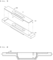
- FIG. 7 is a perspective view of an upper tight-contact jig in which the outer upper tight-contact jig and the inner upper tight-contact jig according to the embodiment of the present invention are coupled to each other.
- an upper tight-contact jig for welding configured to manufacture an electrode terminal including a ring-shaped spray portion 111 configured to spray an inert gas so as to be brought into tight contact with one surface of a weld portion of a plurality of secondary batteries.
- the kind of the inert gas is not restricted as long as the inert gas does not react with hydrogen and/or oxygen in air.
- the inert gas is nitrogen gas.
- the ring-shaped spray portion 111 is formed in a circular shape, an oval shape, a rectangular shape, a square shape, or an amorphous shape, and the inert gas is not sprayed through a ring-shaped central portion.
- opposite ends of the ring-shaped spray portion have hemispherical shapes having the same diameter, and a ring-shaped extension portion formed as the result of extension of the opposite ends has a width equal to the diameter of the hemisphere, whereby the ring-shaped spray portion has a rectangular shape.
- the ring-shaped spray portion may spray the inert gas through only a part that forms the outer surface of the ring shape.
- the ring-shaped spray portion is a surface-shaped spray portion, rather than a nozzle-shaped spray port.
- the weld portion is, according to the present invention, any one of an electrode tab, an electrode tab and an electrode lead, and an electrode lead.
- the ring-shaped central portion 112 of the ring-shaped spray portion may suction the sprayed inert gas and may discharge the suctioned inert gas to the outside.
- nitrogen gas introduced through the ring-shaped spray portion may be suctioned through the ring-shaped central portion and may be discharged to the outside.
- a reducing atmosphere may be uniformly formed over the entire weld portion.
- a discharge port configured to discharge the suctioned nitrogen gas to the outside may be formed in the laser welding unit.
- the upper tight-contact jig includes, according to the present invention, an outer upper tight-contact jig 110, which defines the outer surface of the ring-shaped spray portion, and an inner upper tight-contact jig 120, which defines the inner surface of the ring-shaped spray portion.
- a gas introduction port 113, through which the inert gas is introduced, may be formed in the side surface of the outer upper tight-contact jig.
- the sectional area of the ring-shaped spray portion gradually decreases from the upper surface to the bottom surface of the upper tight-contact jig.
- the ring-shaped spray portion may be formed as the result of coupling between the outer upper tight-contact jig and the inner upper tight-contact jig, and as the sectional area of the ring-shaped spray portion becomes smaller, a slit of the ring-shaped spray portion abutting the weld portion may be formed so as to be smaller.
- the ring-shaped spray portion may be bent once or more while being formed from the upper surface to the bottom surface of the upper tight-contact jig.
- the slit of the ring-shaped spray portion abutting the weld portion may be formed so as to be small.
- the bottom surface of the outer upper tight-contact jig abuts, in use, the weld portion and the bottom surface of the inner upper tight-contact jig is spaced apart therefrom by a predetermined height to form the ring-shaped spray portion.
- the spray pressure of the sprayed inert gas may range from 0.1 MPa to 0.5 MPa, preferably from 0.15 MPa to 0.4 MPa, more preferably from 0.2 MPa to 0.3 MPa. At this time, the flow rate of the inert gas may be 10 to 30 L/min. If the spray pressure condition is not satisfied, it is not possible to uniformly form a reducing atmosphere at the weld portion through the inert gas.
- FIG. 8 is a long-direction sectional view of the upper tight-contact jig in which the outer upper tight-contact jig and the inner upper tight-contact jig according to the embodiment of the present invention are coupled to each other.
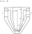
- FIG. 9 is a short-direction sectional view of the upper tight-contact jig in which the outer upper tight-contact jig and the inner upper tight-contact jig according to the embodiment of the present invention are coupled to each other.
- a tight-contact jig for welding including the upper tight-contact jig and a lower tight-contact jig formed so as to be brought into tight contact with the other surface of the weld portion in a direction opposite the upper tight-contact jig.
- the upper tight-contact jig may include an upper connection portion configured to move upwards and downwards or leftwards and rightwards in order to support one surface of the weld portion in tight contact therewith, and the lower tight-contact jig may include a lower connection portion configured to move upwards and downwards or leftwards and rightwards in order to support the other surface of the weld portion in tight contact therewith.
- the upper connection portion and/or the lower connection portion may be a first guide rod configured to guide the translation of the upper tight-contact jig and/or the lower tight-contact jig.
- the upper connection portion and/or the lower connection portion may be a second guide rod configured to guide the horizontal relative movement of the upper tight-contact jig and/or the lower tight-contact jig.
- One end of the upper connection portion may be connected to the lower tight-contact jig, and one end of the lower connection portion may be connected to the upper tight-contact jig.
- the upper tight-contact jig and the lower tight-contact jig may be formed in a vertically open shape in order to perform welding in the state of being in tight contact with each other at the surface opposite the weld portion.
- FIG. 10 is a sectional view of a laser welding unit having a tight-contact jig according to an embodiment of the present invention coupled thereto.
- a welding method for manufacturing an electrode terminal including a first step of vertically overlapping welding targets of a weld portion, which is any one of a plurality of electrode tabs, an electrode tab and an electrode lead, and an electrode lead, a second step of positioning an upper tight-contact jig and a lower tight-contact jig so as to be brought into tight contact with the weld portion, a third step of pressing the upper tight-contact jig toward the upper surface of the weld portion, the upper tight-contact jig including a ring-shaped spray portion 111 configured to spray an inert gas so as to be brought into tight contact with the upper surface of the weld portion, a fourth step of pressing the lower tight-contact jig toward the lower surface of the weld portion so as to be brought into tight contact with the lower surface of the weld portion, and a fifth step of irradiating the welding targets of the weld portion with a laser beam.
- the inert gas sprayed through the ring-shaped spray portion may be suctioned through the ring-shaped central portion of the ring-shaped spray portion.
- the upper tight-contact jig includes, according to the present invention, an outer upper tight-contact jig 110, which defines the outer surface of the ring-shaped spray portion, and an inner upper tight-contact jig 120, which defines the inner surface of the ring-shaped spray portion.
- FIG. 11 is a photograph showing an oxidation phenomenon and holes generated at a welded surface formed using the upper tight-contact jig according to the embodiment of the present invention.
- FIG. 12 is a photograph showing the section of the weld portion formed using the upper tight-contact jig according to the embodiment of the present invention.
- FIG. 13 is a photograph showing spatter formed in the upper tight-contact jig according to the embodiment of the present invention after welding using the jig.
- the present invention may provide a battery cell manufactured using the welding method for manufacturing the electrode terminal.
- the present invention may provide a battery pack including two or more battery cells.
- the present invention may provide a device using the battery cell as an energy source.
- the device may be a mobile phone, a portable computer, a smartphone, a smart pad, a netbook computer, a light electronic vehicle (LEV), an electric vehicle, a hybrid electric vehicle, a plug-in hybrid electric vehicle, or a power storage apparatus.
- LEV light electronic vehicle
- the tight-contact jig for secondary battery tab laser welding and the welding method have an effect in that it is possible to prevent reaction with hydrogen and/or oxygen in air at the weld portion at the time of welding, whereby it is possible to prevent deterioration in weld quality.
- the tight-contact jig for secondary battery tab laser welding and the welding method have an effect in that it is possible to prevent occurrence of a phenomenon in which spatter is continuously generated and cumulatively deposited in the jig.
- the tight-contact jig for secondary battery tab laser welding and the welding method have an effect in that it is possible to prevent occurrence of short circuit as the result of the deposited spatter being introduced to the lead of the battery cell.
- the tight-contact jig for secondary battery tab laser welding and the welding method have an effect in that nitrogen is sprayed through the ring-shaped spray portion, and therefore it is possible to decrease flow speed of the sprayed nitrogen and to increase flow rate of the sprayed nitrogen, whereby it is possible to realize surface-shaped spray, rather than conventional dot-shaped spray.
- the tight-contact jig for secondary battery tab laser welding and the welding method have an effect in that it is possible to minimize physical space in which spatter may be burned and to form an ascending air current such that the spatter is well transferred to the ring-shaped central portion.
Landscapes
- Engineering & Computer Science (AREA)
- Physics & Mathematics (AREA)
- Optics & Photonics (AREA)
- Mechanical Engineering (AREA)
- Plasma & Fusion (AREA)
- Chemical & Material Sciences (AREA)
- Chemical Kinetics & Catalysis (AREA)
- Electrochemistry (AREA)
- General Chemical & Material Sciences (AREA)
- Connection Of Batteries Or Terminals (AREA)
- Sealing Battery Cases Or Jackets (AREA)
Claims (8)
- Obere Dicht-Kontakt-Vorrichtung (100) zum Schweißen, welche verwendet wird, um einen Elektrodenanschluss herzustellen, wobei die obere Dicht-Kontakt-Vorrichtung (100) umfasst:einen ringförmigen Sprühabschnitt (111), welcher dazu eingerichtet ist, bei Verwendung, Inertgas zu sprühen, um in dichten Kontakt mit einer Fläche eines Schweißabschnitts einer Mehrzahl von Sekundärbatterien gebracht zu werden, undeine äußere obere Dicht-Kontakt-Vorrichtung (110), welche eine äußere Fläche des ringförmigen Sprühabschnitts (111) definiert, und eine innere obere Dicht-Kontakt-Vorrichtung (120), welche eine innere Fläche des ringförmigen Sprühabschnitts (111) definiert,wobei eine Bodenfläche der äußeren oberen Dicht-Kontakt-Vorrichtung (110) dazu eingerichtet ist, bei Verwendung, an dem Schweißabschnitt anzuliegen, und eine Bodenfläche der inneren oberen Dicht-Kontakt-Vorrichtung (120) davon um eine vorbestimmte Höhe beabstandet ist, um den ringförmigen Sprühabschnitt (111) zu bilden,und dadurch gekennzeichnet, dasseine Querschnittsfläche des ringförmigen Sprühabschnitts (111) von einer oberen Fläche zu einer Bodenfläche der oberen Dicht-Kontakt-Vorrichtung (100) graduell abnimmt.
- Obere Dicht-Kontakt-Vorrichtung (100) nach Anspruch 1, wobei ein ringförmiger zentraler Abschnitt (112) des ringförmigen Sprühabschnitts (111) dazu eingerichtet ist, bei Verwendung, das gesprühte Inertgas einzusaugen, und das eingesaugte Inertgas zu einem Äußerem absondert.
- Obere Dicht-Kontakt-Vorrichtung (100) nach Anspruch 1, wobei die äußere obere Dicht-Kontakt-Vorrichtung (110) in einer Seitenfläche davon mit einer Gaseinleitungsöffnung (113) bereitgestellt ist, welche dazu eingerichtet ist, dem Inertgas zu erlauben, dort hindurch eingeleitet zu werden.
- Obere Dicht-Kontakt-Vorrichtung (100) nach Anspruch 1, wobei der ringförmige Sprühabschnitt (111) einmal oder mehrmals gebogen ist, während er von einer oberen Fläche zu einer Bodenfläche der oberen Dicht-Kontakt-Vorrichtung (100) gebildet ist.
- Dicht-Kontakt-Vorrichtung zum Schweißen, umfassend:die obere Dicht-Kontakt-Vorrichtung (100) nach einem der Ansprüche 1 bis 4; undeine untere Dicht-Kontakt-Vorrichtung (200), welche derart gebildet ist, dass sie, bei Verwendung, in dichten Kontakt mit der anderen Fläche der Kontakt-Vorrichtung gebracht ist.
- Dicht-Kontakt-Vorrichtung nach Anspruch 9, wobeidie obere Dicht-Kontakt-Vorrichtung (100) einen oberen Verbindungsabschnitt (300) umfasst, welcher dazu eingerichtet ist, sich, bei Verwendung, nach oben und nach unten oder nach links und nach rechts zu bewegen, um die eine Fläche des Schweißabschnitts in dichtem Kontakt damit zu haltern; unddie untere Dicht-Kontakt-Vorrichtung (200) einen unteren Verbindungsabschnitt (400) umfasst, welcher dazu eingerichtet ist, sich bei Verwendung nach oben und nach unten oder nach links und nach rechts zu bewegen, um die andere Fläche des Schweißabschnitts in dichtem Kontakt damit zu haltern.
- Schweißverfahren zur Herstellung eines Elektrodenanschlusses, wobei das Schweißverfahren gekennzeichnet ist durch:einen ersten Schritt eines vertikalen Überlappens von Schweißzielen eines Schweißabschnitts, wobei der Schweißabschnitt eines aus einer Mehrzahl von Elektrodenlaschen, einer Elektrodenlasche und einer Elektrodenleitung, und einer Elektrodenleitung ist;einen zweiten Schritt eines Positionierens der oberen Dicht-Kontakt-Vorrichtung (100) nach einem der Ansprüche 1 bis 4; und einer unteren Dicht-Kontakt-Vorrichtung (200), um in dichten Kontakt mit dem Schweißabschnitt gebracht zu werden;einen dritten Schritt eines Pressens der oberen Dicht-Kontakt-Vorrichtung (100) in Richtung einer oberen Fläche des Schweißabschnitts, die obere Dicht-Kontakt-Vorrichtung (100);einen vierten Schritt eines Pressens der unteren Dicht-Kontakt-Vorrichtung (200) in Richtung einer unteren Fläche des Schweißabschnitts, um in dichten Kontakt mir der unteren Fläche des Schweißabschnitts gebracht zu werden; undeinen fünften Schritt eines Bestrahlens der Schweißziele des Schweißabschnitts mit einem Laserstrahl.
- Schweißverfahren nach Anspruch 7, wobei das Inertgas, welches durch den ringförmigen Sprühabschnitt (111) gesprüht wird, durch einen ringförmigen zentralen Abschnitt (112) des ringförmigen Sprühabschnitts (111) angesaugt wird.
Applications Claiming Priority (2)
| Application Number | Priority Date | Filing Date | Title |
|---|---|---|---|
| KR1020190131954A KR102833705B1 (ko) | 2019-10-23 | 2019-10-23 | 이차전지 탭 레이저 용접을 위한 밀착 지그 및 용접 방법 |
| PCT/KR2020/013198 WO2021080207A1 (ko) | 2019-10-23 | 2020-09-28 | 이차전지 탭 레이저 용접을 위한 밀착 지그 및 용접 방법 |
Publications (3)
| Publication Number | Publication Date |
|---|---|
| EP3974099A1 EP3974099A1 (de) | 2022-03-30 |
| EP3974099A4 EP3974099A4 (de) | 2022-07-20 |
| EP3974099B1 true EP3974099B1 (de) | 2024-08-14 |
Family
ID=75620104
Family Applications (1)
| Application Number | Title | Priority Date | Filing Date |
|---|---|---|---|
| EP20878098.1A Active EP3974099B1 (de) | 2019-10-23 | 2020-09-28 | Kontaktvorrichtung für das laserschweissen von sekundärbatterielaschen und schweissverfahren |
Country Status (7)
| Country | Link |
|---|---|
| US (1) | US20220184738A1 (de) |
| EP (1) | EP3974099B1 (de) |
| KR (1) | KR102833705B1 (de) |
| CN (1) | CN114040828B (de) |
| ES (1) | ES2987017T3 (de) |
| HU (1) | HUE068120T2 (de) |
| WO (1) | WO2021080207A1 (de) |
Families Citing this family (13)
| Publication number | Priority date | Publication date | Assignee | Title |
|---|---|---|---|---|
| KR20230054287A (ko) | 2021-10-15 | 2023-04-24 | 주식회사 엘지에너지솔루션 | 레이저 용접 장치 및 이에 사용되는 마스크 지그의 교체 방법 |
| KR102803276B1 (ko) * | 2021-10-20 | 2025-05-07 | 주식회사 엘지에너지솔루션 | 레이저용접장치 |
| CN114932313A (zh) * | 2022-05-13 | 2022-08-23 | 广东利元亨技术有限公司 | 极耳焊接装置和方法 |
| KR102730998B1 (ko) | 2022-07-08 | 2024-11-15 | 주식회사 엠플러스 | 이차전지 초음파 용접장치 |
| KR102731007B1 (ko) | 2022-07-11 | 2024-11-15 | 주식회사 엠플러스 | 이차전지 탭 초음파 용접 장치의 호온 각도 조정 장치 및 호온 각도 조정 방법 |
| KR20240028073A (ko) * | 2022-08-24 | 2024-03-05 | 주식회사 엘지에너지솔루션 | 용접용 지그의 이물질 모니터링 시스템 및 용접용 지그의 이물질을 모니터링하는 방법 |
| KR20240076283A (ko) | 2022-11-23 | 2024-05-30 | 주식회사 엘지에너지솔루션 | 레이저 용접 시스템 |
| JP7746647B2 (ja) * | 2023-03-09 | 2025-10-01 | エルジー エナジー ソリューション リミテッド | 電極タブと電極リードのレーザー溶接装置及びこれを用いた溶接方法 |
| KR20250035302A (ko) * | 2023-09-05 | 2025-03-12 | 주식회사 엘지에너지솔루션 | 용접용 지그 및 이를 포함하는 레이저 용접 장치 |
| IT202400006529A1 (it) * | 2024-03-25 | 2025-09-25 | Ima Spa | Macchina per realizzare dispositivi di accumulo di energia elettrica. |
| KR20250165822A (ko) | 2024-05-20 | 2025-11-27 | 주식회사 시스템알앤디 | 압력 측정에 기반한 레이저 용접 가공 방법 및 레이저 용접 가공 장치 |
| KR20260009640A (ko) | 2024-07-11 | 2026-01-20 | 주식회사 엠플러스 | 마스크 지그 교체 편의성을 향상시킨 레이저 웰딩 장치 및 마스크 지그 초기 셋팅 방법 |
| KR20260029826A (ko) * | 2024-08-26 | 2026-03-05 | 주식회사 엘지에너지솔루션 | 이물질 제거가 용이한 전극조립체 가공장치 및 이를 이용한 전극조립체 가공방법 |
Family Cites Families (22)
| Publication number | Priority date | Publication date | Assignee | Title |
|---|---|---|---|---|
| IL92427A0 (en) * | 1989-02-08 | 1990-07-26 | Gen Electric | Laser welding apparatus and process |
| JPH06304777A (ja) | 1993-04-27 | 1994-11-01 | Sanyo Electric Co Ltd | 電池の封口板を外装缶にレーザー溶接するガスノズル |
| JP3286626B2 (ja) | 1999-11-30 | 2002-05-27 | 日本酸素株式会社 | 切断用レーザ加工機及びそれを使用した切断方法 |
| JP3812300B2 (ja) * | 2000-07-14 | 2006-08-23 | 富士通株式会社 | レーザスポット溶接装置 |
| JP2002164037A (ja) | 2000-11-27 | 2002-06-07 | Matsushita Electric Ind Co Ltd | 鉛蓄電池用極板群棚の製造方法 |
| JP4205486B2 (ja) * | 2003-05-16 | 2009-01-07 | 株式会社ディスコ | レーザ加工装置 |
| JP4408080B2 (ja) * | 2004-02-10 | 2010-02-03 | パナソニック株式会社 | ハイブリッドレーザ加工方法とそれに用いるハイブリッドレーザトーチ |
| US7259353B2 (en) * | 2004-09-30 | 2007-08-21 | Honeywell International, Inc. | Compact coaxial nozzle for laser cladding |
| JP2010105041A (ja) * | 2008-09-30 | 2010-05-13 | Sanyo Electric Co Ltd | レーザ溶接用治具、レーザ溶接装置及び角形電池の製造方法 |
| CN201329320Y (zh) * | 2008-12-25 | 2009-10-21 | 沈阳大陆激光柔性制造技术有限公司 | 带水冷及导向气体保护的同轴送粉喷嘴 |
| JP5654780B2 (ja) * | 2010-06-17 | 2015-01-14 | 株式会社レーザックス | レーザ切断・レーザ溶接両用ノズル、それを用いたレーザ加工機、およびレーザ切断・レーザ溶接両用ノズルを用いた板突き合わせ溶接方法 |
| JP2014136254A (ja) * | 2013-01-18 | 2014-07-28 | Mitsubishi Heavy Ind Ltd | レーザ溶接用治具およびこれを用いたレーザ溶接方法 |
| JP6099432B2 (ja) * | 2013-02-28 | 2017-03-22 | エイチアールディー株式会社 | リモートレーザ加工装置 |
| EP3109925B1 (de) * | 2014-03-31 | 2022-05-11 | LG Energy Solution, Ltd. | Batteriemodul und batteriepack damit |
| JP6295861B2 (ja) | 2014-07-11 | 2018-03-20 | 株式会社豊田自動織機 | 電極体製造方法 |
| US10195688B2 (en) * | 2015-01-05 | 2019-02-05 | Johnson Controls Technology Company | Laser welding system for a battery module |
| KR102165327B1 (ko) * | 2017-04-04 | 2020-10-13 | 주식회사 엘지화학 | 전극 리드 밀착용 지그 및 전극 리드 용접 방법 |
| CN207043555U (zh) * | 2017-06-29 | 2018-02-27 | 大族激光科技产业集团股份有限公司 | 一种翻转片焊接吹气装置 |
| DE102017214025B4 (de) * | 2017-08-11 | 2021-10-07 | Thyssenkrupp Ag | Spannwerkzeug zum Zusammenspannen von mittels Laserschweißen zu verschweißenden Blechen und dazugehöriges Verfahren |
| KR102444124B1 (ko) * | 2017-10-16 | 2022-09-16 | 주식회사 엘지에너지솔루션 | 배터리 모듈 및 이를 포함하는 배터리 팩 |
| US10944096B2 (en) * | 2018-04-10 | 2021-03-09 | GM Global Technology Operations LLC | Method of manufacturing a lithium metal negative electrode |
| KR102079005B1 (ko) | 2018-05-18 | 2020-02-19 | 한국에너지기술연구원 | 일가이온 선택성 패턴을 갖는 이온 교환막 및 이를 포함하는 역전기투석장치 |
-
2019
- 2019-10-23 KR KR1020190131954A patent/KR102833705B1/ko active Active
-
2020
- 2020-09-28 ES ES20878098T patent/ES2987017T3/es active Active
- 2020-09-28 EP EP20878098.1A patent/EP3974099B1/de active Active
- 2020-09-28 CN CN202080046802.XA patent/CN114040828B/zh active Active
- 2020-09-28 US US17/631,177 patent/US20220184738A1/en active Pending
- 2020-09-28 WO PCT/KR2020/013198 patent/WO2021080207A1/ko not_active Ceased
- 2020-09-28 HU HUE20878098A patent/HUE068120T2/hu unknown
Also Published As
| Publication number | Publication date |
|---|---|
| KR20210048096A (ko) | 2021-05-03 |
| HUE068120T2 (hu) | 2024-12-28 |
| US20220184738A1 (en) | 2022-06-16 |
| EP3974099A1 (de) | 2022-03-30 |
| ES2987017T3 (es) | 2024-11-13 |
| CN114040828B (zh) | 2024-03-29 |
| EP3974099A4 (de) | 2022-07-20 |
| WO2021080207A1 (ko) | 2021-04-29 |
| CN114040828A (zh) | 2022-02-11 |
| KR102833705B1 (ko) | 2025-07-14 |
Similar Documents
| Publication | Publication Date | Title |
|---|---|---|
| EP3974099A1 (de) | Kontaktvorrichtung für das laserschweissen von sekundärbatterielaschen und schweissverfahren | |
| KR101161965B1 (ko) | 이차전지용 집전단자판, 이차전지 및 이차전지의 제조방법 | |
| KR102808445B1 (ko) | 전극 탭 용접 장치 및 방법 | |
| KR102570969B1 (ko) | 원통형 리튬 이온 이차 전지 | |
| CN218769655U (zh) | 圆柱形二次电池、电池组以及车辆 | |
| US10056597B2 (en) | Connecting structure and method between grid and electrode tab of secondary battery | |
| US10062897B2 (en) | Battery electrode and a method for producing same | |
| US20130252086A1 (en) | Battery electrode and method for producing same | |
| US9300013B2 (en) | Battery module | |
| KR101804614B1 (ko) | 음극에 리드를 용접하는 방법, 이에 의해 제조된 배터리용 음극 및 이를 포함하는 이차전지 | |
| EP4383442B1 (de) | Schweissvorrichtung | |
| US20240283104A1 (en) | Electrode Tab and Method for Cutting Electrode Tab | |
| EP2071646A1 (de) | Batteriekernhülle und batterie | |
| KR102070590B1 (ko) | 용접 부위에 금속층을 포함하는 전지셀의 제조방법 | |
| JP2006310313A (ja) | 二次電池及び二次電池の製造方法 | |
| KR20230084079A (ko) | 이차전지의 안전성 평가용 지그 | |
| KR20230082358A (ko) | 전극탭 용접장치 및 용접방법 | |
| EP4714587A1 (de) | Schweissschablone und laserschweissvorrichtung damit | |
| KR102167430B1 (ko) | 배터리 팩 | |
| EP4693703A1 (de) | Zylindrische batteriezelle und stromkollektor dafür sowie batteriepack und fahrzeug damit | |
| KR20210147401A (ko) | 오염물의 건식 제거 방법 | |
| KR102812158B1 (ko) | 원통형 이차전지의 제조방법 | |
| KR102947179B1 (ko) | 배터리 팩 및 이의 제조 방법 | |
| KR20240013702A (ko) | 이차전지 제조장치, 이를 이용한 이차전지 제조방법 및 이를 이용하여 제조된 이차전지 | |
| KR20240140756A (ko) | 이차 전지 제조 장치 및 이를 이용한 이차 전지를 제조하는 방법 |
Legal Events
| Date | Code | Title | Description |
|---|---|---|---|
| STAA | Information on the status of an ep patent application or granted ep patent |
Free format text: STATUS: THE INTERNATIONAL PUBLICATION HAS BEEN MADE |
|
| PUAI | Public reference made under article 153(3) epc to a published international application that has entered the european phase |
Free format text: ORIGINAL CODE: 0009012 |
|
| STAA | Information on the status of an ep patent application or granted ep patent |
Free format text: STATUS: REQUEST FOR EXAMINATION WAS MADE |
|
| 17P | Request for examination filed |
Effective date: 20211223 |
|
| AK | Designated contracting states |
Kind code of ref document: A1 Designated state(s): AL AT BE BG CH CY CZ DE DK EE ES FI FR GB GR HR HU IE IS IT LI LT LU LV MC MK MT NL NO PL PT RO RS SE SI SK SM TR |
|
| A4 | Supplementary search report drawn up and despatched |
Effective date: 20220620 |
|
| RIC1 | Information provided on ipc code assigned before grant |
Ipc: B23K 101/38 20060101ALI20220614BHEP Ipc: B23K 101/36 20060101ALI20220614BHEP Ipc: B23K 26/22 20060101ALI20220614BHEP Ipc: B23K 26/21 20140101ALI20220614BHEP Ipc: B23K 37/04 20060101AFI20220614BHEP |
|
| DAV | Request for validation of the european patent (deleted) | ||
| DAX | Request for extension of the european patent (deleted) | ||
| REG | Reference to a national code |
Ref country code: DE Ref legal event code: R079 Free format text: PREVIOUS MAIN CLASS: B23K0037040000 Ipc: B23K0101000000 Ref country code: DE Ref legal event code: R079 Ref document number: 602020035956 Country of ref document: DE Free format text: PREVIOUS MAIN CLASS: B23K0037040000 Ipc: B23K0101000000 |
|
| GRAP | Despatch of communication of intention to grant a patent |
Free format text: ORIGINAL CODE: EPIDOSNIGR1 |
|
| STAA | Information on the status of an ep patent application or granted ep patent |
Free format text: STATUS: GRANT OF PATENT IS INTENDED |
|
| RIC1 | Information provided on ipc code assigned before grant |
Ipc: B23K 37/04 20060101ALI20240322BHEP Ipc: B23K 26/22 20060101ALI20240322BHEP Ipc: B23K 101/38 20060101ALI20240322BHEP Ipc: B23K 101/36 20060101ALI20240322BHEP Ipc: B23K 26/14 20140101ALI20240322BHEP Ipc: B23K 101/00 20060101AFI20240322BHEP |
|
| INTG | Intention to grant announced |
Effective date: 20240416 |
|
| P01 | Opt-out of the competence of the unified patent court (upc) registered |
Effective date: 20240430 |
|
| GRAS | Grant fee paid |
Free format text: ORIGINAL CODE: EPIDOSNIGR3 |
|
| GRAA | (expected) grant |
Free format text: ORIGINAL CODE: 0009210 |
|
| STAA | Information on the status of an ep patent application or granted ep patent |
Free format text: STATUS: THE PATENT HAS BEEN GRANTED |
|
| AK | Designated contracting states |
Kind code of ref document: B1 Designated state(s): AL AT BE BG CH CY CZ DE DK EE ES FI FR GB GR HR HU IE IS IT LI LT LU LV MC MK MT NL NO PL PT RO RS SE SI SK SM TR |
|
| REG | Reference to a national code |
Ref country code: GB Ref legal event code: FG4D |
|
| REG | Reference to a national code |
Ref country code: CH Ref legal event code: EP |
|
| REG | Reference to a national code |
Ref country code: DE Ref legal event code: R096 Ref document number: 602020035956 Country of ref document: DE |
|
| REG | Reference to a national code |
Ref country code: IE Ref legal event code: FG4D |
|
| REG | Reference to a national code |
Ref country code: ES Ref legal event code: FG2A Ref document number: 2987017 Country of ref document: ES Kind code of ref document: T3 Effective date: 20241113 |
|
| REG | Reference to a national code |
Ref country code: LT Ref legal event code: MG9D |
|
| REG | Reference to a national code |
Ref country code: NL Ref legal event code: MP Effective date: 20240814 |
|
| REG | Reference to a national code |
Ref country code: HU Ref legal event code: AG4A Ref document number: E068120 Country of ref document: HU |
|
| PG25 | Lapsed in a contracting state [announced via postgrant information from national office to epo] |
Ref country code: NO Free format text: LAPSE BECAUSE OF FAILURE TO SUBMIT A TRANSLATION OF THE DESCRIPTION OR TO PAY THE FEE WITHIN THE PRESCRIBED TIME-LIMIT Effective date: 20241114 |
|
| REG | Reference to a national code |
Ref country code: AT Ref legal event code: MK05 Ref document number: 1712847 Country of ref document: AT Kind code of ref document: T Effective date: 20240814 |
|
| PG25 | Lapsed in a contracting state [announced via postgrant information from national office to epo] |
Ref country code: FI Free format text: LAPSE BECAUSE OF FAILURE TO SUBMIT A TRANSLATION OF THE DESCRIPTION OR TO PAY THE FEE WITHIN THE PRESCRIBED TIME-LIMIT Effective date: 20240814 Ref country code: NL Free format text: LAPSE BECAUSE OF FAILURE TO SUBMIT A TRANSLATION OF THE DESCRIPTION OR TO PAY THE FEE WITHIN THE PRESCRIBED TIME-LIMIT Effective date: 20240814 Ref country code: GR Free format text: LAPSE BECAUSE OF FAILURE TO SUBMIT A TRANSLATION OF THE DESCRIPTION OR TO PAY THE FEE WITHIN THE PRESCRIBED TIME-LIMIT Effective date: 20241115 Ref country code: PL Free format text: LAPSE BECAUSE OF FAILURE TO SUBMIT A TRANSLATION OF THE DESCRIPTION OR TO PAY THE FEE WITHIN THE PRESCRIBED TIME-LIMIT Effective date: 20240814 Ref country code: PT Free format text: LAPSE BECAUSE OF FAILURE TO SUBMIT A TRANSLATION OF THE DESCRIPTION OR TO PAY THE FEE WITHIN THE PRESCRIBED TIME-LIMIT Effective date: 20241216 |
|
| PG25 | Lapsed in a contracting state [announced via postgrant information from national office to epo] |
Ref country code: BG Free format text: LAPSE BECAUSE OF FAILURE TO SUBMIT A TRANSLATION OF THE DESCRIPTION OR TO PAY THE FEE WITHIN THE PRESCRIBED TIME-LIMIT Effective date: 20240814 |
|
| PG25 | Lapsed in a contracting state [announced via postgrant information from national office to epo] |
Ref country code: LV Free format text: LAPSE BECAUSE OF FAILURE TO SUBMIT A TRANSLATION OF THE DESCRIPTION OR TO PAY THE FEE WITHIN THE PRESCRIBED TIME-LIMIT Effective date: 20240814 |
|
| PG25 | Lapsed in a contracting state [announced via postgrant information from national office to epo] |
Ref country code: AT Free format text: LAPSE BECAUSE OF FAILURE TO SUBMIT A TRANSLATION OF THE DESCRIPTION OR TO PAY THE FEE WITHIN THE PRESCRIBED TIME-LIMIT Effective date: 20240814 Ref country code: IS Free format text: LAPSE BECAUSE OF FAILURE TO SUBMIT A TRANSLATION OF THE DESCRIPTION OR TO PAY THE FEE WITHIN THE PRESCRIBED TIME-LIMIT Effective date: 20241214 |
|
| PG25 | Lapsed in a contracting state [announced via postgrant information from national office to epo] |
Ref country code: HR Free format text: LAPSE BECAUSE OF FAILURE TO SUBMIT A TRANSLATION OF THE DESCRIPTION OR TO PAY THE FEE WITHIN THE PRESCRIBED TIME-LIMIT Effective date: 20240814 |
|
| PG25 | Lapsed in a contracting state [announced via postgrant information from national office to epo] |
Ref country code: RS Free format text: LAPSE BECAUSE OF FAILURE TO SUBMIT A TRANSLATION OF THE DESCRIPTION OR TO PAY THE FEE WITHIN THE PRESCRIBED TIME-LIMIT Effective date: 20241114 |
|
| PG25 | Lapsed in a contracting state [announced via postgrant information from national office to epo] |
Ref country code: RS Free format text: LAPSE BECAUSE OF FAILURE TO SUBMIT A TRANSLATION OF THE DESCRIPTION OR TO PAY THE FEE WITHIN THE PRESCRIBED TIME-LIMIT Effective date: 20241114 Ref country code: PT Free format text: LAPSE BECAUSE OF FAILURE TO SUBMIT A TRANSLATION OF THE DESCRIPTION OR TO PAY THE FEE WITHIN THE PRESCRIBED TIME-LIMIT Effective date: 20241216 Ref country code: PL Free format text: LAPSE BECAUSE OF FAILURE TO SUBMIT A TRANSLATION OF THE DESCRIPTION OR TO PAY THE FEE WITHIN THE PRESCRIBED TIME-LIMIT Effective date: 20240814 Ref country code: NO Free format text: LAPSE BECAUSE OF FAILURE TO SUBMIT A TRANSLATION OF THE DESCRIPTION OR TO PAY THE FEE WITHIN THE PRESCRIBED TIME-LIMIT Effective date: 20241114 Ref country code: NL Free format text: LAPSE BECAUSE OF FAILURE TO SUBMIT A TRANSLATION OF THE DESCRIPTION OR TO PAY THE FEE WITHIN THE PRESCRIBED TIME-LIMIT Effective date: 20240814 Ref country code: LV Free format text: LAPSE BECAUSE OF FAILURE TO SUBMIT A TRANSLATION OF THE DESCRIPTION OR TO PAY THE FEE WITHIN THE PRESCRIBED TIME-LIMIT Effective date: 20240814 Ref country code: IS Free format text: LAPSE BECAUSE OF FAILURE TO SUBMIT A TRANSLATION OF THE DESCRIPTION OR TO PAY THE FEE WITHIN THE PRESCRIBED TIME-LIMIT Effective date: 20241214 Ref country code: HR Free format text: LAPSE BECAUSE OF FAILURE TO SUBMIT A TRANSLATION OF THE DESCRIPTION OR TO PAY THE FEE WITHIN THE PRESCRIBED TIME-LIMIT Effective date: 20240814 Ref country code: GR Free format text: LAPSE BECAUSE OF FAILURE TO SUBMIT A TRANSLATION OF THE DESCRIPTION OR TO PAY THE FEE WITHIN THE PRESCRIBED TIME-LIMIT Effective date: 20241115 Ref country code: FI Free format text: LAPSE BECAUSE OF FAILURE TO SUBMIT A TRANSLATION OF THE DESCRIPTION OR TO PAY THE FEE WITHIN THE PRESCRIBED TIME-LIMIT Effective date: 20240814 Ref country code: BG Free format text: LAPSE BECAUSE OF FAILURE TO SUBMIT A TRANSLATION OF THE DESCRIPTION OR TO PAY THE FEE WITHIN THE PRESCRIBED TIME-LIMIT Effective date: 20240814 Ref country code: AT Free format text: LAPSE BECAUSE OF FAILURE TO SUBMIT A TRANSLATION OF THE DESCRIPTION OR TO PAY THE FEE WITHIN THE PRESCRIBED TIME-LIMIT Effective date: 20240814 |
|
| PG25 | Lapsed in a contracting state [announced via postgrant information from national office to epo] |
Ref country code: DK Free format text: LAPSE BECAUSE OF FAILURE TO SUBMIT A TRANSLATION OF THE DESCRIPTION OR TO PAY THE FEE WITHIN THE PRESCRIBED TIME-LIMIT Effective date: 20240814 Ref country code: RO Free format text: LAPSE BECAUSE OF FAILURE TO SUBMIT A TRANSLATION OF THE DESCRIPTION OR TO PAY THE FEE WITHIN THE PRESCRIBED TIME-LIMIT Effective date: 20240814 Ref country code: SM Free format text: LAPSE BECAUSE OF FAILURE TO SUBMIT A TRANSLATION OF THE DESCRIPTION OR TO PAY THE FEE WITHIN THE PRESCRIBED TIME-LIMIT Effective date: 20240814 |
|
| PG25 | Lapsed in a contracting state [announced via postgrant information from national office to epo] |
Ref country code: EE Free format text: LAPSE BECAUSE OF FAILURE TO SUBMIT A TRANSLATION OF THE DESCRIPTION OR TO PAY THE FEE WITHIN THE PRESCRIBED TIME-LIMIT Effective date: 20240814 |
|
| PG25 | Lapsed in a contracting state [announced via postgrant information from national office to epo] |
Ref country code: CZ Free format text: LAPSE BECAUSE OF FAILURE TO SUBMIT A TRANSLATION OF THE DESCRIPTION OR TO PAY THE FEE WITHIN THE PRESCRIBED TIME-LIMIT Effective date: 20240814 |
|
| PG25 | Lapsed in a contracting state [announced via postgrant information from national office to epo] |
Ref country code: IT Free format text: LAPSE BECAUSE OF FAILURE TO SUBMIT A TRANSLATION OF THE DESCRIPTION OR TO PAY THE FEE WITHIN THE PRESCRIBED TIME-LIMIT Effective date: 20240814 Ref country code: SK Free format text: LAPSE BECAUSE OF FAILURE TO SUBMIT A TRANSLATION OF THE DESCRIPTION OR TO PAY THE FEE WITHIN THE PRESCRIBED TIME-LIMIT Effective date: 20240814 |
|
| REG | Reference to a national code |
Ref country code: CH Ref legal event code: PL |
|
| REG | Reference to a national code |
Ref country code: DE Ref legal event code: R097 Ref document number: 602020035956 Country of ref document: DE |
|
| PG25 | Lapsed in a contracting state [announced via postgrant information from national office to epo] |
Ref country code: LU Free format text: LAPSE BECAUSE OF NON-PAYMENT OF DUE FEES Effective date: 20240928 |
|
| PLBE | No opposition filed within time limit |
Free format text: ORIGINAL CODE: 0009261 |
|
| STAA | Information on the status of an ep patent application or granted ep patent |
Free format text: STATUS: NO OPPOSITION FILED WITHIN TIME LIMIT |
|
| PG25 | Lapsed in a contracting state [announced via postgrant information from national office to epo] |
Ref country code: MC Free format text: LAPSE BECAUSE OF FAILURE TO SUBMIT A TRANSLATION OF THE DESCRIPTION OR TO PAY THE FEE WITHIN THE PRESCRIBED TIME-LIMIT Effective date: 20240814 |
|
| PGFP | Annual fee paid to national office [announced via postgrant information from national office to epo] |
Ref country code: BE Payment date: 20250417 Year of fee payment: 6 |
|
| 26N | No opposition filed |
Effective date: 20250515 |
|
| PG25 | Lapsed in a contracting state [announced via postgrant information from national office to epo] |
Ref country code: CH Free format text: LAPSE BECAUSE OF NON-PAYMENT OF DUE FEES Effective date: 20240930 |
|
| PG25 | Lapsed in a contracting state [announced via postgrant information from national office to epo] |
Ref country code: IE Free format text: LAPSE BECAUSE OF NON-PAYMENT OF DUE FEES Effective date: 20240928 |
|
| PG25 | Lapsed in a contracting state [announced via postgrant information from national office to epo] |
Ref country code: SE Free format text: LAPSE BECAUSE OF FAILURE TO SUBMIT A TRANSLATION OF THE DESCRIPTION OR TO PAY THE FEE WITHIN THE PRESCRIBED TIME-LIMIT Effective date: 20240814 |
|
| PGFP | Annual fee paid to national office [announced via postgrant information from national office to epo] |
Ref country code: DE Payment date: 20250820 Year of fee payment: 6 |
|
| PGFP | Annual fee paid to national office [announced via postgrant information from national office to epo] |
Ref country code: HU Payment date: 20250929 Year of fee payment: 6 Ref country code: GB Payment date: 20250820 Year of fee payment: 6 |
|
| PGFP | Annual fee paid to national office [announced via postgrant information from national office to epo] |
Ref country code: FR Payment date: 20250821 Year of fee payment: 6 |
|
| PG25 | Lapsed in a contracting state [announced via postgrant information from national office to epo] |
Ref country code: CY Free format text: LAPSE BECAUSE OF FAILURE TO SUBMIT A TRANSLATION OF THE DESCRIPTION OR TO PAY THE FEE WITHIN THE PRESCRIBED TIME-LIMIT; INVALID AB INITIO Effective date: 20200928 |
|
| PGFP | Annual fee paid to national office [announced via postgrant information from national office to epo] |
Ref country code: ES Payment date: 20251007 Year of fee payment: 6 |