EP3973878B1 - Verfahren und vorrichtung zur nervenerkennung - Google Patents
Verfahren und vorrichtung zur nervenerkennung Download PDFInfo
- Publication number
- EP3973878B1 EP3973878B1 EP20809402.9A EP20809402A EP3973878B1 EP 3973878 B1 EP3973878 B1 EP 3973878B1 EP 20809402 A EP20809402 A EP 20809402A EP 3973878 B1 EP3973878 B1 EP 3973878B1
- Authority
- EP
- European Patent Office
- Prior art keywords
- nerve
- image
- detecting
- learning
- target
- Prior art date
- Legal status (The legal status is an assumption and is not a legal conclusion. Google has not performed a legal analysis and makes no representation as to the accuracy of the status listed.)
- Active
Links
Images


Classifications
-
- A—HUMAN NECESSITIES
- A61—MEDICAL OR VETERINARY SCIENCE; HYGIENE
- A61B—DIAGNOSIS; SURGERY; IDENTIFICATION
- A61B5/00—Measuring for diagnostic purposes; Identification of persons
- A61B5/48—Other medical applications
- A61B5/4887—Locating particular structures in or on the body
- A61B5/4893—Nerves
-
- A—HUMAN NECESSITIES
- A61—MEDICAL OR VETERINARY SCIENCE; HYGIENE
- A61B—DIAGNOSIS; SURGERY; IDENTIFICATION
- A61B6/00—Apparatus or devices for radiation diagnosis; Apparatus or devices for radiation diagnosis combined with radiation therapy equipment
- A61B6/50—Apparatus or devices for radiation diagnosis; Apparatus or devices for radiation diagnosis combined with radiation therapy equipment specially adapted for specific body parts; specially adapted for specific clinical applications
- A61B6/51—Apparatus or devices for radiation diagnosis; Apparatus or devices for radiation diagnosis combined with radiation therapy equipment specially adapted for specific body parts; specially adapted for specific clinical applications for dentistry
-
- A—HUMAN NECESSITIES
- A61—MEDICAL OR VETERINARY SCIENCE; HYGIENE
- A61B—DIAGNOSIS; SURGERY; IDENTIFICATION
- A61B6/00—Apparatus or devices for radiation diagnosis; Apparatus or devices for radiation diagnosis combined with radiation therapy equipment
- A61B6/50—Apparatus or devices for radiation diagnosis; Apparatus or devices for radiation diagnosis combined with radiation therapy equipment specially adapted for specific body parts; specially adapted for specific clinical applications
- A61B6/506—Apparatus or devices for radiation diagnosis; Apparatus or devices for radiation diagnosis combined with radiation therapy equipment specially adapted for specific body parts; specially adapted for specific clinical applications for diagnosis of nerves
-
- A—HUMAN NECESSITIES
- A61—MEDICAL OR VETERINARY SCIENCE; HYGIENE
- A61B—DIAGNOSIS; SURGERY; IDENTIFICATION
- A61B6/00—Apparatus or devices for radiation diagnosis; Apparatus or devices for radiation diagnosis combined with radiation therapy equipment
- A61B6/52—Devices using data or image processing specially adapted for radiation diagnosis
- A61B6/5211—Devices using data or image processing specially adapted for radiation diagnosis involving processing of medical diagnostic data
- A61B6/5217—Devices using data or image processing specially adapted for radiation diagnosis involving processing of medical diagnostic data extracting a diagnostic or physiological parameter from medical diagnostic data
-
- A—HUMAN NECESSITIES
- A61—MEDICAL OR VETERINARY SCIENCE; HYGIENE
- A61B—DIAGNOSIS; SURGERY; IDENTIFICATION
- A61B6/00—Apparatus or devices for radiation diagnosis; Apparatus or devices for radiation diagnosis combined with radiation therapy equipment
- A61B6/52—Devices using data or image processing specially adapted for radiation diagnosis
- A61B6/5211—Devices using data or image processing specially adapted for radiation diagnosis involving processing of medical diagnostic data
- A61B6/5223—Devices using data or image processing specially adapted for radiation diagnosis involving processing of medical diagnostic data generating planar views from image data, e.g. extracting a coronal view from a 3D image
-
- G—PHYSICS
- G06—COMPUTING OR CALCULATING; COUNTING
- G06N—COMPUTING ARRANGEMENTS BASED ON SPECIFIC COMPUTATIONAL MODELS
- G06N20/00—Machine learning
-
- G—PHYSICS
- G06—COMPUTING OR CALCULATING; COUNTING
- G06N—COMPUTING ARRANGEMENTS BASED ON SPECIFIC COMPUTATIONAL MODELS
- G06N3/00—Computing arrangements based on biological models
- G06N3/02—Neural networks
- G06N3/04—Architecture, e.g. interconnection topology
- G06N3/0464—Convolutional networks [CNN, ConvNet]
-
- G—PHYSICS
- G06—COMPUTING OR CALCULATING; COUNTING
- G06N—COMPUTING ARRANGEMENTS BASED ON SPECIFIC COMPUTATIONAL MODELS
- G06N3/00—Computing arrangements based on biological models
- G06N3/02—Neural networks
- G06N3/08—Learning methods
- G06N3/09—Supervised learning
-
- G—PHYSICS
- G06—COMPUTING OR CALCULATING; COUNTING
- G06T—IMAGE DATA PROCESSING OR GENERATION, IN GENERAL
- G06T7/00—Image analysis
- G06T7/0002—Inspection of images, e.g. flaw detection
- G06T7/0012—Biomedical image inspection
-
- A—HUMAN NECESSITIES
- A61—MEDICAL OR VETERINARY SCIENCE; HYGIENE
- A61B—DIAGNOSIS; SURGERY; IDENTIFICATION
- A61B6/00—Apparatus or devices for radiation diagnosis; Apparatus or devices for radiation diagnosis combined with radiation therapy equipment
- A61B6/02—Arrangements for diagnosis sequentially in different planes; Stereoscopic radiation diagnosis
- A61B6/03—Computed tomography [CT]
- A61B6/032—Transmission computed tomography [CT]
-
- G—PHYSICS
- G06—COMPUTING OR CALCULATING; COUNTING
- G06N—COMPUTING ARRANGEMENTS BASED ON SPECIFIC COMPUTATIONAL MODELS
- G06N3/00—Computing arrangements based on biological models
- G06N3/02—Neural networks
- G06N3/04—Architecture, e.g. interconnection topology
- G06N3/045—Combinations of networks
-
- G—PHYSICS
- G06—COMPUTING OR CALCULATING; COUNTING
- G06T—IMAGE DATA PROCESSING OR GENERATION, IN GENERAL
- G06T2207/00—Indexing scheme for image analysis or image enhancement
- G06T2207/10—Image acquisition modality
- G06T2207/10072—Tomographic images
-
- G—PHYSICS
- G06—COMPUTING OR CALCULATING; COUNTING
- G06T—IMAGE DATA PROCESSING OR GENERATION, IN GENERAL
- G06T2207/00—Indexing scheme for image analysis or image enhancement
- G06T2207/20—Special algorithmic details
- G06T2207/20081—Training; Learning
-
- G—PHYSICS
- G06—COMPUTING OR CALCULATING; COUNTING
- G06T—IMAGE DATA PROCESSING OR GENERATION, IN GENERAL
- G06T2207/00—Indexing scheme for image analysis or image enhancement
- G06T2207/30—Subject of image; Context of image processing
- G06T2207/30004—Biomedical image processing
- G06T2207/30008—Bone
Definitions
- the present invention relates to a nerve detection method and device, and more specifically to a method and device for detecting a nerve based on the anatomical characteristics of nerve distribution.
- implant refers to a substitute that can replace human tissue when the original human tissue is lost, and particularly, in dentistry, it refers to implanting an artificially made tooth into the location of an actual tooth using prostheses including fixtures, abutments and crowns.
- implant surgery is performed by forming a perforation in the alveolar bone and placing a fixture in the perforation, and when the fixture is fused to the alveolar bone, an abutment and a crown are coupled to the fixture.
- such implant surgery determines the placement position, angle, depth and the like of the implant based on cone beam computed tomography (CBCT) images prior to the implant surgery, thereby confirming the positions of the bone tissues such as teeth and the alveolar bone, neural tubes and the like in advance.
- CBCT cone beam computed tomography
- WO2019002631A1 discloses a nerve detection apparatus.
- the present invention provides a method for detecting a nerve, including acquiring a learning image including a plurality of slices arranged in a coronal plane direction, generating learning data in which a nerve and mental tubercle and/or a mandibular angle, serving as a reference for detecting the nerve, are set in the learning image, and learning the learning data so as to generate a learning model, inputting a target image into the learning model, and detecting a nerve from the target image on the basis of the learning data.
- the detecting a nerve from the target image may include detecting the mental tubercle and mandibular angle from the target image, setting a section between the detected mental tubercle and mandibular angle as a nerve effective section, and detecting the nerve by searching the nerve effective section.
- the generating learning data is generating the learning data in which at least one of the alveolar bone, the mental nerve and the inferior alveolar nerve is set in the learning image.
- the detecting the nerve from the target image is detecting the alveolar bone, the mental nerve and the inferior alveolar nerve from the target image.
- the detecting the inferior alveolar nerve is detecting the inferior alveolar nerve using the detected alveolar bone.
- the detecting the mental tubercle from the target image is detecting the mental tubercle by setting a first search starting point based on the statistics of the learning image, and searching in the outer direction of the target image from the first search starting point.
- the detecting the mandibular angle from the target image is detecting the mandibular angle by setting a second search starting point based on the statistics of the learning image, and searching in the outer direction of the target image from the second search starting point.
- the detecting a nerve from the target image may include setting a target region expected to include the mental tubercle, the mandibular angle and the nerve which are detection targets in the target image, calculating location and size information of the target region, and calculating a probability value that the detection target is included in the target region.
- the detecting a nerve from the target image may further include detecting the target region in which the probability value is more than or equal to a reference value as a detection region including the detection target.
- the detecting a nerve from the target image may further include extracting coordinates of a region including the nerve from the detection region, and detecting the nerve based on the coordinates.
- the method for detecting a nerve may further include acquiring a curved planar reformation (CPR) image based on the nerve location, respectively displaying a nerve location and a reference line on the curved planar reformation image, and correcting the nerve location on the curved planar reformation image based on the reference line.
- CPR curved planar reformation
- the coordinate values of the reference line may include at least one of the coordinate values of the nerve location.
- the reference line may be a line passing through a part of a nerve region displayed in the curved planar reformation image.
- the present invention provides a device for detecting a nerve, including an Image collector for acquiring a learning image including a plurality of slices arranged in a coronal plane direction, a Learner for generating learning data in which a nerve and mental tubercle and/or a mandibular angle, serving as a reference for detecting the nerve, are set in the learning image, and learning the learning data so as to generate a learning model, and a Nerve detector for detecting a nerve from the target image on the basis of the learning data.
- an Image collector for acquiring a learning image including a plurality of slices arranged in a coronal plane direction
- a Learner for generating learning data in which a nerve and mental tubercle and/or a mandibular angle, serving as a reference for detecting the nerve, are set in the learning image, and learning the learning data so as to generate a learning model
- a Nerve detector for detecting a nerve from the target image on the basis of the learning data.
- the device for detecting a nerve may further include a Corrector for acquiring a curved planar reformation (CPR) image based on the nerve location, displaying a reference line on the curved planar reformation image, and correcting the nerve location based on the reference line.
- CPR curved planar reformation
- the present invention it is possible to automatically detect nerves faster and more accurately by detecting the nerves based on the anatomical characteristics of nerve distribution, and through this, there is an effect that it is possible to accurately identify the location and condition of different neural tubes for each patient to safely perform implant surgery.
- expressions such as “or”, “at least one” and the like may indicate one of the words listed together, or a combination of two or more.
- “A or B” and “at least one of A and B” may include only one of A or B, or both A and B.
- FIG. 1 is a schematic block diagram of the electronic device for detecting a nerve from a target image according to an exemplary embodiment of the present invention
- FIG. 2 is a detailed block diagram of the Controller of FIG. 1 .
- the electronic device 100 may include a communicator 110, an Iputter 120, a Display 130, a memory 140 and a Controller 150.
- the communicator 110 communicates with external devices such as an image acquisition device (not illustrated), a server (not illustrated) and the like.
- the communicator 110 may perform wireless communication such as 5 th generation communication (5G), long term evolution-advanced (LTE-A), long term evolution (LTE), Bluetooth, Bluetooth low energy (BLE), near-field communication (NFC) and the like, or wired communication such as cable communication and the like.
- 5G 5 th generation communication
- LTE-A long term evolution-advanced
- LTE long term evolution
- LTE long term evolution
- BLE Bluetooth low energy
- NFC near-field communication
- wired communication such as cable communication and the like.
- the Iputter 120 generates input data in response to a user's input of the electronic device 100.
- the Iputter 120 includes at least one input means.
- the Iputter 120 may include a keyboard, a keypad, a dome switch, a touch panel, a touch key, a mouse, a menu button and the like.
- the Display 130 displays display data according to an operation of the electronic device 100.
- the Display 130 includes a liquid crystal display (LCD), a light-emitting diode (LED) display, an organic light-emitting diode (OLED) display, a micro-electro mechanical system (MEMS) display and an electronic paper display.
- the Display 130 may be combined with the Iputter 120 to be implemented as a touch screen.
- the memory 140 stores operation programs of the electronic device 100.
- the memory 140 may store an algorithm related to a convolutional neural network (CNN) such as U-Net, RCNN and the like.
- CNN convolutional neural network
- the memory 140 may store a plurality of learning images received from an image acquisition device or the like.
- the Controller 150 learns the learning images to generate learning data, and detects a nerve from the target image based on the learning data.
- the Controller 150 has an advantage of detecting the nerve more quickly and accurately by first detecting the mental tubercle and mandibular angle, and then detecting the nerve located between the mental tubercle and the mandibular angle.
- the Controller 150 may include an Image collector 151, a Learner 152 and a Nerve detector 153.
- the Controller 150 is characterized in that it generates learning data based on the tooth cross-sectional images in a coronal plane direction, which clearly show the anatomical sites such as the mental tubercle, the mental nerve, the inferior alveolar nerve, the alveolar bone, the mandibular angle and the like, and clearly show the distinctions thereof, thereby detecting a nerve based thereon.
- the Image collector 151 receives a 3D image from an external image acquisition device and converts the same into a plurality of 2D cross-sectional images (hereinafter, slices) arranged in a coronal plane direction. That is, the Image collector 151 acquires a learning image including a plurality of slices arranged in a coronal plane direction.
- slices 2D cross-sectional images
- the Learner 152 generates learning data in which nerves (the mental nerve and the inferior alveolar nerve) and at least one of the mental tubercle and the mandibular angle as a reference for detecting the nerves, and the alveolar bone that helps to detect the inferior alveolar nerve are set in a plurality of learning images acquired by the Image collector 151, and generates a learning model by learning the learning data.
- the Learner 152 may learn the learning images using an algorithm related to a convolutional neural network (CNN) such as U-Net, RCNN and the like, which are stored in the memory 140.
- CNN convolutional neural network
- the Nerve detector 153 inputs a target image into the learning model generated by the Learner 152 to detect a nerve from the target image based on the learning data.
- the target image may be a 3D image including a plurality of slices (2D cross-sectional images) arranged in a coronal plane direction of the patient.
- the Nerve detector 153 detects the mental tubercle and mandibular angle from the target image based on the learning data, sets a section between the detected mental tubercle and mandibular angle as a nerve effective section, and searches the set nerve effective section to detect nerves (the mental nerve and the inferior alveolar nerve).
- the Nerve detector 153 may detect the alveolar bone and use the same to detect the inferior alveolar nerve. That is, since the inferior alveolar nerve is located inside the alveolar bone, detection accuracy may be improved by detecting the alveolar bone first and then detecting the inferior alveolar nerve in the detected alveolar bone.
- the meaning that the Nerve detector 153 detects the mental tubercle, the mandibular angle, the alveolar bone and the nerve may be interpreted as including the meaning of detecting a slice including these detection targets.
- the Nerve detector 153 may set a first search starting point based on the statistics of a plurality of learning images, and detect the mental tubercle by searching in the outer direction of the target image from the set first search starting point.
- the Nerve detector 153 may set a second search starting point based on the statistics of a plurality of learning images, and detect the mandibular angle by searching in the outer direction of the target image from the second search starting point.
- the statistics of a plurality of learning images is a value (e.g., 0 to 1) obtained by normalizing the position of anatomical sites included in each image, focusing on the difference in resolution of the captured images for each image acquisition device.
- Statistically there is little likelihood of finding the mental tubercle at the first search starting point (e.g., 0.323) or more, and little likelihood of finding the mandibular angle at the second search starting point (e.g., 0.715) or less. Therefore, if the mental tubercle and mandibular angle are searched based on the first search starting point and the second search starting point, the mental tubercle and the mandibular angle may be searched more quickly and accurately.
- the Nerve detector 153 sets a target region that is expected to include the mental tubercle, the mandibular angle and nerves to be detected in the target image. Then, position and size information of the target region is calculated, and a probability value in which the detection target is included in the target region is calculated. In addition, a target region having a calculated probability value which is more than or equal to a reference value is detected as a detection region including the detection target, and the detection target is labeled such that it is displayed in a slice including the corresponding region.
- the Nerve detector 153 extracts coordinates (e.g., center coordinates) of a region including a nerve in the detection region, and detects a nerve based on the extracted coordinates (e.g., center coordinates). That is, by collecting coordinates (e.g., center coordinates) of a region including a nerve from a plurality of slices, a neural tube may be finally extracted.
- coordinates e.g., center coordinates
- FIG. 3 is a flowchart of the method for detecting a nerve from a target image according to an exemplary embodiment of the present invention.
- the nerve detection method may be configured by including the steps of acquiring a learning image S 100, generating learning data and a learning model S200, inputting a target image into the learning model S300 and detecting a nerve from the target image S400.
- a 3D image is received from an external image acquisition device and converted into a plurality of 2D cross-sectional images (hereinafter, slices) arranged in a coronal plane direction. That is, a learning image including a plurality of slices arranged in a coronal plane direction is acquired.
- slices 2D cross-sectional images
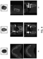
- FIG. 4 is a diagram illustrating the cross-sectional images of teeth that vary depending on the direction of the patient's head
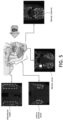
- FIG. 5 is a diagram respectively illustrating detection targets on tooth cross-sectional images in a coronal direction.
- the direction of the patient's head may be divided into an axial plane direction (a), a coronal plane direction (b) and a sagittal plane direction (c), and it can be confirmed that the anatomical sites of teeth appearing in the tooth cross-section images (slices) are different depending on the direction of the head.
- the nerve detection method is characterized in that it generates learning data based on the tooth cross-sectional images in a coronal plane direction (b), which clearly show the anatomical sites such as the mental tubercle, the mental nerve, the inferior alveolar nerve, the alveolar bone, the mandibular angle and the like, and clearly show the distinctions thereof, thereby detecting a nerve based thereon.
- b coronal plane direction
- the inferior alveolar nerve is located inside the alveolar bone, and the mental nerve is not located inside the alveolar bone, but it is in a form pierced outward.
- the step of generating learning data and a learning model S200 generates learning data in which nerves (the mental nerve and the inferior alveolar nerve) and at least one of the mental tubercle and the mandibular angle as a reference for detecting the nerves, and the alveolar bone that helps to detect the inferior alveolar nerve are set in a plurality of acquired learning images, and generates a learning model by learning the learning data.
- nerves the mental nerve and the inferior alveolar nerve
- the alveolar bone that helps to detect the inferior alveolar nerve are set in a plurality of acquired learning images, and generates a learning model by learning the learning data.
- a learning model may be generated by learning the learning data using an algorithm related to a convolutional neural network (CNN) such as U-Net, RCNN and the like, which are stored in the memory 140.
- CNN convolutional neural network
- FIG. 6 is a diagram for describing the method of generating learning data according to an exemplary embodiment of the present invention.
- the learning data may set location and size information for a region (e.g., a box) including the mental tubercle, the mandibular angle and the alveolar bone and nerves (learning targets) for each of a plurality of slices included in the learning image.
- a region e.g., a box
- the x-axis and y-axis positions of the upper left of the box may be set as the position coordinates of the box with the upper left of the learning image as the origin, and the width and height of the box may be set based on the set position coordinates.
- the method of setting the location and size information of the learning targets in the learning image as described above may be applied as it is to the method of setting the position and size information of the detection targets in the target images to be described below.
- the step of detecting a nerve from the target image S400 detects the nerve in the target image based on the learning data.
- the target image may be a 3D image including a plurality of slices (2D cross-sectional images) arranged in a coronal plane direction of the patient.
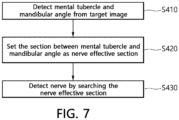
- FIG. 7 is a flowchart of detecting a nerve from the target image of FIG. 6
- FIG. 8 is a diagram for describing the step of detecting a nerve from the target image of FIG. 6 .
- the step of detecting a nerve from the target image S400 detects the mental tubercle and the mandibular angle from the target image based on the learning data S410, sets a section between the detected mental tubercle and mandibular angle as a nerve effective section S420, and detects nerves (the mental nerve and the inferior alveolar nerve) by searching the set nerve effective section S430.
- the detected alveolar bone may be used to detect the inferior alveolar nerve. That is, since the inferior alveolar nerve is located inside the alveolar bone, detection accuracy may be improved by detecting the alveolar bone first and then detecting the inferior alveolar nerve from the detected alveolar bone.
- the meaning of detecting the mental tubercle, the mandibular angle and the alveolar bone and nerves may be interpreted as including the meaning of detecting a slice including these detection targets.
- the step of detecting a nerve from the target image S400 may set a first search starting point S1 based on the statistics of a plurality of learning images, and detect the mental tubercle (MT) by searching in the outer direction of the target image at the set first search starting point S1.
- MT mental tubercle
- a section between the detected mental tubercle (MT) and mandibular angle (MA) may be set as a nerve effective section, and nerves (the mental nerve and the inferior alveolar nerve) may be detected by searching the set nerve effective section.
- the statistics of a plurality of learning images is a value (e.g., 0 to 1) obtained by normalizing the position of anatomical sites included in each image, focusing on the difference in resolution of the captured images for each image acquisition device.
- Statistically there is little likelihood of finding the mental tubercle at the first search starting point (e.g., 0.323) or more, and little likelihood of finding the mandibular angle at the second search starting point (e.g., 0.715) or less. Therefore, if the mental tubercle and the mandibular angle are searched based on the first search starting point and the second search starting point, the mental tubercle and mandibular angle may be searched more quickly and accurately.
- FIG. 9 is a detailed flowchart of detecting a nerve from the target image of FIG. 7 .
- the step of detecting a nerve from a target image S400 sets a target region that is expected to include the mental tubercle, the mandibular angle and nerves, which are detection targets in the corresponding image based on the learning data S431. Then, position and size information of the target region is calculated S432, and a probability value in which the detection target is included in the target region is calculated S433. In addition, a target region having a calculated probability value which is more than or equal to a reference value may be detected as a detection region including the detection target S434, and the detection target may be labeled such that it is displayed in a slice including the corresponding region.
- a neural tube may be finally extracted.
- the nerve detection method detects nerves based on the anatomical characteristics of nerve distribution such that the nerves may be automatically detected more quickly and accurately, and through this, by accurately identifying the location and condition of neural tubes which are different for each patient, it is possible to safely perform implant surgery.
- the nerve detection device may further include a Corrector 154.
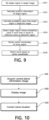
- FIG. 10 is a flowchart of correcting a nerve location according to an exemplary embodiment of the present invention.
- the method for correcting a nerve location is a method of correcting a nerve location previously detected in a 3D image, and may include S500 to S700.
- a 3D image is an image related to a tooth and its surrounding skeletal structure, and the drawings will be illustrated and described assuming that the nerve which is previously detected therefrom is the alveolar nerve (particularly, the inferior alveolar nerve), but the present invention is not limited thereto.
- S500 is an image acquisition step, and it is a step of acquiring a curved planar reformation (CPR) image based on a previously detected nerve location.
- CPR curved planar reformation
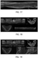
- FIG. 11 illustrates an example of a 3D image indicating nerve locations.
- FIG. 12 illustrates an example of the curved planar reformation image obtained in FIG. 11 .
- the nerve location of the alveolar nerve (C) may be displayed in a separate color for the region in a 3D image.
- curved planar reformation images may be obtained through a process of acquiring curved planar reformation images to be described below based on the nerve location.
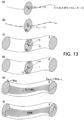
- FIG. 13 illustrates a process of acquiring a curved planar reformation image. Referring to FIG. 13 , the process of acquiring a curved planar reformation image will be described as follows.
- i 0, 1, ... N-1 ⁇ .
- the orthogonal projection vector ( r i ⁇ ) according to the reference vector (r) at each C i may be derived (refer to FIG. 5(c)).
- r i ⁇ is a vector in which r is projected onto P i .
- a plane (hereinafter, referred to as an "orthogonal plane") having a region having C i as a center point and r i ⁇ as a radius on a vertical plane may be derived from P i .
- r is a parameter value for the range for calculating the curved planar reformation image, and it may be preset or input.
- a sample area (S) which is a curved area for a curved planar reformation image
- S a sample area
- CPR curved planar reformation
- the curved planar reformation (CPR) image may be finally obtained according to the cross-sectional direction ( ⁇ ) at each P i in S (refer to FIGS. 13(d) and 13(e) ). That is, ⁇ is a parameter value for the angle of CPR, and it may be preset or input.
- the CPR image is composed of a curved plane constituting C, and may be obtained by C i , r and ⁇ .
- coordinate values constituting CPR are equal to C i + kV i .
- k is a y-axis range-specified scalar value (real number, K ⁇ R 3 ).
- the resolution (the number of samplings) of the CPR image may be determined by the number of C i (N value) and the k value.
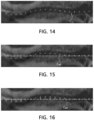
- FIG. 14 shows an example in which nerve locations are displayed on the curved planar reformation image of FIG. 12
- FIG. 15 is a diagram illustrating an example in which nerve locations and reference lines are displayed together in the curved planar reformation image of FIG. 12 .
- S600 is a display step, it is a step of displaying the CPR image acquired in S500, as illustrated in FIG. 12 .
- a nerve location (rhombus) and a reference line (dotted line) may be displayed together on a CPR image.
- points indicating C i may be displayed as the nerve location.
- the reference line is a guide line for correcting the nerve location.
- the alveolar nerve region before correction (C d1 ) (the black area between the upper and lower white areas) and the line of the nerve location (the line connecting the rhombus) displayed on the CPR image must be displayed in a straight line due to the characteristics of the alveolar nerve.
- the line of C d1 and its nerve location appears in a curved form of ' ⁇ .' This indicates that a preset nerve location has been established.
- the reference line provides a reference for correcting the alveolar nerve region (C d1 ) before correction, which is displayed on the CPR image, on the CPR based on the nerve location that is incorrectly set as described above. That is, the shape of the reference line displayed on the CPR may vary depending on the type and shape of the target nerve, and it may be a straight line or curved shape. In particular, when the target nerve is the alveolar nerve, the reference line may be displayed on the CPR image in a straight line by reflecting the shape of the alveolar nerve.
- the coordinate values of the reference line include at least one of the coordinate values of the nerve location. That is, the reference line may be a line passing through a part of the nerve region displayed on the CPR image. Since various types of the reference line are stored, the user may select the reference line through the Iputter 120, and a type designated as a default may be presented.
- the nerve location and the reference line may be displayed on the CPR image in different types of lines, shapes, thicknesses, colors and the like to distinguish the same.
- FIG. 16 illustrates an example of correcting nerve locations displayed in the curved planar reformation image of FIG. 12 along reference lines.
- S700 is a correction step, it is a step of correcting a nerve location, which is displayed on the CPR image, on the CPR image based on the reference line displayed on the CPR image. That is, the point or line of the nerve location displayed on the CPR image may be changed on the CPR image (a part to be changed in FIG. 16 is indicated by an arrow) so as to correspond to the reference line. Accordingly, it is possible to correct by changing the coordinate values of the nerve location of the changed part to the coordinate values of the corresponding part in real time. In this case, the selection of the part to be changed among the nerve locations displayed on the CPR image and the degree of change may be input from the user through the Iputter 120 and performed according to the input data or by various algorithms such as machine learning and the like.
- FIG. 17 illustrates an example of a curved planar reformation image after correction is performed according to FIG. 16 .
- S500 to S700 may be repeatedly performed.
- S500 to S700 may be repeatedly performed based thereon. That is, if the nerve location is corrected by performing S500 to S700 as previous steps, when performing S500 to S700 again later, S500 to S700 may be performed based on the nerve location corrected in the previous step. Through such repetitive performance, the nerve location may be corrected more accurately.
- a CPR image having an angle ( ⁇ 2 ) different from the angle ( ⁇ 1 ) of the previously acquired CPR image may be acquired in S500.
- the selection of ⁇ 2 may be selected according to a predetermined angle change value selected or preset according to the input data received from the user through the Iputter 120 within a certain range ( e.g. , 90° to -90°).
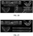
- FIGS. 18 to 21 illustrate various examples of a user interface (UI) that displays curved planar reformation images.
- UI user interface
- a CPR image may be displayed together with a reference image.
- the reference image refers to a 3D image from which a CPR image is derived or an image obtained by processing the corresponding 3D image.
- the CPR image and the reference image may be simultaneously displayed, but the nerve location region may be displayed in the reference image.
- the selection of a specific nerve among a plurality of nerves may be input from the reference image through the Iputter 120, and a CPR image may be obtained based on the input nerve location.
- the selection for the left or right side of the inferior alveolar nerve may be input through the Iputter 120, and S500 may be performed according to the input data such that CPR images based on the corresponding nerve location (left inferior alveolar nerve location or right inferior alveolar nerve location) may be obtained.
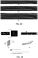
- FIG. 22 illustrates various ranges of curved planar reformation images.
- a range for the CPR image may be input and CPR images reflecting the same may be obtained in S500.
- the range for the CPR image is a value that may be input from the user through the Iputter 120 and may be a value for r and the like.
- various ranges of CPR images may be obtained.
- CPR images reflecting the corresponding range and angle ( ⁇ ) may be displayed in real time in S600.
- the angle ( ⁇ ) or the range for the CPR image may be selected through the Iputter 120.
- the angle ( ⁇ ) or the range may be selected through a mouse wheel manipulation, a mouse drag input, a keyboard direction key input, a keyboard value input for providing a scroll bar on the Display 130 and the like.
- the angle ( ⁇ ) or the range of the CPR image may increase or decrease, according to the operation of the mouse wheel or the input of the direction keys on the keyboard (input with other keys on the keyboard).
- Such an input means has an advantage of providing greater convenience to the user on the above-described UI.
- FIG. 23 is a diagram showing a comparison between the conventional correction method and the method for correcting a nerve location according to an exemplary embodiment of the present invention.
- FIG. 23(a) the movement and correction of the cross-sectional image are performed for the cross-sectional image of a cylinder.
- FIG. 23(b) cross-sectional rotation and correction are performed on the CPR image based on the center point of a cylinder.
- the nerve detection method and device according to the present invention can be used in various fields of dental treatment such as implant surgery and the like.
Landscapes
- Engineering & Computer Science (AREA)
- Health & Medical Sciences (AREA)
- Life Sciences & Earth Sciences (AREA)
- Physics & Mathematics (AREA)
- Medical Informatics (AREA)
- General Health & Medical Sciences (AREA)
- Biomedical Technology (AREA)
- Biophysics (AREA)
- Theoretical Computer Science (AREA)
- Molecular Biology (AREA)
- Animal Behavior & Ethology (AREA)
- Pathology (AREA)
- Veterinary Medicine (AREA)
- Public Health (AREA)
- Surgery (AREA)
- Nuclear Medicine, Radiotherapy & Molecular Imaging (AREA)
- Radiology & Medical Imaging (AREA)
- Heart & Thoracic Surgery (AREA)
- General Physics & Mathematics (AREA)
- Computer Vision & Pattern Recognition (AREA)
- Optics & Photonics (AREA)
- High Energy & Nuclear Physics (AREA)
- Software Systems (AREA)
- Data Mining & Analysis (AREA)
- General Engineering & Computer Science (AREA)
- Computing Systems (AREA)
- Mathematical Physics (AREA)
- Artificial Intelligence (AREA)
- Evolutionary Computation (AREA)
- Neurology (AREA)
- Computational Linguistics (AREA)
- Dentistry (AREA)
- Oral & Maxillofacial Surgery (AREA)
- Quality & Reliability (AREA)
- Physiology (AREA)
- Apparatus For Radiation Diagnosis (AREA)
- Dental Tools And Instruments Or Auxiliary Dental Instruments (AREA)
Claims (15)
- Ein Verfahren zum Erkennen eines Nervs, umfassend:Erfassen eines Lernbilds (S100), das eine Vielzahl von in einer Koronalebenenrichtung angeordneten Schichten umfasst;Erzeugen von Lerndaten, in denen ein Nerv und Tuberculum mentale und/oder ein Mandibularwinkel, die als Referenz zum Erkennen des Nervs dienen, in das Lernbild eingestellt sind, und Lernen der Lerndaten zum Erzeugen eines Lernmodells (S200);Eingeben eines Zielbilds in das Lernmodell (S300);und Erkennen eines Nervs anhand des Zielbilds (S400) auf der Grundlage der Lerndaten.
- Verfahren nach Anspruch 1, wobei das Erkennen eines Nervs anhand des Zielbilds Folgendes umfasst:Erkennen des Tuberculum mentale und Mandibularwinkels anhand des Zielbilds;Festlegen eines Abschnitts zwischen dem erkannten Tuberculum mentale und Mandibularwinkel als einen nervenwirksamen Abschnitt; undErkennen des Nervs durch Durchsuchen des nervenwirksamen Abschnitts.
- Verfahren nach Anspruch 1, wobei das Erzeugen von Lerndaten das Erzeugen von Lerndaten ist, in denen mindestens einer der Alveolarknochen, der Nervus mentalis und der Nervus alveolaris inferior im Lernbild eingestellt ist.
- Verfahren nach Anspruch 3, wobei das Erkennen des Nervs anhand des Zielbilds das Erkennen des Alveolarknochens, des Nervus mentalis und des Nervus alveolaris inferior anhand des Zielbilds ist.
- Verfahren nach Anspruch 4, wobei das Erkennen des Nervus alveolaris inferior das Erkennen des Nervus alveolaris inferior unter Verwendung des erkannten Alveolarknochens ist.
- Verfahren nach Anspruch 2, wobei das Erkennen des Tuberculum mentale anhand des Zielbilds das Erkennen des Tuberculum mentale durch Festlegen eines ersten Suchstartpunkts basierend auf Statistiken des Lernbilds und Suchen in einer äußeren Richtung des Zielbilds vom ersten Suchstartpunkt aus ist.
- Verfahren nach Anspruch 2, wobei das Erkennen des Mandibularwinkels anhand des Zielbilds das Erkennen des Mandibularwinkels durch Festlegen eines zweiten Suchstartpunkts basierend auf Statistiken des Lernbilds und das Suchen in einer äußeren Richtung des Zielbilds vom zweiten Suchstartpunkt aus ist.
- Verfahren nach Anspruch 1, wobei das Erkennen eines Nervs anhand des Zielbilds Folgendes umfasst:Festlegen einer Zielregion, die voraussichtlich das Tuberculum mentale, den Mandibularwinkel und den Nerv beinhaltet, die im Zielbild Erkennungsziele sind;Berechnen von Standort- und Größeninformationen der Zielregion; undBerechnen eines Wahrscheinlichkeitswerts, dass das Erkennungsziel in der Zielregion enthalten ist.
- Verfahren nach Anspruch 8, wobei das Erkennen eines Nervs anhand des Zielbilds ferner das Erkennen der Zielregion umfasst, in der der Wahrscheinlichkeitswert größer oder gleich einem Referenzwert ist, als eine Erkennungsregion, die das Erkennungsziel beinhaltet.
- Verfahren nach Anspruch 9, wobei das Erkennen eines Nervs anhand des Zielbilds ferner umfasst:Extrahieren von Koordinaten einer Region, die den Nerv aus der Erkennungsregion enthält; undErkennen des Nervs basierend auf den Koordinaten.
- Verfahren nach Anspruch 1, ferner umfassend:Erfassen eines gekrümmten planaren Reformations-(CPR-)Bilds basierend auf der Nervenposition;Anzeigen einer Nervenposition und einer Referenzlinie auf dem gekrümmten planaren Reformations-Bild; undKorrigieren der Nervenposition auf dem gekrümmten planaren Reformations-Bild basierend auf der Referenzlinie.
- Verfahren nach Anspruch 11, wobei die Koordinatenwerte der Referenzlinie mindestens einen der Koordinatenwerte der Nervenposition beinhalten.
- Verfahren nach Anspruch 11, wobei die Referenzlinie eine Linie ist, die durch einen Teil einer Nervenregion verläuft, die im gekrümmten planaren Reformations-Bild angezeigt wird.
- Eine Vorrichtung zum Erkennen eines Nervs, umfassend:einen Bildsammler (151) zum Erfassen eines Lernbilds, das eine Vielzahl von in einer Koronalebenenrichtung angeordneten Schichten umfasst;einen Lerner (152) zum Erzeugen von Lerndaten, in denen ein Nerv und Tuberculum mentale und/oder ein Mandibularwinkel, die als Referenz zum Erkennen des Nervs dienen, in das Lernbild eingestellt sind, und Lernen der Lerndaten zum Erzeugen eines Lernmodells; undeinen Nervendetektor (153) zum Erkennen eines Nervs anhand des Zielbilds basierend auf den Lerndaten.
- Vorrichtung nach Anspruch 14, ferner umfassend:
einen Korrektor (154) zum Erfassen eines gekrümmten planaren Reformations-(CPR-)Bilds basierend auf der Nervenposition, zum Anzeigen einer Referenzlinie auf dem gekrümmten planaren Reformations-Bild und zum Korrigieren der Nervenposition basierend auf der Referenzlinie.
Applications Claiming Priority (3)
| Application Number | Priority Date | Filing Date | Title |
|---|---|---|---|
| KR1020190060042A KR102236973B1 (ko) | 2019-05-22 | 2019-05-22 | 신경 검출 방법 및 장치 |
| KR1020190076079A KR102205427B1 (ko) | 2019-06-26 | 2019-06-26 | 신경 위치 보정 방법 및 장치 |
| PCT/KR2020/002757 WO2020235784A1 (ko) | 2019-05-22 | 2020-02-26 | 신경 검출 방법 및 장치 |
Publications (4)
| Publication Number | Publication Date |
|---|---|
| EP3973878A1 EP3973878A1 (de) | 2022-03-30 |
| EP3973878A4 EP3973878A4 (de) | 2023-05-31 |
| EP3973878C0 EP3973878C0 (de) | 2024-12-11 |
| EP3973878B1 true EP3973878B1 (de) | 2024-12-11 |
Family
ID=73458523
Family Applications (1)
| Application Number | Title | Priority Date | Filing Date |
|---|---|---|---|
| EP20809402.9A Active EP3973878B1 (de) | 2019-05-22 | 2020-02-26 | Verfahren und vorrichtung zur nervenerkennung |
Country Status (5)
| Country | Link |
|---|---|
| US (1) | US20220240852A1 (de) |
| EP (1) | EP3973878B1 (de) |
| CN (1) | CN113873947A (de) |
| TW (1) | TWI754259B (de) |
| WO (1) | WO2020235784A1 (de) |
Families Citing this family (3)
| Publication number | Priority date | Publication date | Assignee | Title |
|---|---|---|---|---|
| CN115187596B (zh) * | 2022-09-09 | 2023-02-10 | 中国医学科学院北京协和医院 | 用于腹腔镜结直肠癌手术的神经智能辅助识别系统 |
| WO2025183645A1 (en) * | 2024-02-27 | 2025-09-04 | Sakarya Universitesi Rektorlugu | Decision support method for identification of the sciatic nerve in safe injection practices |
| CN118319489B (zh) * | 2024-06-12 | 2024-08-09 | 吉林大学 | 一种安全距离确定方法、装置、设备及介质 |
Family Cites Families (32)
| Publication number | Priority date | Publication date | Assignee | Title |
|---|---|---|---|---|
| KR100338975B1 (ko) * | 1999-09-14 | 2002-05-31 | 최은백, 이찬경 | 턱뼈의 치조신경 검출방법 |
| US7676022B2 (en) * | 2005-05-02 | 2010-03-09 | Oy Ajat Ltd. | Extra-oral digital panoramic dental x-ray imaging system |
| US9111372B2 (en) * | 2006-08-11 | 2015-08-18 | Visionary Technologies, Inc. | System and method for object identification and anomaly detection |
| DE102008010953A1 (de) * | 2007-02-27 | 2008-10-09 | J.Morita Manufacturing Corp. | Röntgen-CT-Bildanzeigeverfahren, Röntgen-CT-Bildanzeigevorrichtung und Röntgen-CT-Gerät |
| WO2009027889A2 (en) * | 2007-08-31 | 2009-03-05 | Koninklijke Philips Electronics N.V. | Uncertainty maps for segmentation in the presence of metal artifacts |
| CN102036616B (zh) * | 2008-03-21 | 2015-05-13 | 高桥淳 | 三维数字放大镜手术支持系统 |
| DE102012206714A1 (de) * | 2011-08-10 | 2013-02-14 | Friedrich-Alexander-Universität Erlangen-Nürnberg | Verfahren, Recheneinheit, CT-System und C-Bogen-System zur Reduktion von Metallartefakten in CT-Bilddatensätzen |
| KR101666982B1 (ko) * | 2014-12-31 | 2016-10-19 | 오스템임플란트 주식회사 | 치과용 임플란트 플래닝 방법, 이를 위한 장치 및 이를 기록한 기록매체 |
| KR102330616B1 (ko) * | 2016-02-02 | 2021-11-24 | 김도현 | 임플란트 수술 가이드 방법 |
| CN106037874A (zh) * | 2016-05-18 | 2016-10-26 | 四川大学 | 基于下颌骨囊性病变刮治的下牙槽神经保护导板制备方法 |
| KR101908963B1 (ko) * | 2017-07-19 | 2018-12-10 | 주식회사 디오 | 구강 내부 부착용 레퍼런스 마커를 이용한 이미지 처리방법 |
| JP2020525258A (ja) * | 2017-06-30 | 2020-08-27 | プロマトン・ホールディング・ベー・フェー | 深層学習法を使用する3d歯顎顔面構造の分類および3dモデリング |
| FR3069359B1 (fr) * | 2017-07-21 | 2019-08-23 | Dental Monitoring | Procede d'analyse d'une image d'une arcade dentaire |
| KR101839789B1 (ko) * | 2017-08-01 | 2018-03-19 | 주식회사 뷰노 | 치과 영상의 판독 데이터 생성 시스템 |
| EP3462373A1 (de) * | 2017-10-02 | 2019-04-03 | Promaton Holding B.V. | Automatisierte klassifizierung und taxonomie von 3d-zahndaten mit tieflernverfahren |
| US10997727B2 (en) * | 2017-11-07 | 2021-05-04 | Align Technology, Inc. | Deep learning for tooth detection and evaluation |
| TWM562104U (zh) * | 2018-02-02 | 2018-06-21 | Qiu Wen Xin | 具數位顏面影像顯影之口腔齒顎咬合定位裝置 |
| KR101974636B1 (ko) * | 2018-04-18 | 2019-05-03 | 오스템임플란트 주식회사 | 치과용 임플란트 플래닝 방법, 이를 위한 장치, 및 이를 기록한 기록매체 |
| CN108470375B (zh) * | 2018-04-26 | 2022-03-08 | 重庆市劢齐医疗科技有限责任公司 | 一种基于深度学习的神经导管自动检测方法 |
| EP3591616A1 (de) * | 2018-07-03 | 2020-01-08 | Promaton Holding B.V. | Automatisierte bestimmung einer kanonischen lage eines 3d-zahnmodells und überlagerung von 3d-zahnstrukturen mittels tiefenlernen |
| CN109493328B (zh) * | 2018-08-31 | 2020-08-04 | 上海联影智能医疗科技有限公司 | 医学图像显示方法、查看设备以及计算机设备 |
| EP3620130A1 (de) * | 2018-09-04 | 2020-03-11 | Promaton Holding B.V. | Automatische planung zahnmedizinischer behandlungen mit deep learning |
| KR102250164B1 (ko) * | 2018-09-05 | 2021-05-10 | 에이아이메딕(주) | 기계 학습 및 영상 처리 알고리즘을 이용하여 의료 영상의 혈관들을 자동으로 영역화하는 방법 및 시스템 |
| JP7193979B2 (ja) * | 2018-10-29 | 2022-12-21 | 富士フイルムヘルスケア株式会社 | 医用撮像装置、画像処理装置、および、画像処理方法 |
| WO2020105835A1 (ko) * | 2018-11-19 | 2020-05-28 | 주식회사 디오 | 치아 수복물 제조방법 및 제조시스템, 이에 적용되는 범용 왁스바이트 |
| KR102021515B1 (ko) * | 2018-12-27 | 2019-09-16 | (주)제이엘케이인스펙션 | 뇌혈관 질환 학습 장치, 뇌혈관 질환 검출 장치, 뇌혈관 질환 학습 방법 및 뇌혈관 질환 검출 방법 |
| EP3673864B1 (de) * | 2018-12-28 | 2025-10-22 | Nobel Biocare Services AG | Vorrichtung zur erzeugung eines 3d-modellbildes des gebisses eines patienten |
| WO2020171314A1 (ko) * | 2019-02-21 | 2020-08-27 | 주식회사 디오 | 스캔용 왁스바이트 및 이를 이용한 치아 수복물 제조방법 |
| CN109875683B (zh) * | 2019-04-16 | 2020-06-12 | 北京大学第三医院(北京大学第三临床医学院) | 一种下颌角截骨术中建立截骨面预测模型的方法 |
| KR102205427B1 (ko) * | 2019-06-26 | 2021-01-20 | 주식회사 디오 | 신경 위치 보정 방법 및 장치 |
| KR102236973B1 (ko) * | 2019-05-22 | 2021-04-07 | 주식회사 디오 | 신경 검출 방법 및 장치 |
| US11488305B2 (en) * | 2019-10-07 | 2022-11-01 | Nihon University | Segmentation device |
-
2020
- 2020-02-26 CN CN202080036341.8A patent/CN113873947A/zh active Pending
- 2020-02-26 US US17/612,436 patent/US20220240852A1/en not_active Abandoned
- 2020-02-26 WO PCT/KR2020/002757 patent/WO2020235784A1/ko not_active Ceased
- 2020-02-26 EP EP20809402.9A patent/EP3973878B1/de active Active
- 2020-04-17 TW TW109112962A patent/TWI754259B/zh active
Also Published As
| Publication number | Publication date |
|---|---|
| TW202046240A (zh) | 2020-12-16 |
| EP3973878C0 (de) | 2024-12-11 |
| CN113873947A (zh) | 2021-12-31 |
| US20220240852A1 (en) | 2022-08-04 |
| EP3973878A1 (de) | 2022-03-30 |
| EP3973878A4 (de) | 2023-05-31 |
| TWI754259B (zh) | 2022-02-01 |
| WO2020235784A1 (ko) | 2020-11-26 |
Similar Documents
| Publication | Publication Date | Title |
|---|---|---|
| US11302005B2 (en) | Bone cutting support system, information processing apparatus, image processing method, and image processing program | |
| EP3973878B1 (de) | Verfahren und vorrichtung zur nervenerkennung | |
| EP2829218B1 (de) | Bildvervollständigungssystem für einen bildausschnittbereich, bildverarbeitungsvorrichtung und programm dafür | |
| US20160143699A1 (en) | Surgical operation support system, surgical operation support apparatus, surgical operation support method, surgical operation support program, and information processing apparatus | |
| CN112022201A (zh) | 机器引导的成像技术 | |
| US11978203B2 (en) | Dental object detection method, and image matching method and device using dental object | |
| US20220031394A1 (en) | Method and System for Providing Real Time Surgical Site Measurements | |
| US20210205057A1 (en) | Tooth separation systems and methods | |
| JP2019121283A (ja) | 予測モデル生成システム及び予測システム | |
| US11893737B2 (en) | Hinge detection for orthopedic fixation | |
| KR102205427B1 (ko) | 신경 위치 보정 방법 및 장치 | |
| EP4193960B1 (de) | Verfahren zur auswahl eines randlinienpunktes und dentale cad-vorrichtung dafür | |
| EP4140411A1 (de) | Verfahren zur erkennung oraler bildmarker sowie vorrichtung und verfahren zur anpassung oraler bilder damit | |
| KR102322634B1 (ko) | 치아 오브젝트를 이용한 영상 정합 방법 및 장치 | |
| KR20210000942A (ko) | 치아 영상 정합 장치 및 방법 | |
| KR102236973B1 (ko) | 신경 검출 방법 및 장치 | |
| US20230165518A1 (en) | Method and apparatus for predicting missing tooth in oral image | |
| EP3954293A1 (de) | Vorrichtung zur vorverarbeitung von bilddaten | |
| KR20220087874A (ko) | 의료영상 정합 방법 및 그 장치 | |
| KR102161043B1 (ko) | 영상데이터에서 치아를 검출하는 방법 및 장치 | |
| KR102633419B1 (ko) | 증강현실을 이용한 임플란트 수술 가이드 방법 및 이를 수행하기 위한 장치 | |
| KR102277021B1 (ko) | 3차원 구강 ct 영상의 상하악 분리 방법 및 장치 | |
| KR102232043B1 (ko) | 영상데이터에서 치아와 치조골을 분리하는 모델 생성 방법 및 장치 | |
| CN117561579A (zh) | 牙科治疗数据匹配方法及其数字牙科设备 | |
| KR102383546B1 (ko) | 구강 영상 정합 장치 및 방법 |
Legal Events
| Date | Code | Title | Description |
|---|---|---|---|
| STAA | Information on the status of an ep patent application or granted ep patent |
Free format text: STATUS: THE INTERNATIONAL PUBLICATION HAS BEEN MADE |
|
| PUAI | Public reference made under article 153(3) epc to a published international application that has entered the european phase |
Free format text: ORIGINAL CODE: 0009012 |
|
| STAA | Information on the status of an ep patent application or granted ep patent |
Free format text: STATUS: REQUEST FOR EXAMINATION WAS MADE |
|
| 17P | Request for examination filed |
Effective date: 20211118 |
|
| AK | Designated contracting states |
Kind code of ref document: A1 Designated state(s): AL AT BE BG CH CY CZ DE DK EE ES FI FR GB GR HR HU IE IS IT LI LT LU LV MC MK MT NL NO PL PT RO RS SE SI SK SM TR |
|
| DAV | Request for validation of the european patent (deleted) | ||
| DAX | Request for extension of the european patent (deleted) | ||
| A4 | Supplementary search report drawn up and despatched |
Effective date: 20230503 |
|
| RIC1 | Information provided on ipc code assigned before grant |
Ipc: G06N 3/02 20060101ALI20230425BHEP Ipc: A61B 6/14 20060101ALI20230425BHEP Ipc: A61B 34/10 20160101ALI20230425BHEP Ipc: A61B 6/00 20060101AFI20230425BHEP |
|
| GRAP | Despatch of communication of intention to grant a patent |
Free format text: ORIGINAL CODE: EPIDOSNIGR1 |
|
| STAA | Information on the status of an ep patent application or granted ep patent |
Free format text: STATUS: GRANT OF PATENT IS INTENDED |
|
| RIC1 | Information provided on ipc code assigned before grant |
Ipc: A61B 6/51 20240101ALI20240322BHEP Ipc: G06N 20/00 20190101ALI20240322BHEP Ipc: A61B 6/03 20060101ALI20240322BHEP Ipc: A61B 6/50 20240101ALI20240322BHEP Ipc: A61B 6/00 20060101AFI20240322BHEP |
|
| INTG | Intention to grant announced |
Effective date: 20240418 |
|
| GRAS | Grant fee paid |
Free format text: ORIGINAL CODE: EPIDOSNIGR3 |
|
| GRAJ | Information related to disapproval of communication of intention to grant by the applicant or resumption of examination proceedings by the epo deleted |
Free format text: ORIGINAL CODE: EPIDOSDIGR1 |
|
| GRAL | Information related to payment of fee for publishing/printing deleted |
Free format text: ORIGINAL CODE: EPIDOSDIGR3 |
|
| STAA | Information on the status of an ep patent application or granted ep patent |
Free format text: STATUS: REQUEST FOR EXAMINATION WAS MADE |
|
| GRAP | Despatch of communication of intention to grant a patent |
Free format text: ORIGINAL CODE: EPIDOSNIGR1 |
|
| STAA | Information on the status of an ep patent application or granted ep patent |
Free format text: STATUS: GRANT OF PATENT IS INTENDED |
|
| INTC | Intention to grant announced (deleted) | ||
| INTG | Intention to grant announced |
Effective date: 20240918 |
|
| GRAA | (expected) grant |
Free format text: ORIGINAL CODE: 0009210 |
|
| STAA | Information on the status of an ep patent application or granted ep patent |
Free format text: STATUS: THE PATENT HAS BEEN GRANTED |
|
| AK | Designated contracting states |
Kind code of ref document: B1 Designated state(s): AL AT BE BG CH CY CZ DE DK EE ES FI FR GB GR HR HU IE IS IT LI LT LU LV MC MK MT NL NO PL PT RO RS SE SI SK SM TR |
|
| REG | Reference to a national code |
Ref country code: GB Ref legal event code: FG4D |
|
| REG | Reference to a national code |
Ref country code: CH Ref legal event code: EP |
|
| REG | Reference to a national code |
Ref country code: IE Ref legal event code: FG4D |
|
| REG | Reference to a national code |
Ref country code: DE Ref legal event code: R096 Ref document number: 602020043057 Country of ref document: DE |
|
| U01 | Request for unitary effect filed |
Effective date: 20241218 |
|
| U07 | Unitary effect registered |
Designated state(s): AT BE BG DE DK EE FI FR IT LT LU LV MT NL PT RO SE SI Effective date: 20250110 |
|
| PG25 | Lapsed in a contracting state [announced via postgrant information from national office to epo] |
Ref country code: HR Free format text: LAPSE BECAUSE OF FAILURE TO SUBMIT A TRANSLATION OF THE DESCRIPTION OR TO PAY THE FEE WITHIN THE PRESCRIBED TIME-LIMIT Effective date: 20241211 |
|
| PG25 | Lapsed in a contracting state [announced via postgrant information from national office to epo] |
Ref country code: ES Free format text: LAPSE BECAUSE OF FAILURE TO SUBMIT A TRANSLATION OF THE DESCRIPTION OR TO PAY THE FEE WITHIN THE PRESCRIBED TIME-LIMIT Effective date: 20241211 |
|
| PG25 | Lapsed in a contracting state [announced via postgrant information from national office to epo] |
Ref country code: NO Free format text: LAPSE BECAUSE OF FAILURE TO SUBMIT A TRANSLATION OF THE DESCRIPTION OR TO PAY THE FEE WITHIN THE PRESCRIBED TIME-LIMIT Effective date: 20250311 |
|
| PG25 | Lapsed in a contracting state [announced via postgrant information from national office to epo] |
Ref country code: GR Free format text: LAPSE BECAUSE OF FAILURE TO SUBMIT A TRANSLATION OF THE DESCRIPTION OR TO PAY THE FEE WITHIN THE PRESCRIBED TIME-LIMIT Effective date: 20250312 |
|
| PG25 | Lapsed in a contracting state [announced via postgrant information from national office to epo] |
Ref country code: RS Free format text: LAPSE BECAUSE OF FAILURE TO SUBMIT A TRANSLATION OF THE DESCRIPTION OR TO PAY THE FEE WITHIN THE PRESCRIBED TIME-LIMIT Effective date: 20250311 |
|
| PG25 | Lapsed in a contracting state [announced via postgrant information from national office to epo] |
Ref country code: SM Free format text: LAPSE BECAUSE OF FAILURE TO SUBMIT A TRANSLATION OF THE DESCRIPTION OR TO PAY THE FEE WITHIN THE PRESCRIBED TIME-LIMIT Effective date: 20241211 |
|
| PG25 | Lapsed in a contracting state [announced via postgrant information from national office to epo] |
Ref country code: PL Free format text: LAPSE BECAUSE OF FAILURE TO SUBMIT A TRANSLATION OF THE DESCRIPTION OR TO PAY THE FEE WITHIN THE PRESCRIBED TIME-LIMIT Effective date: 20241211 |
|
| PG25 | Lapsed in a contracting state [announced via postgrant information from national office to epo] |
Ref country code: IS Free format text: LAPSE BECAUSE OF FAILURE TO SUBMIT A TRANSLATION OF THE DESCRIPTION OR TO PAY THE FEE WITHIN THE PRESCRIBED TIME-LIMIT Effective date: 20250411 |
|
| PG25 | Lapsed in a contracting state [announced via postgrant information from national office to epo] |
Ref country code: SK Free format text: LAPSE BECAUSE OF FAILURE TO SUBMIT A TRANSLATION OF THE DESCRIPTION OR TO PAY THE FEE WITHIN THE PRESCRIBED TIME-LIMIT Effective date: 20241211 |
|
| PG25 | Lapsed in a contracting state [announced via postgrant information from national office to epo] |
Ref country code: CZ Free format text: LAPSE BECAUSE OF FAILURE TO SUBMIT A TRANSLATION OF THE DESCRIPTION OR TO PAY THE FEE WITHIN THE PRESCRIBED TIME-LIMIT Effective date: 20241211 |
|
| PG25 | Lapsed in a contracting state [announced via postgrant information from national office to epo] |
Ref country code: MC Free format text: LAPSE BECAUSE OF FAILURE TO SUBMIT A TRANSLATION OF THE DESCRIPTION OR TO PAY THE FEE WITHIN THE PRESCRIBED TIME-LIMIT Effective date: 20241211 |
|
| REG | Reference to a national code |
Ref country code: CH Ref legal event code: PL |
|
| U90 | Renewal fees not paid: noting of loss of rights |
Free format text: RENEWAL FEE NOT PAID FOR YEAR 06 Effective date: 20250918 |
|
| PLBE | No opposition filed within time limit |
Free format text: ORIGINAL CODE: 0009261 |
|
| STAA | Information on the status of an ep patent application or granted ep patent |
Free format text: STATUS: NO OPPOSITION FILED WITHIN TIME LIMIT |
|
| PG25 | Lapsed in a contracting state [announced via postgrant information from national office to epo] |
Ref country code: CH Free format text: LAPSE BECAUSE OF NON-PAYMENT OF DUE FEES Effective date: 20250228 |
|
| 26N | No opposition filed |
Effective date: 20250912 |
|
| GBPC | Gb: european patent ceased through non-payment of renewal fee |
Effective date: 20250311 |