EP3972820B1 - Système et procédé pour le traitement de surface sélectif et localisé de pièces, notamment par dépôt de matière - Google Patents
Système et procédé pour le traitement de surface sélectif et localisé de pièces, notamment par dépôt de matière Download PDFInfo
- Publication number
- EP3972820B1 EP3972820B1 EP20735231.1A EP20735231A EP3972820B1 EP 3972820 B1 EP3972820 B1 EP 3972820B1 EP 20735231 A EP20735231 A EP 20735231A EP 3972820 B1 EP3972820 B1 EP 3972820B1
- Authority
- EP
- European Patent Office
- Prior art keywords
- data
- surface treatment
- parts
- treated
- process according
- Prior art date
- Legal status (The legal status is an assumption and is not a legal conclusion. Google has not performed a legal analysis and makes no representation as to the accuracy of the status listed.)
- Active
Links
Images


Classifications
-
- B—PERFORMING OPERATIONS; TRANSPORTING
- B41—PRINTING; LINING MACHINES; TYPEWRITERS; STAMPS
- B41J—TYPEWRITERS; SELECTIVE PRINTING MECHANISMS, i.e. MECHANISMS PRINTING OTHERWISE THAN FROM A FORME; CORRECTION OF TYPOGRAPHICAL ERRORS
- B41J2/00—Typewriters or selective printing mechanisms characterised by the printing or marking process for which they are designed
- B41J2/005—Typewriters or selective printing mechanisms characterised by the printing or marking process for which they are designed characterised by bringing liquid or particles selectively into contact with a printing material
- B41J2/01—Ink jet
-
- B—PERFORMING OPERATIONS; TRANSPORTING
- B29—WORKING OF PLASTICS; WORKING OF SUBSTANCES IN A PLASTIC STATE IN GENERAL
- B29C—SHAPING OR JOINING OF PLASTICS; SHAPING OF MATERIAL IN A PLASTIC STATE, NOT OTHERWISE PROVIDED FOR; AFTER-TREATMENT OF THE SHAPED PRODUCTS, e.g. REPAIRING
- B29C71/00—After-treatment of articles without altering their shape; Apparatus therefor
-
- B—PERFORMING OPERATIONS; TRANSPORTING
- B05—SPRAYING OR ATOMISING IN GENERAL; APPLYING FLUENT MATERIALS TO SURFACES, IN GENERAL
- B05D—PROCESSES FOR APPLYING FLUENT MATERIALS TO SURFACES, IN GENERAL
- B05D3/00—Pretreatment of surfaces to which liquids or other fluent materials are to be applied; After-treatment of applied coatings, e.g. intermediate treating of an applied coating preparatory to subsequent applications of liquids or other fluent materials
- B05D3/06—Pretreatment of surfaces to which liquids or other fluent materials are to be applied; After-treatment of applied coatings, e.g. intermediate treating of an applied coating preparatory to subsequent applications of liquids or other fluent materials by exposure to radiation
- B05D3/061—Pretreatment of surfaces to which liquids or other fluent materials are to be applied; After-treatment of applied coatings, e.g. intermediate treating of an applied coating preparatory to subsequent applications of liquids or other fluent materials by exposure to radiation using U.V.
- B05D3/065—After-treatment
-
- B—PERFORMING OPERATIONS; TRANSPORTING
- B29—WORKING OF PLASTICS; WORKING OF SUBSTANCES IN A PLASTIC STATE IN GENERAL
- B29C—SHAPING OR JOINING OF PLASTICS; SHAPING OF MATERIAL IN A PLASTIC STATE, NOT OTHERWISE PROVIDED FOR; AFTER-TREATMENT OF THE SHAPED PRODUCTS, e.g. REPAIRING
- B29C64/00—Additive manufacturing, i.e. manufacturing of three-dimensional [3D] objects by additive deposition, additive agglomeration or additive layering, e.g. by 3D printing, stereolithography or selective laser sintering
- B29C64/30—Auxiliary operations or equipment
- B29C64/386—Data acquisition or data processing for additive manufacturing
-
- B—PERFORMING OPERATIONS; TRANSPORTING
- B33—ADDITIVE MANUFACTURING TECHNOLOGY
- B33Y—ADDITIVE MANUFACTURING, i.e. MANUFACTURING OF THREE-DIMENSIONAL [3-D] OBJECTS BY ADDITIVE DEPOSITION, ADDITIVE AGGLOMERATION OR ADDITIVE LAYERING, e.g. BY 3-D PRINTING, STEREOLITHOGRAPHY OR SELECTIVE LASER SINTERING
- B33Y40/00—Auxiliary operations or equipment, e.g. for material handling
- B33Y40/20—Post-treatment, e.g. curing, coating or polishing
-
- B—PERFORMING OPERATIONS; TRANSPORTING
- B33—ADDITIVE MANUFACTURING TECHNOLOGY
- B33Y—ADDITIVE MANUFACTURING, i.e. MANUFACTURING OF THREE-DIMENSIONAL [3-D] OBJECTS BY ADDITIVE DEPOSITION, ADDITIVE AGGLOMERATION OR ADDITIVE LAYERING, e.g. BY 3-D PRINTING, STEREOLITHOGRAPHY OR SELECTIVE LASER SINTERING
- B33Y50/00—Data acquisition or data processing for additive manufacturing
-
- B—PERFORMING OPERATIONS; TRANSPORTING
- B41—PRINTING; LINING MACHINES; TYPEWRITERS; STAMPS
- B41J—TYPEWRITERS; SELECTIVE PRINTING MECHANISMS, i.e. MECHANISMS PRINTING OTHERWISE THAN FROM A FORME; CORRECTION OF TYPOGRAPHICAL ERRORS
- B41J11/00—Devices or arrangements of selective printing mechanisms, e.g. ink-jet printers or thermal printers, for supporting or handling copy material in sheet or web form
- B41J11/008—Controlling printhead for accurately positioning print image on printing material, e.g. with the intention to control the width of margins
-
- B—PERFORMING OPERATIONS; TRANSPORTING
- B41—PRINTING; LINING MACHINES; TYPEWRITERS; STAMPS
- B41J—TYPEWRITERS; SELECTIVE PRINTING MECHANISMS, i.e. MECHANISMS PRINTING OTHERWISE THAN FROM A FORME; CORRECTION OF TYPOGRAPHICAL ERRORS
- B41J3/00—Typewriters or selective printing or marking mechanisms characterised by the purpose for which they are constructed
- B41J3/407—Typewriters or selective printing or marking mechanisms characterised by the purpose for which they are constructed for marking on special material
- B41J3/4073—Printing on three-dimensional objects not being in sheet or web form, e.g. spherical or cubic objects
-
- B—PERFORMING OPERATIONS; TRANSPORTING
- B05—SPRAYING OR ATOMISING IN GENERAL; APPLYING FLUENT MATERIALS TO SURFACES, IN GENERAL
- B05D—PROCESSES FOR APPLYING FLUENT MATERIALS TO SURFACES, IN GENERAL
- B05D3/00—Pretreatment of surfaces to which liquids or other fluent materials are to be applied; After-treatment of applied coatings, e.g. intermediate treating of an applied coating preparatory to subsequent applications of liquids or other fluent materials
- B05D3/007—After-treatment
-
- B—PERFORMING OPERATIONS; TRANSPORTING
- B29—WORKING OF PLASTICS; WORKING OF SUBSTANCES IN A PLASTIC STATE IN GENERAL
- B29C—SHAPING OR JOINING OF PLASTICS; SHAPING OF MATERIAL IN A PLASTIC STATE, NOT OTHERWISE PROVIDED FOR; AFTER-TREATMENT OF THE SHAPED PRODUCTS, e.g. REPAIRING
- B29C71/00—After-treatment of articles without altering their shape; Apparatus therefor
- B29C71/0009—After-treatment of articles without altering their shape; Apparatus therefor using liquids, e.g. solvents, swelling agents
-
- B—PERFORMING OPERATIONS; TRANSPORTING
- B29—WORKING OF PLASTICS; WORKING OF SUBSTANCES IN A PLASTIC STATE IN GENERAL
- B29C—SHAPING OR JOINING OF PLASTICS; SHAPING OF MATERIAL IN A PLASTIC STATE, NOT OTHERWISE PROVIDED FOR; AFTER-TREATMENT OF THE SHAPED PRODUCTS, e.g. REPAIRING
- B29C71/00—After-treatment of articles without altering their shape; Apparatus therefor
- B29C71/04—After-treatment of articles without altering their shape; Apparatus therefor by wave energy or particle radiation, e.g. for curing or vulcanising preformed articles
-
- B—PERFORMING OPERATIONS; TRANSPORTING
- B41—PRINTING; LINING MACHINES; TYPEWRITERS; STAMPS
- B41J—TYPEWRITERS; SELECTIVE PRINTING MECHANISMS, i.e. MECHANISMS PRINTING OTHERWISE THAN FROM A FORME; CORRECTION OF TYPOGRAPHICAL ERRORS
- B41J2203/00—Embodiments of or processes related to the control of the printing process
- B41J2203/01—Inspecting a printed medium or a medium to be printed using a sensing device
- B41J2203/011—Inspecting the shape or condition, e.g. wrinkled or warped, of a medium to be printed before printing on it
-
- B—PERFORMING OPERATIONS; TRANSPORTING
- B41—PRINTING; LINING MACHINES; TYPEWRITERS; STAMPS
- B41M—PRINTING, DUPLICATING, MARKING, OR COPYING PROCESSES; COLOUR PRINTING
- B41M5/00—Duplicating or marking methods; Sheet materials for use therein
- B41M5/0082—Digital printing on bodies of particular shapes
- B41M5/0088—Digital printing on bodies of particular shapes by ink-jet printing
-
- B—PERFORMING OPERATIONS; TRANSPORTING
- B41—PRINTING; LINING MACHINES; TYPEWRITERS; STAMPS
- B41M—PRINTING, DUPLICATING, MARKING, OR COPYING PROCESSES; COLOUR PRINTING
- B41M5/00—Duplicating or marking methods; Sheet materials for use therein
- B41M5/24—Ablative recording, e.g. by burning marks; Spark recording
-
- B—PERFORMING OPERATIONS; TRANSPORTING
- B41—PRINTING; LINING MACHINES; TYPEWRITERS; STAMPS
- B41M—PRINTING, DUPLICATING, MARKING, OR COPYING PROCESSES; COLOUR PRINTING
- B41M5/00—Duplicating or marking methods; Sheet materials for use therein
- B41M5/26—Thermography ; Marking by high energetic means, e.g. laser otherwise than by burning, and characterised by the material used
Definitions
- the invention relates to methods for the selective and localized surface treatment of parts by material deposition, and more particularly by inkjet printing. More particularly, the invention relates to a method of surface treatment which comprises a step of selective and localized decoration by depositing ink on zones which will be determined during the execution of the method itself, according to their relief. This process can be used for the decoration of shaped parts having a regular or irregular surface relief, such as a graining, a seam, a joint, a logo, a pattern or an edge.
- Techniques are known for surface treatment of parts by material deposition, for example inkjet printing. These techniques can be used to print images on large surfaces, these surfaces having for example a dimension of the order of a few decimeters to one or two meters. Printing can be done by an inkjet printhead that moves at the end of an arm of a multi-axis robot.
- These systems generally include a system for acquiring the overall shape (flat or curved) of the part on the path which will be the path of the inkjet printing head. They are able to print the image on this flat or curved surface.
- these systems are not suitable for another use, for which they were moreover not designed, namely the selective surface treatment of areas resulting from aspects of local relief, for example bumps, folds, grooves or other aspects.
- Such surface features are found, for example, on surfaces of leather, natural or artificial, where they may be caused by the graining of the leather or by seams.
- the position and the shape of these aspects of local relief is not strictly reproducible from one part to another. When decorating of such a surface by printing, the positioning of the image can become imprecise by this lack of reproducibility of the surface relief.
- the systems according to the state of the art are able to print an image on such surfaces having local aspects, based on the global shape of the part previously acquired, and neglecting the local aspects of the surface; this printing can be of sufficient precision if the printed image does not have to be superimposed on a local relief.
- the systems according to the state of the art are not capable of treating these local surface aspects in a selective manner. For example, they are not capable of selectively depositing ink on stitch marks on a leather surface, or selectively coloring the grain line (i.e. the depression between two grains) of a leather surface.
- leather surface refers here to the surface appearance and not to the material, the chemical nature of which is not important for the problem posed; this leather surface possibly being a surface of artificial leather, such as a plastic material, as is common for example in the field of automobile dashboards.
- the problem that the present invention seeks to solve is to provide a system for treating flat or curved surfaces, which allows the selective surface treatment, for example the selective decoration, of areas of said surface which are inscribed in relief (either in depression or protrusion) on said surface.
- This system must present an offset as low as possible in a direction taken parallel to the plane of the substrate, and an offset as low as possible in the direction perpendicular to the plane of the substrate.
- said surface to be treated has raised surface elements.
- said three-dimensional profilometric data are obtained from a succession of linear scans along scan lines parallel to said direction P, with a constant spacing between two neighboring scan lines, said constant spacing preferably being less to 100 ⁇ m, and even more preferably less than 90 ⁇ m.
- step (c) it is possible to perform at least one digital filtering operation of the data, for example to eliminate outliers.
- said criterion linked to the height of the point of the surface in step (d) assigns the same binary value to all the points located between a minimum height and a maximum height.
- step (d) is repeated to obtain a set of data F3' with a criterion linked to the height of the point on the surface, said criterion being different from that having been used to generate said set of data F3, and two processing operations are carried out according to step (e), namely one for each of the sets of data F 3 and F3′, said processing operations possibly being of identical or different natures.
- the data set F3 is reprocessed to eliminate isolated points of surface treatment, or even to eliminate contiguous zones of surface treatment not reaching a area, or to enlarge contiguous areas of surface treatment, or to round corners of surface treatment area, or to remove holes smaller than a certain number of points inside a surface treatment zone.
- said surface treatment is identical for all the points whose binary value takes said first or second value.
- Said surface treatment may comprise a material deposition step, such as ink deposition, or a material removal step, such as drilling a hole, or a step of chemical modification of the surface, such as a supply of energy capable of cross-linking the surface.
- a material deposition step such as ink deposition
- a material removal step such as drilling a hole
- a step of chemical modification of the surface such as a supply of energy capable of cross-linking the surface.
- a first surface treatment is carried out for the points whose binary data takes said first binary value, then a second surface treatment for the points whose binary value takes said second binary value.
- Another object of the invention is the use of the process according to the invention for the decoration of parts having a regular or irregular surface relief, said surface relief being able to represent in particular a graining, a seam, a joint, an edge, a stamping.
- a final object of the invention is a computer program comprising program code instructions for the execution of the steps of a method according to the invention, when said program operates on a computer machine intended and capable of controlling the activity of a device according to the invention.
- image printing is meant here a process in which a predetermined image, possibly resized in space according to the local geometry, is printed on a surface.
- the selective surface treatment (of which printing represents a particular case), is carried out only on zones selected according to the presence of certain surface aspects, and taking into account their height and/or their depth and/or their precise shape.
- a part having a surface to be treated is supplied.
- the surface to be treated of this part may be curved, typically along a long axis, and/or along a short axis which may or may not be orthogonal with respect to said long axis.
- Said long and short axes can be straight or curved.
- the surface to be treated is typically a zone of a curved surface of the part, for example a longitudinal zone substantially parallel to the long direction of the part. In another embodiment, the surface to be treated is not curved but substantially flat.
- the surface to be treated of the part typically comprises elements in relief, which can extend over all or part of the surface to be treated, and according to any geometric arrangement or shape. These elements in relief can be decorative elements.
- the raised elements may comprise protuberances or depressions. They can be arranged along narrow and elongated lines, or on the contrary extend over a large fraction of the surface to be treated.
- the elements in relief can be represented by false seams, and/or by leather-like graining, and/or or by "crocodile skin", or even by all kinds of stitching, reliefs obtained by any process whatsoever (such as marking, which can be done hot or cold, and/or embossing, which can be done hot or cold), or natural relief.
- the part is advantageously fixed in space in a determined orientation.
- it is placed on a support. If its surface to be treated has a long axis, the part is advantageously oriented so that this long axis is approximately horizontal.
- the part is not fixed but moves during the execution of at least one of the following steps of the method.
- it can be fixed on a mobile carriage capable of moving along a rectilinear path or not, and/or which can be inclined in one or more directions, and/or which can be rotated around at least one axis.
- the part can undergo a rotation around its long axis, if it has such a long axis, and/or it can undergo a rotation around its short axis, if it has such a short axis, and/or it can undergo any other type of rotation, tilt or movement in space.
- profilometry data of the surface to be treated are acquired.
- These profilometry data are three-dimensional data, reconstructed from a succession of two-dimensional linear scans (here called profilometric lines) with a laser beam.
- profilometric lines are parallel to each other, and the spacing between two neighboring lines is advantageously constant.
- profilometry data must first represent the overall three-dimensional shape of the surface to be treated. They must also represent or make it possible to determine, with sufficient three-dimensional resolution, the decorative elements. This minimum resolution depends on the shape of the surface to be treated, the nature and shape of the decorative elements, the scale of length and depth of the decorative elements, and the precision requirement of the treatment of the surface to be to treat.
- This second step can be done for example using a measuring head of a laser scanner which is fixed on a robot arm and which performs one or more scanning passes above the surface to be treated. These passes are advantageously made parallel to the long direction of the part (direction designated here by the letter P).
- data acquisition can be done in one or more passes. More particularly, each pass typically makes it possible to acquire data over an area having a certain width Q in a direction orthogonal to the scan line.
- the data acquisition is made by a succession of individual acquisitions of linear profiles in the direction Q, two successive individual acquisitions being spaced by the same distance in the direction P.
- a three-dimensional profile is constructed from a succession of two-dimensional acquisitions (profilometric lines).
- a first pass in the direction P can make it possible to determine the overall shape of the surface to be treated, and a second pass can then allow data acquisition with a finer resolution of the surface to be treated.
- the distance between the measuring head and the surface advantageously remains constant or varies little (advantageously at most ⁇ 5, preferably at most ⁇ 3 mm, and even more preferably at most ⁇ 2 mm) , and the orientation of the laser beam relative to the surface also remains constant. For this reason, for curved parts, it is advantageous for the measuring head to be fixed to the arm of a five- or six-axis robot.
- the scanning pass is advantageously parallel to this long direction.
- a single scanning pass is performed to analyze a zone of given width Q.
- This second step involves the generation of a first three-dimensional data file of the surface of the part; this file is called here F1. It is built using the data corresponding to the profilometric lines acquired in the Q directions, taken in their succession on the P line.
- This processing may consist of several individual steps. It may include digital filtering. This filtering can be carried out for each profilometric line which has been acquired, and/or for the three-dimensional profile which has been reconstructed from the profilometric lines.
- a digital smoothing is first performed, in a first sub-step, on each profilometric line (for example by appropriate exponential filtering), then the low frequencies are advantageously suppressed (for example by an appropriate high-pass filter), then the adjustment of the profile is carried out (for example by a linear regression); the order of these different processes can be modified, but the order indicated is preferred.
- the three-dimensional profile is processed, for example by a planar regression (calculation of the mean plane), and the aberrant points are removed.
- This processing can for example comprise a filtering of the points according to their standard deviation, and a filtering of the points too far from the plane.
- a fourth step aims to identify or locate on the surface to be treated the areas to be treated. These areas are defined by specific relief features. The areas to which the surface treatment will be applied are therefore determined from the relief of the surface to be treated.
- This step is essential for the process according to the invention. Indeed, in the case of printing on the surface for example, the printing method according to the invention does not consist in printing an image established in advance on a surface; in the context of the method according to the invention, an image is not supplied (for example in the form of a file), but the areas of the surface which will subsequently be treated by the selected surface treatment means are determined during the process itself, depending on the relief of the surface. In other words (and for the example of a surface treatment by inkjet printing), the fine shape of the image printed on the surface depends on the surface itself, it is not fixed from advance.
- This fourth step aims to generate the binary image (file F3) of the surface to be treated.
- This binary image comprises binary information for each point in the plane QP. For each point, said binary information indicates whether a surface treatment will be carried out or not.
- the areas to be treated are bas-reliefs (i.e. hollows) or high-reliefs (i.e. bumps), or even both at the same time.
- a minimum threshold and a maximum height threshold are then adjusted (this height corresponding to "gray level" on an image of the surface), and the points between the minimum threshold and the maximum threshold will be defined as “black” points (i.e. will be subject to surface treatment), and the points above the maximum threshold and below the minimum threshold will be “white” (i.e. will not be subject to surface treatment).
- This determination of the thresholds (for example the difference between the maximum threshold and the minimum threshold) can be the same for different similar parts of the same series, and in particular for parts from the same mold.
- the surface to be treated is treated.
- This treatment typically includes material deposition.
- this surface treatment is done by a surface treatment tool which is fixed on a robot arm and which performs one or more sweeping passes above the surface to be treated, preferably along a trajectory identical to that used. for the acquisition of profilometric data of the part.
- This tool may be an ink jet print head capable of depositing ink.
- the term "ink” means any liquid preparation capable of forming, after drying and/or crosslinking, a solid deposit on a solid substrate; this term encompasses here the inks usually used in inkjet printers, but also varnishes (coloured or not, opaque or transparent) and other products
- This treatment can be done in one or more passes, and one or more inks can be used, for example a colored ink and a transparent or semi-transparent varnish deposited above the colored ink.
- This varnish can have different functions, for example a function of protection against scratches, or a function of modifying the optical properties (anti-reflection function, aesthetic functions such as modification of the gloss, modification of the perceived color), or a function modification of the touch, or even an anti-dirt function.
- a different print head is used for each ink.
- a printing system comprising a robot, a system for determining the zone to be printed and a tool for surface treatment
- a precision of the order of X that is to say that with respect to the shape of the area to be treated the placement deviation of said treatment (for example the placement deviation of the printing) does not exceed a value of X.
- This value of X is advantageously less than 100 ⁇ m, and more advantageously less than 90 ⁇ m.
- a high-resolution printhead is used with a spacing of at least 360 nozzles per inch; such a head can for example comprise a total of 512 nozzles.
- the fine shape of the image printed on the surface depends on the surface itself.
- the method is therefore capable of identifying the areas of the surface to be treated which will be printed.
- the part is a motor vehicle dashboard element having seams, artificial or real, which must be colored
- the accidental absence of a seam point will be recognized by the process , and the missing thread length will not be colored.
- the process according to the printing does not involve the printing of a predefined image, but the selective surface treatment (in this case the coloring) of an area whose identification is part of the process. himself.
- the measuring head 1 schematically shows a measuring head which can be used in the surface treatment device according to the invention. It is typically an optical scanning profilometry, without mechanical contact with the surface to be analyzed. More precisely, the measuring head 1 comprises a laser source 2 (typically a laser diode) which emits a laser beam called incident beam 3 which is directed onto the surface 5 to be analyzed. A sensor 6 detects the reflected beam 7 ; the device typically comprises an optical system 8 comprising at least one lens through which the reflected beam passes.
- This measuring head performs on a line 4 of length Y1 parallel to the direction Y a succession of point measurements, spaced apart by a distance ⁇ Y between two neighboring points; this distance is typically constant.
- FIG. 1 schematically shows a device 10 according to the invention which makes it possible to carry out the method according to the invention.
- This device comprises a robot mounted on a body 17 ; in this example it is a five-axis robot, the axes being identified by the letters A1 to A5 .
- the articulated arm 15 of the robot comprises at its end a gripping arm 16 on which said measuring head 1 and the surface treatment tool can be mounted.
- the part 12 to be treated rests on a support 11 which allows a reproducible and identical positioning of the parts pondered to be identical from the same series.
- the surface 4 to be treated of the part 12 is directed upwards. In this case it is a curved part; the P and Q directions indicated in this figure are explained below in relation to Fig. 3.
- Device 10 is controlled by a programmable computer machine (not shown in the figure).
- computer machine as used here notably includes computers and programmable logic controllers. Said computer machine is intended and able to control the activity of a device 10 according to the invention, and for this purpose it comprises in particular a computer program comprising program code instructions for the execution of the steps of a method according to the invention, when said program runs on said computer machine.
- Said surface treatment tool can be integrated into said measuring head, or can be contained in a box separate from that of said measuring head, which can then be integral with said measuring head.
- the gripping arm 16 alternately apprehends the measuring head and the surface treatment tool, knowing that the measuring head and the surface treatment tool are deposited on a docking station when not in use.
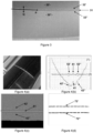
- FIG. 3 shows the photograph of a part treated by the method according to the invention, in this case a trim part of a motor vehicle dashboard.
- This piece includes an area of false seams, which runs parallel to the long direction of the piece.
- the artificial seam of the part comprises two aspects of relief: a central seam 31 , which simulates the connection between two portions 30' , 30" of the part having parallel edges, and two peripheral seams 32' , 32" parallel to said central seam 31 .
- the stitches appear higher in relation to the plane of the part than the central seam.
- the segment Q represents the scanning of the laser beam from the profilometer 1 over each point selected on a line P which corresponds to said central seam 31 .
- This laser beam is shown on the figure 4(a) which is a photograph of a piece similar to that of the figure 4 (but darker in color); we notice on the lower part of the image a ruler calibrated in centimeters which has been placed on part of the surface of the room.
- a three-dimensional data file F1 is thus acquired making it possible to locate the relief in the plane of the surface to be treated, and to quantify for each point in this plane the height or depth with respect to said plane .
- FIG. 4(b) shows the raw profilometric curve corresponding to line Q (curve (1)) obtained at a point on line P, and the same profilometric curve after digital rectification (curve (2)).
- This curve (2) represents the variation in the height of the surface with respect to a base level which corresponds to the curved surface of the part.
- the two peripheral seams 42' , 42" and the central seam 41 are identified on the raw curve (1).
- FIG 4(c) shows an image reconstructed from profilometric measurements carried out successively on several parallel segments Q lying on a certain length of line P. This image is obtained after straightening the profilometric lines, ie from profilometric lines as represented on the Figure 4(b) , curve (2). The data was also filtered.
- the figure 4(c) represents the data of file F2 at the end of the third step of the method according to the invention; the level of gray represents the height relative to said base level. It makes the artificial seams appear in a three-dimensional coding.
- a processing digital that eliminates the center seam.
- This digital processing may involve digital filters taking into account the height relative to the plane of the surface, and/or taking account of the surface morphology.
- FIG. 4(d) shows such a binary image (ie in black and white) obtained from the three-dimensional data of file F2 by appropriate filtering.
- this filtering was designed to eliminate the central seam 31 which was not to be treated by the surface treatment.
- the 72' , 72" lines correspond to the 32' , 32" seams.
- This binary image corresponds to a file F3 of binary data, which indicates for each elementary point whether a surface treatment must be carried out (typically by projection of a drop of ink or varnish) or not.
- the points which constitute this file F3 are preferably defined on a two-dimensional space.
- the height curve obtained on a profilometric line enters the construction of the file F1.
- This file includes for each point in the QP plane a height orthogonal to this plane.
- the file F2 is obtained: the surface can thus be represented by a reconstructed image in which the height is represented as a gray level, like the figure 4(c) .
- the method according to the invention does not directly use this file F2 to carry out the surface treatment by deposition of material, this deposition being carried out by spraying drops of ink or varnish. It is therefore necessary to transform the F2 file, which includes three-dimensional data, with a height value for each point in the QP plane, into an F3 file, in which each point in the QP plane is no longer associated with a height but with a binary value, which indicates the presence or absence of the surface treatment at this point.
- FIG 5 shows a profilometric line after digital rectification, similar to curve (2) of the Figure 4(b) .
- the horizontal axis represents a position on segment Q ( picture 3 ), the vertical axis a height relative to the plane QP.
- This transformation can be done by appropriate filtering. It must be adapted to each type of surface topography.
- the principle of such filtering is illustrated on the figure 5 for the case of false seams. It includes a step in which the surface aspect to be treated is identified. This can be done by clipping, which can be symmetric or non-symmetric (or even one-sided).
- THE Figures 5(a) and 5(b) show two different symmetrical clippings, which do not have the same goal: the clipping of the figure 5(a) aims to identify the central seam 51, with a view to its selective surface treatment, while the clipping of the Figure 5(b) aims to identify the two peripheral seams 52′ , 52′′ , with a view to their selective treatment.
- a threshold Z max and a threshold Z min are fixed so as to select the zone of the central seam 51 , and the height values (vertical axis) are transformed into binary values: “black” for any point on the horizontal axis whose the height value is between Z min and Z max , and "blank” for any bridge on the horizontal axis whose height value is above Z max or below Z min .
- F3 a binary data file
- a point on the profilometric line to which the value "black” has been assigned will then be subjected to the selective surface treatment, whereas a "white” point will not be subjected to said selective surface treatment.
- the values of the thresholds Z min and Z max can be determined automatically, or else manually. It is carried out in particular for the first part of a series of parts reputed to be identical (typically: manufactured in the same mould); indeed, in many cases this determination of the thresholds on a straightened profile makes it possible to process a series of parts reputed to be identical in a stable and reproducible manner. It should be noted that in practice the surface of the parts, even from the same mould, is not completely reproducible, and that these deviations do not make it possible to obtain a satisfactory result by printing an image on the surface according to the state-of-the-art methods.
- a threshold Z′ max lower than the threshold Z max can choose for example a threshold Z′ max lower than the threshold Z max .
- a narrower surface treatment area is thus obtained on the horizontal axis; this is illustrated on the figure 5(c) where the dotted line box represents the width of the area obtained with a lower Z max threshold than the solid line box.
- additional processing is then carried out on the binary file to improve the quality of the surface processing, and in particular the quality of its positioning.
- FIG 6 shows four enlarged photos of stitches colored by the process according to the invention, using gray ink.
- the room is the same as the figures 3 and 4 .
- FIG 7 shows another surface which can be treated by the method according to the invention.
- it is a PVC surface on which was created by embossing a regular relief with "Y" in depression.
- FIG 7(a) shows the relief represented in grayscale (which is a representation of the F2 file)
- the Figure 7(b) shows the binary image (bitmap) which corresponds to file F3, resulting from file F2.
- FIG 8 shows another surface which can be treated by the method according to the invention.
- it is a surface of the “crocodile skin” type, natural or artificial (made for example by embossing on a PVC surface).
- FIG 8(a) shows the relief represented in shades of gray (file F2)
- the figure 8(b) shows the binary image (bitmap) from file F2.
- the surface treatment in this case the deposition of ink
- the process can be applied in the same way to treat zones which are in height by relation to their environment, like the seams of the piece shown on the picture 3 .
- the line of the parallel seams 31,32' , 32" is not a straight line.
- a straight line P can be followed, if the scanning width Q is sufficiently greater to the width necessary to cover the seams and their surroundings on either side of the peripheral seams 32' , 32" .
- the measuring head 1 will follow a straight line P on each of the sections, with a translation in the orthogonal direction between two neighboring sections Alternatively, provision may be made for continuous adaptation of the position of the measuring head 1 during its scanning, but this considerably increases the quantity of digital data to be processed.
- the digital filtering to transform the F1 file into an F2 file can be defined for a series of parts deemed identical, because the local variation between two parts must normally be less than the difference between the reliefs of the central seam and the peripheral seams ; this supposes in practice that each part can be positioned under the head in a reproducible way. It is therefore necessary to have a suitable support for each type of part.
- the method according to the invention can be applied in many sectors of industry. It can be used to decorate trim parts for a land, sea or air vehicle interior. By way of example, it can be used to decorate the surface of car dashboards, and to decorate other visible parts serving as trim in a car interior. It can be used in the leather, leather goods and furniture industry, to decorate natural or artificial leather surfaces, intended for the most diverse uses.
- This decoration may in particular target the visible seams of the decorative parts, which may be artificial (in the case of parts made of plastic material, for example PVC) or functional (in the case of parts made of natural leather). It can also target the graining of grained surfaces, such as the graining of leather or “crocodile skin” type surfaces, or any type of surface relief obtained by technical processes. It can aim more generally at all surface aspects which represent the bottom of a bas-relief or the top of a relief.
- the method according to the invention can be carried out with numerous variants.
- This pre-treatment can be, for example, a corona treatment or a plasma treatment at atmospheric pressure. It can emanate from a specific processing tool, which will then be a pre-processing tool, carried by the arm of the robot, said tool moving over the zone to be pre-processed.
- This material can be a tie layer, or a protective layer. It can for example be transparent, or translucent, and possibly colored, or it can be opaque.
- the surface treatment may aim for decoration and/or protection. It is for example possible to carry out a first decorative surface treatment, in one or more passes, and a second protective surface treatment, in one or more passes. Said first and second surface treatment can be based on the same F3 file or on different F3 files; the second file F3 being able to be obtained for example by digital expansion of the “black” points of the first file F3.
- the same remark applies to the different passes of a decoration and/or protection treatment, which can be strictly superimposed, or the second pass can use dilated points, or even narrowed points, or even an F3 file obtained with a different Z max - Z min thresholding; each of these variants can lead to particular decorative effects, especially if different inks are used. For this purpose more generally any other digital transformation of F3 files is possible.
- a file representing a binary image of the surface is not created in the fourth step, but a ternary or even more complex image.
- the processing by the Z min and Z max thresholds aiming to select the central seam 51 , following the example of the figure 5(a) , and processing by the Z min and Z max thresholds aimed at selecting the peripheral seams 52' , 52" , like the Figure 5(b) of data ; a first fixed value is therefore allocated to the surface treatment points of the central seam, and a second fixed value to the surface treatment points of the peripheral seams, and a third fixed value to the points without surface treatment.
- the two different surface treatments can then be carried out successively with two separate treatment tools, or even with a single treatment tool capable of selectively carrying out two different treatments; such a tool may be an inkjet head capable of projecting ink of two different colors.
- the profilometric data are calculated from images recorded by an optical camera which replaces the measuring head 1 and whose images are analyzed to obtain a binary image of the surface.
- the surface treatment may also include at least one step of transforming the surface by means which do not involve the deposition of material, or it may consist entirely in steps that do not involve the deposition of material.
- said step of transforming the surface by means which do not involve the deposition of material can be: the bombardment of the surface by particles, the irradiation of the surface by a beam of light, the localized supply of heat, the drilling of holes by laser beam.
- These transformation steps may have as their aim in particular the chemical transformation of a surface layer of the material (for example a crosslinking or a hardening by photochemical or thermal means), or its physical transformation (for example by local melting).
Landscapes
- Engineering & Computer Science (AREA)
- Manufacturing & Machinery (AREA)
- Chemical & Material Sciences (AREA)
- Materials Engineering (AREA)
- Physics & Mathematics (AREA)
- Optics & Photonics (AREA)
- Plasma & Fusion (AREA)
- Mechanical Engineering (AREA)
- Application Of Or Painting With Fluid Materials (AREA)
- Printing Methods (AREA)
- Laser Beam Processing (AREA)
- Image Generation (AREA)
- Physical Vapour Deposition (AREA)
- Crystals, And After-Treatments Of Crystals (AREA)
Applications Claiming Priority (2)
| Application Number | Priority Date | Filing Date | Title |
|---|---|---|---|
| FR1905232A FR3096295B1 (fr) | 2019-05-20 | 2019-05-20 | Système et procédé pour le traitement de surface sélectif et localisé de pièces, notamment par dépôt de matière |
| PCT/FR2020/000175 WO2020234517A1 (fr) | 2019-05-20 | 2020-05-19 | Système et procédé pour le traitement de surface sélectif et localisé de pièces, notamment par dépôt de matière |
Publications (2)
| Publication Number | Publication Date |
|---|---|
| EP3972820A1 EP3972820A1 (fr) | 2022-03-30 |
| EP3972820B1 true EP3972820B1 (fr) | 2023-07-12 |
Family
ID=68342982
Family Applications (1)
| Application Number | Title | Priority Date | Filing Date |
|---|---|---|---|
| EP20735231.1A Active EP3972820B1 (fr) | 2019-05-20 | 2020-05-19 | Système et procédé pour le traitement de surface sélectif et localisé de pièces, notamment par dépôt de matière |
Country Status (11)
| Country | Link |
|---|---|
| US (1) | US12053996B2 (pl) |
| EP (1) | EP3972820B1 (pl) |
| JP (1) | JP7619963B2 (pl) |
| KR (1) | KR20220010729A (pl) |
| CN (1) | CN113853306B (pl) |
| ES (1) | ES2953611T3 (pl) |
| FR (1) | FR3096295B1 (pl) |
| MX (1) | MX2021013882A (pl) |
| PL (1) | PL3972820T3 (pl) |
| PT (1) | PT3972820T (pl) |
| WO (1) | WO2020234517A1 (pl) |
Families Citing this family (2)
| Publication number | Priority date | Publication date | Assignee | Title |
|---|---|---|---|---|
| WO2023101682A1 (en) * | 2021-12-03 | 2023-06-08 | Hewlett-Packard Development Company, L.P. | Reducing surface roughness of cured three-dimensional printed objects using a localized heat source |
| ES1306443Y (es) * | 2023-08-01 | 2024-06-10 | Ctdec Europa S L | Complemento de vestir |
Family Cites Families (24)
| Publication number | Priority date | Publication date | Assignee | Title |
|---|---|---|---|---|
| DE602004025099D1 (de) * | 2003-05-07 | 2010-03-04 | Evenzo Ab | Markieren grosser oberflächen mit sichtbaren darstellungen |
| CN103909743B (zh) * | 2007-12-31 | 2017-01-11 | 埃克阿泰克有限责任公司 | 用于打印三维物品的装置和方法 |
| JP2011125835A (ja) | 2009-12-21 | 2011-06-30 | Canon Inc | 画像形成装置およびその制御方法 |
| DE102011082011A1 (de) * | 2011-09-01 | 2013-03-07 | Krones Aktiengesellschaft | Behälter mit bedruckter Oberflächenkontur und Druckverfahren |
| DE102012006371A1 (de) | 2012-03-29 | 2012-07-05 | Heidelberger Druckmaschinen Aktiengesellschaft | Verfahren zum Bedrucken eines Objekts |
| DE102012212469B4 (de) * | 2012-07-17 | 2022-10-06 | Peter Fornoff | Verfahren zum Bedrucken einer Oberfläche und Vorrichtung zum Bedrucken einer Oberfläche |
| DE102012017538A1 (de) | 2012-09-05 | 2014-03-06 | Heidelberger Druckmaschinen Ag | Verfahren zum Bebildern und/oder Lackieren der Oberfläche von Gegenständen |
| EP2973074B1 (en) * | 2013-03-15 | 2019-04-24 | Carnegie Mellon University | A supervised autonomous robotic system for complex surface inspection and processing |
| CN103192612B (zh) * | 2013-04-09 | 2015-09-16 | 中国科学院重庆绿色智能技术研究院 | 基于磁流变材料的3d打印机器人系统及打印方法 |
| JP5612735B1 (ja) * | 2013-07-10 | 2014-10-22 | パナソニック株式会社 | 三次元形状造形物の製造方法およびその製造装置 |
| DE102013107568A1 (de) * | 2013-07-16 | 2015-01-22 | Schultheiss Gmbh | Verfahren und Vorrichtung zum Herstellen eines dreidimensionalen Objekts sowie Belichtungsmaskenerzeugungseinrichtung |
| GB201317974D0 (en) * | 2013-09-19 | 2013-11-27 | Materialise Nv | System and method for calibrating a laser scanning system |
| EP2873496A1 (en) | 2013-11-18 | 2015-05-20 | ABB Technology AG | Printing system |
| CN103700135B (zh) * | 2014-01-08 | 2017-01-04 | 北京科技大学 | 一种三维模型局部球面调和特征提取方法 |
| FR3023943B1 (fr) * | 2014-07-15 | 2017-11-24 | Edm-Ateliers De France | Gravure automatisee d'une surface de mineral en fonction de motifs visuels apparents sur celle-ci |
| EP4530004A3 (en) * | 2014-11-14 | 2025-07-16 | Nikon Corporation | Shaping device and a shaping method |
| KR20160131278A (ko) | 2015-05-06 | 2016-11-16 | 엘지전자 주식회사 | 이동 단말기 |
| CN108463838A (zh) * | 2015-11-16 | 2018-08-28 | 物化股份有限公司 | 增材制造过程中的差错检测 |
| CN105809668B (zh) * | 2016-01-15 | 2018-10-02 | 武汉武大卓越科技有限责任公司 | 基于线扫描三维点云的物体表面变形特征提取方法 |
| JP6758765B2 (ja) | 2016-02-25 | 2020-09-23 | 株式会社ミツトヨ | 測定方法および測定プログラム |
| US11029658B2 (en) * | 2016-09-06 | 2021-06-08 | Continuous Composites Inc. | Systems and methods for controlling additive manufacturing |
| JP6805732B2 (ja) * | 2016-10-31 | 2020-12-23 | オムロン株式会社 | 制御システム、その制御方法および記録媒体 |
| US9975327B1 (en) | 2017-05-18 | 2018-05-22 | Xerox Corporation | System and method for adjusting printhead operations in a direct-to-object printer having a fixed printhead array |
| CN109648202B (zh) * | 2018-08-20 | 2021-02-12 | 南京理工大学 | 非平整面自主识别机器人增材制造成形精度控制方法 |
-
2019
- 2019-05-20 FR FR1905232A patent/FR3096295B1/fr active Active
-
2020
- 2020-05-19 CN CN202080037349.6A patent/CN113853306B/zh active Active
- 2020-05-19 PT PT207352311T patent/PT3972820T/pt unknown
- 2020-05-19 PL PL20735231.1T patent/PL3972820T3/pl unknown
- 2020-05-19 JP JP2021569375A patent/JP7619963B2/ja active Active
- 2020-05-19 WO PCT/FR2020/000175 patent/WO2020234517A1/fr not_active Ceased
- 2020-05-19 EP EP20735231.1A patent/EP3972820B1/fr active Active
- 2020-05-19 US US17/612,596 patent/US12053996B2/en active Active
- 2020-05-19 ES ES20735231T patent/ES2953611T3/es active Active
- 2020-05-19 KR KR1020217040638A patent/KR20220010729A/ko active Pending
- 2020-05-19 MX MX2021013882A patent/MX2021013882A/es unknown
Also Published As
| Publication number | Publication date |
|---|---|
| KR20220010729A (ko) | 2022-01-26 |
| CN113853306B (zh) | 2023-09-12 |
| JP2022536609A (ja) | 2022-08-18 |
| EP3972820A1 (fr) | 2022-03-30 |
| JP7619963B2 (ja) | 2025-01-22 |
| FR3096295A1 (fr) | 2020-11-27 |
| PL3972820T3 (pl) | 2023-09-18 |
| PT3972820T (pt) | 2023-07-19 |
| FR3096295B1 (fr) | 2021-05-14 |
| MX2021013882A (es) | 2022-02-10 |
| ES2953611T3 (es) | 2023-11-14 |
| US20240033995A1 (en) | 2024-02-01 |
| US12053996B2 (en) | 2024-08-06 |
| WO2020234517A1 (fr) | 2020-11-26 |
| CN113853306A (zh) | 2021-12-28 |
Similar Documents
| Publication | Publication Date | Title |
|---|---|---|
| CN105392640B (zh) | 用于在橡胶制品上产生视觉效果的方法和设备 | |
| EP2406085B1 (fr) | Dispositif de marquage adhésif comportant un film support et procédé de réalisation d'un tel dispositif | |
| JP5424910B2 (ja) | 加飾部品の製造方法、部品の加飾方法 | |
| EP3972820B1 (fr) | Système et procédé pour le traitement de surface sélectif et localisé de pièces, notamment par dépôt de matière | |
| EP2903831B1 (fr) | Procédé d'impression d'un marquage par jet d'encre sur une surface | |
| EP2710552B1 (fr) | Methode de determination des marquages en relief presents sur la surface exterieure du flanc d'un pneumatique | |
| EP2856122B1 (fr) | Procede optique d'inspection de recipients transparents ou translucides portant des motifs visuels | |
| FR2730392A1 (fr) | Jeton de jeu et procede de marquage d'un tel jeton | |
| JP5618769B2 (ja) | 樹脂成形体の加飾装置及び加飾方法 | |
| WO2019120933A1 (fr) | Procédé de fabrication d'un cadran comprenant au moins un élément tridimensionnel | |
| JP5377246B2 (ja) | 自動車用加飾部品の製造方法 | |
| EP4334123A1 (en) | A computer-implemented method for determining printing parameter values of an inkjet printing device, a data processing system, a method for inkjet printing and an inkjet printing device and data sets | |
| EP1019255B1 (fr) | Procede de fabrication et de reproduction d'au moins une partie d'un objet ou d'un individu | |
| JP6431351B2 (ja) | 車両の内装用樹脂成形品 | |
| FR3058916A1 (fr) | Procede de traitement de surface d'une piece, installation pour la mise en œuvre dudit procede et piece obtenue par ledit procede de traitement | |
| JP5545626B2 (ja) | 加飾部品の製造方法、部品の加飾方法 | |
| RU2271342C1 (ru) | Способ нанесения декоративного узора на стеклянное зеркало | |
| FR3085619A1 (fr) | Procede d'impression par jet d'encre d'un motif sur une surface en matiere plastique | |
| WO2016056400A1 (ja) | 加飾部品の製造方法 | |
| AU2006201461B2 (en) | Method of printing an image on a metallic surface, particularly on a coin surface | |
| JP2011183289A (ja) | 漆芸法および漆芸品 | |
| FR2896721A1 (fr) | Procede de creation d'un effet decoratif sur support rigide non plan | |
| FR2994402A1 (fr) | Procede de decor sur aeronef et installation pour la mise en oeuvre du procede |
Legal Events
| Date | Code | Title | Description |
|---|---|---|---|
| STAA | Information on the status of an ep patent application or granted ep patent |
Free format text: STATUS: UNKNOWN |
|
| STAA | Information on the status of an ep patent application or granted ep patent |
Free format text: STATUS: THE INTERNATIONAL PUBLICATION HAS BEEN MADE |
|
| PUAI | Public reference made under article 153(3) epc to a published international application that has entered the european phase |
Free format text: ORIGINAL CODE: 0009012 |
|
| STAA | Information on the status of an ep patent application or granted ep patent |
Free format text: STATUS: REQUEST FOR EXAMINATION WAS MADE |
|
| 17P | Request for examination filed |
Effective date: 20211220 |
|
| AK | Designated contracting states |
Kind code of ref document: A1 Designated state(s): AL AT BE BG CH CY CZ DE DK EE ES FI FR GB GR HR HU IE IS IT LI LT LU LV MC MK MT NL NO PL PT RO RS SE SI SK SM TR |
|
| DAV | Request for validation of the european patent (deleted) | ||
| DAX | Request for extension of the european patent (deleted) | ||
| GRAP | Despatch of communication of intention to grant a patent |
Free format text: ORIGINAL CODE: EPIDOSNIGR1 |
|
| STAA | Information on the status of an ep patent application or granted ep patent |
Free format text: STATUS: GRANT OF PATENT IS INTENDED |
|
| RIC1 | Information provided on ipc code assigned before grant |
Ipc: B41M 5/26 20060101ALN20221104BHEP Ipc: B41M 5/24 20060101ALN20221104BHEP Ipc: B29C 71/04 20060101ALN20221104BHEP Ipc: B05D 3/00 20060101ALN20221104BHEP Ipc: B41M 5/00 20060101ALN20221104BHEP Ipc: B05D 3/06 20060101ALI20221104BHEP Ipc: B41J 11/00 20060101ALI20221104BHEP Ipc: B41J 3/407 20060101ALI20221104BHEP Ipc: B29C 71/00 20060101ALI20221104BHEP Ipc: B33Y 50/00 20150101ALI20221104BHEP Ipc: B29C 64/386 20170101AFI20221104BHEP |
|
| RIC1 | Information provided on ipc code assigned before grant |
Ipc: B41M 5/26 20060101ALN20221118BHEP Ipc: B41M 5/24 20060101ALN20221118BHEP Ipc: B29C 71/04 20060101ALN20221118BHEP Ipc: B05D 3/00 20060101ALN20221118BHEP Ipc: B41M 5/00 20060101ALN20221118BHEP Ipc: B05D 3/06 20060101ALI20221118BHEP Ipc: B41J 11/00 20060101ALI20221118BHEP Ipc: B41J 3/407 20060101ALI20221118BHEP Ipc: B29C 71/00 20060101ALI20221118BHEP Ipc: B33Y 50/00 20150101ALI20221118BHEP Ipc: B29C 64/386 20170101AFI20221118BHEP |
|
| INTG | Intention to grant announced |
Effective date: 20221208 |
|
| GRAS | Grant fee paid |
Free format text: ORIGINAL CODE: EPIDOSNIGR3 |
|
| GRAA | (expected) grant |
Free format text: ORIGINAL CODE: 0009210 |
|
| STAA | Information on the status of an ep patent application or granted ep patent |
Free format text: STATUS: THE PATENT HAS BEEN GRANTED |
|
| AK | Designated contracting states |
Kind code of ref document: B1 Designated state(s): AL AT BE BG CH CY CZ DE DK EE ES FI FR GB GR HR HU IE IS IT LI LT LU LV MC MK MT NL NO PL PT RO RS SE SI SK SM TR |
|
| REG | Reference to a national code |
Ref country code: CH Ref legal event code: EP |
|
| REG | Reference to a national code |
Ref country code: PT Ref legal event code: SC4A Ref document number: 3972820 Country of ref document: PT Date of ref document: 20230719 Kind code of ref document: T Free format text: AVAILABILITY OF NATIONAL TRANSLATION Effective date: 20230714 |
|
| REG | Reference to a national code |
Ref country code: RO Ref legal event code: EPE |
|
| REG | Reference to a national code |
Ref country code: IE Ref legal event code: FG4D Free format text: LANGUAGE OF EP DOCUMENT: FRENCH |
|
| REG | Reference to a national code |
Ref country code: DE Ref legal event code: R096 Ref document number: 602020013741 Country of ref document: DE |
|
| P01 | Opt-out of the competence of the unified patent court (upc) registered |
Effective date: 20230712 |
|
| REG | Reference to a national code |
Ref country code: LT Ref legal event code: MG9D |
|
| REG | Reference to a national code |
Ref country code: ES Ref legal event code: FG2A Ref document number: 2953611 Country of ref document: ES Kind code of ref document: T3 Effective date: 20231114 |
|
| REG | Reference to a national code |
Ref country code: NL Ref legal event code: MP Effective date: 20230712 |
|
| PG25 | Lapsed in a contracting state [announced via postgrant information from national office to epo] |
Ref country code: NL Free format text: LAPSE BECAUSE OF FAILURE TO SUBMIT A TRANSLATION OF THE DESCRIPTION OR TO PAY THE FEE WITHIN THE PRESCRIBED TIME-LIMIT Effective date: 20230712 |
|
| REG | Reference to a national code |
Ref country code: AT Ref legal event code: UEP Ref document number: 1586673 Country of ref document: AT Kind code of ref document: T Effective date: 20230712 |
|
| PG25 | Lapsed in a contracting state [announced via postgrant information from national office to epo] |
Ref country code: GR Free format text: LAPSE BECAUSE OF FAILURE TO SUBMIT A TRANSLATION OF THE DESCRIPTION OR TO PAY THE FEE WITHIN THE PRESCRIBED TIME-LIMIT Effective date: 20231013 |
|
| PG25 | Lapsed in a contracting state [announced via postgrant information from national office to epo] |
Ref country code: IS Free format text: LAPSE BECAUSE OF FAILURE TO SUBMIT A TRANSLATION OF THE DESCRIPTION OR TO PAY THE FEE WITHIN THE PRESCRIBED TIME-LIMIT Effective date: 20231112 |
|
| PG25 | Lapsed in a contracting state [announced via postgrant information from national office to epo] |
Ref country code: SE Free format text: LAPSE BECAUSE OF FAILURE TO SUBMIT A TRANSLATION OF THE DESCRIPTION OR TO PAY THE FEE WITHIN THE PRESCRIBED TIME-LIMIT Effective date: 20230712 Ref country code: RS Free format text: LAPSE BECAUSE OF FAILURE TO SUBMIT A TRANSLATION OF THE DESCRIPTION OR TO PAY THE FEE WITHIN THE PRESCRIBED TIME-LIMIT Effective date: 20230712 Ref country code: NO Free format text: LAPSE BECAUSE OF FAILURE TO SUBMIT A TRANSLATION OF THE DESCRIPTION OR TO PAY THE FEE WITHIN THE PRESCRIBED TIME-LIMIT Effective date: 20231012 Ref country code: LV Free format text: LAPSE BECAUSE OF FAILURE TO SUBMIT A TRANSLATION OF THE DESCRIPTION OR TO PAY THE FEE WITHIN THE PRESCRIBED TIME-LIMIT Effective date: 20230712 Ref country code: LT Free format text: LAPSE BECAUSE OF FAILURE TO SUBMIT A TRANSLATION OF THE DESCRIPTION OR TO PAY THE FEE WITHIN THE PRESCRIBED TIME-LIMIT Effective date: 20230712 Ref country code: IS Free format text: LAPSE BECAUSE OF FAILURE TO SUBMIT A TRANSLATION OF THE DESCRIPTION OR TO PAY THE FEE WITHIN THE PRESCRIBED TIME-LIMIT Effective date: 20231112 Ref country code: HR Free format text: LAPSE BECAUSE OF FAILURE TO SUBMIT A TRANSLATION OF THE DESCRIPTION OR TO PAY THE FEE WITHIN THE PRESCRIBED TIME-LIMIT Effective date: 20230712 Ref country code: GR Free format text: LAPSE BECAUSE OF FAILURE TO SUBMIT A TRANSLATION OF THE DESCRIPTION OR TO PAY THE FEE WITHIN THE PRESCRIBED TIME-LIMIT Effective date: 20231013 Ref country code: FI Free format text: LAPSE BECAUSE OF FAILURE TO SUBMIT A TRANSLATION OF THE DESCRIPTION OR TO PAY THE FEE WITHIN THE PRESCRIBED TIME-LIMIT Effective date: 20230712 |
|
| REG | Reference to a national code |
Ref country code: DE Ref legal event code: R097 Ref document number: 602020013741 Country of ref document: DE |
|
| PG25 | Lapsed in a contracting state [announced via postgrant information from national office to epo] |
Ref country code: SM Free format text: LAPSE BECAUSE OF FAILURE TO SUBMIT A TRANSLATION OF THE DESCRIPTION OR TO PAY THE FEE WITHIN THE PRESCRIBED TIME-LIMIT Effective date: 20230712 Ref country code: EE Free format text: LAPSE BECAUSE OF FAILURE TO SUBMIT A TRANSLATION OF THE DESCRIPTION OR TO PAY THE FEE WITHIN THE PRESCRIBED TIME-LIMIT Effective date: 20230712 Ref country code: DK Free format text: LAPSE BECAUSE OF FAILURE TO SUBMIT A TRANSLATION OF THE DESCRIPTION OR TO PAY THE FEE WITHIN THE PRESCRIBED TIME-LIMIT Effective date: 20230712 Ref country code: SK Free format text: LAPSE BECAUSE OF FAILURE TO SUBMIT A TRANSLATION OF THE DESCRIPTION OR TO PAY THE FEE WITHIN THE PRESCRIBED TIME-LIMIT Effective date: 20230712 |
|
| PLBE | No opposition filed within time limit |
Free format text: ORIGINAL CODE: 0009261 |
|
| STAA | Information on the status of an ep patent application or granted ep patent |
Free format text: STATUS: NO OPPOSITION FILED WITHIN TIME LIMIT |
|
| 26N | No opposition filed |
Effective date: 20240415 |
|
| PG25 | Lapsed in a contracting state [announced via postgrant information from national office to epo] |
Ref country code: SI Free format text: LAPSE BECAUSE OF FAILURE TO SUBMIT A TRANSLATION OF THE DESCRIPTION OR TO PAY THE FEE WITHIN THE PRESCRIBED TIME-LIMIT Effective date: 20230712 |
|
| PG25 | Lapsed in a contracting state [announced via postgrant information from national office to epo] |
Ref country code: BG Free format text: LAPSE BECAUSE OF FAILURE TO SUBMIT A TRANSLATION OF THE DESCRIPTION OR TO PAY THE FEE WITHIN THE PRESCRIBED TIME-LIMIT Effective date: 20230712 |
|
| PG25 | Lapsed in a contracting state [announced via postgrant information from national office to epo] |
Ref country code: BG Free format text: LAPSE BECAUSE OF FAILURE TO SUBMIT A TRANSLATION OF THE DESCRIPTION OR TO PAY THE FEE WITHIN THE PRESCRIBED TIME-LIMIT Effective date: 20230712 |
|
| REG | Reference to a national code |
Ref country code: CH Ref legal event code: PL |
|
| PG25 | Lapsed in a contracting state [announced via postgrant information from national office to epo] |
Ref country code: MC Free format text: LAPSE BECAUSE OF FAILURE TO SUBMIT A TRANSLATION OF THE DESCRIPTION OR TO PAY THE FEE WITHIN THE PRESCRIBED TIME-LIMIT Effective date: 20230712 |
|
| PG25 | Lapsed in a contracting state [announced via postgrant information from national office to epo] |
Ref country code: LU Free format text: LAPSE BECAUSE OF NON-PAYMENT OF DUE FEES Effective date: 20240519 |
|
| PG25 | Lapsed in a contracting state [announced via postgrant information from national office to epo] |
Ref country code: MC Free format text: LAPSE BECAUSE OF FAILURE TO SUBMIT A TRANSLATION OF THE DESCRIPTION OR TO PAY THE FEE WITHIN THE PRESCRIBED TIME-LIMIT Effective date: 20230712 Ref country code: LU Free format text: LAPSE BECAUSE OF NON-PAYMENT OF DUE FEES Effective date: 20240519 Ref country code: CH Free format text: LAPSE BECAUSE OF NON-PAYMENT OF DUE FEES Effective date: 20240531 |
|
| REG | Reference to a national code |
Ref country code: BE Ref legal event code: MM Effective date: 20240531 |
|
| PG25 | Lapsed in a contracting state [announced via postgrant information from national office to epo] |
Ref country code: IE Free format text: LAPSE BECAUSE OF NON-PAYMENT OF DUE FEES Effective date: 20240519 |
|
| PG25 | Lapsed in a contracting state [announced via postgrant information from national office to epo] |
Ref country code: BE Free format text: LAPSE BECAUSE OF NON-PAYMENT OF DUE FEES Effective date: 20240531 |
|
| PGFP | Annual fee paid to national office [announced via postgrant information from national office to epo] |
Ref country code: PL Payment date: 20250507 Year of fee payment: 6 Ref country code: DE Payment date: 20250626 Year of fee payment: 6 |
|
| PGFP | Annual fee paid to national office [announced via postgrant information from national office to epo] |
Ref country code: GB Payment date: 20250513 Year of fee payment: 6 |
|
| PGFP | Annual fee paid to national office [announced via postgrant information from national office to epo] |
Ref country code: IT Payment date: 20250528 Year of fee payment: 6 |
|
| PGFP | Annual fee paid to national office [announced via postgrant information from national office to epo] |
Ref country code: PT Payment date: 20250514 Year of fee payment: 6 |
|
| PGFP | Annual fee paid to national office [announced via postgrant information from national office to epo] |
Ref country code: FR Payment date: 20250514 Year of fee payment: 6 |
|
| PGFP | Annual fee paid to national office [announced via postgrant information from national office to epo] |
Ref country code: RO Payment date: 20250505 Year of fee payment: 6 Ref country code: AT Payment date: 20250528 Year of fee payment: 6 |
|
| PGFP | Annual fee paid to national office [announced via postgrant information from national office to epo] |
Ref country code: TR Payment date: 20250512 Year of fee payment: 6 |
|
| PGFP | Annual fee paid to national office [announced via postgrant information from national office to epo] |
Ref country code: CZ Payment date: 20250514 Year of fee payment: 6 |
|
| PG25 | Lapsed in a contracting state [announced via postgrant information from national office to epo] |
Ref country code: CY Free format text: LAPSE BECAUSE OF FAILURE TO SUBMIT A TRANSLATION OF THE DESCRIPTION OR TO PAY THE FEE WITHIN THE PRESCRIBED TIME-LIMIT; INVALID AB INITIO Effective date: 20200519 |
|
| PG25 | Lapsed in a contracting state [announced via postgrant information from national office to epo] |
Ref country code: HU Free format text: LAPSE BECAUSE OF FAILURE TO SUBMIT A TRANSLATION OF THE DESCRIPTION OR TO PAY THE FEE WITHIN THE PRESCRIBED TIME-LIMIT; INVALID AB INITIO Effective date: 20200519 |
|
| PGFP | Annual fee paid to national office [announced via postgrant information from national office to epo] |
Ref country code: ES Payment date: 20250728 Year of fee payment: 6 |