EP3972453B1 - Verbindungsmechanismus mit wandfreiem abstand mit antrieb für elektrisch verstellbaren sitz - Google Patents
Verbindungsmechanismus mit wandfreiem abstand mit antrieb für elektrisch verstellbaren sitz Download PDFInfo
- Publication number
- EP3972453B1 EP3972453B1 EP19929265.7A EP19929265A EP3972453B1 EP 3972453 B1 EP3972453 B1 EP 3972453B1 EP 19929265 A EP19929265 A EP 19929265A EP 3972453 B1 EP3972453 B1 EP 3972453B1
- Authority
- EP
- European Patent Office
- Prior art keywords
- link
- ottoman
- motor
- pivot
- seat
- Prior art date
- Legal status (The legal status is an assumption and is not a legal conclusion. Google has not performed a legal analysis and makes no representation as to the accuracy of the status listed.)
- Active
Links
Images











Classifications
-
- A—HUMAN NECESSITIES
- A47—FURNITURE; DOMESTIC ARTICLES OR APPLIANCES; COFFEE MILLS; SPICE MILLS; SUCTION CLEANERS IN GENERAL
- A47C—CHAIRS; SOFAS; BEDS
- A47C1/00—Chairs adapted for special purposes
- A47C1/02—Reclining or easy chairs
- A47C1/031—Reclining or easy chairs having coupled concurrently adjustable supporting parts
- A47C1/034—Reclining or easy chairs having coupled concurrently adjustable supporting parts the parts including a leg-rest or foot-rest
- A47C1/035—Reclining or easy chairs having coupled concurrently adjustable supporting parts the parts including a leg-rest or foot-rest in combination with movably-coupled seat and back-rest
- A47C1/0355—Reclining or easy chairs having coupled concurrently adjustable supporting parts the parts including a leg-rest or foot-rest in combination with movably-coupled seat and back-rest actuated by linkages, e.g. lazy-tongs mechanisms
-
- A—HUMAN NECESSITIES
- A47—FURNITURE; DOMESTIC ARTICLES OR APPLIANCES; COFFEE MILLS; SPICE MILLS; SUCTION CLEANERS IN GENERAL
- A47C—CHAIRS; SOFAS; BEDS
- A47C1/00—Chairs adapted for special purposes
- A47C1/02—Reclining or easy chairs
- A47C1/031—Reclining or easy chairs having coupled concurrently adjustable supporting parts
- A47C1/032—Reclining or easy chairs having coupled concurrently adjustable supporting parts the parts being movably-coupled seat and back-rest
- A47C1/03205—Reclining or easy chairs having coupled concurrently adjustable supporting parts the parts being movably-coupled seat and back-rest having adjustable and lockable inclination
- A47C1/03211—Reclining or easy chairs having coupled concurrently adjustable supporting parts the parts being movably-coupled seat and back-rest having adjustable and lockable inclination by electric motors
Definitions
- the present invention relates broadly to a seating unit from the field of motion upholstery furniture designed to support a user's body in an essentially seated disposition.
- Motion upholstery furniture includes recliners, incliners, sofas, love seats, sectionals, theater seating, traditional chairs, and chairs with a moveable seat portion, such furniture pieces being referred to herein generally as "seating units.”
- the disclosure relates to an improved metal to the floor, zero-wall linkage mechanism for use on motorized chairs offering an increased seat pitch, and an elevated ottoman in the fully-reclined position. This new fully-reclined position can offer more comfort for users, such as by taking pressure off of a user's back, while still allowing a more-standard reclined position with less seat pitch if desired.
- Reclining seating units exist that allow a user to extend a footrest forward and to recline a backrest rearward relative to a seat.
- These existing seating units typically provide three basic positions (e.g., a standard, non-reclined closed position; an extended position (TV position); and a fully-reclined position).
- the closed position the seat resides in a generally horizontal orientation and the backrest is disposed substantially upright.
- the seating unit includes one or more ottomans that are collapsed or retracted in the closed position, such that the ottomans are not extended.
- the extended position often referred to as a television (“TV”) position, the ottomans are extended forward of the seat, and the backrest remains sufficiently upright to permit comfortable television viewing by an occupant of the seating unit.
- TV television
- US patent application 2008/290710 A1 discloses a seating unit comprising a base; a seat; a backrest; at least one ottoman; a reclining mechanism attached to the base, seat, backrest and ottoman; an ottoman power unit attached to the base and to the reclining mechanism; and a backrest power unit attached to the base and to the reclining mechanism.
- the reclining mechanism is configured to move the seating unit from the upright position to a TV position, in which the ottoman is generally horizontally disposed in front of the seat, and from the TV position to a fully reclined position, in which the backrest is reclined relative to the seat.
- the ottoman power unit is configured to drive the seating unit between the upright and TV positions.
- the backrest power unit is configured to drive the seating unit between the TV and fully reclined positions.
- US patent application 2015/054315 A1 discloses a seating-unit mechanism including various components that control a position of the seat and backrest and that control an extension and retraction of an ottoman and footrest.
- the mechanism includes a linear actuator that controls a seat pitch (e.g., height and level of recline).
- the mechanism includes an ottoman-linkage drive mechanism, which might include a drive link or another linear actuator.
- the seat in the fully-reclined position of these seating units, the seat only slightly drops in the rear, if at all.
- the seat angle from front to back, might drop about eight degrees relative to horizontal.
- This seat pitch might increase slightly in the TV position to about twelve degrees.
- the seat pitch in the fully-reclined position, might increase slightly again to about thirteen degrees. So, in these existing seating units, the seat pitch might change only about five degrees relative to horizontal as the seating unit moves from the closed to the fully-reclined position.
- FIG. 1-15 are not according to the invention:
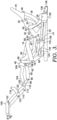
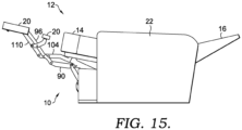
- FIGs. 1-11 illustrate a linkage mechanism 10 for use on a motion seating unit 12 not according to the invention, as shown in FIG. 15 .
- Seating unit 12 has a seat 14, a backrest 16, one or more ottoman(s) 20, and a pair of opposed arms 22.
- the linkage mechanism 10 couples the seat 14, the backrest 16, and the ottoman(s) 20 together to move the seating unit 12 between closed, TV, reclined, and fully-reclined positions, as is more fully described below.
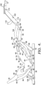
- FIG. 6 depicts the reclined position.
- the backrest 16 is rotated rearward by the linkage mechanism 10.
- the rearward movement of the backrest 16 is offset by a forward and upward translation of the seat 14 as controlled by the linkage mechanism 10.
- the forward and upward translation of the seat 14 in aspects of the present invention allows for "zero-wall" clearance.
- zero-wall clearance is used herein to refer to a space-saving utility that permits positioning the seating unit 12 in close proximity to an adjacent rear wall and other fixed objects.
- the seat 14 may be further angled, and in some aspects the angle of inclination relative to horizontal is about thirteen degrees.
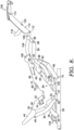
- FIG. 9 illustrates the linkage mechanism 10 in the fully-reclined position. In this position, the height of the ottoman 20 above the support surface increases, such that a user's feet are further above the support surface. Additionally, the seat 14 may be still further angled, and in some aspects the angle of inclination relative to horizontal is in the range of 15-26 degrees. In one aspect, the angle of inclination of the seat, relative to horizontal is about twenty-four degrees.
- the linkage mechanism 10 comprises a plurality of links that are arranged to actuate and control movement of the seating unit 12 during movement between the closed, extended, reclined and fully-reclined positions.
- These links may be pivotally interconnected.
- the pivotal couplings (illustrated as pivot points in the figures) between these links can take a variety of configurations, such as pivot pins, bearings, traditional mounting hardware, rivets, bolt and nut combinations, or any other suitable fasteners, which are well known in the furniture-manufacturing industry.
- the shapes of the links and the brackets may vary, as may the locations of certain pivot points.
- the linkage mechanism 10 guides the coordinated movement of the backrest 16, the seat 14, and the ottoman(s) 20.
- these movements are controlled by a pair of essentially mirror-image linkage mechanisms (one of which is shown herein and indicated by reference numeral 10), which comprise an arrangement of pivotal interconnected linkages.
- the linkage mechanisms 10 are disposed in opposing-facing relation about a longitudinally extending plane that bisects the seating unit 12 between the pair of opposed arms 22.
- the linkage mechanisms 10 are disposed in opposing-facing relation about a longitudinally extending plane that bisects the seating unit 12 between the pair of opposed arms 22.
- FIGS. 1-11 illustrate the configuration of linkage mechanism 10, for a motorized, zero-wall clearance, metal-to-the-floor seating unit 12.
- Linkage mechanism 10 has a pair of parallel, spaced sides, one left and one right, although only one side is shown in the figures for clarity.
- Each side of linkage mechanism 10 includes a side rail 26 that extends from the front of the seating unit 12 to the back. Rails 26 are used to mount the linkage mechanism 10 to the base of the seating unit 12 and operate as the base of the linkage mechanism 10.
- the linkage mechanism 10 on one side of the seating unit includes a first plurality of links, and the linkage mechanism 10 on the other side includes a corresponding second plurality of links.
- a rear pivot link 28 extends upwardly from the rail 26 and is pivotally connected to the rail 26 at a lower end thereof at pivot point 29.
- each of the rails, links, and brackets described herein are typically made of formed or stamped steel, but other materials with similar characteristics could be used.
- Rear pivot link 28 has an outward extension 30 formed generally between its ends that functions to couple a rear cross tube between the left and right mechanisms 10 to provide stability to the linkage mechanism 10.
- the upper end of rear pivot link 28 is pivotally coupled to a rear lift link 32 at pivot 34.
- Rear lift link 32 is also pivotally coupled to a rear control link 36 at pivot 38.
- Rear lift link 32 is also pivotally coupled to a connector link 40 at pivot 42.
- pivot point 42 is located further rearwardly from a forward point 41 of rear lift link 32 than in prior mechanisms, which, in part, allows the linkage mechanism 10 to achieve the fully-reclined position of FIGs. 6-9 .
- rear lift link 32 is pivotally coupled to a seat mounting plate 48 at pivot point 47, as best seen in FIGs. 2 and 4 .
- rear lift link 32 is somewhat triangularly shaped and connects the rear pivot link 28, the rear control link 36, the connector link 40 and the seat mounting plate 48.
- a stop pin 33 is rigidly secured to rear lift link 32 that operates to keep seat mounting plate 48 in position as stop pin 33 contacts a notch formed in seat mounting plate 48.
- Front pivot link 66 is coupled on one end to the front lift link 58 and is pivotally coupled on the opposite, lower end to side rail 26 at pivot 70.
- Front pivot link 66 in some aspects, has an extension 72 that allows for a front cross-tube to be mounted between the pair of front pivot links 66 and couples the linkage mechanisms 10 together for added stability, connecting the two sides together.
- front bell crank 78 has a somewhat boomerang shape, as shown.
- One end of front bell crank 78 is pivotally coupled to carrier link 74 at pivot point 80.
- front bell crank 78 is pivotally coupled to seat mounting plate 48 at pivot 84 (see FIGs. 4 , 9 and 11 ).
- the opposite end of front bell crank 78 is pivotally coupled to an ottoman drive link 86 at pivot 88.
- front bell crank 78 has a stop pin 82 coupled to it just below pivot point 80 that abuts connector link 40 in the closed position.
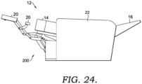
- the linkage mechanism 200 guides the coordinated movement of the backrest 16, the seat 14, and the ottoman(s) 20. In an exemplary configuration, these movements are controlled by a pair of essentially mirror-image linkage mechanisms (one of which is shown herein and indicated by reference numeral 200), which comprise an arrangement of pivotal interconnected linkages.
- the linkage mechanisms 200 are disposed in opposing-facing relation about a longitudinally extending plane that bisects the seating unit 12 between the pair of opposed arms 22. As such, the ensuing discussion will focus on only one of the linkage mechanisms 200, with the content being equally applied to the other complimentary linkage mechanism.
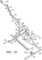
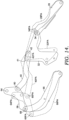
- FIGS. 16-24 illustrate the configuration of linkage mechanism 200, for a motorized, zero-wall clearance, metal-to-the-floor seating unit 12 according to the invention.
- Linkage mechanism 200 has a pair of parallel, spaced sides, one left and one right, although only one side is shown in the figures for clarity.
- Each side of linkage mechanism 200 includes a side rail 202 that extends from the front of the seating unit 12 to the back. Side rails 202 are used to mount the linkage mechanism 200 to the base of the seating unit 12 and operate as the base of the linkage mechanism 200.
- the linkage mechanism 200 on one side of the seating unit includes a first plurality of links, and the linkage mechanism 200 on the other side includes a corresponding second plurality of links.
- a rear pivot link 204 extends upwardly from the side rail 202 and is pivotally connected to the side rail 202 at a lower end thereof at pivot point 206.
- each of the rails, links, and brackets described herein are typically made of formed or stamped steel, but other materials with similar characteristics could be used.
- Rear pivot link 204 has an outward extension 208 formed generally between its ends that functions to couple a rear cross tube between the left and right mechanisms 200 to provide stability to the linkage mechanism 200.
- the upper end of rear pivot link 204 is pivotally coupled to a rear lift link 210 at pivot 212.
- Rear lift link 210 is also pivotally coupled to a rear control link 214 at pivot 216.
- Rear lift link 210 is also pivotally coupled to a connector link 218 at pivot 220.
- pivot point 220 is located further rearwardly from a forward point 222 (see FIG. 21 ) of rear lift link 210 than in prior mechanisms, which, in part, allows the linkage mechanism 200 to achieve the fully-reclined position of FIGs. 21-23 .
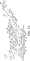
- rear lift link 210 is pivotally coupled to a seat mounting plate 224 at pivot point 226, as best seen in FIGs. 19 and 23 .
- rear lift link 210 is somewhat triangularly shaped and connects the rear pivot link 204, the rear control link 214, the connector link 218 and the seat mounting plate 224. As best seen in FIG.
- a stop pin 228 is rigidly secured to rear lift link 210 that operates to keep seat mounting plate 224 in position as stop pin 228 contacts a notch formed in seat mounting plate 224.
- Seat mounting plate 224 is shaped as shown to facilitate the described connections.
- Seat mounting plate 224 also has a front seat mounting tab 230 and a rear seat mounting tab 232 that form the coupling points to seat 14. In some aspects, the front seat mounting tab 230 and the rear seat mounting tab 232 form a plane that corresponds to the plane of the seat 14.
- the rear control link 214 is coupled on one end to the rear lift link 210 at pivot 216.
- the rear control link 214 extends upwardly, and is pivotally connected to a back mounting link 234 at its other end, at pivot 236.
- Rear control link 214 is thus pivotally connected between rear lift link 210 and back mounting link 234.
- Back mounting link 234 has a forward end that is pivotally coupled to seat mounting plate 224 at pivot 238.
- back mounting link 234 has a lower surface 240 that contacts a stop 242 that is rigidly coupled to seat mounting plate 224.
- the upper end of back mounting link 234 is used to couple the backrest 16 of seating unit 12 to the linkage mechanism 200. As back mounting link 234 pivots rearwardly, the backrest 16 is reclined.
- connector link 218 one end of connector link 218 is pivotally coupled to rear lift link 210 at pivot 220.
- the opposite, forward end of connector link 218 is pivotally coupled to an elongated, front lift link 244 at pivot 246 (see FIG. 21 ).
- connector link 218 has an outward bend section to provide clearance for other links of linkage mechanism 200.
- the outer end of front lift link 244 is pivotally coupled to seat mounting plate 224 at pivot 248.
- the other outer end of front lift link 244 is pivotally coupled to a front pivot link 250 at pivot 252.
- Front lift link 244 is thus pivotally connected to connector link 218, seat mounting plate 224, and front pivot link 250.
- front lift link 244 has a stop pin 254 rigidly secured thereto and extending therefrom.
- Front pivot link 250 is coupled on one end to the front lift link 244 and is pivotally coupled on the opposite, lower end to side rail 202 at pivot 256.
- Front pivot link 250 in some aspects, has an extension 258 that allows for a front cross-tube to be mounted between the pair of front pivot links 250 and couples the linkage mechanisms 200 together for added stability, connecting the two sides together.
- a carrier link 260 is pivotally coupled to front pivot link 250 at pivot 262 generally midway between pivots 252 and 256.
- Carrier link 260 extends from pivot 262 and is coupled on its other end to a front bell crank 264 at pivot 266.
- carrier link 260 has a bend section to provide clearance for the other links of linkage mechanism 200.
- front bell crank 264 has a somewhat boomerang shape, as shown.
- One end of front bell crank 264 is pivotally coupled to carrier link 260 at pivot point 266.
- front bell crank 264 is pivotally coupled to seat mounting plate 224 at pivot 268 (see FIGs. 19 , 22 and 23 ).
- the opposite end of front bell crank 264 is pivotally coupled to an ottoman drive link 270 at pivot 272.
- front bell crank 264 has a stop pin 274 coupled to it just below pivot point 266 that abuts connector link 218 in the closed position.
- front ottoman link 290 is pivotally coupled to seat mounting plate 224 at pivot 294.
- the other end of front ottoman link 290 is pivotally coupled to a lower ottoman link 296 at pivot 298.
- lower ottoman link 296 is pivotally coupled to ottoman bracket assembly 286 at pivot 300 (see FIG. 19 ).
- front ottoman link 290 has a stop pin 302 rigidly secured near pivot 292. Stop pin 302 stops the extension of the ottoman linkage at the desired location.
- the ottoman linkage includes a mid-ottoman, supported by a mid-ottoman bracket 304.
- Mid-ottoman bracket 304 is pivotally coupled to top ottoman link 282 at pivot 306 and is also pivotally coupled to lower ottoman link 296 at pivot 308.
- a lock link 310 is pivotally coupled on an upper end to front ottoman link 290 at pivot 312.
- Lock link 310 extends between front ottoman link 290 and a lock bracket 314.
- Lock link 310 is pivotally coupled to lock bracket 314 at pivot 316.
- the end of lock bracket 314 opposite pivot 316 defines a square opening 318, above which is a mounting tab 320.
- lock bracket 314 also has a stop 321 extending therefrom that abuts a top portion of lock link 310 when the mechanism 200 is in the closed position.
- the mounting tab 320 is used to couple a drive tube 322 to the lock bracket 314.
- the drive tube 322 extends between each mechanism 200 and has a drive tube angle 324 coupled to it, as best seen in FIG. 22 .
- the drive tube angle 324 provides a mounting surface for a pair of drive tube brackets 326.
- Drive tube brackets 326 are coupled to the drive tube angle 324, such as with bolts, weldments or other attaching mechanisms.
- Drive tube brackets 326 have a mounting surface that extends away from the drive tube angle 324.
- a motor drive link 328 is pivotally coupled to each drive tube bracket at pivot 330.
- the motor drive links 328 extend between a respective drive tube bracket 326 and a motor drive bracket 332.
- Each motor drive link 328 is pivotally coupled to a respective motor drive bracket 332 at pivot 334.
- the motor drive brackets 332 are rigidly coupled to a motor guide block 336 that is moveable along a shaft 338 by a motor 340.
- the motor drive brackets 332 have a first section 342 that is coupled to motor guide block 336.
- the motor drive brackets 332 also have a second section 344 that extends rearwardly and slightly upwardly from first section 342. The end of second section 344 is pivotally coupled to motor drive link 328 at pivot 334.
- the motor drive links 328 are longer that prior mechanisms.
- motor drive brackets 332 extend further rearwardly from prior mechanisms, and elevate pivot 334 higher from the underlying support surface.
- the motor drive brackets 332, motor drive links 328 and drive tube brackets 326 form a motor linkage assembly that interconnects the motor guide block 336 to the drive tube 322.
- the motor 340 is mounted between a front cross rail 348 and a rear cross rail 350, offering a different movement feel from mechanism 10 discussed above with respect to FIGs. 1-12 .
- Existing mechanisms do not offer the additional recline shown in FIGs. 21-23 .
- the added recline of FIGs. 21-23 is achievable and does not overstress motor 340.
- the front cross rail 348, rear cross rail 350 and side rails 202 form the base of the metal-to-the-floor linkage mechanism 200.
- the motor 340 can be operated to extend and retract motor guide block 336.
- the linkage formed by motor drive brackets 332, motor drive links 328 and drive tube brackets 326 operates to move drive tube 322.
- lock brackets 314 move lock links 310, thus moving the linkage mechanisms 200 between the closed, TV, reclined and fully reclined positions.
- the motor 340 can be deactivated between the positions shown in FIGs. 16-23 to achieve intermediate positions.
- the motor 340 can be deactivated (stopped) between the TV position shown in FIG. 20 and the fully-reclined position shown in FIG. 23 to achieve a more-standard reclined position (with the ottoman 20 not elevated as far as in FIG. 23 , and the seat 14 not angled as much as in FIG. 23 ).
- the motor 340 can be activated to extend motor guide block 336 when the linkage mechanism 200 is in the closed position of FIGs. 16 and 17 .
- Extension of the motor guide block 336 operates to move the drive tube 322, extending the ottoman bracket assembly 286 to the TV position of FIGs. 18-19 .
- This movement also causes movement of ottoman drive link 270, and causes a rotation of front bell crank 264 about pivot 268, further causing the pivotal connection between front bell crank 264 and ottoman drive link 270 to move forwardly.
- This movement also drives (as viewed from the perspective of FIG. 19 ) a counterclockwise rotation of rear ottoman link 276 about pivot 280.
- the ottoman bracket assembly 286 is moved to the extended position shown in FIG. 19 by the interconnection of links 276, 282, 290, and 296.
- the stop pin 302 prevents over extension of the ottoman linkage.
- the seat mounting plate 224 moves forward, the seat 14 translates forwardly, and the angle of seat mounting plate 224 relative to horizontal increases slightly, as rear lift link 210, connector link 218 and front lift link 244 (along with rear pivot link 204 and front pivot link 250) control the movement and angle of seat mounting plate 224.
- the seat mounting plate 224 (and more specifically the plane formed by front seating mounting tab 230 and rear seat mounting tab 232) moves from an angle of inclination (relative to horizontal) of about eight degrees in the closed position to about twelve degrees in the TV position. In this TV position, the back mounting link 234 remains in substantially the same orientation so that the back 16 remains substantially upright.
- the linkage mechanisms 200 can be stopped in a more-traditional reclined position between the TV position of FIG. 18 and the fully-reclined position of FIG. 23 .
- the motor 340 can further move the linkage mechanisms 200 to the fully-reclined position shown in FIGs. 21-23 .
- the connector link 218 is coupled to rear lift link 210 at pivot 220 in a location that differs from prior seating units.
- the location of pivot 220, and the connection of connector link 218 to front lift link 244 cause the pivot 248 (coupling front lift link 244 to seat mounting plate 224) to lift more that prior seating units.
- the seat mounting plate 224 moves from an angle of inclination (relative to horizontal) of about thirteen degrees in the more-traditional reclined position to about twenty-four degrees in the fully-reclined position, which is not according to the invention.
- the angle of inclination (relative to horizontal) is above eighteen degrees and is up to twenty-six degrees. This additional angle of inclination of the seat 14, along with a corresponding lift in the ottoman 20 has been found to be desirable for some users.
- the ottoman bracket assembly 286 is lifted or elevated further from the underlying support surface, as compared to the more-traditional reclined position. In some aspects, the ottoman bracket assembly 286 is lifted or elevated further from between 10.16cm (four inches) and 17.78cm (seven inches) further from the underlying support surface, as compared to the reclined position.
Landscapes
- Health & Medical Sciences (AREA)
- Dentistry (AREA)
- General Health & Medical Sciences (AREA)
- Chairs For Special Purposes, Such As Reclining Chairs (AREA)
Claims (6)
- Sitzeinheit (12) umfassend:einen Sitz (14);eine Ottomane (20);eine Rückenlehne (16); undeinen Metall-Boden-Verbindungsmechanismus (10; 200), der den Sitz (14), die Ottomane (20) und die Rückenlehne (16) der Sitzeinheit (12) miteinander verbindet,wobei der Metall-Boden-Verbindungsmechanismus (10; 200) eine Rückenlehnenneigung und eine Ottomaneverlängerung für die Sitzeinheit (12) bereitstellt, wobei der Verbindungsmechanismus (10; 200) umfasst:eine Basis mit einer vorderen Querschiene (348), einer hinteren Querschiene (136; 350) und einem Paar beabstandeter Seitenschienen (26; 202);ein Paar beabstandeter, gegenüberliegender Sitzmontageplatten (48; 224), die von der Basis beabstandet sind, wobei das Paar Sitzmontageplatten (48; 224) an dem Sitz (14) der Sitzeinheit (12) anbringbar ist; undeine erste Vielzahl von Verbindungen und eine zweite Vielzahl von Verbindungen, wobei jede der ersten Vielzahl von Verbindungen und der zweiten Vielzahl von Verbindungen schwenkbar zwischen der Basis und einer entsprechenden des Paars Sitzmontageplatten (48; 224) gekoppelt ist, um die Basis und die Sitzmontageplatten (48; 224) bewegbar miteinander zu verbinden, um die Bewegung der Sitzeinheit (12) zwischen geschlossener, TV-, geneigter und vollständig geneigter Position zu steuern; wobei in der vollständig geneigten Position die Sitzmontageplatten (48; 224) durch die erste Vielzahl von Verbindungen und die zweite Vielzahl von Verbindungen in eine Position bewegt werden, um den Sitz (14) der Sitzeinheit (12) in einem Winkel relativ zur Horizontalen von zwischen achtzehn und sechsundzwanzig Grad anzuordnen,wobei der Verbindungsmechanismus ferner umfasst:einen Motor (128; 340), der mit der vorderen Querschiene (348) der Basis gekoppelt ist;eine Welle (134; 338), die sich von dem Motor (128; 340) erstreckt und mit der hinteren Querschiene (136; 350) der Basis gekoppelt ist;einen Motorführungsblock (130; 336), der mit der Welle (134; 338) gekoppelt ist und durch den Motor (128; 340) in Längsrichtung entlang der Welle (134; 338) bewegbar ist;dadurch gekennzeichnet, dass der Verbindungsmechanismus ferner umfasst:ein Antriebsrohr (322), das den Raum zwischen den Sitzmontageplatten (48; 224) überspannt und mit einer der Vielzahl von Verbindungen in jeder der ersten Vielzahl von Verbindungen und der zweiten Vielzahl von Verbindungen gekoppelt ist; undeine Motorverbindungsanordnung (326, 328, 332), die zwischen dem Antriebsrohr (322) und dem Motorführungsblock (130; 336) gekoppelt ist;und dadurch, dass aus der geschlossenen Position eine Betätigung des Motors (128; 340) eine Bewegung des Motorführungsblocks (130; 336) und eine Bewegung des Antriebsrohrs (322) durch die Motorverbindungsanordnung (326, 328, 332) bewirkt, und wobei eine Bewegung des Antriebsrohrs (322) eine Bewegung der Sitzeinheit (12) aus einer geschlossenen Position in eine TV-Position bewirkt, und eine weitere Betätigung des Motors (128; 340) zu einer Bewegung aus der TV-Position in die geneigte Position führt, und eine weitere Betätigung des Motors (128; 340) zu einer Bewegung aus der geneigten Position in die vollständig geneigte Position führt.
- Sitzeinheit (12) nach Anspruch 1, wobei die Motorverbindungsanordnung umfasst:mindestens eine Motorantriebshalterung (330) mit einem ersten Ende und einem zweiten Ende, wobei das erste Ende mit dem Motorführungsblock (336) gekoppelt ist;mindestens eine Motorantriebsverbindung (328) mit einem ersten Ende und einem zweiten Ende, wobei das erste Ende schwenkbar mit dem zweiten Ende der Motorantriebshalterung (330) gekoppelt ist; undmindestens eine Antriebsrohrhalterung (326), die schwenkbar mit dem zweiten Ende der mindestens einen Motorantriebsverbindung (328) gekoppelt ist und fest mit dem Antriebsrohr (322) gekoppelt ist.
- Sitzeinheit (12) nach Anspruch 2, wobei jede der ersten Vielzahl von Verbindungen und der zweiten Vielzahl von Verbindungen umfasst:eine hintere Schwenkverbindung (28; 204) mit einem ersten Ende, das schwenkbar mit einer entsprechenden Seitenschiene (26; 202) des Paars beabstandeter Seitenschienen (26; 202) gekoppelt ist, und mit einem zweiten Ende distal von dem ersten Ende;eine vordere Schwenkverbindung (66; 250) mit einem ersten Ende, das schwenkbar mit der entsprechenden Seitenschiene (26; 202) gekoppelt ist und von der Schwenkverbindung des ersten Endes der hinteren Schwenkverbindung (28; 204) und der entsprechenden Seitenschiene (26; 202) beabstandet ist, und mit einem zweiten Ende distal von dem ersten Ende;eine hintere Hubverbindung (32; 210), die an einem ersten Punkt schwenkbar mit dem zweiten Ende der hinteren Schwenkverbindung (28; 204) gekoppelt ist und an einem zweiten Punkt schwenkbar mit einer entsprechenden der Sitzmontageplatten (48; 224) gekoppelt ist;eine vordere Hubverbindung (58; 244), die an einem ersten Punkt schwenkbar mit dem zweiten Ende der vorderen Schwenkverbindung (66; 250) gekoppelt ist und an einem zweiten Punkt schwenkbar mit einer entsprechenden der Sitzmontageplatten (48; 224) gekoppelt ist; undeine Verbinderverbindung (40; 218), die schwenkbar zwischen der hinteren Hubverbindung (32; 210) und der vorderen Hubverbindung (58; 244) gekoppelt ist.
- Sitzeinheit (12) nach Anspruch 3, wobei die mindestens eine Motorantriebshalterung (332) einen ersten Abschnitt (342), der fest mit dem Motorführungsblock (336) gekoppelt ist, und einen zweiten Abschnitt (344), der schwenkbar mit der mindestens einen Motorantriebsverbindung (328) gekoppelt ist, aufweist, und wobei sich der zweite Abschnitt (344) über und nach hinten von dem ersten Abschnitt (342) erstreckt.
- Sitzeinheit (12) nach Anspruch 3 oder Anspruch 4, wobei die vordere Schwenkverbindung (66; 250), die hintere Schwenkverbindung (28; 204), die hintere Hubverbindung (32; 210), die vordere Hubverbindung (58; 244) und die Verbinderverbindung (40; 218) die Schwenkverbindung der vorderen Hubverbindung (58; 244) und der Sitzmontageplatte (48; 224) über einer Stützfläche um einen größeren Abstand als die Schwenkverbindung der hinteren Hubverbindung (32; 210) und der Sitzmontageplatte (48; 224) über der Stützfläche anheben, wenn sie sich in der vollständig geneigten Position befinden, um den Sitz (14) der Sitzeinheit (12) in einem Winkel relativ zur Horizontalen von zwischen achtzehn und sechsundzwanzig Grad anzuordnen.
- Sitzeinheit (12) nach Anspruch 5, ferner umfassend eine Ottomaneverlängerungsverbindung, die schwenkbar mit der Sitzmontageplatte (48; 224) gekoppelt ist, wobei die Ottomaneverlängerungsverbindung eine Ottomane (20) der Sitzeinheit (12) verlängert, wenn sich der Verbindungsmechanismus (10; 200) von der geschlossenen in die TV-Position bewegt, und wobei in der vollständig geneigten Position die Ottomaneverlängerungsverbindung bewegt wird, um die Ottomane zwischen 10,16 cm (vier Zoll) und 7,78 cm (sieben Zoll) weiter über der Stützfläche relativ zu der Position der Ottomane in der geneigten Position anzuheben.
Applications Claiming Priority (3)
| Application Number | Priority Date | Filing Date | Title |
|---|---|---|---|
| US16/417,165 US10842274B1 (en) | 2019-05-20 | 2019-05-20 | Zero-wall clearance linkage mechanism with power seat drive |
| US16/524,669 US10932570B2 (en) | 2019-05-20 | 2019-07-29 | Zero-wall clearance linkage mechanism with power seat drive |
| PCT/US2019/062462 WO2020236216A1 (en) | 2019-05-20 | 2019-11-20 | Zero-wall clearance linkage mechanism with power seat drive |
Publications (3)
| Publication Number | Publication Date |
|---|---|
| EP3972453A1 EP3972453A1 (de) | 2022-03-30 |
| EP3972453A4 EP3972453A4 (de) | 2023-06-21 |
| EP3972453B1 true EP3972453B1 (de) | 2025-07-09 |
Family
ID=73358193
Family Applications (1)
| Application Number | Title | Priority Date | Filing Date |
|---|---|---|---|
| EP19929265.7A Active EP3972453B1 (de) | 2019-05-20 | 2019-11-20 | Verbindungsmechanismus mit wandfreiem abstand mit antrieb für elektrisch verstellbaren sitz |
Country Status (6)
| Country | Link |
|---|---|
| US (1) | US10932570B2 (de) |
| EP (1) | EP3972453B1 (de) |
| CN (1) | CN111955975B (de) |
| CA (1) | CA3138503C (de) |
| ES (1) | ES3041022T3 (de) |
| WO (1) | WO2020236216A1 (de) |
Families Citing this family (14)
| Publication number | Priority date | Publication date | Assignee | Title |
|---|---|---|---|---|
| US11284721B2 (en) * | 2019-03-29 | 2022-03-29 | L&P Property Management Company | Disengagement and reengagement mechanism on motorized seating unit for selective manual control |
| US11517109B2 (en) | 2019-03-29 | 2022-12-06 | L&P Property Management Company | Disengagement and reengagement mechanism on motorized seating unit for selective manual control |
| CN111671267A (zh) * | 2020-06-05 | 2020-09-18 | 锐迈机械科技(吴江)有限公司 | 一种机械式伸展沙发铁架 |
| CN116194017B (zh) * | 2020-07-30 | 2026-03-06 | L&P产权管理公司 | 机动化座椅单元上的用于选择性手动控制的脱离和重新接合机构 |
| CN214284112U (zh) * | 2020-08-07 | 2021-09-28 | 张孝兆 | 搁脚伸展装置、具有所述搁脚伸展装置的架体及椅子 |
| KR20240004776A (ko) * | 2021-05-31 | 2024-01-11 | 레마크로 머시너리 앤드 테크놀로지(우지앙) 컴퍼니 리미티드 | 등받이 간격 제로를 위한 연동 장치, 브라켓, 좌석 유닛 및 좌석 |
| CN113892772A (zh) * | 2021-10-27 | 2022-01-07 | 锐迈机械科技(吴江)有限公司 | 用于可活动的座椅单元的机械伸展装置及座椅单元 |
| US12082698B2 (en) * | 2022-07-29 | 2024-09-10 | Motomotion China Corporation | Mechanism for zero-gravity reclining chair |
| USD1013489S1 (en) * | 2022-10-03 | 2024-02-06 | Vidaxl Ip B.V. | Lever tool |
| US12022949B2 (en) | 2022-10-13 | 2024-07-02 | Hidden Lake 822, Llc | Drive motor-linear actuator system for powered lift or powered reclining chairs |
| US20240315453A1 (en) * | 2023-03-23 | 2024-09-26 | L&P Property Management Company | High-leg recliner seating mechanism |
| US20240315452A1 (en) * | 2023-03-23 | 2024-09-26 | L&P Property Management Company | High-leg recliner seating mechanism |
| EP4709241A1 (de) * | 2023-05-06 | 2026-03-18 | L & P Property Management Company | Hoor-to-floor-verstellmechanismus mit projiziertem lehnendrehpunkt |
| CN220001288U (zh) * | 2023-05-08 | 2023-11-14 | 海宁和力机械科技有限公司 | 座椅骨架及可切换坐卧姿态的座椅 |
Family Cites Families (46)
| Publication number | Priority date | Publication date | Assignee | Title |
|---|---|---|---|---|
| US5013084A (en) * | 1989-04-06 | 1991-05-07 | Action Industries, Inc. | Mechanism for high-leg reclining chair |
| US7445279B2 (en) * | 2006-11-13 | 2008-11-04 | L & P Property Management Company | Pivot-over-arm reclining mechanism for a seating unit |
| US7766421B2 (en) * | 2006-12-21 | 2010-08-03 | L & P Property Management Company | Recliner lift chair with power lift and reclining units |
| US7673933B2 (en) | 2007-02-15 | 2010-03-09 | Omega Motion L.L.C. | Recliner lift chair with dual motors |
| US7641277B2 (en) * | 2008-01-02 | 2010-01-05 | L & P Property Management Co. | Zero-wall clearance linkage mechanism for a high-leg seating unit |
| US8123289B2 (en) * | 2008-09-24 | 2012-02-28 | I-Trust Better Life Corp | Lift chair and a chair frame with a position holding mechanism for use therewith |
| US8016348B2 (en) * | 2008-11-24 | 2011-09-13 | Ultra-Mek, Inc. | Reciprocating seating unit with power actuator |
| US8113574B2 (en) * | 2008-11-24 | 2012-02-14 | Ultra-Mek, Inc. | Rocking-reclining seating unit with power actuator |
| US7997644B2 (en) * | 2008-11-24 | 2011-08-16 | Ultra-Mek, Inc. | Gliding-reclining seating unit with power actuator |
| US8123288B2 (en) * | 2009-07-24 | 2012-02-28 | Ultra-Mek, Inc. | Locking unit for rocking-reclining seating unit with power actuator |
| US8398168B2 (en) * | 2010-01-15 | 2013-03-19 | L & P Property Management Company | Powered glider recliner linkage mechanism |
| US8398165B2 (en) * | 2010-01-15 | 2013-03-19 | L & P Property Management Company | Powered rocker recliner linkage mechanism |
| US8419122B2 (en) * | 2010-01-25 | 2013-04-16 | L & P Property Management Company | Zero-wall clearance linkage mechanism for a high-leg seating unit |
| US8308228B2 (en) * | 2010-02-11 | 2012-11-13 | L & P Property Management Company | Zero-wall clearance linkage mechanism for a lifting recliner |
| US8449027B2 (en) * | 2010-03-23 | 2013-05-28 | L & P Property Management Company | Full-flat recline linkage |
| US8573687B2 (en) * | 2010-08-27 | 2013-11-05 | L & P Property Management Company | Zero-wall clearance linkage mechanism for providing additional layout |
| US9386857B2 (en) * | 2010-08-27 | 2016-07-12 | L & P Property Management Company | Zero-wall clearance linkage mechanism for providing additional layout |
| US8752890B2 (en) * | 2010-11-03 | 2014-06-17 | Ultra-Mek, Inc. | Reclining seating unit with extendable footrest |
| US8517463B2 (en) * | 2010-11-09 | 2013-08-27 | Ultra-Mek, Inc. | Gliding-reclining layflat seating unit with power actuator and manual and automatic locking linkages |
| US9603453B2 (en) | 2010-12-29 | 2017-03-28 | Ultra-Mek, Inc. | Reclining chair with tilting action to provide heart-rest position |
| US8616626B2 (en) * | 2011-03-14 | 2013-12-31 | L & P Property Management Company | Linkage mechanism for a high-leg seating unit |
| US8696054B2 (en) * | 2011-05-24 | 2014-04-15 | L & P Property Management Company | Enhanced compatibility for a linkage mechanism |
| US8944498B2 (en) * | 2012-01-05 | 2015-02-03 | L & Property Management Company | Linkage mechanism for a dual-motor lifting recliner |
| DE202012102949U1 (de) | 2012-08-06 | 2012-09-03 | Ciar S.P.A. | Antriebssystem mit einem Linearaktuator sowie Möbelstück mit einem solchen Antriebssystem |
| US9241855B2 (en) | 2012-09-12 | 2016-01-26 | La-Z-Boy Incorporated | Furniture member and power recline and lift mechanism |
| US8991925B2 (en) | 2012-09-12 | 2015-03-31 | La-Z-Boy Incorporated | Furniture member and power lift mechanism |
| US9022473B2 (en) * | 2013-05-02 | 2015-05-05 | L&P Property Management Company | Rocker recliner mechanism with changeable features |
| PL2994019T3 (pl) * | 2013-05-10 | 2018-09-28 | L&P Property Man Co | Mechanizm łączący do mebla do siedzenia o wysokich nogach |
| US9844269B2 (en) * | 2013-05-10 | 2017-12-19 | L&P Property Management Company | Motorized linkage mechanism for hi-leg seating unit |
| CN203314484U (zh) * | 2013-05-10 | 2013-12-04 | 常州市锐新医疗器械有限公司 | 电动多连杆摇摆铁架 |
| US9433294B2 (en) | 2013-08-21 | 2016-09-06 | L & P Property Management Company | Reclining and ottoman-extending chair mechanism |
| US9700140B2 (en) | 2013-10-28 | 2017-07-11 | L&P Property Management Company | Zero-wall clearance linkage mechanism including a single drive link |
| CA2975418C (en) | 2014-01-29 | 2018-10-23 | Billy Joe GRIGGS, Jr. | Motor assembly for reclining furniture |
| US10021980B2 (en) * | 2014-07-22 | 2018-07-17 | L&P Property Management Company | Zero-wall clearance linkage mechanism with power seat drive |
| CN204158028U (zh) * | 2014-09-09 | 2015-02-18 | 黄小卫 | 一种活动沙发电动机械伸展装置 |
| US9845852B2 (en) * | 2015-03-20 | 2017-12-19 | L&P Property Management Company | Motorized positioning apparatus for a seating unit |
| US10653243B2 (en) * | 2016-07-29 | 2020-05-19 | Leggett & Platt, Inc. | Rocker/glider recline linkage with projected back pivot point |
| US10420422B2 (en) | 2016-07-29 | 2019-09-24 | L&P Property Management Company | Recliner chair having improved wall clearance and recline linkage with projected back pivot point |
| US10104966B2 (en) * | 2016-07-29 | 2018-10-23 | L&P Property Management Company | Glider recline linkage with double blocker cams |
| US10213020B2 (en) * | 2017-02-24 | 2019-02-26 | L&P Property Management Company | Modular assembly for high leg row seating |
| US10383442B2 (en) * | 2017-02-28 | 2019-08-20 | L&P Property Management Company | Stop mechanism for recliner chair |
| US10881209B2 (en) * | 2018-01-12 | 2021-01-05 | L&P Property Management Company | Recliner seating mechanism with seat extension |
| US10512333B2 (en) * | 2018-03-22 | 2019-12-24 | L&P Property Management Company | Low-profile, zero gravity, all-linkage seat mechanism with added back recline |
| US10575644B2 (en) * | 2018-03-23 | 2020-03-03 | L&P Property Management Company | High-load dual recline mechanism |
| US10820708B2 (en) * | 2018-05-18 | 2020-11-03 | La-Z-Boy Incorporated | Furniture member with wall-proximity mechanism and locking trigger |
| US10897995B2 (en) * | 2018-10-14 | 2021-01-26 | L&P Property Management Company | Pivot-over-arm reclining mechanism for a seating unit and modular seating unit connection system |
-
2019
- 2019-07-29 US US16/524,669 patent/US10932570B2/en active Active
- 2019-11-20 WO PCT/US2019/062462 patent/WO2020236216A1/en not_active Ceased
- 2019-11-20 EP EP19929265.7A patent/EP3972453B1/de active Active
- 2019-11-20 CA CA3138503A patent/CA3138503C/en active Active
- 2019-11-20 ES ES19929265T patent/ES3041022T3/es active Active
-
2020
- 2020-05-06 CN CN202010371607.6A patent/CN111955975B/zh active Active
Also Published As
| Publication number | Publication date |
|---|---|
| CA3138503A1 (en) | 2020-11-26 |
| EP3972453A4 (de) | 2023-06-21 |
| CA3138503C (en) | 2023-12-19 |
| WO2020236216A1 (en) | 2020-11-26 |
| US10932570B2 (en) | 2021-03-02 |
| ES3041022T3 (en) | 2025-11-06 |
| US20200367652A1 (en) | 2020-11-26 |
| EP3972453A1 (de) | 2022-03-30 |
| CN111955975A (zh) | 2020-11-20 |
| CN111955975B (zh) | 2023-12-29 |
Similar Documents
| Publication | Publication Date | Title |
|---|---|---|
| EP3972453B1 (de) | Verbindungsmechanismus mit wandfreiem abstand mit antrieb für elektrisch verstellbaren sitz | |
| US10842274B1 (en) | Zero-wall clearance linkage mechanism with power seat drive | |
| EP3171734B1 (de) | Verbindungsmechanismus mit wandfreiem abstand mit antrieb für elektrisch verstellbaren sitz | |
| US11344123B2 (en) | Pivot-over-arm reclining mechanism for a seating unit and modular seating unit connection system | |
| US9039078B2 (en) | Zero-wall clearance linkage mechanism for a lifting recliner | |
| EP2528474B1 (de) | Verbindungsmechanismus mit wandfreiem freiraum für sitzeinheit zum hochlegen der beine | |
| US8398168B2 (en) | Powered glider recliner linkage mechanism | |
| US12201218B2 (en) | Lift chair mechanism with zero-gravity position options | |
| EP3206534A1 (de) | Ottomanenprofilverbindung |
Legal Events
| Date | Code | Title | Description |
|---|---|---|---|
| STAA | Information on the status of an ep patent application or granted ep patent |
Free format text: STATUS: THE INTERNATIONAL PUBLICATION HAS BEEN MADE |
|
| PUAI | Public reference made under article 153(3) epc to a published international application that has entered the european phase |
Free format text: ORIGINAL CODE: 0009012 |
|
| STAA | Information on the status of an ep patent application or granted ep patent |
Free format text: STATUS: REQUEST FOR EXAMINATION WAS MADE |
|
| 17P | Request for examination filed |
Effective date: 20211207 |
|
| AK | Designated contracting states |
Kind code of ref document: A1 Designated state(s): AL AT BE BG CH CY CZ DE DK EE ES FI FR GB GR HR HU IE IS IT LI LT LU LV MC MK MT NL NO PL PT RO RS SE SI SK SM TR |
|
| DAV | Request for validation of the european patent (deleted) | ||
| DAX | Request for extension of the european patent (deleted) | ||
| A4 | Supplementary search report drawn up and despatched |
Effective date: 20230522 |
|
| RIC1 | Information provided on ipc code assigned before grant |
Ipc: A47C 1/0355 20130101ALI20230515BHEP Ipc: A47C 1/032 20060101AFI20230515BHEP |
|
| P01 | Opt-out of the competence of the unified patent court (upc) registered |
Effective date: 20230523 |
|
| GRAP | Despatch of communication of intention to grant a patent |
Free format text: ORIGINAL CODE: EPIDOSNIGR1 |
|
| STAA | Information on the status of an ep patent application or granted ep patent |
Free format text: STATUS: GRANT OF PATENT IS INTENDED |
|
| INTG | Intention to grant announced |
Effective date: 20240119 |
|
| GRAJ | Information related to disapproval of communication of intention to grant by the applicant or resumption of examination proceedings by the epo deleted |
Free format text: ORIGINAL CODE: EPIDOSDIGR1 |
|
| STAA | Information on the status of an ep patent application or granted ep patent |
Free format text: STATUS: REQUEST FOR EXAMINATION WAS MADE |
|
| STAA | Information on the status of an ep patent application or granted ep patent |
Free format text: STATUS: EXAMINATION IS IN PROGRESS |
|
| INTC | Intention to grant announced (deleted) | ||
| 17Q | First examination report despatched |
Effective date: 20240430 |
|
| GRAP | Despatch of communication of intention to grant a patent |
Free format text: ORIGINAL CODE: EPIDOSNIGR1 |
|
| STAA | Information on the status of an ep patent application or granted ep patent |
Free format text: STATUS: GRANT OF PATENT IS INTENDED |
|
| INTG | Intention to grant announced |
Effective date: 20250318 |
|
| GRAS | Grant fee paid |
Free format text: ORIGINAL CODE: EPIDOSNIGR3 |
|
| GRAA | (expected) grant |
Free format text: ORIGINAL CODE: 0009210 |
|
| STAA | Information on the status of an ep patent application or granted ep patent |
Free format text: STATUS: THE PATENT HAS BEEN GRANTED |
|
| AK | Designated contracting states |
Kind code of ref document: B1 Designated state(s): AL AT BE BG CH CY CZ DE DK EE ES FI FR GB GR HR HU IE IS IT LI LT LU LV MC MK MT NL NO PL PT RO RS SE SI SK SM TR |
|
| REG | Reference to a national code |
Ref country code: GB Ref legal event code: FG4D |
|
| REG | Reference to a national code |
Ref country code: CH Ref legal event code: EP |
|
| REG | Reference to a national code |
Ref country code: IE Ref legal event code: FG4D |
|
| REG | Reference to a national code |
Ref country code: DE Ref legal event code: R096 Ref document number: 602019072485 Country of ref document: DE |
|
| PGFP | Annual fee paid to national office [announced via postgrant information from national office to epo] |
Ref country code: FR Payment date: 20250908 Year of fee payment: 7 |
|
| REG | Reference to a national code |
Ref country code: ES Ref legal event code: FG2A Ref document number: 3041022 Country of ref document: ES Kind code of ref document: T3 Effective date: 20251106 |
|
| REG | Reference to a national code |
Ref country code: NL Ref legal event code: MP Effective date: 20250709 |
|
| PG25 | Lapsed in a contracting state [announced via postgrant information from national office to epo] |
Ref country code: PT Free format text: LAPSE BECAUSE OF FAILURE TO SUBMIT A TRANSLATION OF THE DESCRIPTION OR TO PAY THE FEE WITHIN THE PRESCRIBED TIME-LIMIT Effective date: 20251110 |
|
| PG25 | Lapsed in a contracting state [announced via postgrant information from national office to epo] |
Ref country code: NL Free format text: LAPSE BECAUSE OF FAILURE TO SUBMIT A TRANSLATION OF THE DESCRIPTION OR TO PAY THE FEE WITHIN THE PRESCRIBED TIME-LIMIT Effective date: 20250709 |
|
| REG | Reference to a national code |
Ref country code: AT Ref legal event code: MK05 Ref document number: 1810984 Country of ref document: AT Kind code of ref document: T Effective date: 20250709 |
|
| PG25 | Lapsed in a contracting state [announced via postgrant information from national office to epo] |
Ref country code: IS Free format text: LAPSE BECAUSE OF FAILURE TO SUBMIT A TRANSLATION OF THE DESCRIPTION OR TO PAY THE FEE WITHIN THE PRESCRIBED TIME-LIMIT Effective date: 20251109 |
|
| PGFP | Annual fee paid to national office [announced via postgrant information from national office to epo] |
Ref country code: GB Payment date: 20251001 Year of fee payment: 7 |
|
| PG25 | Lapsed in a contracting state [announced via postgrant information from national office to epo] |
Ref country code: NO Free format text: LAPSE BECAUSE OF FAILURE TO SUBMIT A TRANSLATION OF THE DESCRIPTION OR TO PAY THE FEE WITHIN THE PRESCRIBED TIME-LIMIT Effective date: 20251009 |
|
| REG | Reference to a national code |
Ref country code: LT Ref legal event code: MG9D |
|
| PG25 | Lapsed in a contracting state [announced via postgrant information from national office to epo] |
Ref country code: AT Free format text: LAPSE BECAUSE OF FAILURE TO SUBMIT A TRANSLATION OF THE DESCRIPTION OR TO PAY THE FEE WITHIN THE PRESCRIBED TIME-LIMIT Effective date: 20250709 |
|
| PG25 | Lapsed in a contracting state [announced via postgrant information from national office to epo] |
Ref country code: FI Free format text: LAPSE BECAUSE OF FAILURE TO SUBMIT A TRANSLATION OF THE DESCRIPTION OR TO PAY THE FEE WITHIN THE PRESCRIBED TIME-LIMIT Effective date: 20250709 |
|
| PG25 | Lapsed in a contracting state [announced via postgrant information from national office to epo] |
Ref country code: HR Free format text: LAPSE BECAUSE OF FAILURE TO SUBMIT A TRANSLATION OF THE DESCRIPTION OR TO PAY THE FEE WITHIN THE PRESCRIBED TIME-LIMIT Effective date: 20250709 |
|
| PG25 | Lapsed in a contracting state [announced via postgrant information from national office to epo] |
Ref country code: GR Free format text: LAPSE BECAUSE OF FAILURE TO SUBMIT A TRANSLATION OF THE DESCRIPTION OR TO PAY THE FEE WITHIN THE PRESCRIBED TIME-LIMIT Effective date: 20251010 |
|
| PG25 | Lapsed in a contracting state [announced via postgrant information from national office to epo] |
Ref country code: SE Free format text: LAPSE BECAUSE OF FAILURE TO SUBMIT A TRANSLATION OF THE DESCRIPTION OR TO PAY THE FEE WITHIN THE PRESCRIBED TIME-LIMIT Effective date: 20250709 |
|
| PG25 | Lapsed in a contracting state [announced via postgrant information from national office to epo] |
Ref country code: LV Free format text: LAPSE BECAUSE OF FAILURE TO SUBMIT A TRANSLATION OF THE DESCRIPTION OR TO PAY THE FEE WITHIN THE PRESCRIBED TIME-LIMIT Effective date: 20250709 |
|
| PG25 | Lapsed in a contracting state [announced via postgrant information from national office to epo] |
Ref country code: BG Free format text: LAPSE BECAUSE OF FAILURE TO SUBMIT A TRANSLATION OF THE DESCRIPTION OR TO PAY THE FEE WITHIN THE PRESCRIBED TIME-LIMIT Effective date: 20250709 Ref country code: PL Free format text: LAPSE BECAUSE OF FAILURE TO SUBMIT A TRANSLATION OF THE DESCRIPTION OR TO PAY THE FEE WITHIN THE PRESCRIBED TIME-LIMIT Effective date: 20250709 |
|
| PG25 | Lapsed in a contracting state [announced via postgrant information from national office to epo] |
Ref country code: RS Free format text: LAPSE BECAUSE OF FAILURE TO SUBMIT A TRANSLATION OF THE DESCRIPTION OR TO PAY THE FEE WITHIN THE PRESCRIBED TIME-LIMIT Effective date: 20251009 |
|
| PGFP | Annual fee paid to national office [announced via postgrant information from national office to epo] |
Ref country code: ES Payment date: 20251212 Year of fee payment: 7 |
|
| PG25 | Lapsed in a contracting state [announced via postgrant information from national office to epo] |
Ref country code: RO Free format text: LAPSE BECAUSE OF FAILURE TO SUBMIT A TRANSLATION OF THE DESCRIPTION OR TO PAY THE FEE WITHIN THE PRESCRIBED TIME-LIMIT Effective date: 20250709 |
|
| PG25 | Lapsed in a contracting state [announced via postgrant information from national office to epo] |
Ref country code: SM Free format text: LAPSE BECAUSE OF FAILURE TO SUBMIT A TRANSLATION OF THE DESCRIPTION OR TO PAY THE FEE WITHIN THE PRESCRIBED TIME-LIMIT Effective date: 20250709 |
|
| PG25 | Lapsed in a contracting state [announced via postgrant information from national office to epo] |
Ref country code: DK Free format text: LAPSE BECAUSE OF FAILURE TO SUBMIT A TRANSLATION OF THE DESCRIPTION OR TO PAY THE FEE WITHIN THE PRESCRIBED TIME-LIMIT Effective date: 20250709 |
|
| PG25 | Lapsed in a contracting state [announced via postgrant information from national office to epo] |
Ref country code: IT Free format text: LAPSE BECAUSE OF FAILURE TO SUBMIT A TRANSLATION OF THE DESCRIPTION OR TO PAY THE FEE WITHIN THE PRESCRIBED TIME-LIMIT Effective date: 20250709 |
|
| PG25 | Lapsed in a contracting state [announced via postgrant information from national office to epo] |
Ref country code: CZ Free format text: LAPSE BECAUSE OF FAILURE TO SUBMIT A TRANSLATION OF THE DESCRIPTION OR TO PAY THE FEE WITHIN THE PRESCRIBED TIME-LIMIT Effective date: 20250709 |
|
| PG25 | Lapsed in a contracting state [announced via postgrant information from national office to epo] |
Ref country code: SK Free format text: LAPSE BECAUSE OF FAILURE TO SUBMIT A TRANSLATION OF THE DESCRIPTION OR TO PAY THE FEE WITHIN THE PRESCRIBED TIME-LIMIT Effective date: 20250709 Ref country code: EE Free format text: LAPSE BECAUSE OF FAILURE TO SUBMIT A TRANSLATION OF THE DESCRIPTION OR TO PAY THE FEE WITHIN THE PRESCRIBED TIME-LIMIT Effective date: 20250709 |