EP3972448B1 - System zum befestigen eines möbelbeins an einem möbel und verfahren zum befestigen des möbelbeins an dem möbel - Google Patents
System zum befestigen eines möbelbeins an einem möbel und verfahren zum befestigen des möbelbeins an dem möbel Download PDFInfo
- Publication number
- EP3972448B1 EP3972448B1 EP19759329.6A EP19759329A EP3972448B1 EP 3972448 B1 EP3972448 B1 EP 3972448B1 EP 19759329 A EP19759329 A EP 19759329A EP 3972448 B1 EP3972448 B1 EP 3972448B1
- Authority
- EP
- European Patent Office
- Prior art keywords
- axis
- protrusion
- face
- pretensioning
- recess
- Prior art date
- Legal status (The legal status is an assumption and is not a legal conclusion. Google has not performed a legal analysis and makes no representation as to the accuracy of the status listed.)
- Active
Links
Images

Classifications
-
- A—HUMAN NECESSITIES
- A47—FURNITURE; DOMESTIC ARTICLES OR APPLIANCES; COFFEE MILLS; SPICE MILLS; SUCTION CLEANERS IN GENERAL
- A47B—TABLES; DESKS; OFFICE FURNITURE; CABINETS; DRAWERS; GENERAL DETAILS OF FURNITURE
- A47B13/00—Details of tables or desks
- A47B13/02—Underframes
- A47B13/021—Fastening devices of the feet or legs
-
- A—HUMAN NECESSITIES
- A47—FURNITURE; DOMESTIC ARTICLES OR APPLIANCES; COFFEE MILLS; SPICE MILLS; SUCTION CLEANERS IN GENERAL
- A47B—TABLES; DESKS; OFFICE FURNITURE; CABINETS; DRAWERS; GENERAL DETAILS OF FURNITURE
- A47B13/00—Details of tables or desks
- A47B13/003—Connecting table tops to underframes
-
- A—HUMAN NECESSITIES
- A47—FURNITURE; DOMESTIC ARTICLES OR APPLIANCES; COFFEE MILLS; SPICE MILLS; SUCTION CLEANERS IN GENERAL
- A47B—TABLES; DESKS; OFFICE FURNITURE; CABINETS; DRAWERS; GENERAL DETAILS OF FURNITURE
- A47B3/00—Folding or stowable tables
- A47B3/12—Stowable tables with detachable top leaves
Definitions
- the invention relates to a system for attaching a furniture leg to a furniture and methods for attaching the furniture leg to the furniture, in particular a system for attaching a furniture leg to a furniture and methods for attaching the furniture leg to the furniture, which enable easy assembly.
- a table for example, consists of a frame element to which a table top is attached on one side and table or furniture legs on the other side.
- a customer purchases such furniture, it must be transported from the manufacturer, wholesaler or retailer to the customer. To save space, the furniture is transported disassembled into its individual parts. For the end customer, for example, the individual furniture legs then have to be mounted on the furniture.
- Constructions are known from the prior art through which a furniture leg can be attached to a piece of furniture without the aid of tools, for example by means of a snap-in device.
- Such constructions according to the prior art have the disadvantage that the furniture legs attached to a piece of furniture are not fastened without play. This results in the furniture being susceptible to vibration.
- a system for attaching a furniture leg to a piece of furniture includes a fastening element adapted to be attachable to the furniture leg and a retaining element adapted to be attachable to the furniture.
- the holding element has one on one side first projection and a second projection spaced apart from the first projection.
- the fastening element has a first side, a second side adjacent to the first side and a third side opposite the first side.
- the fastening element has a recess that is open towards the first side and is designed to accommodate the first projection, a pretensioning surface that extends from the second side along the third side, and a stop surface that adjoins the pretensioning surface and projects from the third side.
- the holding element with the first projection and the second projection, and the fastening element with the recess, the biasing surface and the stop surface are designed to ensure that the system is in a state in which the first projection extends from the first side at a predetermined depth and thereby rests against the recess without play on both sides and the second projection rests against the pretensioning surface and on the stop surface without play, allowing the furniture leg to be attached to the furniture without play.
- the first projection is formed by a first axis and the second projection is formed by a second axis, each of which protrudes from the holding element.
- Axles are easy and inexpensive to obtain or manufacture and store, supporting cost-effective manufacturing.
- the first axis and the second axis are arranged protruding between opposite sides of the holding element, and the fastening element has two recesses, each of which is designed to receive the first axis, and two Preloading surfaces and two stop surfaces, against which the second axis rests.
- first and second axes on opposite sides, whereby the sides can face away from or facing each other, stability of the system is increased and a position of the furniture leg in relation to the furniture can be easily determined.
- the holding element has openings for receiving the axes, and at least one of the openings has a cross section which is designed to enable force-free insertion of one of the first and second axes into the at least one opening, and that, in the state in which the first axis rests against the recess from the first side at the predetermined depth and with no play on both sides and the second axis rests against the preload surface and the stop surface without play, the at least one of the first and second axis and the at least one of the openings have two contact points.
- the axle can be easily and quickly mounted on the holding element.
- the first projection rests against the recess from the first side at the predetermined depth and with no play on both sides, and the second projection rests against the preload surface and the stop surface without play, i.e. in the mounted position, is through the Two contact points ensure absolutely play-free and statically determined fixation.
- At least one opening has an oval cross section.
- An oval cross section for enabling or providing the two contact points is easy and inexpensive to produce.
- the fastening element is set up so that a distance between a central axis of the first axis and the preload surface is not constant along the course of the preload surface from the second side to the stop surface, the first axis being at the predetermined depth and there is no play on both sides of the recess.
- the non-constant distance makes it possible to easily achieve freedom from play in the system in the position in which the second axis rests against the stop surface and against the pretensioning surface without play, or that in this position there is a pretensioning force between the projections, the recess and the biasing surface is easily created in a desired manner by adjusting the distance accordingly in advance.
- the biasing surface has a first area along which the distance from the second side increases, and a second area adjoining the first area, along which the distance from the second area decreases or remains constant stays, on.
- the behavior of the fastening element to the holding element can be influenced during assembly. Since the distance in the first area increases, when the axis moves along the preload surface, either a clearance is gradually created or the preload force is applied in a controlled manner. In the second area, the freedom from play or the preload force can then simply be maintained, since no force component acts in such a way that the connection is released.
- a transition from the first to the second area can be detected tactilely by a fitter, so that the fitter can noticeably detect when the final position has been reached.
- the recess has a dimension towards the second side, which decreases from the first side towards the third side.
- Such a shape of the recess is easy to produce and the position of the first axis in which it rests on the recess from the first side at the predetermined depth and with no play on both sides can be easily determined by coordinating with the diameter of the axis.
- the system has a locking device.
- the locking device fixes the fastening element to the holding element in the state in which the first projection rests from the first side at a predetermined depth and on both sides of the recess and the second projection rests on the stop surface and without play on the preload surface.
- This locking device can be used to secure the position in which the second projection rests on the stop surface, so that the play-free connection between the holding element and the fastening element is not released, for example even when the table is lifted on the table top.
- the locking device is attached to the holding element and has a latch that is movable relative to the holding element and a biasing element that is set up to push the latch in a locking direction into a locking position in which the locking device is on the stop surface the adjacent position of the second projection is locked.
- the locking device is arranged on the holding element and is designed in such a way that the locking direction runs parallel to a direction of protrusion of the first and second projections.
- This arrangement makes it possible to subsequently release the lock ergonomically.
- a method for attaching a furniture leg to a piece of furniture comprises the following steps: introducing the first projection of the holding element into the recess of the fastening element which is open towards the first side; Executing a pivoting movement between the fastening element and the holding element so that the second projection of the holding element moves along the preloading surface, so that the first projection rests at the predetermined depth in the recess and without play on both sides and the second projection rests on the stop surface and without play on the Pretension surface is in contact.
- This process makes it possible to mount the furniture leg on the furniture easily and without play using simple and inexpensive means.
- the position in which the second projection rests on the stop surface is locked.
- the position in which the second projection rests on the stop surface can be secured, so that the connection between the holding element and the fastening element is not loosened, for example even when the table is lifted on the table top.
- the second projection is first moved into a first region of the prestressing surface, in which a distance between a central axis of a first axis which lies against the recess at the predetermined depth and is free of play on both sides as the first projection and the prestressing surface the course of the preload surface from the second side to the stop surface is increased.
- a preload force is applied between the projections, the recess and the preload surface or a clearance is created.
- the second projection moves in a second area of the preload surface, in which the distance decreases or remains constant, in order to automatically maintain the position of the second projection resting on the stop surface.
- a transition between the first and second regions of the prestressing surface can be detected tactilely.
- a fitter can be informed by a noticeable and/or audible snap that a final assembly position, namely the position in which the second projection rests on the stop surface and the play-free connection is established, has been reached.
- Fig. 1 shows a side sectional view of a table 1 as an exemplary embodiment of a piece of furniture with a table leg 2 mounted on it as an exemplary embodiment of a furniture leg.
- the table 1 has a system 3, which in turn has a fastening element 4 and a holding element 5 in order to fasten the table leg 2 to the table 1.
- the fastening element 4 is attached to the table leg 2 and has a first side S1, a second side S2 adjacent to the first side S1 and a side S3 opposite the first side S1.
- the fastening element 4 has a recess 6 that is open towards the first side S1.
- a biasing surface 7 running along the third side S3 is provided.
- a stop surface 8 protruding from the third side S3 is provided on the fastening element 4, adjoining the pretensioning surface 7.
- a lower end of the biasing surface 7 and the stop surface 8 are provided in a recess or recess of the fastening element 4.
- the recess is not provided. Providing the biasing surface 7 and the stop surface 8 on an open third side S3 is also possible.
- the holding element 5 is attached to the table 1.
- the holding element 5 has on one side a first axis 9 and a second axis 10 spaced from the first axis 9, which protrude from the side of the holding element 5.
- the first axis 9 and second axis 10 are arranged in parallel.
- axes are not provided, but a first and a second, spaced apart, suitably shaped projection are provided instead.
- the axes 9, 10 are not arranged parallel, but aligned in another suitable position relative to each other in which a preload or freedom from play can be applied to the system.
- the recess 6 of the fastening element 4 is designed to accommodate the first axis 9.
- the recess 6 has a dimension in the direction of the second side S2, which decreases from the first side S1 towards the third side S3.
- a constant dimension in the direction of the second side S2 is also possible, provided that the dimension is matched to a diameter of the first axis 9 in such a way that play-free recording is guaranteed.
- Fig. 1 a state is shown in which the first axis 9 rests against the recess 6 from the first side S1 at a predetermined depth and without play on both sides, and the second axis 10 rests against the stop surface 8 and against the preload surface 7 without play.
- the holding element with the first projection and the second projection, and the fastening element with the recess, the biasing surface and the stop surface are set up to enable the table leg 2 to be attached to the table 1 without play.
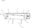
- Fig. 2 shows a side sectional view of the table 1 from Fig. 1 with the table leg 2 in a state before it is fully assembled.
- the first axis 9 is already inserted into the predetermined depth from the first side S1 and lies against the recess 6 without play on both sides.
- the second axis 10 is shown in a state in which it moves along the biasing surface 7 to generate a bias between the first axis 9 and the recess 6. Alternatively, clearance can be maintained or created therebetween.
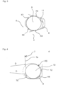
- Fig. 3 shows an enlarged detailed view of a detail A in Fig. 1 .
- the holding element 5 has an opening 11 for receiving the first axis 9.
- the opening 11 has a cross section that is designed to allow the first axis 9 to be inserted without force to enable.
- the opening 11 has a free cross section that is larger than a diameter of the first axis 9.
- the opening 11 has two contact points K1, K2.
- the opening 11 has an oval cross section, which is designed to enable the free cross section and the two contact points K1, K2.
- the opening 11 does not have an oval shape, but rather another suitable shape, for example an ellipse.
- the first axis 9 and the recess 6 have two contact points K3, K4. This ensures the play-free connection between the fastening element 4 and the holding element 5 on the first axis 9.
- Fig. 4 shows an enlarged detailed view of a detail B in Fig. 1 .
- the holding element 4 has an opening 12 for receiving the second axis 10.
- the opening 12 has a cross section that is designed to enable force-free insertion of the second axis 10.
- the opening 12 has a free cross section that is larger than a diameter of the second axis 10.
- the opening 12 has an oval cross section to enable the free cross section and the two contact points K5, K6.
- the opening 12 does not have an oval shape, but rather another suitable shape, for example an ellipse.
- Fig. 1 is a distance D between a central axis MA of the first axis 9 which lies against the recess 6 at the predetermined depth and without play on both sides and the biasing surface 7 shown, In Fig. 4 it is shown that the distance D along the course of the preload surface 7 from the second side S2 to the stop surface 8 is not constant.
- the biasing surface 7 has a first region 7a along which the distance D increases starting from the second side in order to bias the system by the movement of the second axis 10 along the biasing surface 7 or alternatively to eliminate play from the system. Furthermore, the biasing surface 7 has a second region 7b, along which the distance D from the first region 7a decreases. In an alternative embodiment, the distance D remains constant in the second region 7b.
- the distance between the central axis MA of the first axis 9, which rests against the recess 6 at the predetermined depth and without play on both sides, and the preload surface 7 can be constant, in which case freedom from play can be guaranteed without the system being affected by the movement of the second axis 10 to pretension or further pretension along the pretensioning surface 7.
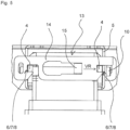
- Fig. 5 a sectional view of the table from Fig. 1 with a locking device 13 from the front.
- Fig. 5 is shown that the second axis 10 is arranged protruding between opposite sides of the holding element 5.
- the first axis 9 is also arranged projecting between the opposite sides of the holding element 5.
- the fastening element 5 has two recesses 6, each of which accommodates the first axis 9, and two biasing surfaces 7 and two stop surfaces 8, against which the second axis 10 then rests.
- first and second axles 9, 10 are only on one side of one side of the holding element 5 or on both sides of it Holding element 5 outwards, in which case only one recess 8 and only one preload surface 7 and stop surface 8 are provided.
- the locking device 13 is attached to the holding element 5 and has a latch 14 that is movable relative to the holding element 5. Furthermore, the locking device 13 has a biasing element 15 which pushes the bolt 14 in a locking direction VR into a locking position in which the locking device 13 locks the position of the second axis 10 resting on the stop surface 8.
- the fastening element 4 is in the state in which the first axis 9 rests on the recess 6 from the first side S1 at the predetermined depth and on both sides and the second axis 10 rests on the stop surface 8 and without play on the preload surface 7, fixed to the holding element 5.
- the locking device 13 is arranged on the holding element 5 such that the locking direction VR runs parallel to a direction of protrusion of the first and second axes 9, 10.
- the locking device 13 may not be provided with a biasing element and instead may be manually lockable; furthermore, it may not be attached to the holding element but to the fastening element and may also have a different locking direction. It is essential that the system is in the state in which the first axis 9 rests against the recess 6 from the first side S1 at the predetermined depth and on both sides and the second axis 10 rests against the stop surface 8 and against the preload surface 7 without play , is fixed.
- the first axis 9 of the holding element 5 is first inserted into the recess 6 of the fastening element 4, which is open towards the first side S1.
- the holding element 5 is moved so far that the first axis 9 rests on the recess 6 on both sides. This ensures that the second axis 10 is positioned so that it can move without collision with the second side S2 of the holding element 5 can move along the biasing surface 7 of the holding element 5.
- the second axis 10 rests on the second side S2 and the holding element 5 can be moved relative to the fastening element 4 so that the second axis 10 faces the biasing surface 7 arrived.
- a pivoting movement is then carried out between the fastening element 4 and the holding element 5, so that the second axis 10 of the holding element 5 moves along the biasing surface 7 of the fastening element 4 until the first axis 9 rests at the predetermined depth in the recess 6 and there is no play on both sides and the second axis rests on the stop surface 8 and without play on the preload surface 7.
- the fastening element is pivoted with respect to the holding element 5 or the holding element 5 is pivoted with respect to the fastening element 4.
- the second axis 10 initially moves in the first area 7a of the pretensioning surface 7, in which a distance between the central axis MA of the first axis 9, which lies against the recess 6 at the predetermined depth and without play on both sides, and the pretensioning surface 7 the course of the preload surface 7 from the second side S2 to the stop surface 8 is increased in order to generate a preload force between the axes 9, 10, the recess 6 and the preload surface 7.
- the second axis 10 then moves in the second region 7b of the pretensioning surface 7, in which the distance D decreases in order to maintain the position of the second axis 10 resting against the stop surface 8 in a positively guided manner. There will be a transition between the first and the second area if necessary detected tactilely.
- the system 3 is simply free of play due to the pivoting movement, without any preload force being generated.
Landscapes
- Furniture Connections (AREA)
- Connection Of Plates (AREA)
Description
- Die Erfindung betrifft ein System zum Befestigen eines Möbelbeins an einem Möbel und Verfahren zum Befestigen des Möbelbeins an dem Möbel, insbesondere ein System zum Befestigen eines Möbelbeins an einem Möbel und Verfahren zum Befestigen des Möbelbeins an dem Möbel, die eine einfache Montage ermöglichen.
- Möbel weisen in der Regel mehrere Komponenten auf. Ein Tisch beispielsweise besteht aus einem Rahmenelement, an dem auf der einen Seite eine Tischplatte und auf der anderen Seite Tisch- bzw. Möbelbeine befestigt sind.
- Wenn ein Kunde ein solches Möbel käuflich erwirbt, muss dieses vom Hersteller, vom Großhändler, oder vom Einzelhändler zum Kunden transportiert werden. Zum platzsparenden Transport wird das Möbel dabei in seine Einzelteilen zerlegt transportiert. Beim Endkunden müssen dann beispielsweise die einzelnen Möbelbeine ans Möbel montiert werden.
- Aus dem Stand der Technik sind Konstruktionen bekannt, durch welche ein Möbelbein an einem Möbel ohne Zuhilfenahme von Werkzeug angebracht werden kann, beispielsweise mittels einer Einrastvorrichtung. Allerdings haben solche Konstruktionen gemäß dem Stand der Technik den Nachteil, dass die so an einem Möbel angebrachten Möbelbeine nicht spielfrei befestigt sind. Daraus resultiert eine Schwingungsanfälligkeit des Möbels.
- Laut den "Anforderungen und Prüfungen von Büromöbeln - Leitfaden für die Sicherheitsanforderungen an Büro-Arbeitstische und Büroschränke in Deutschland" (siehe DIN-Fachbericht 147, Juni 2006, Punkt 3.6) des DIN-Instituts (Deutsches Institut für Normung e.V.) muss durch die Konstruktion eines Büro-Arbeitstisches allerdings sichergestellt sein, dass Schwingungen verhindert werden. Hierfür ist ein spezieller Test mittels eines Pendelschlaghammers vorgesehen. Konstruktionen gemäß dem Stand der Technik, welche das Befestigen eines Möbelbeins an einem Möbel ohne die Zuhilfenahme von Werkzeug vorsehen, erfüllen die Kriterien des DIN-Instituts bezüglich der Schwingungsfreiheit in der Regel nicht.
- Aus dem Stand der Technik-Dokument
DE 10 2005 037 394 A1 ist ein solches Standfußbefestigungssystem bekannt, in welchem ein Verriegelungsmechanismus zum werkzeuglosen Verriegeln eines Tischbeins an einem Tisch offenbart wird. Bei der offenbarten Konstruktion wird das Tischbein schräg in eine Ausnehmung des Tisches eingesetzt, und durch ein Kippen (bzw. Aufrichten) des Tischbeins ein Verriegeln durch ein Verriegelungselement ausgelöst. Bei dieser Konstruktion wird in der Regel keine spielfreie Festlegung des Tischbeins innerhalb der Ausnehmung erreicht werden, es sei denn, die Abmessungen der zu verriegelnden Teile, also Ausnehmung und Kopfstück, sind als Presspassung ausgeführt, was sehr aufwändig und extrem teuer in der Herstellung wäre. Zudem wäre die Montage nur mit extrem großen Kraftaufwand möglich, da man die Bauteile bei einer Presspassung mit hoher Kraft einpressen muss, damit sie sicher gehalten werden können. - Es ist daher Aufgabe der vorliegenden Erfindung, ein System zum Befestigen eines Möbelbeins an einem Möbel bereitzustellen, mit welchem ein Möbelbein schnell, einfach, kostengünstig und spielfrei, zudem ohne Zuhilfenahme von Werkzeug an einem Möbel befestigt werden kann.
- Die Aufgabe wird durch ein System gemäß Anspruch 1 und ein Verfahren gemäß Anspruch 12 gelöst. Vorteilhafte Weiterentwicklungen der Erfindung sind in den abhängigen Ansprüchen enthalten.
- Gemäß einem Aspekt der Erfindung weist ein System zum Befestigen eines Möbelbeins an einem Möbel ein Befestigungselement, das dazu eingerichtet ist, an dem Möbelbein befestigbar zu sein, und ein Halteelement, das dazu eingerichtet ist, an dem Möbel befestigbar zu sein, auf. Das Halteelement weist an einer Seite einen ersten Vorsprung und einen von dem ersten Vorsprung beabstandeten zweiten Vorsprung auf. Das Befestigungselement weist eine erste Seite, eine an der ersten Seite angrenzende zweite Seite und eine der ersten Seite gegenüberliegende dritte Seite auf. Ferner weist das Befestigungselement eine zur ersten Seite hin offene Aussparung, die dazu eingerichtet ist, den ersten Vorsprung aufzunehmen, eine von der zweiten Seite ausgehend an der dritten Seite entlang verlaufende Vorspannfläche und eine sich an die Vorspannfläche anschließende von der dritten Seite abstehende Anschlagfläche auf.
- Das Halteelement mit dem ersten Vorsprung und dem zweiten Vorsprung, und das Befestigungselement mit der Aussparung, der Vorspannfläche und der Anschlagfläche sind dazu eingerichtet, dass das System in einem Zustand, in dem der erste Vorsprung von der ersten Seite aus in einer vorbestimmten Tiefe und dabei beidseitig spielfrei an der Aussparung anliegt und der zweite Vorsprung spielfrei an der Vorspannfläche und an der Anschlagfläche anliegt, eine spielfreie Befestigung des Möbelbeins am Möbel ermöglicht.
- Durch eine solche Konfiguration des Systems ist es mit einfachen und kostengünstigen Mitteln möglich, das Möbelbein einfach und spielfrei an das Möbel zu montieren.
- In einer vorteilhaften Weiterbildung des Systems ist der erste Vorsprung durch eine erste Achse ausgebildet und der zweite Vorsprung ist durch eine zweite Achse ausgebildet, die jeweils von dem Halteelement vorstehen.
- Achsen sind einfach und kostengünstig zu beschaffen oder anzufertigen und zu lagern, so dass eine kostengünstige Herstellung unterstützt wird.
- Gemäß einer weiteren vorteilhaften Weiterbildung des Systems sind die erste Achse und die zweite Achse zwischen gegenüberliegenden Seiten von dem Halteelement vorstehend angeordnet, und das Befestigungselement weist zwei Aussparungen, die jeweils dazu eingerichtet sind, die erste Achse aufzunehmen, und zwei Vorspannflächen und zwei Anschlagflächen, an denen jeweils die zweite Achse anliegt, auf.
- Durch das Vorsehen der ersten und zweiten Achsen an gegenüberliegenden Seiten, wobei die Seiten voneinander abgewandt oder einander zugewandt sein können, wird eine Stabilität des Systems erhöht und eine Lage des Möbelbeins zu dem Möbel kann einfach festgelegt werden.
- einer weiteren vorteilhaften Weiterbildung des Systems weist das Halteelement Öffnungen zum Aufnehmen der Achsen auf, und zumindest eine der Öffnungen weist einen Querschnitt auf, der dazu eingerichtet ist, dass ein kraftfreies Einführen einer von der ersten und zweiten Achse in die zumindest eine Öffnung ermöglicht wird, und dass, in dem Zustand, in dem die erste Achse von der ersten Seite aus in der vorbestimmten Tiefe und dabei beidseitig spielfrei an der Aussparung anliegt und die zweite Achse spielfrei an der Vorspannfläche und an der Anschlagfläche anliegt, die zumindest eine von der ersten und zweiten Achse und die zumindest eine der Öffnungen zwei Kontaktpunkte aufweisen.
- Durch den Querschnitt, der das kraftfreie Einführen ermöglicht, also beispielsweise ein freier Querschnitt, der größer als ein Durchmesser der Achse ist, kann die Achse einfach und schnell an dem Halteelement montiert werden. In der Position, in der der erste Vorsprung von der ersten Seite aus in der vorbestimmten Tiefe und dabei beidseitig spielfrei an der Aussparung anliegt, und der zweite Vorsprung spielfrei an der Vorspannfläche und an der Anschlagfläche anliegt, also in der montierten Position, ist durch die zwei Kontaktpunkte eine absolut spielfreie und statisch bestimmte Fixierung möglich.
- Bei einer vorteilhaften Weiterbildung des Systems weist zumindest eine Öffnung einen ovalen Querschnitt auf.
- Ein ovaler Querschnitt für das Ermöglichen bzw. Bereitstellen der zwei Kontaktpunkte ist einfach und kostengünstig herzustellen.
- In einer nächsten vorteilhaften Weiterbildung des Systems ist das Befestigungselement dazu eingerichtet, dass ein Abstand zwischen einer Mittelachse der ersten Achse und der Vorspannfläche entlang dem Verlauf der Vorspannfläche von der zweiten Seite zu der Anschlagfläche nicht konstant ist, wobei die erste Achse in der vorbestimmten Tiefe und dabei beidseitig spielfrei an der Aussparung anliegt.
- Durch den nicht konstanten Abstand wird es ermöglicht, dass eine Spielfreiheit des Systems in der Position, in der die zweite Achse an der Anschlagfläche und spielfrei an der Vorspannfläche anliegt, einfach zu erreichen ist, oder dass in dieser eine Vorspannkraft zwischen den Vorsprüngen, der Aussparung und der Vorspannfläche einfach in einer gewünschten Weise erzeugt wird, indem der Abstand entsprechend im Voraus abgestimmt wird.
- Bei einer nächsten vorteilhaften Weiterbildung des Systems weist die Vorspannfläche einen ersten Bereich, entlang dem sich der Abstand von der zweiten Seite ausgehend vergrößert, und einen sich an den ersten Bereich anschließenden zweiten Bereich, entlang dem sich der Abstand von dem zweiten Bereich ausgehend verkleinert oder konstant bleibt, auf.
- Durch das Vorsehen dieser zwei Bereiche kann das Verhalten des Befestigungselements zu dem Halteelement während der Montage beeinflusst werden. Da sich der Abstand in dem ersten Bereich vergrößert, wird bei einer Bewegung der Achse entlang der Vorspannfläche entweder allmählich eine Spielfreiheit erzeugt oder die Vorspannkraft wird kontrolliert aufgebracht. In dem zweiten Bereich kann dann die Spielfreiheit oder die Vorspannkraft einfach erhalten bleiben, da keine Kraftkomponente so wirkt, dass die Verbindung gelöst wird.
- Darüber hinaus kann ein Übergang von dem ersten in den zweiten Bereich taktil durch einen Monteur erfasst werden, so dass ein Erreichen der endgültigen Position durch den Monteur spürbar erfassbar ist.
- In einer weiteren vorteilhaften Weiterbildung des Systems weist die Aussparung eine Abmessung in Richtung zu der zweiten Seite auf, die sich von der ersten Seite ausgehend zu der dritten Seite hin verkleinert.
- Eine solche Form der Aussparung ist einfach herzustellen und dabei kann durch eine Abstimmung mit dem Durchmesser der Achse die Position der ersten Achse in der sie von der ersten Seite aus in der vorbestimmten Tiefe und dabei beidseitig spielfrei an der Aussparung anliegt, einfach bestimmt werden.
- Gemäß einer anderen vorteilhaften Weiterbildung des Systems weist das System eine Verriegelungseinrichtung auf. Die Verriegelungseinrichtung fixiert das Befestigungselement zu dem Halteelement in dem Zustand, in dem der erste Vorsprung von der ersten Seite aus in einer vorbestimmten Tiefe und dabei beidseitig an der Aussparung anliegt und der zweite Vorsprung an der Anschlagfläche und spielfrei an der Vorspannfläche anliegt.
- Durch diese Verriegelungseinrichtung kann die Position, in der der zweite Vorsprung an der Anschlagfläche anliegt, gesichert werden, so dass die spielfreie Verbindung zwischen dem Halteelement und dem Befestigungselement beispielsweise auch bei einem Anheben des Tisches an der Tischplatte nicht gelöst wird.
- Bei einer weiteren vorteilhaften Weiterentwicklung des Systems ist die Verriegelungseinrichtung an dem Halteelement angebracht und weist einen relativ zu dem Halteelement bewegbaren Riegel und ein Vorspannelement, das eingerichtet ist, den Riegel in einer Verriegelungsrichtung in eine Verriegelungsposition zu drängen, in der die Verriegelungseinrichtung die an der Anschlagfläche anliegende Position des zweiten Vorsprungs verriegelt, auf.
- In einer vorteilhaften Weiterbildung eines solchen Systems ist die Verriegelungseinrichtung an dem Halteelement so angeordnet ist und so ausgebildet, dass die Verriegelungsrichtung parallel zu einer Richtung eines Vorstehens des ersten und zweiten Vorsprungs verläuft.
- Durch diese Anordnung besteht die Möglichkeit, die Verriegelung nachträglich ergonomisch wieder zu lösen.
- Gemäß einem anderen Aspekt der Erfindung weist ein Verfahren zum Befestigen eines Möbelbeins an einem Möbel die folgenden Schritte auf: Einbringen des ersten Vorsprungs des Halteelements in die zur ersten Seite hin offene Aussparung des Befestigungselements; Ausführen einer Schwenkbewegung zwischen dem Befestigungselement und dem Halteelement so, dass sich der zweite Vorsprung des Halteelements entlang der Vorspannfläche bewegt, so dass der erste Vorsprung in der vorbestimmten Tiefe in der Aussparung und beidseitig spielfrei anliegt und der zweite Vorsprung an der Anschlagfläche und spielfrei an der Vorspannfläche anliegt.
- Durch dieses Verfahren ist es mit einfachen und kostengünstigen Mitteln möglich, das Möbelbein einfach und spielfrei an das Möbel zu montieren.
- Gemäß einer vorteilhaften Weiterentwicklung des Verfahrens wird die Position, in der der zweite Vorsprung an der Anschlagfläche anliegt, verriegelt.
- Dadurch kann die Position, in der der zweite Vorsprung an der Anschlagfläche anliegt, gesichert werden, so dass die Verbindung zwischen dem Halteelement und dem Befestigungselement beispielsweise auch bei einem Anheben des Tisches an der Tischplatte nicht gelöst wird.
- In einer vorteilhaften Weiterentwicklung des Verfahrens wird der zweite Vorsprung zunächst in einen ersten Bereich der Vorspannfläche bewegt, in dem sich ein Abstand zwischen einer Mittelachse einer in der vorbestimmten Tiefe und dabei beidseitig spielfrei an der Aussparung anliegenden ersten Achse als den ersten Vorsprung und der Vorspannfläche entlang dem Verlauf der Vorspannfläche von der zweiten Seite zu der Anschlagfläche vergrößert. Dabei wird eine Vorspannkraft zwischen den Vorsprüngen, der Aussparung und der Vorspannfläche aufzubringen oder eine Spielfreiheit erzeugt. Dann bewegt sich der zweite Vorsprung in einem zweiten Bereich der Vorspannfläche, in dem sich der Abstand verkleinert oder konstant bleibt, um die an der Anschlagfläche anliegende Position des zweiten Vorsprungs selbsttätig zu erhalten.
- Durch diese Merkmale des Verfahrens kann das Verhalten des Befestigungselements zu dem Halteelement während der Montage beeinflusst werden. Da sich der Abstand in dem ersten Bereich vergrößert, wird bei einer Bewegung der Achse entlang der Vorspannfläche entweder die Vorspannkraft kontrolliert aufgebracht oder allmählich eine Spielfreiheit erzeugt. In dem zweiten Bereich kann dann die Spielfreiheit oder die Vorspannkraft einfach erhalten bleiben, da keine Kraftkomponente so wirkt, dass die Verbindung gelöst wird.
- In einer weiteren vorteilhaften Weiterentwicklung des Verfahrens ist ein Übergang zwischen dem ersten und den zweiten Bereich der Vorspannfläche taktil erfassbar.
- Durch den Übergang kann einem Monteur durch ein spür- und/oder auch hörbares Rasten zurückgemeldet werden, dass eine endgültige Montageposition, nämlich die Position, in der der zweite Vorsprung an der Anschlagfläche anliegt und die spielfreie Verbindung hergestellt ist, erreicht ist.
- Die Erfindung wird nachstehend unter Bezugnahme auf die beigefügten Zeichnungen erläutert.
- Insbesondere zeigt:
- Fig. 1
- eine seitliche Schnittdarstellung eines Tischs mit einem daran montierten Tischbein;
- Fig. 2
- eine seitliche Schnittdarstellung des Tischs von
Fig. 1 mit dem Tischbein in einem Zustand, bevor es vollständig montiert ist; - Fig. 3
- eine vergrößerte Detailansicht eines Details A in
Fig. 1 ; - Fig. 4
- eine vergrößerte Detailansicht eines Details B in
Fig. 1 ; und - Fig. 5
- eine Schnittansicht des Tischs von
Fig. 1 von vorne mit einer Verriegelungseinrichtung. -
Fig. 1 zeigt eine seitliche Schnittdarstellung eines Tischs 1 als Ausführungsbeispiel für ein Möbel mit einem daran montierten Tischbein 2 als ein Ausführungsbeispiel für ein Möbelbein. Der Tisch 1 weist ein System 3 auf, das wiederum ein Befestigungselement 4 und ein Halteelement 5 aufweist, um das Tischbein 2 an dem Tisch 1 zu befestigen. - Das Befestigungselement 4 ist an dem Tischbein 2 befestigt und weist eine erste Seite S1, eine an der ersten Seite S1 angrenzende zweite Seite S2 und eine der ersten Seite S1 gegenüberliegende Seite S3 auf.
- Ferner weist das Befestigungselement 4 eine zur ersten Seite S1 hin offene Aussparung 6 auf. Von der zweiten Seite S2 ausgehend ist eine an der dritten Seite S3 entlang verlaufende Vorspannfläche 7 vorgesehen. Ferner ist an dem Befestigungselement 4 eine sich an die Vorspannfläche 7 anschließende von der dritten Seite S3 abstehende Anschlagfläche 8 vorgesehen. Ein unteres Ende der Vorspannfläche 7 und die Anschlagfläche 8 sind in dieser Ausführungsform in einer Vertiefung bzw. Ausnehmung des Befestigungselements 4 vorgesehen. In einer alternativen Ausführungsform ist die Vertiefung nicht vorgesehen. Ein Vorsehen der Vorspannfläche 7 und der Anschlagfläche 8 an einer offenen dritten Seite S3 ist ebenfalls möglich.
- Das Halteelement 5 ist an dem Tisch 1 befestigt. Das Halteelement 5 weist an einer Seite eine erste Achse 9 und eine von der ersten Achse 9 beabstandete zweite Achse 10 auf, die von dem Halteelement 5 von der Seite vorstehen. Die erste Achse 9 und zweite Achse 10 sind parallel angeordnet. In einer alternativen Ausführungsform sind nicht Achsen vorgesehen, sondern ein erster und ein davon beabstandeter zweiter geeignet geformter Vorsprung sind stattdessen vorgesehen. In einer weiteren alternativen Ausführungsform sind die Achsen 9, 10 nicht parallel angeordnet, sondern in einer anderen geeigneten Stellung zueinander, in der eine Vorspannung oder Spielfreiheit auf das System aufgebracht werden kann, ausgerichtet.
- Die Aussparung 6 des Befestigungselements 4 ist dazu eingerichtet, die erste Achse 9 aufzunehmen. Die Aussparung 6 weist eine Abmessung in Richtung der zweiten Seite S2 auf, die sich von der ersten Seite S1 ausgehend zu der dritten Seite S3 hin verkleinert. Alternativ ist es nicht zwingend erforderlich, dass sich die Abmessung in Richtung der zweiten Seite 2 verkleinert je größer eine Tiefe in der Aussparung 6 ist. Eine gleichbleibende Abmessung in Richtung der zweiten Seite S2 ist ebenfalls möglich, sofern die Abmessung auf einen Durchmesser der ersten Achse 9 so abgestimmt ist, dass ein spielfreies Aufnehmen gewährleistet ist.
- In
Fig. 1 ist ein Zustand gezeigt, in dem die erste Achse 9 von der ersten Seite S1 aus in einer vorbestimmten Tiefe und dabei beidseitig spielfrei an der Aussparung 6 anliegt und die zweite Achse 10 an der Anschlagfläche 8 und spielfrei an der Vorspannfläche 7 anliegt. In diesem Zustand sind das Halteelement mit dem ersten Vorsprung und dem zweiten Vorsprung, und das Befestigungselement mit der Aussparung, der Vorspannfläche und der Anschlagfläche dazu eingerichtet, dass eine spielfreie Befestigung des Tischbeins 2 am Tisch 1 ermöglicht wird. -
Fig. 2 zeigt eine seitliche Schnittdarstellung des Tischs 1 vonFig. 1 mit dem Tischbein 2 in einem Zustand, bevor es vollständig montiert ist. - Die erste Achse 9 ist bereits von der ersten Seite S1 aus in die vorbestimmte Tiefe eingebracht und liegt dabei beidseitig spielfrei an der Aussparung 6 an. Die zweite Achse 10 ist in einem Zustand dargestellt, in dem sie sich entlang der Vorspannfläche 7 bewegt, um eine Vorspannung zwischen der ersten Achse 9 und der Aussparung 6 zu erzeugen. Alternativ kann eine Spielfreiheit dazwischen aufrechterhalten oder erzeugt werden.
-
Fig. 3 zeigt eine vergrößerte Detailansicht eines Details A inFig. 1 . Das Halteelement 5 weist eine Öffnung 11 zum Aufnehmen der ersten Achse 9 auf. Die Öffnung 11 weist einen Querschnitt auf, der eingerichtet ist, ein kraftfreies Einführen der ersten Achse 9 zu ermöglichen. Dazu weist die Öffnung 11 einen freien Querschnitt auf, der größer als ein Durchmesser der ersten Achse 9 ist. - In dem in
Fig. 1 gezeigten Zustand, in dem die erste Achse 9 von der ersten Seite S1 aus in der vorbestimmten Tiefe und dabei beidseitig spielfrei an der Aussparung anliegt, und die zweite Achse 10 spielfrei an der Vorspannfläche 7 und an der Anschlagfläche 8 anliegt, weisen die erste Achse 9 und die Öffnung 11 zwei Kontaktpunkte K1, K2 auf. Die Öffnung 11 weist einen ovalen Querschnitt auf, der dazu eingerichtet ist, den freien Querschnitt und die beiden Kontaktpunkte K1, K2 zu ermöglichen. In einer alternativen Ausführungsform weist die Öffnung 11 keine ovale Form, sondern eine andere geeignete Form, beispielsweise eine Ellipse, auf. - Gleichzeitig weisen die erste Achse 9 und die Aussparung 6 zwei Kontaktpunkte K3, K4 auf. Dadurch ist die spielfreie Verbindung zwischen dem Befestigungselement 4 und dem Halteelement 5 an der ersten Achse 9 gewährleistet.
-
Fig. 4 zeigt eine vergrößerte Detailansicht eines Details B inFig. 1 . Das Halteelement 4 weist eine Öffnung 12 zum Aufnehmen der zweiten Achse 10 auf. Die Öffnung 12 weist einen Querschnitt auf, der eingerichtet ist, ein kraftfreies Einführen der zweiten Achse 10 zu ermöglichen. Dazu weist die Öffnung 12 einen freien Querschnitt auf, der größer als ein Durchmesser der zweiten Achse 10 ist. - In dem in
Fig. 1 gezeigten Zustand, in dem die erste Achse 9 von der ersten Seite S1 aus in der vorbestimmten Tiefe und dabei beidseitig spielfrei an der Aussparung anliegt, und die zweite Achse 10 spielfrei an der Vorspannfläche 7 und an der Anschlagfläche 8 anliegt, weisen die zweite Achse 10 und die Öffnungen 12 zwei Kontaktpunkte K5, K6 auf. Die Öffnung 12 weist einen ovalen Querschnitt auf, um den freien Querschnitt und die beiden Kontaktpunkte K5, K6 zu ermöglichen. In einer alternativen Ausführungsform weist die Öffnung 12 keine ovale Form, sondern eine andere geeignete Form, beispielsweise eine Ellipse, auf. - In
Fig. 1 ist ein Abstand D zwischen einer Mittelachse MA der in der vorbestimmten Tiefe und dabei beidseitig spielfrei an der Aussparung 6 anliegenden ersten Achse 9 und der Vorspannfläche 7 gezeigt, InFig. 4 ist gezeigt, dass der Abstand D entlang dem Verlauf der Vorspannfläche 7 von der zweiten Seite S2 zu der Anschlagfläche 8 nicht konstant ist. - Insbesondere weist die Vorspannfläche 7 einen ersten Bereich 7a auf, entlang dem sich der Abstand D von der zweiten Seite ausgehend vergrößert, um das System durch die Bewegung der zweiten Achse 10 entlang der Vorspannfläche 7 vorzuspannen oder alternativ ein Spiel aus dem System zu eliminieren. Ferner weist die Vorspannfläche 7 einen zweiten Bereich 7b auf, entlang dem sich der Abstand D von dem ersten Bereich 7a ausgehend verkleinert. In einer alternativen Ausführungsform bleibt der Abstand D in dem zweiten Bereich 7b konstant.
- In einer alternativen Ausführungsform kann der Abstand zwischen der Mittelachse MA der in der vorbestimmten Tiefe und dabei beidseitig spielfrei an der Aussparung 6 anliegenden ersten Achse 9 und der Vorspannfläche 7 konstant sein, wobei dann eine Spielfreiheit gewährleistet sein kann, ohne das System durch die Bewegung der zweiten Achse 10 entlang der Vorspannfläche 7 vorzuspannen oder weiter vorzuspannen.
-
Fig. 5 eine Schnittansicht des Tischs vonFig. 1 mit einer Verriegelungseinrichtung 13 von vorne. - In
Fig. 5 ist dargestellt, dass die zweite Achse 10 zwischen gegenüberliegenden Seiten von dem Halteelement 5 vorstehend angeordnet ist. Obwohl nicht dargestellt, ist auch die erste Achse 9 zwischen den gegenüberliegenden Seiten von dem Halteelement 5 vorstehend angeordnet. - Das Befestigungselement 5 weist zwei Aussparungen 6 auf, die jeweils die erste Achse 9 aufnehmen und zwei Vorspannflächen 7 und zwei Anschlagflächen 8 auf, an denen dann jeweils die zweite Achse 10 anliegt.
- In einer alternativen Ausführungsform stehen die erste und zweite Achse 9, 10 lediglich einseitig von einer Seite des Halteelements 5 oder beidseitig von dem Haltelement 5 nach außen vor, wobei dann ggf. nur eine Aussparung 8 und jeweils nur eine Vorspannfläche 7 und Anschlagfläche 8 vorgesehen sind.
- Die Verriegelungseinrichtung 13 ist an dem Halteelement 5 angebracht und weist einen relativ zu dem Halteelement 5 bewegbaren Riegel 14 auf. Ferner weist die Verriegelungseinrichtung 13 ein Vorspannelement 15 auf, das den Riegel 14 in einer Verriegelungsrichtung VR in eine Verriegelungsposition drängt, in der die Verriegelungseinrichtung 13 die an der Anschlagfläche 8 anliegende Position der zweiten Achse 10 verriegelt.
- Dadurch wird das Befestigungselement 4 in dem Zustand, in dem die erste Achse 9 von der ersten Seite S1 aus in der vorbestimmten Tiefe und dabei beidseitig an der Aussparung 6 anliegt und die zweite Achse 10 an der Anschlagfläche 8 und spielfrei an der Vorspannfläche 7 anliegt, zu dem Halteelement 5 fixiert.
- Die Verriegelungseinrichtung 13 ist an dem Halteelement 5 so angeordnet, dass die Verriegelungsrichtung VR parallel zu einer Richtung des Vorstehens der ersten und zweiten Achse 9, 10 verläuft.
- In alternativen Ausführungsformen kann die Verriegelungseinrichtung 13 nicht mit einem Vorspannelement versehen sein und stattdessen manuell verriegelbar sein, weiterhin kann sie nicht an dem Halteelement, sondern an dem Befestigungselement angebracht sein und außerdem eine andere Verriegelungsrichtung aufweisen. Wesentlich ist, dass das System in dem Zustand, in dem die erste Achse 9 von der ersten Seite S1 aus in der vorbestimmten Tiefe und dabei beidseitig an der Aussparung 6 anliegt und die zweite Achse 10 an der Anschlagfläche 8 und spielfrei an der Vorspannfläche 7 anliegt, fixiert wird.
- Im Betrieb wird zum Befestigen des Tischbeins 2 zunächst die erste Achse 9 des Halteelements 5 in die zur ersten Seite S1 hin offene Aussparung 6 des Befestigungselements 4 eingebracht. Das Halteelement 5 wird dabei so weit bewegt, dass die erste Achse 9 beidseitig an der Aussparung 6 anliegt. Dadurch ist gewährleistet, dass die zweite Achse 10 so positioniert ist, dass sie sich ohne Kollision mit der zweiten Seite S2 des Halteelements 5 an der Vorspannfläche 7 des Halteelements 5 entlang bewegen kann. Andererseits liegt, wenn die erste Achse 9 nicht ausreichend tief in die Aussparung 6 eingebracht wurde, die zweite Achse 10 auf der zweiten Seite S2 auf und das Halteelement 5 kann relativ zu dem Befestigungselement 4 so bewegt werden, dass die zweite Achse 10 zu der Vorspannfläche 7 gelangt.
- Anschließend wird eine Schwenkbewegung zwischen dem Befestigungselement 4 und dem Halteelement 5 ausgeführt, so dass sich die zweite Achse 10 des Halteelements 5 entlang der Vorspannfläche 7 des Befestigungselements 4 bewegt bis die erste Achse 9 in der vorbestimmten Tiefe in der Aussparung 6 und dabei beidseitig spielfrei anliegt und die zweite Achse an der Anschlagfläche 8 und spielfrei an der Vorspannfläche 7 anliegt. In Abhängigkeit von der Montagestellung des Tischs 1 wird das Befestigungselement bezüglich des Halteelements 5 oder das Halteelement 5 bezüglich des Befestigungselements 4 geschwenkt.
- Beim Ausführen der Schwenkbewegung zwischen dem Befestigungselement 4 und dem Halteelement 5 in die Position, in der die zweite Achse 10 an der Anschlagfläche 8 anliegt, wird, sofern die Verriegelungseinrichtung 13 mit dem Vorspannelement 15 für eine automatische Verriegelung vorgesehen ist, das System 3 automatisch verriegelt.
- Bei der Schwenkbewegung bewegt sich die zweite Achse 10 zunächst in dem ersten Bereich 7a der Vorspannfläche 7, in dem sich ein Abstand zwischen der Mittelachse MA der in der vorbestimmten Tiefe und dabei beidseitig spielfrei an der Aussparung 6 anliegenden ersten Achse 9 und der Vorspannfläche 7 entlang dem Verlauf der Vorspannfläche 7 von der zweiten Seite S2 zu der Anschlagfläche 8 vergrößert, um eine Vorspannkraft zwischen den Achsen 9, 10, der Aussparung 6 und der Vorspannfläche 7 zu erzeugen. Anschließend bewegt sich die zweite Achse 10 dann in dem zweiten Bereich 7b der Vorspannfläche 7, in dem sich der Abstand D verkleinert, um die an der Anschlagfläche 8 anliegende Position der zweiten Achse 10 zwangsgeführt zu erhalten. Dabei wird ein Übergang zwischen dem ersten und dem zweiten Bereich gegebenenfalls taktil erfasst. Alternativ wird das System 3 durch die Schwenkbewegung lediglich spielfrei, ohne dass eine Vorspannkraft erzeugt wird.
- Alle in der Beschreibung, den nachfolgenden Ansprüchen und der Zeichnung dargestellten Merkmale können sowohl einzeln als auch in beliebiger Kombination miteinander erfindungswesentlich sein.
Claims (15)
- System (3) zum Befestigen eines Möbelbeins an einem Möbel, aufweisend:ein Befestigungselement (4), das dazu eingerichtet ist, an dem Möbelbein befestigbar zu sein, undein Halteelement (5), das dazu eingerichtet ist, an dem Möbel befestigbar zu sein,wobeidas Halteelement (5) an einer Seite einen ersten Vorsprung und einen von dem ersten Vorsprung beabstandeten zweiten Vorsprung aufweist,das Befestigungselement (4)eine erste Seite (S1), eine an der ersten Seite (S1) angrenzende zweite Seite (S2) und eine der ersten Seite (S1) gegenüberliegende dritte Seite (S3),eine zur ersten Seite (S1) hin offene Aussparung (6), die dazu eingerichtet ist, den ersten Vorsprung aufzunehmen und,eine von der zweiten Seite (S2) ausgehend an der dritten Seite (S3) entlang verlaufende Vorspannfläche (7) und eine sich an die Vorspannfläche (7) anschließende von der dritten Seite (S3) abstehende Anschlagfläche (8) aufweist,wobei das Halteelement (5) mit dem ersten Vorsprung und dem zweiten Vorsprung, und das Befestigungselement (4) mit der Aussparung (6), der Vorspannfläche (7) und der Anschlagfläche (8) dazu eingerichtet sind, dassdas System (3) in einem Zustand, in dem der erste Vorsprung von der ersten Seite (S1) aus in einer vorbestimmten Tiefe und dabei beidseitig an der Aussparung (6) anliegt und der zweite Vorsprung an der Anschlagfläche (8) und spielfrei an der Vorspannfläche (7) anliegt, eine spielfreie Befestigung des Möbelbeins am Möbel ermöglicht.
- System (3) gemäß Anspruch 1, wobei
der erste Vorsprung durch eine erste Achse (9) ausgebildet ist und der zweite Vorsprung durch eine zweite Achse (10) ausgebildet ist, die jeweils von dem Halteelement (5) vorstehen. - System (3) gemäß Anspruch 2, wobeidie erste Achse (9) und die zweite Achse (10) zwischen gegenüberliegenden Seiten von dem Halteelement (5) vorzustehend angeordnet sind, unddas Befestigungselement (4) zwei Aussparungen (6), die jeweils dazu eingerichtet sind, die erste Achse (9) aufzunehmen, undzwei Vorspannflächen (7) und zwei Anschlagflächen (8), an denen jeweils die zweite Achse (10) anliegt, aufweist.
- System (3) gemäß Anspruch 2 oder 3, wobeidas Halteelement (5) Öffnungen (11, 12) zum Aufnehmen der Achsen (9, 10) aufweist, undzumindest eine der Öffnungen (11, 12) einen Querschnitt aufweist, der eingerichtet dazu ist, dass ein kraftfreies Einführen einer von der ersten Achse (9) und zweiten Achse (10) in die zumindest eine Öffnung (11, 12) zu ermöglicht wird, und dass in dem Zustand, in dem die erste Achse (9) von der ersten Seite (S1) aus in der vorbestimmten Tiefe und dabei beidseitig spielfrei an der Aussparung (6) anliegt, und die zweite Achse (10) an der Anschlagfläche (8) und spielfrei an der Vorspannfläche (7) anliegt, die zumindest eine von der ersten Achse (9) und zweiten Achse (10) und die zumindest eine der Öffnungen (11, 12) zwei Kontaktpunkte aufzuweisen.
- System (3) gemäß Anspruch 4, wobei
zumindest eine Öffnung (11, 12) einen ovalen Querschnitt aufweist. - System (3) gemäß einem der Ansprüche 2 bis 5, wobei
das Befestigungselement (4) dazu eingerichtet ist, dass ein Abstand (D) zwischen einer Mittelachse (MA) der in der vorbestimmten Tiefe und dabei beidseitig spielfrei an der Aussparung (6) anliegenden ersten Achse (9) und der Vorspannfläche (7) entlang dem Verlauf der Vorspannfläche (7) von der zweiten Seite (S2) zu der Anschlagfläche (8) nicht konstant ist. - System (3) gemäß Anspruch 6, wobei
die Vorspannfläche (7) einen ersten Bereich (7a), entlang dem sich der Abstand (D) von der zweiten Seite (S2) ausgehend vergrößert, und einen sich an den ersten Bereich (7a) anschließenden zweiten Bereich (7a), entlang dem sich der Abstand (D) von dem ersten Bereich (7a) ausgehend verkleinert oder konstant bleibt, aufweist. - System (3) gemäß einem der vorangehenden Ansprüche, wobei
die Aussparung (6) eine Abmessung in Richtung zu der zweiten Seite (S2) aufweist, die sich von der ersten Seite (S1) ausgehend zu der dritten Seite (S3) hin verkleinert. - System (3) gemäß einem der vorangehenden Ansprüche, wobei
das System (3) eine Verriegelungseinrichtung (13) aufweist, die das Befestigungselement (4) in dem Zustand, in dem der erste Vorsprung von der ersten Seite (S1) aus in einer vorbestimmten Tiefe und dabei beidseitig an der Aussparung (6) anliegt und der zweite Vorsprung an der Anschlagfläche (8) und spielfrei an der Vorspannfläche (7) anliegt, zu dem Halteelement (5) fixiert. - System (3) gemäß Anspruch 9, wobeidie Verriegelungseinrichtung (13) an dem Halteelement (5) angebracht ist, undeinen relativ zu dem Halteelement (5) bewegbaren Riegel (14) und ein Vorspannelement (15), das eingerichtet ist, den Riegel (14) in einer Verriegelungsrichtung (VR) in eine Verriegelungsposition, in der die Verriegelungseinrichtung (13) die an der Anschlagfläche (8) anliegende Position des zweiten Vorsprungs verriegelt, zu drängen, aufweist.
- System (3) gemäß Anspruch 10, wobei
die Verriegelungseinrichtung (13) an dem Halteelement (5) so angeordnet ist und so ausgebildet ist, dass die Verriegelungsrichtung (VR) parallel zu einer Richtung eines Vorstehens des ersten und zweiten Vorsprungs verläuft. - Verfahren zum Befestigen eines Möbelbeins an einem Möbel mittels eines Systems (3) gemäß einem der vorangehenden Ansprüche mit den Schritten:Einbringen des ersten Vorsprungs des Halteelements (5) in die zur ersten Seite (S1) hin offene Aussparung (6) des Befestigungselements (4);Ausführen einer Schwenkbewegung zwischen dem Befestigungselement (4) und dem Halteelement (5) so, dass sich der zweite Vorsprung des Halteelements (5) entlang der Vorspannfläche (7) des Befestigungselements (4) bewegt, so dass der erste Vorsprung in der vorbestimmten Tiefe in der Aussparung (6) und dabei beidseitig spielfrei anliegt und der zweite Vorsprung an der Anschlagfläche (8) und spielfrei an der Vorspannfläche (7) anliegt.
- Verfahren gemäß Anspruch 12 mit dem zusätzlichen Schritt
Verriegeln der Position, in der der zweite Vorsprung an der Anschlagfläche (8) anliegt. - Verfahren gemäß Anspruch 12 oder 13, wobeisich der zweite Vorsprung zunächst in einem ersten Bereich (7a) der Vorspannfläche (7), in dem sich ein Abstand (D) zwischen einer Mittelachse (MA) einer in der vorbestimmten Tiefe und dabei beidseitig spielfrei an der Aussparung (6) anliegenden ersten Achse (9) als den ersten Vorsprung und der Vorspannfläche (7) entlang dem Verlauf der Vorspannfläche (7) von der zweiten Seite (S2) zu der Anschlagfläche (8) vergrößert, bewegt, um eine Vorspannkraft zwischen den Vorsprüngen, der Aussparung (6) und der Vorspannfläche (7) aufzubringen oder eine Spielfreiheit zu erzeugen, undsich der zweite Vorsprung dann in einem zweiten Bereich (7b) der Vorspannfläche (7), in dem sich der Abstand (D) verkleinert oder konstant bleibt, bewegt, um die an der Anschlagfläche (8) anliegende Position des zweiten Vorsprungs selbsttätig zu erhalten.
- Verfahren gemäß Anspruch 14, wobei
ein Übergang zwischen dem ersten Bereich (7a) und dem zweiten Bereich (7b) der Vorspannfläche (7) taktil erfassbar ist.
Applications Claiming Priority (1)
| Application Number | Priority Date | Filing Date | Title |
|---|---|---|---|
| PCT/EP2019/072392 WO2021032299A1 (de) | 2019-08-21 | 2019-08-21 | System zum befestigen eines möbelbeins an einem möbel und verfahren zum befestigen des möbelbeins an dem möbel |
Publications (2)
| Publication Number | Publication Date |
|---|---|
| EP3972448A1 EP3972448A1 (de) | 2022-03-30 |
| EP3972448B1 true EP3972448B1 (de) | 2023-10-04 |
Family
ID=67770482
Family Applications (1)
| Application Number | Title | Priority Date | Filing Date |
|---|---|---|---|
| EP19759329.6A Active EP3972448B1 (de) | 2019-08-21 | 2019-08-21 | System zum befestigen eines möbelbeins an einem möbel und verfahren zum befestigen des möbelbeins an dem möbel |
Country Status (4)
| Country | Link |
|---|---|
| US (1) | US20220273095A1 (de) |
| EP (1) | EP3972448B1 (de) |
| CN (1) | CN114258274B (de) |
| WO (1) | WO2021032299A1 (de) |
Families Citing this family (2)
| Publication number | Priority date | Publication date | Assignee | Title |
|---|---|---|---|---|
| WO2021041680A1 (en) | 2019-08-27 | 2021-03-04 | Ergotron, Inc. | Workstation including simplified leg attachment |
| DE102020211087A1 (de) * | 2020-09-02 | 2022-03-03 | Veyhl Gmbh | Tischgestell und Tisch |
Family Cites Families (15)
| Publication number | Priority date | Publication date | Assignee | Title |
|---|---|---|---|---|
| US2813576A (en) * | 1954-12-15 | 1957-11-19 | Mayer Nathan | Knock down furniture assembly |
| US3796169A (en) * | 1972-09-25 | 1974-03-12 | American Standard Inc | Tiltable table structure |
| US5174225A (en) * | 1990-09-05 | 1992-12-29 | Colby Metal, Inc. | Releasable and tiltable table top |
| US5121697A (en) * | 1991-07-25 | 1992-06-16 | Berco Industries | Flip top table |
| US5354027A (en) * | 1992-05-05 | 1994-10-11 | Falcon Products, Inc. | Flip top removable table system |
| FI89668C (fi) * | 1992-09-14 | 1993-11-10 | Hannu Peltonen | Arrangemang foer att faesta en bordsskiva vid bordets fotdel |
| DE19941749A1 (de) * | 1999-09-02 | 2001-03-08 | Schaerf Ag | Klemmverbinder für Schreibtischplatten |
| US20030167980A1 (en) * | 2002-03-05 | 2003-09-11 | Mass-Set Kabushiki Kaisha | Folding structure |
| US7350469B2 (en) * | 2004-04-27 | 2008-04-01 | Paul Koning | Folding leg latch assembly |
| DE102005037394A1 (de) * | 2005-08-08 | 2007-02-15 | Davis Furniture Industries Inc. | Standfußbefestigungssystem sowie Standfuß für Möbelstück |
| US8413594B2 (en) * | 2010-08-18 | 2013-04-09 | DSA International, Inc. | Folding leg latch assembly |
| US9265340B2 (en) * | 2013-10-28 | 2016-02-23 | Knoll, Inc. | Article of furniture and method of stacking the same |
| DE102016100753A1 (de) * | 2015-03-05 | 2016-09-08 | Hettich Franke Gmbh & Co. Kg | Möbel und Möbelbeschlag zur Verbindung von Möbelteilen |
| DE202016002581U1 (de) * | 2015-04-30 | 2016-05-09 | Kesseböhmer Produktions GmbH & Co. KG | System zum Befestigen eines Möbelbeins an einem Möbel |
| US10842258B2 (en) * | 2017-09-18 | 2020-11-24 | Fellowes, Inc. | Variable height platform system |
-
2019
- 2019-08-21 WO PCT/EP2019/072392 patent/WO2021032299A1/de not_active Ceased
- 2019-08-21 US US17/631,496 patent/US20220273095A1/en not_active Abandoned
- 2019-08-21 EP EP19759329.6A patent/EP3972448B1/de active Active
- 2019-08-21 CN CN201980099551.9A patent/CN114258274B/zh active Active
Also Published As
| Publication number | Publication date |
|---|---|
| EP3972448A1 (de) | 2022-03-30 |
| US20220273095A1 (en) | 2022-09-01 |
| CN114258274A (zh) | 2022-03-29 |
| WO2021032299A1 (de) | 2021-02-25 |
| CN114258274B (zh) | 2024-01-16 |
Similar Documents
| Publication | Publication Date | Title |
|---|---|---|
| EP0697267B1 (de) | Befestigungsvorrichtung für ein Werkzeug oder Werkstück | |
| EP1834871B1 (de) | Anordnung zur lösbaren Befestigung von Bauteilen an einer Decke oder Wand | |
| DE102015216821B4 (de) | Möbelrahmen zum Sichern einer klappbaren Möbelsäule | |
| DE19726674A1 (de) | Bremsscheibe | |
| DE3926063A1 (de) | Justierbare befestigungsvorrichtung | |
| DE202016002581U1 (de) | System zum Befestigen eines Möbelbeins an einem Möbel | |
| EP1188936B1 (de) | Verbindungsanordnung zum lösbaren Verbinden zweier Bauteile | |
| WO2017016844A1 (de) | Befestigungsanordnung, clipkörper und clip | |
| WO2021032299A1 (de) | System zum befestigen eines möbelbeins an einem möbel und verfahren zum befestigen des möbelbeins an dem möbel | |
| WO2008046467A1 (de) | Verriegelbare steckkupplung | |
| DE9011157U1 (de) | Befestigungsvorrichtung für Möbel | |
| DE102006053197B3 (de) | Kraftfahrzeugtürscharnier | |
| DE4023583C2 (de) | ||
| DE3626052C2 (de) | Verbindungselement für System-Teile mit Modul-Langlöcher | |
| EP3819645A1 (de) | Versteifungselement zum versteifen eines testkontaktorsystems, verwendung und verfahren zur montage eines testkontaktorsystems | |
| EP2260742A1 (de) | Möbelsystem | |
| EP3059117B1 (de) | Kopfstütze | |
| EP1813824A2 (de) | Verbindungsvorrichtung für Möbelplatten | |
| DE19812300A1 (de) | Tisch | |
| EP3819513B1 (de) | Geitlager, ausstattungsvorrichtung mit wenigstens einem gleitlager und ausstattungsvorrichtung mit wenigstens einem drehbaren aufgenommenen lager | |
| DE202005019612U1 (de) | Vorrichtung zur lösbaren Befestigung eines flachen Bauteils an einer Trägerstruktur | |
| EP1213495B1 (de) | Halte-Blattfeder-Anordnung und Verbindungsanordnung zum lösbaren Verbinden zweier Bauteile | |
| EP3812052B1 (de) | Hochdruckreiniger und verfahren zur montage eines hochdruckreinigers | |
| DE202019106357U1 (de) | Modularer Bausatz zum Aufbau von dreidimensionalen Strukturen für die Aufnahme von Werkstücken mit Verriegelungselement und Halte- und Verlagerungsmittel | |
| DE102012102029B4 (de) | Verbindungselement zum Verbinden einer Relingstrebe mit einem Schubkasten |
Legal Events
| Date | Code | Title | Description |
|---|---|---|---|
| STAA | Information on the status of an ep patent application or granted ep patent |
Free format text: STATUS: UNKNOWN |
|
| STAA | Information on the status of an ep patent application or granted ep patent |
Free format text: STATUS: THE INTERNATIONAL PUBLICATION HAS BEEN MADE |
|
| PUAI | Public reference made under article 153(3) epc to a published international application that has entered the european phase |
Free format text: ORIGINAL CODE: 0009012 |
|
| STAA | Information on the status of an ep patent application or granted ep patent |
Free format text: STATUS: REQUEST FOR EXAMINATION WAS MADE |
|
| 17P | Request for examination filed |
Effective date: 20211222 |
|
| AK | Designated contracting states |
Kind code of ref document: A1 Designated state(s): AL AT BE BG CH CY CZ DE DK EE ES FI FR GB GR HR HU IE IS IT LI LT LU LV MC MK MT NL NO PL PT RO RS SE SI SK SM TR |
|
| DAV | Request for validation of the european patent (deleted) | ||
| DAX | Request for extension of the european patent (deleted) | ||
| GRAP | Despatch of communication of intention to grant a patent |
Free format text: ORIGINAL CODE: EPIDOSNIGR1 |
|
| STAA | Information on the status of an ep patent application or granted ep patent |
Free format text: STATUS: GRANT OF PATENT IS INTENDED |
|
| INTG | Intention to grant announced |
Effective date: 20230616 |
|
| GRAS | Grant fee paid |
Free format text: ORIGINAL CODE: EPIDOSNIGR3 |
|
| GRAA | (expected) grant |
Free format text: ORIGINAL CODE: 0009210 |
|
| STAA | Information on the status of an ep patent application or granted ep patent |
Free format text: STATUS: THE PATENT HAS BEEN GRANTED |
|
| AK | Designated contracting states |
Kind code of ref document: B1 Designated state(s): AL AT BE BG CH CY CZ DE DK EE ES FI FR GB GR HR HU IE IS IT LI LT LU LV MC MK MT NL NO PL PT RO RS SE SI SK SM TR |
|
| REG | Reference to a national code |
Ref country code: GB Ref legal event code: FG4D Free format text: NOT ENGLISH |
|
| REG | Reference to a national code |
Ref country code: CH Ref legal event code: EP |
|
| REG | Reference to a national code |
Ref country code: IE Ref legal event code: FG4D Free format text: LANGUAGE OF EP DOCUMENT: GERMAN |
|
| REG | Reference to a national code |
Ref country code: DE Ref legal event code: R096 Ref document number: 502019009578 Country of ref document: DE |
|
| REG | Reference to a national code |
Ref country code: LT Ref legal event code: MG9D |
|
| REG | Reference to a national code |
Ref country code: NL Ref legal event code: MP Effective date: 20231004 |
|
| PG25 | Lapsed in a contracting state [announced via postgrant information from national office to epo] |
Ref country code: NL Free format text: LAPSE BECAUSE OF FAILURE TO SUBMIT A TRANSLATION OF THE DESCRIPTION OR TO PAY THE FEE WITHIN THE PRESCRIBED TIME-LIMIT Effective date: 20231004 |
|
| PG25 | Lapsed in a contracting state [announced via postgrant information from national office to epo] |
Ref country code: GR Free format text: LAPSE BECAUSE OF FAILURE TO SUBMIT A TRANSLATION OF THE DESCRIPTION OR TO PAY THE FEE WITHIN THE PRESCRIBED TIME-LIMIT Effective date: 20240105 |
|
| PG25 | Lapsed in a contracting state [announced via postgrant information from national office to epo] |
Ref country code: IS Free format text: LAPSE BECAUSE OF FAILURE TO SUBMIT A TRANSLATION OF THE DESCRIPTION OR TO PAY THE FEE WITHIN THE PRESCRIBED TIME-LIMIT Effective date: 20240204 |
|
| PG25 | Lapsed in a contracting state [announced via postgrant information from national office to epo] |
Ref country code: LT Free format text: LAPSE BECAUSE OF FAILURE TO SUBMIT A TRANSLATION OF THE DESCRIPTION OR TO PAY THE FEE WITHIN THE PRESCRIBED TIME-LIMIT Effective date: 20231004 |
|
| PG25 | Lapsed in a contracting state [announced via postgrant information from national office to epo] |
Ref country code: ES Free format text: LAPSE BECAUSE OF FAILURE TO SUBMIT A TRANSLATION OF THE DESCRIPTION OR TO PAY THE FEE WITHIN THE PRESCRIBED TIME-LIMIT Effective date: 20231004 |
|
| PG25 | Lapsed in a contracting state [announced via postgrant information from national office to epo] |
Ref country code: LT Free format text: LAPSE BECAUSE OF FAILURE TO SUBMIT A TRANSLATION OF THE DESCRIPTION OR TO PAY THE FEE WITHIN THE PRESCRIBED TIME-LIMIT Effective date: 20231004 Ref country code: IS Free format text: LAPSE BECAUSE OF FAILURE TO SUBMIT A TRANSLATION OF THE DESCRIPTION OR TO PAY THE FEE WITHIN THE PRESCRIBED TIME-LIMIT Effective date: 20240204 Ref country code: GR Free format text: LAPSE BECAUSE OF FAILURE TO SUBMIT A TRANSLATION OF THE DESCRIPTION OR TO PAY THE FEE WITHIN THE PRESCRIBED TIME-LIMIT Effective date: 20240105 Ref country code: ES Free format text: LAPSE BECAUSE OF FAILURE TO SUBMIT A TRANSLATION OF THE DESCRIPTION OR TO PAY THE FEE WITHIN THE PRESCRIBED TIME-LIMIT Effective date: 20231004 Ref country code: BG Free format text: LAPSE BECAUSE OF FAILURE TO SUBMIT A TRANSLATION OF THE DESCRIPTION OR TO PAY THE FEE WITHIN THE PRESCRIBED TIME-LIMIT Effective date: 20240104 Ref country code: PT Free format text: LAPSE BECAUSE OF FAILURE TO SUBMIT A TRANSLATION OF THE DESCRIPTION OR TO PAY THE FEE WITHIN THE PRESCRIBED TIME-LIMIT Effective date: 20240205 |
|
| PG25 | Lapsed in a contracting state [announced via postgrant information from national office to epo] |
Ref country code: SE Free format text: LAPSE BECAUSE OF FAILURE TO SUBMIT A TRANSLATION OF THE DESCRIPTION OR TO PAY THE FEE WITHIN THE PRESCRIBED TIME-LIMIT Effective date: 20231004 Ref country code: RS Free format text: LAPSE BECAUSE OF FAILURE TO SUBMIT A TRANSLATION OF THE DESCRIPTION OR TO PAY THE FEE WITHIN THE PRESCRIBED TIME-LIMIT Effective date: 20231004 Ref country code: PL Free format text: LAPSE BECAUSE OF FAILURE TO SUBMIT A TRANSLATION OF THE DESCRIPTION OR TO PAY THE FEE WITHIN THE PRESCRIBED TIME-LIMIT Effective date: 20231004 Ref country code: NO Free format text: LAPSE BECAUSE OF FAILURE TO SUBMIT A TRANSLATION OF THE DESCRIPTION OR TO PAY THE FEE WITHIN THE PRESCRIBED TIME-LIMIT Effective date: 20240104 Ref country code: LV Free format text: LAPSE BECAUSE OF FAILURE TO SUBMIT A TRANSLATION OF THE DESCRIPTION OR TO PAY THE FEE WITHIN THE PRESCRIBED TIME-LIMIT Effective date: 20231004 Ref country code: HR Free format text: LAPSE BECAUSE OF FAILURE TO SUBMIT A TRANSLATION OF THE DESCRIPTION OR TO PAY THE FEE WITHIN THE PRESCRIBED TIME-LIMIT Effective date: 20231004 |
|
| REG | Reference to a national code |
Ref country code: DE Ref legal event code: R097 Ref document number: 502019009578 Country of ref document: DE |
|
| PG25 | Lapsed in a contracting state [announced via postgrant information from national office to epo] |
Ref country code: DK Free format text: LAPSE BECAUSE OF FAILURE TO SUBMIT A TRANSLATION OF THE DESCRIPTION OR TO PAY THE FEE WITHIN THE PRESCRIBED TIME-LIMIT Effective date: 20231004 |
|
| PG25 | Lapsed in a contracting state [announced via postgrant information from national office to epo] |
Ref country code: CZ Free format text: LAPSE BECAUSE OF FAILURE TO SUBMIT A TRANSLATION OF THE DESCRIPTION OR TO PAY THE FEE WITHIN THE PRESCRIBED TIME-LIMIT Effective date: 20231004 |
|
| PG25 | Lapsed in a contracting state [announced via postgrant information from national office to epo] |
Ref country code: SK Free format text: LAPSE BECAUSE OF FAILURE TO SUBMIT A TRANSLATION OF THE DESCRIPTION OR TO PAY THE FEE WITHIN THE PRESCRIBED TIME-LIMIT Effective date: 20231004 |
|
| PG25 | Lapsed in a contracting state [announced via postgrant information from national office to epo] |
Ref country code: SM Free format text: LAPSE BECAUSE OF FAILURE TO SUBMIT A TRANSLATION OF THE DESCRIPTION OR TO PAY THE FEE WITHIN THE PRESCRIBED TIME-LIMIT Effective date: 20231004 Ref country code: SK Free format text: LAPSE BECAUSE OF FAILURE TO SUBMIT A TRANSLATION OF THE DESCRIPTION OR TO PAY THE FEE WITHIN THE PRESCRIBED TIME-LIMIT Effective date: 20231004 Ref country code: RO Free format text: LAPSE BECAUSE OF FAILURE TO SUBMIT A TRANSLATION OF THE DESCRIPTION OR TO PAY THE FEE WITHIN THE PRESCRIBED TIME-LIMIT Effective date: 20231004 Ref country code: IT Free format text: LAPSE BECAUSE OF FAILURE TO SUBMIT A TRANSLATION OF THE DESCRIPTION OR TO PAY THE FEE WITHIN THE PRESCRIBED TIME-LIMIT Effective date: 20231004 Ref country code: EE Free format text: LAPSE BECAUSE OF FAILURE TO SUBMIT A TRANSLATION OF THE DESCRIPTION OR TO PAY THE FEE WITHIN THE PRESCRIBED TIME-LIMIT Effective date: 20231004 Ref country code: DK Free format text: LAPSE BECAUSE OF FAILURE TO SUBMIT A TRANSLATION OF THE DESCRIPTION OR TO PAY THE FEE WITHIN THE PRESCRIBED TIME-LIMIT Effective date: 20231004 Ref country code: CZ Free format text: LAPSE BECAUSE OF FAILURE TO SUBMIT A TRANSLATION OF THE DESCRIPTION OR TO PAY THE FEE WITHIN THE PRESCRIBED TIME-LIMIT Effective date: 20231004 |
|
| PLBE | No opposition filed within time limit |
Free format text: ORIGINAL CODE: 0009261 |
|
| STAA | Information on the status of an ep patent application or granted ep patent |
Free format text: STATUS: NO OPPOSITION FILED WITHIN TIME LIMIT |
|
| 26N | No opposition filed |
Effective date: 20240705 |
|
| PGFP | Annual fee paid to national office [announced via postgrant information from national office to epo] |
Ref country code: AT Payment date: 20240823 Year of fee payment: 6 |
|
| PG25 | Lapsed in a contracting state [announced via postgrant information from national office to epo] |
Ref country code: SI Free format text: LAPSE BECAUSE OF FAILURE TO SUBMIT A TRANSLATION OF THE DESCRIPTION OR TO PAY THE FEE WITHIN THE PRESCRIBED TIME-LIMIT Effective date: 20231004 |
|
| PG25 | Lapsed in a contracting state [announced via postgrant information from national office to epo] |
Ref country code: SI Free format text: LAPSE BECAUSE OF FAILURE TO SUBMIT A TRANSLATION OF THE DESCRIPTION OR TO PAY THE FEE WITHIN THE PRESCRIBED TIME-LIMIT Effective date: 20231004 |
|
| PG25 | Lapsed in a contracting state [announced via postgrant information from national office to epo] |
Ref country code: LU Free format text: LAPSE BECAUSE OF NON-PAYMENT OF DUE FEES Effective date: 20240821 |
|
| GBPC | Gb: european patent ceased through non-payment of renewal fee |
Effective date: 20240821 |
|
| PG25 | Lapsed in a contracting state [announced via postgrant information from national office to epo] |
Ref country code: MC Free format text: LAPSE BECAUSE OF FAILURE TO SUBMIT A TRANSLATION OF THE DESCRIPTION OR TO PAY THE FEE WITHIN THE PRESCRIBED TIME-LIMIT Effective date: 20231004 |
|
| REG | Reference to a national code |
Ref country code: BE Ref legal event code: MM Effective date: 20240831 |
|
| PG25 | Lapsed in a contracting state [announced via postgrant information from national office to epo] |
Ref country code: GB Free format text: LAPSE BECAUSE OF NON-PAYMENT OF DUE FEES Effective date: 20240821 |
|
| PG25 | Lapsed in a contracting state [announced via postgrant information from national office to epo] |
Ref country code: BE Free format text: LAPSE BECAUSE OF NON-PAYMENT OF DUE FEES Effective date: 20240831 |
|
| PG25 | Lapsed in a contracting state [announced via postgrant information from national office to epo] |
Ref country code: FR Free format text: LAPSE BECAUSE OF NON-PAYMENT OF DUE FEES Effective date: 20240831 |
|
| PG25 | Lapsed in a contracting state [announced via postgrant information from national office to epo] |
Ref country code: IE Free format text: LAPSE BECAUSE OF NON-PAYMENT OF DUE FEES Effective date: 20240821 |
|
| PG25 | Lapsed in a contracting state [announced via postgrant information from national office to epo] |
Ref country code: FI Free format text: LAPSE BECAUSE OF FAILURE TO SUBMIT A TRANSLATION OF THE DESCRIPTION OR TO PAY THE FEE WITHIN THE PRESCRIBED TIME-LIMIT Effective date: 20231004 |
|
| PGFP | Annual fee paid to national office [announced via postgrant information from national office to epo] |
Ref country code: DE Payment date: 20250827 Year of fee payment: 7 |
|
| PGFP | Annual fee paid to national office [announced via postgrant information from national office to epo] |
Ref country code: CH Payment date: 20250901 Year of fee payment: 7 |
|
| PG25 | Lapsed in a contracting state [announced via postgrant information from national office to epo] |
Ref country code: CY Free format text: LAPSE BECAUSE OF FAILURE TO SUBMIT A TRANSLATION OF THE DESCRIPTION OR TO PAY THE FEE WITHIN THE PRESCRIBED TIME-LIMIT; INVALID AB INITIO Effective date: 20190821 |
|
| PG25 | Lapsed in a contracting state [announced via postgrant information from national office to epo] |
Ref country code: HU Free format text: LAPSE BECAUSE OF FAILURE TO SUBMIT A TRANSLATION OF THE DESCRIPTION OR TO PAY THE FEE WITHIN THE PRESCRIBED TIME-LIMIT; INVALID AB INITIO Effective date: 20190821 |
|
| PG25 | Lapsed in a contracting state [announced via postgrant information from national office to epo] |
Ref country code: AT Free format text: LAPSE BECAUSE OF NON-PAYMENT OF DUE FEES Effective date: 20250821 |
|
| REG | Reference to a national code |
Ref country code: AT Ref legal event code: MM01 Ref document number: 1616786 Country of ref document: AT Kind code of ref document: T Effective date: 20250821 |