EP3971658B1 - Wearable-vorrichtung - Google Patents
Wearable-vorrichtung Download PDFInfo
- Publication number
- EP3971658B1 EP3971658B1 EP19928409.2A EP19928409A EP3971658B1 EP 3971658 B1 EP3971658 B1 EP 3971658B1 EP 19928409 A EP19928409 A EP 19928409A EP 3971658 B1 EP3971658 B1 EP 3971658B1
- Authority
- EP
- European Patent Office
- Prior art keywords
- groove
- bracket
- wearable device
- lock
- return spring
- Prior art date
- Legal status (The legal status is an assumption and is not a legal conclusion. Google has not performed a legal analysis and makes no representation as to the accuracy of the status listed.)
- Active
Links
Images


Classifications
-
- G—PHYSICS
- G04—HOROLOGY
- G04G—ELECTRONIC TIME-PIECES
- G04G17/00—Structural details; Housings
-
- G—PHYSICS
- G04—HOROLOGY
- G04G—ELECTRONIC TIME-PIECES
- G04G17/00—Structural details; Housings
- G04G17/08—Housings
- G04G17/083—Watches distributed over several housings
-
- G—PHYSICS
- G06—COMPUTING OR CALCULATING; COUNTING
- G06F—ELECTRIC DIGITAL DATA PROCESSING
- G06F1/00—Details not covered by groups G06F3/00 - G06F13/00 and G06F21/00
- G06F1/16—Constructional details or arrangements
- G06F1/1613—Constructional details or arrangements for portable computers
- G06F1/1633—Constructional details or arrangements of portable computers not specific to the type of enclosures covered by groups G06F1/1615 - G06F1/1626
- G06F1/1637—Details related to the display arrangement, including those related to the mounting of the display in the housing
- G06F1/1652—Details related to the display arrangement, including those related to the mounting of the display in the housing the display being flexible, e.g. mimicking a sheet of paper, or rollable
-
- G—PHYSICS
- G09—EDUCATION; CRYPTOGRAPHY; DISPLAY; ADVERTISING; SEALS
- G09F—DISPLAYING; ADVERTISING; SIGNS; LABELS OR NAME-PLATES; SEALS
- G09F9/00—Indicating arrangements for variable information in which the information is built-up on a support by selection or combination of individual elements
- G09F9/30—Indicating arrangements for variable information in which the information is built-up on a support by selection or combination of individual elements in which the desired character or characters are formed by combining individual elements
- G09F9/301—Indicating arrangements for variable information in which the information is built-up on a support by selection or combination of individual elements in which the desired character or characters are formed by combining individual elements flexible foldable or roll-able electronic displays, e.g. thin LCD, OLED
-
- H—ELECTRICITY
- H04—ELECTRIC COMMUNICATION TECHNIQUE
- H04B—TRANSMISSION
- H04B1/00—Details of transmission systems, not covered by a single one of groups H04B3/00 - H04B13/00; Details of transmission systems not characterised by the medium used for transmission
- H04B1/38—Transceivers, i.e. devices in which transmitter and receiver form a structural unit and in which at least one part is used for functions of transmitting and receiving
- H04B1/3827—Portable transceivers
- H04B1/385—Transceivers carried on the body, e.g. in helmets
-
- H—ELECTRICITY
- H04—ELECTRIC COMMUNICATION TECHNIQUE
- H04M—TELEPHONIC COMMUNICATION
- H04M1/00—Substation equipment, e.g. for use by subscribers
- H04M1/02—Constructional features of telephone sets
- H04M1/0202—Portable telephone sets, e.g. cordless phones, mobile phones or bar type handsets
- H04M1/026—Details of the structure or mounting of specific components
-
- G—PHYSICS
- G04—HOROLOGY
- G04G—ELECTRONIC TIME-PIECES
- G04G17/00—Structural details; Housings
- G04G17/02—Component assemblies
- G04G17/04—Mounting of electronic components
- G04G17/045—Mounting of the display
-
- G—PHYSICS
- G04—HOROLOGY
- G04G—ELECTRONIC TIME-PIECES
- G04G17/00—Structural details; Housings
- G04G17/08—Housings
-
- G—PHYSICS
- G06—COMPUTING OR CALCULATING; COUNTING
- G06F—ELECTRIC DIGITAL DATA PROCESSING
- G06F1/00—Details not covered by groups G06F3/00 - G06F13/00 and G06F21/00
- G06F1/16—Constructional details or arrangements
- G06F1/1613—Constructional details or arrangements for portable computers
- G06F1/163—Wearable computers, e.g. on a belt
-
- H—ELECTRICITY
- H04—ELECTRIC COMMUNICATION TECHNIQUE
- H04M—TELEPHONIC COMMUNICATION
- H04M1/00—Substation equipment, e.g. for use by subscribers
- H04M1/02—Constructional features of telephone sets
- H04M1/0202—Portable telephone sets, e.g. cordless phones, mobile phones or bar type handsets
- H04M1/0206—Portable telephones comprising a plurality of mechanically joined movable body parts, e.g. hinged housings
- H04M1/0208—Portable telephones comprising a plurality of mechanically joined movable body parts, e.g. hinged housings characterized by the relative motions of the body parts
- H04M1/0214—Foldable telephones, i.e. with body parts pivoting to an open position around an axis parallel to the plane they define in closed position
-
- H—ELECTRICITY
- H04—ELECTRIC COMMUNICATION TECHNIQUE
- H04M—TELEPHONIC COMMUNICATION
- H04M1/00—Substation equipment, e.g. for use by subscribers
- H04M1/72—Mobile telephones; Cordless telephones, i.e. devices for establishing wireless links to base stations without route selection
- H04M1/724—User interfaces specially adapted for cordless or mobile telephones
- H04M1/72403—User interfaces specially adapted for cordless or mobile telephones with means for local support of applications that increase the functionality
- H04M1/72409—User interfaces specially adapted for cordless or mobile telephones with means for local support of applications that increase the functionality by interfacing with external accessories
- H04M1/724094—Interfacing with a device worn on the user's body to provide access to telephonic functionalities, e.g. accepting a call, reading or composing a message
- H04M1/724095—Worn on the wrist, hand or arm
Definitions
- the present application relates to the technical field of electric devices, and in particularly, to a wearable device.
- terminal devices such as wristbands and smart watches usually have wearability and display functions.
- Display areas of bracelets and smart watches mainly have two shapes: circular and square.
- the display area of the current smart watch is generally within 40 mm (1.6 inches), obviously its display area is small, and the display experience is poor.
- the circular display screen when the user is operating by hand, one finger occupies almost half of the display area. If the user needs to operate for a long time, the user needs to keep raising the wrist which wears the smart watch or cannot operate freely with single hand. The operation experience is restricted, and the experience effect is poor.
- the existing smart watches capable of communicating need to make a sound through a loudspeaker, so that audio content can be easily heard by others, thereby a problem of privacy is arised.
- the equipment includes a wearable part and a display part installed on the wearable part, and is characterized in that the display part includes a main body, a foldable frame, a first display screen and a second display screen, wherein the foldable frame is installed on the main body and comprises a first frame body and a second frame body which are movably connected with each other through a bending piece, the first frame body is fixed to the main body, and the second frame body covers the first frame body after being bent towards the first frame body along the bending piece and is positioned outside the main body after being bent in the direction away from the first frame body along the bending piece.
- the first display screen is a flexible screen and embedded in the foldable frame, and the part, embedded in the second frame body, of the first display screen moves along with the second frame body.
- One of the objectives of the embodiments of the present application is to provide a wearable device, which aims to solve the problems of the existing wearable device that the display area is small, the touch experience is poor, and the voice privacy protection is insufficient.
- a wearable device including: a wearable assembly and a display device which is detachably mounted on the wearable assembly, and the display device includes:
- the wearable device further includes a connecting means for realizing mutual folding of the first body and the second body, and the connecting end of the first body is rotatably connected to a connecting end of the second body through the connecting means, and the flexible display device is located outside the connecting means.
- an opening/closing angle between the first body and the second body is 0° to 180°.
- the connecting means includes one or more of a folding sheet and a folding tube that can be folded.
- the connecting means includes a rotating shaft.
- the rotating shaft is a damped rotating shaft.
- the flexible display device is fixed on the display device by waterproof double-sided tape or glue.
- the wearable device further includes a lock mechanism
- the wearable assembly includes:
- the bracket defines a groove for receiving the display device after being folded.
- two opposite ends of the bracket are respectively provided with one lock mechanism , and two ends of the lock mechanism are respectively located in the bracket and the second body.
- the lock button includes an abutment portion and an insertion portion that are connected in turn, and the bracket defines an abutment groove and an insertion groove that are communicated in turn.
- the insertion portion is inserted into the insertion groove to abut against an end of the lock buckle, and an end of the abutment portion abuts against a groove wall of the abutment groove to limit a moving position of the lock button when it is pressed.
- one end of the first return spring is inserted into the abutment portion, the other end of the first return spring abuts against the groove wall of the abutment groove, and a through hole is defined in the abutment portion, and a first connecting groove communicating with the abutment groove is defined in the bracket.
- the lock mechanism further includes a limiter that passes through the first connecting groove and the through hole in turn. Both ends of the limiter are respectively located in the first connecting groove, and a middle part of the limiter is located in the through hole. Two opposite sides of the middle part of the limiter abut against a wall of the through hole and both ends of the limiter abut against a groove wall of the first connecting groove to limit a rebounding position of the lock button.
- the limiter is a vertically positioned elastic sheet, and the elastic sheet is in an "S" shape.
- the lock buckle includes a connecting portion and a moving portion connected in turn, and an end of the connecting portion away from the moving portion is inserted into the insertion groove to abut against the insertion portion, the second body defines a second connecting groove and an receiving groove communicated in turn, and two ends of the second return spring are respectively connected with the connecting portion and a groove wall of the second connecting groove.
- both ends of the second return spring respectively abut against the connecting portion and the groove wall of the second connecting groove
- the lock mechanism further includes a non-enclosed clamping member.
- the clamping member is sleeved on an end of the moving portion away from the connecting portion.
- a card slot is defined at a position where the moving portion is connected to the clamping member, and the clamping member is clamped in the card slot.
- the beneficial effects of the wearable device provided by the present application are that, compared with the prior art, the connecting end of the first body and the second body are rotationally connected to achieve mutual rotation, so that the first body and the second body have folding or unfolding effect and drive the flexible display device to be folded or unfolded; moreover, the display device and the wearable assembly are detachably connected, and a detachable and foldable combination may maximize an improvement of the user experience.
- the wearable device can be taken out during use and used as a mobile phone, so that the wearable device may guarantee voice privacy, such as call privacy, and may be folded back after use for easier operation.
- the present invention provides a wearable device, which includes electronic devices such as a watch and a bracelet.
- the following embodiments all take a watch as an example.
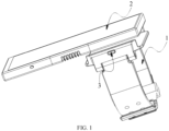
- the wearable device includes a wearable assembly 1 and a display device 2 detachably mounted on the wearable assembly 1, and the display device 2 includes a first body 211, a second body 212 and a flexible display device 22.
- the first body 211 has a connecting end, and the second body 212 is rotationally connected to a connecting end of the first body 211 to achieve rotation relative to each other.
- the second body 212 can be folded inwardly toward the first body 211 to overlap with the first body 211, and after the second body 212 is detached from the wearing component 1, the second body 212 can be folded outwards away from the first body 211 to be unfolded relative to each other.
- the flexible display device 22 is covered on the first body 211 and the second body 212, and can be folded inward or unfolded outward correspondingly with mutual rotation between the first body 211 and the second body 212.
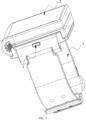
- the second body 212 can be folded inwardly toward the first body 211 to overlap with the first body 211, so that a part of the flexible display device 22 provided on the second body 212 moves with the second body 212, and then the flexible display device 22 is contracted to be equal to or smaller than a width of a wrist.
- a part of the flexible display device 22 provided on the first body 211 is used for display work, and there is no display on the part of the flexible display device 22 provided on the second body 212, and daily functions, such as viewing time, weather, and news may be satisfied.
- the covered display device 2 is detachably mounted on the wearable assembly 1, so that the display device 2 may be used as a watch.
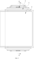
- the second body 212 detached from the wearable assembly 1 can be folded outward in a direction away from the first body 211 to be unfolded relative to each other, so that the entire flexible display device 22 is used for display, and the display device 2 being flattened is similar as a small mobile phone which may be convenient for users to use.
- the connecting end of the first body 211 and the second body 212 are rotationally connected to achieve mutual rotation relative to each other, so that the first body 211 and the second body 212 have folding or unfolding effect and drive the flexible display device 22 to be folded or unfolded.
- the display device 2 and the wearable assembly 1 are detachably connected, and detachable and foldable combination may maximize the improvement of the user experience.
- the wearable device can be taken out during use and can be used as a mobile phone, therefore the wearable device may guarantee voice privacy, such as call privacy, and may be folded back after use for easy operation.
- an opening/closing angle between the first body 211 and the second body 212 is 0° to 180°.
- the wearable device further includes a connecting means 213 for realizing mutual folding of the first body 211 and the second body 212, and the connecting end of the first body 211 is rotatably connected to a connecting end of the second body 212 through the connecting means 213, and the flexible display device 22 is located outside the connecting means 213, that is, the flexible display device 22 is located outside a whole constituted of the first body 211, the second body 212, and the connecting means 213.
- the connecting means 213 is folded to form an arc-shaped structure; when the opening/closing angle between the first body 211 and the second body 212 is 180°, that is, when the first body 211 and the second body 212 are placed side by side, the connecting means 213 is unfolded to form a "-"-shaped structure, so that the rotation of the connecting means may have a fixed rotation track and rotation radius, and the rotation of the flexible display device 22 may have a fixed rotation track and rotation radius.
- the connecting means 213 includes one or more of a folding sheet and a folding tube that can be folded. That is, the connecting means 213 may be a single folding sheet or a folding tube, and may also be a combination of a folding sheet and a folding tube.
- the folding tube is a folding piece that can be folded at a fixed point at any angle, which similar to a support rod of a desk lamp, and has a relatively simple structure.
- the connecting means 213 includes a rotating shaft, and the rotating shaft is a damped rotating shaft, so that the first body 211 or the second body 212 can be folded at a fixed point at any angle.
- the connecting means 213 with the above structure the first body 211 and the second body 212 can be stopped at any angle, and the user may choose a best experience effect through different unfolding angles.
- the connecting means 213 is made of a metal material or a plastic material, that is, the connecting means 213 includes a metal connecting means 213 or a plastic connecting means 213.
- the flexible display device 22 includes a flexible display screen and a flexible touch screen, so that the flexible display device 22 has display and touch functions. Where the flexible display device 22 is fixed on the display device 2 by waterproof double-sided tape or glue. Of course, only when the flexible display device 22 is a flexible display screen, it can be activated and controlled by voice, and unfolding is only for a larger display area and easy operation.
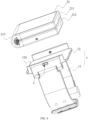
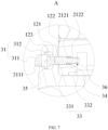
- the wearable device further includes a lock mechanism 3, and the wearable assembly 1 includes a watch band 11 and a bracket 12 connected to the watch band 11.
- the second body is detachably connected to the bracket 12 through the lock mechanism 3.
- the number of the lock mechanism 3 is at least one, and in specific applications, the number of the lock mechanism 3 is one, two or more.
- the bracket 12 defines a groove 124, and the groove 124 is used for receiving the display device 2 after being covered. Two opposite ends of the bracket 12 are respectively provided with one lock mechanism 3 detachably inserted into the end of the bracket 12, and two ends of the lock mechanism 3 are respectively located in the bracket 12 and the second body 212.
- the first body 211 is detachably connected to the bracket 12 through the lock mechanism 3, or one end of the lock mechanism 3 is located between the first body 211 and the second body 212, for example, grooves are provided on the first body 211 and the second body 212 respectively.
- the grooves on the first body 211 and the second body 212 form a connecting hole for receiving the lock mechanism 3, so that one end of the lock mechanism 3 can be inserted into the connecting hole.
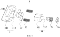
- the lock mechanism 3 includes: a lock button 31, a first return spring 32, a lock buckle 33, and a second return spring 34.
- One end of the lock button 31 is inserted into the bracket 12; two ends of the first return spring 32 are respectively connected to the lock button 31 and the bracket 12; both ends of the lock buckle 33 are respectively penetrated through the bracket 12 and the second body 212 and abut against an end of the lock button 31 passing through the bracket 12; and two ends of the second return spring 34 are respectively connected to the lock buckle 33 and the second body 212.
- the other end of the lock button 31 can extend out of the bracket 12, and it can also be located in the bracket 12.
- the lock button 31 squeezes the first return spring 32 during a squeezing process
- the lock buckle 33 squeezes the second return spring 34 during the squeezing process, so that the first return spring 32 and the second return spring 34 are respectively in a compressed state.
- the lock button 31 returns to an original position under the action of the first return spring 32, and the lock catch 33 returns to an original position under the action of the second return spring 34.
- the lock button 31 in order to prevent the lock button 31 from overly squeezing the first return spring 32 and causing the first return spring 32 to lose its resilience, the lock button 31 includes an abutment portion 311 and an insertion portion 312 that are connected in turn, and the bracket 12 defines an abutment groove 121 and an insertion groove 122 that are communicated in turn.
- the insertion portion 312 is inserted into the insertion groove 122 to abut against an end of the lock buckle 33, and an end of the abutment portion 311 abuts against a groove wall of the abutment groove 121 to limit a pressing position of the lock buckle 33.
- the abutment portion 311 When the abutment portion 311 is pressed, the abutment portion 311 drives the insertion portion 312 to move inward together, so that the insertion portion 312 squeezes the lock buckle 33. When the abutment portion 311 abuts against the groove wall of the abutment groove 121, the abutment portion 311 will no longer move inward.
- the lock mechanism 3 when one end of the first return spring 32 is inserted into the abutment portion 311, and the other end of the first return spring 32 abuts against the groove wall of the abutment groove 121, in order to avoid the lock button 31 being released from the bracket 12 under the action of the resilience of the first return spring 32, the lock mechanism 3 further includes a limiter 35.
- a through hole 3111 is defined in the abutment portion 311, and a first connecting groove 123 communicating with the abutment groove 121 is defined in the bracket 12.
- One end of the abutment portion 311 passes through the first connecting groove 123 and the abutment groove 121 in turn and abuts against the lock buckle 33.
- the limiter 35 passes through the first connecting groove 123 and the through hole 3111 in turn, a middle part of the limiter 35 is located in the through hole 3111. Both ends of the limiter 35 are respectively located in the first connecting groove 123, and two opposite sides of the limiter 35 are respectively abut against the through hole 3111 to limit a rebounding position of the lock button 31, thereby avoiding the lock button 31 being released from the bracket 12.
- the limiter 35 is a vertically positioned elastic sheet, the elastic sheet is in an "S" shape, a middle part of the elastic sheet is located in the through hole 3111 of the abutment portion 311, both ends of the elastic sheet are located in the connecting groove, and both sides of the elastic sheet abut against the through hole 3111.
- the limiter 35 is not required to limit a rebounding position of the lock button 31. Since the first return spring 32 is fixedly connected to the lock button 31 and the bracket 12, the first return spring 32 can pull the lock button 31 while rebounding.
- the lock buckle 33 includes a connecting portion 331 and a moving portion 332 connected in turn, and an end of the connecting portion 331 away from the moving portion 332 is inserted into the insertion groove 122 to abut against the insertion portion 312, the second body 212 defines a second connecting groove 2121 and an receiving groove 2122 communicated in turn, and two ends of the second return spring 34 are respectively abut against the connecting portion 331 and a groove wall of the second connecting groove 2121.
- the connecting portion 331 is located in the second connecting groove 2121, and when the button of the lock buckle 33 is pushed, the moving portion 332 is pushed to move in the receiving groove 2122.
- the lock mechanism 3 further includes a non-enclosed clamping member 36.
- the clamping member 36 is sleeved on an end of the moving portion 332 away from the connecting portion 331.
- a card slot is defined at a position where the moving portion 332 is connected to the clamping member 36, and the clamping member 36 is clamped in the card slot.
Landscapes
- Engineering & Computer Science (AREA)
- General Physics & Mathematics (AREA)
- Physics & Mathematics (AREA)
- Theoretical Computer Science (AREA)
- Computer Hardware Design (AREA)
- General Engineering & Computer Science (AREA)
- Human Computer Interaction (AREA)
- Signal Processing (AREA)
- Computer Networks & Wireless Communication (AREA)
- Casings For Electric Apparatus (AREA)
- Buckles (AREA)
- Telephone Set Structure (AREA)
- Devices For Indicating Variable Information By Combining Individual Elements (AREA)
Claims (13)
- Am Körper tragbare Vorrichtung, umfassend: eine am Körper tragbare Anordnung (1) und eine abnehmbar an der am Körper tragbaren Anordnung (1) angebrachte Anzeigevorrichtung (2), wobei die Anzeigevorrichtung Folgendes umfasst:einen ersten Körper (211), der ein Verbindungsende aufweist;einen zweiten Körper (212), der drehbar mit dem Verbindungsende des ersten Körpers (211) verbunden ist und nach innen in Richtung des ersten Körpers (211) geklappt werden kann, um den ersten Körper (211) zu überlagern, und wobei, nachdem der zweite Körper (212) von der am Körper tragbaren Anordnung (1) abgenommen ist, der zweite Körper (212) nach außen von dem ersten Körper (211) weg geklappt werden kann, damit sie relativ zueinander aufklappen; undeine biegsame Anzeigevorrichtung (22), die auf dem ersten Körper (211) und dem zweiten Körper (212) abgedeckt ist und mit gegenseitiger Drehung zwischen dem ersten Körper (211) und dem zweiten Körper (212) entsprechend nach innen geklappt oder nach außen aufgeklappt werden kann;dadurch gekennzeichnet, dass die am Körper tragbare Vorrichtung ferner einen Sicherungsmechanismus (3) umfasst, wobei:die am Körper tragbare Anordnung (1) Folgendes umfasst:ein Uhrarmband (11); undeine Halterung (12), die mit dem Uhrarmband (11) verbunden ist, wobei der zweite Körper (212) über den Sicherungsmechanismus (3) abnehmbar mit der Halterung (12) verbunden ist;wobei der Sicherungsmechanismus (3) Folgendes umfasst:eine Sicherungstaste (31), deren eines Ende in die Halterung (12) eingesteckt ist;einen Sicherungsriegel (33), dessen beide Enden jeweils in die Halterung (12) bzw. den zweiten Körper (212) eingesteckt sind und an dem durch die Halterung (12) ragenden einen Ende der Sicherungstaste (31) anliegen;eine erste Rückstellfeder (32), deren eines Ende mit einer dem Sicherungsriegel (33) zugewandten Seite der Sicherungstaste (31) verbunden ist und deren anderes Ende mit der Halterung (12) verbunden ist; undeine zweite Rückstellfeder (34), deren eines Ende mit dem Sicherungsriegel (33) verbunden ist und deren anderes Ende mit dem zweiten Körper (212) verbunden ist; wobei, wenn das andere Ende der Sicherungstaste (31) gedrückt wird, die Sicherungstaste (31) den Sicherungsriegel (33) drückt, um von der Halterung (12) getrennt zu werden, sodass sich die erste Rückstellfeder (32) und die zweite Rückstellfeder (34) jeweils in einem gestauchten Zustand befinden.
- Am Körper tragbare Vorrichtung nach Anspruch 1, wobei die am Körper tragbare Vorrichtung ferner ein Verbindungsmittel (213) zum Realisieren des gegenseitigen Klappens des erste Körpers (211) und des zweiten Körpers (212) umfasst und das Verbindungsende des ersten Körpers (211) über das Verbindungsmittel (213) drehbar mit einem Verbindungsende des zweiten Körpers (212) verbunden ist und sich die biegsame Anzeigevorrichtung (22) außerhalb des Verbindungsmittels (213) befindet.
- Am Körper tragbare Vorrichtung nach Anspruch 2, wobei ein Öffnungs-/Schließwinkel zwischen dem ersten Körper (211) und dem zweiten Körper (212) 0° bis 180° beträgt.
- Am Körper tragbare Vorrichtung nach Anspruch 2, wobei das Verbindungsmittel (213) eines oder mehrere von einem flachen Klappelement und einem Klappschlauch, das bzw. der umgeklappt werden kann, umfasst.
- Am Körper tragbare Vorrichtung nach Anspruch 2 wobei das Verbindungsmittel (213) eine sich drehende Achse umfasst; wobei die sich drehende Achse ein gedämpfte sich drehende Achse ist.
- Am Körper tragbare Vorrichtung nach Anspruch 1, wobei die Halterung (12) eine Nut (124) zum Aufnehmen der Anzeigevorrichtung, nachdem sie zugeklappt wurde, umfasst.
- Am Körper tragbare Vorrichtung nach Anspruch 6, wobei zwei gegenüberliegende Enden der Halterung (12) jeweils abnehmbar mit einem Sicherungsmechanismus (3) versehen sind und sich die zwei Enden des Sicherungsmechanismus jeweils in der Halterung (12) bzw. dem zweiten Körper (212) befinden.
- Am Körper tragbare Vorrichtung nach Anspruch 1, wobei die Sicherungstaste (31) einen Anlageabschnitt (311) und einen Einsteckabschnitt (312), die der Reihe nach verbunden sind, umfasst und die Halterung (12) eine Anlagenut (121) und eine Einstecknut (122) umfasst, die der Reihe nach miteinander in Verbindung stehen, wobei der Einsteckabschnitt (312) in die Einstecknut (122) eingesteckt ist, um an einem Ende des Sicherungsriegels (33) anzuliegen, und ein Ende des Anlageabschnitts (311) an einer Nutwand der Anlagenut (121) anliegt, um eine Bewegungsposition der Sicherungstaste (31) zu begrenzen, wenn sie gedrückt wird.
- Am Körper tragbare Vorrichtung nach Anspruch 8, wobei ein Ende der ersten Rückstellfeder (32) in den Anlageabschnitt (311) eingesteckt ist, das andere ende der ersten Rückstellfeder (32) an der Nutwand der Anlagenut (121) anliegt und ein Durchgangsloch (3111) in dem Anlageabschnitt (311) definiert ist und eine mit der Anlagenut (121) in Verbindung stehende erste Verbindungsnut (123) in der Halterung (12) definiert ist;
wobei der Sicherungsmechanismus (3) ferner einen Begrenzer (35) umfasst, der Begrenzer (35) der Reihe nach durch die erste Verbindungsnut (123) und das Durchgangsloch (3111) ragt und sich beide Enden des Begrenzers (35) in der ersten Verbindungsnut (123) befinden, wobei sich ein mittlerer Teil des Begrenzers (35) in dem Durchgangsloch (3111) befindet und zwei gegenüberliegende Seiten des mittleren Teils des Begrenzers (35) an einer Wand des Durchgangslochs (3111) anliegen, um eine Rückfederungsposition der Sicherungstaste (31) zu begrenzen. - Am Körper tragbare Vorrichtung nach Anspruch 9, wobei der Begrenzer (35) ein vertikal positioniertes elastisches flaches Element ist und das elastische flache Element eine "S"-Form aufweist.
- Am Körper tragbare Vorrichtung nach Anspruch 9, wobei der Sicherungsriegel (33) einen Verbindungsabschnitt (331) und einen beweglichen Abschnitt (332) umfasst, die der Reihe nach verbunden sind, und ein von dem beweglichen Abschnitt (332) abgelegenes Ende des Verbindungsabschnitts (331) in die Einstecknut (122) eingesteckt ist, um an dem Einsteckabschnitt (312) anzuliegen, wobei der zweite Körper (212) eine zweite Verbindungsnut (2121) und eine Aufnahmenut (2122) umfasst, die der Reihe nach in Verbindung stehen, und zwei Enden der zweiten Rückstellfeder (34) jeweils mit dem Verbindungsabschnitt (331) bzw. einer Nutwand der zweiten Verbindungsnut (2121) verbunden sind.
- Am Körper tragbare Vorrichtung nach Anspruch 11, wobei beide Enden der zweiten Rückstellfeder (34) jeweils an dem Verbindungsabschnitt (331) bzw. der Nutwand der zweiten Verbindungsnut (2121) anliegen und der Sicherungsmechanismus (3) ferner ein nicht eingeschlossenes Klemmelement (36) umfasst und das Klemmelement (36) auf ein von dem Verbindungsabschnitt (331) abgelegenes Ende des beweglichen Abschnitts (332) aufgesteckt ist.
- Am Körper tragbare Vorrichtung nach Anspruch 12, wobei ein Kartenschlitz an einer Position definiert ist, an der der bewegliche Abschnitt (332) mit dem Klemmelement (36) verbunden ist, und das Klemmelement (36) in dem Kartenschlitz geklemmt ist.
Applications Claiming Priority (2)
| Application Number | Priority Date | Filing Date | Title |
|---|---|---|---|
| CN201910396859.1A CN110032057B (zh) | 2019-05-14 | 2019-05-14 | 一种穿戴设备 |
| PCT/CN2019/118107 WO2020228286A1 (zh) | 2019-05-14 | 2019-11-13 | 一种穿戴设备 |
Publications (4)
| Publication Number | Publication Date |
|---|---|
| EP3971658A1 EP3971658A1 (de) | 2022-03-23 |
| EP3971658A4 EP3971658A4 (de) | 2023-02-22 |
| EP3971658B1 true EP3971658B1 (de) | 2025-05-07 |
| EP3971658C0 EP3971658C0 (de) | 2025-05-07 |
Family
ID=67241961
Family Applications (1)
| Application Number | Title | Priority Date | Filing Date |
|---|---|---|---|
| EP19928409.2A Active EP3971658B1 (de) | 2019-05-14 | 2019-11-13 | Wearable-vorrichtung |
Country Status (6)
| Country | Link |
|---|---|
| US (1) | US11971747B2 (de) |
| EP (1) | EP3971658B1 (de) |
| CN (1) | CN110032057B (de) |
| MY (1) | MY206179A (de) |
| SG (1) | SG11202109956PA (de) |
| WO (1) | WO2020228286A1 (de) |
Families Citing this family (9)
| Publication number | Priority date | Publication date | Assignee | Title |
|---|---|---|---|---|
| CN110032057B (zh) * | 2019-05-14 | 2024-12-24 | 广东小天才科技有限公司 | 一种穿戴设备 |
| CN110221534A (zh) * | 2019-06-28 | 2019-09-10 | 华勤通讯技术有限公司 | 电子手表 |
| US12314081B2 (en) * | 2019-09-24 | 2025-05-27 | Yoshiro Nakamats | Super smartphone |
| CN110824894A (zh) * | 2019-10-25 | 2020-02-21 | 武汉华星光电半导体显示技术有限公司 | 智能手表 |
| CN110784573B (zh) * | 2019-10-31 | 2021-02-05 | 武汉天马微电子有限公司 | 显示装置 |
| CN111022892B (zh) * | 2019-12-10 | 2021-12-21 | 广东海洋大学 | 一种用于教学的智能穿戴设备 |
| CN113726947B (zh) * | 2020-05-26 | 2022-09-09 | Oppo广东移动通信有限公司 | 语音通话方法、装置、终端及存储介质 |
| CN113917707A (zh) * | 2021-10-12 | 2022-01-11 | 歌尔光学科技有限公司 | 头戴设备 |
| EP4338636A1 (de) | 2022-09-15 | 2024-03-20 | EM Microelectronic-Marin SA | Wearable-vorrichtung |
Family Cites Families (28)
| Publication number | Priority date | Publication date | Assignee | Title |
|---|---|---|---|---|
| US20020021622A1 (en) * | 2000-04-07 | 2002-02-21 | Jean-Michel Baroche | Multifunction wristwatch with electronic device and foldable display screen |
| US8939333B2 (en) * | 2009-02-02 | 2015-01-27 | Óscar Sevilla Álvarez | Wrist holder for transporting and using electronic devices, with anti-electromagnetic radiation protection |
| US8328055B1 (en) * | 2010-01-19 | 2012-12-11 | Zenda Snyder | Wrist holder for a smartphone or personal digital assistant |
| US8662362B1 (en) * | 2013-07-24 | 2014-03-04 | James W. Bastian | Apparatus and method for supporting and operating an electronic device upon a user's forearm |
| WO2015056931A1 (ko) * | 2013-10-16 | 2015-04-23 | 이영이 | 손목시계형 플렉서블 디스플레이 장치 |
| US8936222B1 (en) * | 2013-11-27 | 2015-01-20 | James W. Bastian | System and method for magnetically supporting a device upon a structure |
| CN105814752A (zh) * | 2013-12-29 | 2016-07-27 | 苹果公司 | 电连接机构和机械连接机构 |
| US10362855B2 (en) * | 2013-12-31 | 2019-07-30 | Superior Communications, Inc. | Armband for mobile device |
| US12346156B2 (en) * | 2014-02-25 | 2025-07-01 | Medibotics Llc | Wrist-worn device with a variable-size display which is expanded by unrolling or sliding |
| US11429151B2 (en) * | 2014-02-25 | 2022-08-30 | Medibotics Llc | Wearable devices for the wrist and/or arm with multiple and multi-configuration displays |
| KR101480675B1 (ko) * | 2014-03-24 | 2015-01-14 | 김중영 | 손목 시계형 스마트 단말기 |
| US9471102B2 (en) * | 2014-08-28 | 2016-10-18 | Pebble Technology, Corp. | Connection by securing device with integrated circuitry layer |
| CN105376969A (zh) * | 2014-08-29 | 2016-03-02 | 康准电子科技(昆山)有限公司 | 手腕带 |
| US9929765B2 (en) * | 2015-03-17 | 2018-03-27 | Whelan & Williams Industries Inc. | Rotatable wrist mounted mobile device case |
| CN204838303U (zh) * | 2015-08-12 | 2015-12-09 | 深圳市埃微信息技术有限公司 | 智能手环壳体与表带按键型分离结构 |
| CN205103554U (zh) * | 2015-09-23 | 2016-03-23 | 广东小天才科技有限公司 | 一种智能手表 |
| CN105137743B (zh) | 2015-10-15 | 2018-05-15 | 京东方科技集团股份有限公司 | 一种智能手表 |
| JP6850587B2 (ja) * | 2015-11-18 | 2021-03-31 | 株式会社半導体エネルギー研究所 | 電子機器 |
| CN105867099A (zh) * | 2016-06-12 | 2016-08-17 | 北京大学深圳医院 | 老人监护用电话手表 |
| KR20180006721A (ko) * | 2016-07-11 | 2018-01-19 | 명준희 | 손목시계형 디스플레이 장치 |
| CN107232700A (zh) * | 2017-06-12 | 2017-10-10 | 捷开通讯(深圳)有限公司 | 一种智能穿戴设备 |
| CN107390504B (zh) | 2017-09-06 | 2020-05-05 | 武汉华星光电半导体显示技术有限公司 | 一种智能手表 |
| CN108021191A (zh) * | 2018-01-04 | 2018-05-11 | 广东小天才科技有限公司 | 一种可穿戴设备 |
| US10568410B2 (en) * | 2018-06-21 | 2020-02-25 | Grip Curl, LLC | Methods and apparatus for a gripping device for a portable computing device |
| CN208523936U (zh) * | 2018-06-28 | 2019-02-22 | 维沃移动通信有限公司 | 一种穿戴设备 |
| CN109372842B (zh) * | 2018-12-20 | 2024-07-09 | 歌尔科技有限公司 | 一种可穿戴设备连接结构及可穿戴设备 |
| CN209690725U (zh) * | 2019-05-14 | 2019-11-26 | 广东小天才科技有限公司 | 一种穿戴设备 |
| CN110032057B (zh) * | 2019-05-14 | 2024-12-24 | 广东小天才科技有限公司 | 一种穿戴设备 |
-
2019
- 2019-05-14 CN CN201910396859.1A patent/CN110032057B/zh active Active
- 2019-11-13 WO PCT/CN2019/118107 patent/WO2020228286A1/zh not_active Ceased
- 2019-11-13 SG SG11202109956P patent/SG11202109956PA/en unknown
- 2019-11-13 EP EP19928409.2A patent/EP3971658B1/de active Active
- 2019-11-13 MY MYPI2021005269A patent/MY206179A/en unknown
-
2021
- 2021-09-09 US US17/470,999 patent/US11971747B2/en active Active
Also Published As
| Publication number | Publication date |
|---|---|
| SG11202109956PA (en) | 2021-10-28 |
| CN110032057B (zh) | 2024-12-24 |
| MY206179A (en) | 2024-12-03 |
| EP3971658C0 (de) | 2025-05-07 |
| US20210405592A1 (en) | 2021-12-30 |
| EP3971658A1 (de) | 2022-03-23 |
| US11971747B2 (en) | 2024-04-30 |
| EP3971658A4 (de) | 2023-02-22 |
| WO2020228286A1 (zh) | 2020-11-19 |
| CN110032057A (zh) | 2019-07-19 |
Similar Documents
| Publication | Publication Date | Title |
|---|---|---|
| EP3971658B1 (de) | Wearable-vorrichtung | |
| EP4276320A1 (de) | Klappmechanismus und elektronische vorrichtung | |
| CN215120913U (zh) | 一种折叠屏手机保护壳 | |
| US10091897B2 (en) | Electronic devices with clips | |
| JP6752366B2 (ja) | サポートアセンブリ、文字盤とスマートブレスレット | |
| CN107979979B (zh) | 智能手环 | |
| US5363089A (en) | Electronic device having multi-position hinged mechanism | |
| WO2021238958A1 (zh) | 电子设备 | |
| JP6407403B2 (ja) | コンバーチブルスマートウォッチ | |
| US20190230803A1 (en) | Reel assembly, display device and smart bracelet | |
| EP3537236A1 (de) | Rahmenanordnung, zifferblatt und intelligentes armband | |
| WO2016101123A1 (zh) | 柔性屏扩展结构、柔性屏组件及终端 | |
| CN109171193B (zh) | 会议桌 | |
| EP3537254A1 (de) | Auslösevorrichtung, zifferblatt und intelligentes armband | |
| CN110708407B (zh) | 移动终端 | |
| CN101945153A (zh) | 一种折叠式手机 | |
| KR20120129234A (ko) | 힌지장치 및 이를 구비한 휴대용 전자장치 | |
| CN209690725U (zh) | 一种穿戴设备 | |
| CN110933210A (zh) | 电子设备 | |
| CN109873883A (zh) | 一种可折叠屏幕的手机 | |
| WO2018058472A1 (zh) | 智能手环 | |
| CN111090232A (zh) | 电子设备 | |
| CN206741225U (zh) | 智能手表 | |
| CN202005377U (zh) | 具有支架功能的新型背夹 | |
| KR20100130036A (ko) | 휴대 단말기용 자동 힌지장치 |
Legal Events
| Date | Code | Title | Description |
|---|---|---|---|
| STAA | Information on the status of an ep patent application or granted ep patent |
Free format text: STATUS: THE INTERNATIONAL PUBLICATION HAS BEEN MADE |
|
| PUAI | Public reference made under article 153(3) epc to a published international application that has entered the european phase |
Free format text: ORIGINAL CODE: 0009012 |
|
| STAA | Information on the status of an ep patent application or granted ep patent |
Free format text: STATUS: REQUEST FOR EXAMINATION WAS MADE |
|
| 17P | Request for examination filed |
Effective date: 20210914 |
|
| AK | Designated contracting states |
Kind code of ref document: A1 Designated state(s): AL AT BE BG CH CY CZ DE DK EE ES FI FR GB GR HR HU IE IS IT LI LT LU LV MC MK MT NL NO PL PT RO RS SE SI SK SM TR |
|
| DAV | Request for validation of the european patent (deleted) | ||
| DAX | Request for extension of the european patent (deleted) | ||
| A4 | Supplementary search report drawn up and despatched |
Effective date: 20230119 |
|
| RIC1 | Information provided on ipc code assigned before grant |
Ipc: H04M 1/02 20060101ALI20230113BHEP Ipc: G09F 9/30 20060101ALI20230113BHEP Ipc: G04G 17/08 20060101ALI20230113BHEP Ipc: G04G 17/04 20060101AFI20230113BHEP |
|
| GRAP | Despatch of communication of intention to grant a patent |
Free format text: ORIGINAL CODE: EPIDOSNIGR1 |
|
| STAA | Information on the status of an ep patent application or granted ep patent |
Free format text: STATUS: GRANT OF PATENT IS INTENDED |
|
| INTG | Intention to grant announced |
Effective date: 20241209 |
|
| GRAS | Grant fee paid |
Free format text: ORIGINAL CODE: EPIDOSNIGR3 |
|
| GRAA | (expected) grant |
Free format text: ORIGINAL CODE: 0009210 |
|
| STAA | Information on the status of an ep patent application or granted ep patent |
Free format text: STATUS: THE PATENT HAS BEEN GRANTED |
|
| AK | Designated contracting states |
Kind code of ref document: B1 Designated state(s): AL AT BE BG CH CY CZ DE DK EE ES FI FR GB GR HR HU IE IS IT LI LT LU LV MC MK MT NL NO PL PT RO RS SE SI SK SM TR |
|
| REG | Reference to a national code |
Ref country code: GB Ref legal event code: FG4D |
|
| REG | Reference to a national code |
Ref country code: CH Ref legal event code: EP |
|
| REG | Reference to a national code |
Ref country code: DE Ref legal event code: R096 Ref document number: 602019069819 Country of ref document: DE |
|
| REG | Reference to a national code |
Ref country code: IE Ref legal event code: FG4D |
|
| U01 | Request for unitary effect filed |
Effective date: 20250528 |
|
| U07 | Unitary effect registered |
Designated state(s): AT BE BG DE DK EE FI FR IT LT LU LV MT NL PT RO SE SI Effective date: 20250606 |
|
| PG25 | Lapsed in a contracting state [announced via postgrant information from national office to epo] |
Ref country code: ES Free format text: LAPSE BECAUSE OF FAILURE TO SUBMIT A TRANSLATION OF THE DESCRIPTION OR TO PAY THE FEE WITHIN THE PRESCRIBED TIME-LIMIT Effective date: 20250507 |
|
| PG25 | Lapsed in a contracting state [announced via postgrant information from national office to epo] |
Ref country code: NO Free format text: LAPSE BECAUSE OF FAILURE TO SUBMIT A TRANSLATION OF THE DESCRIPTION OR TO PAY THE FEE WITHIN THE PRESCRIBED TIME-LIMIT Effective date: 20250807 Ref country code: GR Free format text: LAPSE BECAUSE OF FAILURE TO SUBMIT A TRANSLATION OF THE DESCRIPTION OR TO PAY THE FEE WITHIN THE PRESCRIBED TIME-LIMIT Effective date: 20250808 |
|
| PG25 | Lapsed in a contracting state [announced via postgrant information from national office to epo] |
Ref country code: PL Free format text: LAPSE BECAUSE OF FAILURE TO SUBMIT A TRANSLATION OF THE DESCRIPTION OR TO PAY THE FEE WITHIN THE PRESCRIBED TIME-LIMIT Effective date: 20250507 |
|
| PG25 | Lapsed in a contracting state [announced via postgrant information from national office to epo] |
Ref country code: HR Free format text: LAPSE BECAUSE OF FAILURE TO SUBMIT A TRANSLATION OF THE DESCRIPTION OR TO PAY THE FEE WITHIN THE PRESCRIBED TIME-LIMIT Effective date: 20250507 |
|
| PG25 | Lapsed in a contracting state [announced via postgrant information from national office to epo] |
Ref country code: RS Free format text: LAPSE BECAUSE OF FAILURE TO SUBMIT A TRANSLATION OF THE DESCRIPTION OR TO PAY THE FEE WITHIN THE PRESCRIBED TIME-LIMIT Effective date: 20250807 |
|
| PG25 | Lapsed in a contracting state [announced via postgrant information from national office to epo] |
Ref country code: IS Free format text: LAPSE BECAUSE OF FAILURE TO SUBMIT A TRANSLATION OF THE DESCRIPTION OR TO PAY THE FEE WITHIN THE PRESCRIBED TIME-LIMIT Effective date: 20250907 |
|
| U20 | Renewal fee for the european patent with unitary effect paid |
Year of fee payment: 7 Effective date: 20251028 |