EP3971545B1 - Detektor für taktile kraft, detektionsvorrichtung für taktile kraft und roboterarm - Google Patents
Detektor für taktile kraft, detektionsvorrichtung für taktile kraft und roboterarm Download PDFInfo
- Publication number
- EP3971545B1 EP3971545B1 EP20805501.2A EP20805501A EP3971545B1 EP 3971545 B1 EP3971545 B1 EP 3971545B1 EP 20805501 A EP20805501 A EP 20805501A EP 3971545 B1 EP3971545 B1 EP 3971545B1
- Authority
- EP
- European Patent Office
- Prior art keywords
- load
- electrode plate
- sensor
- capacitance
- basis
- Prior art date
- Legal status (The legal status is an assumption and is not a legal conclusion. Google has not performed a legal analysis and makes no representation as to the accuracy of the status listed.)
- Active
Links
Images








Classifications
-
- G—PHYSICS
- G01—MEASURING; TESTING
- G01L—MEASURING FORCE, STRESS, TORQUE, WORK, MECHANICAL POWER, MECHANICAL EFFICIENCY, OR FLUID PRESSURE
- G01L1/00—Measuring force or stress, in general
- G01L1/14—Measuring force or stress, in general by measuring variations in capacitance or inductance of electrical elements, e.g. by measuring variations of frequency of electrical oscillators
- G01L1/142—Measuring force or stress, in general by measuring variations in capacitance or inductance of electrical elements, e.g. by measuring variations of frequency of electrical oscillators using capacitors
- G01L1/146—Measuring force or stress, in general by measuring variations in capacitance or inductance of electrical elements, e.g. by measuring variations of frequency of electrical oscillators using capacitors for measuring force distributions, e.g. using force arrays
-
- B—PERFORMING OPERATIONS; TRANSPORTING
- B25—HAND TOOLS; PORTABLE POWER-DRIVEN TOOLS; MANIPULATORS
- B25J—MANIPULATORS; CHAMBERS PROVIDED WITH MANIPULATION DEVICES
- B25J13/00—Controls for manipulators
- B25J13/08—Controls for manipulators by means of sensing devices, e.g. viewing or touching devices
- B25J13/081—Touching devices, e.g. pressure-sensitive
- B25J13/082—Grasping-force detectors
-
- B—PERFORMING OPERATIONS; TRANSPORTING
- B25—HAND TOOLS; PORTABLE POWER-DRIVEN TOOLS; MANIPULATORS
- B25J—MANIPULATORS; CHAMBERS PROVIDED WITH MANIPULATION DEVICES
- B25J15/00—Gripping heads and other end effectors
- B25J15/08—Gripping heads and other end effectors having finger members
-
- G—PHYSICS
- G01—MEASURING; TESTING
- G01L—MEASURING FORCE, STRESS, TORQUE, WORK, MECHANICAL POWER, MECHANICAL EFFICIENCY, OR FLUID PRESSURE
- G01L5/00—Apparatus for, or methods of, measuring force, work, mechanical power, or torque, specially adapted for specific purposes
- G01L5/22—Apparatus for, or methods of, measuring force, work, mechanical power, or torque, specially adapted for specific purposes for measuring the force applied to control members, e.g. control members of vehicles, triggers
- G01L5/226—Apparatus for, or methods of, measuring force, work, mechanical power, or torque, specially adapted for specific purposes for measuring the force applied to control members, e.g. control members of vehicles, triggers to manipulators, e.g. the force due to gripping
-
- G—PHYSICS
- G01—MEASURING; TESTING
- G01L—MEASURING FORCE, STRESS, TORQUE, WORK, MECHANICAL POWER, MECHANICAL EFFICIENCY, OR FLUID PRESSURE
- G01L5/00—Apparatus for, or methods of, measuring force, work, mechanical power, or torque, specially adapted for specific purposes
- G01L5/22—Apparatus for, or methods of, measuring force, work, mechanical power, or torque, specially adapted for specific purposes for measuring the force applied to control members, e.g. control members of vehicles, triggers
- G01L5/226—Apparatus for, or methods of, measuring force, work, mechanical power, or torque, specially adapted for specific purposes for measuring the force applied to control members, e.g. control members of vehicles, triggers to manipulators, e.g. the force due to gripping
- G01L5/228—Apparatus for, or methods of, measuring force, work, mechanical power, or torque, specially adapted for specific purposes for measuring the force applied to control members, e.g. control members of vehicles, triggers to manipulators, e.g. the force due to gripping using tactile array force sensors
-
- G—PHYSICS
- G06—COMPUTING OR CALCULATING; COUNTING
- G06F—ELECTRIC DIGITAL DATA PROCESSING
- G06F3/00—Input arrangements for transferring data to be processed into a form capable of being handled by the computer; Output arrangements for transferring data from processing unit to output unit, e.g. interface arrangements
- G06F3/01—Input arrangements or combined input and output arrangements for interaction between user and computer
- G06F3/03—Arrangements for converting the position or the displacement of a member into a coded form
- G06F3/041—Digitisers, e.g. for touch screens or touch pads, characterised by the transducing means
- G06F3/044—Digitisers, e.g. for touch screens or touch pads, characterised by the transducing means by capacitive means
- G06F3/0445—Digitisers, e.g. for touch screens or touch pads, characterised by the transducing means by capacitive means using two or more layers of sensing electrodes, e.g. using two layers of electrodes separated by a dielectric layer
Definitions
- the present invention is suited for application to a haptic detection apparatus, a haptic detection method, and a robot arm which are capable of feeding back haptic information.
- the robot In order for a robot arm to hold an object with appropriate force, it is necessary to control a gripping force while receiving the feedback of a contact pressure between fingertips and the object as haptic information. Furthermore, in order for the robot arm to judge whether the object is successfully held at the appropriate fingertip positions or not, it is necessary to recognize with which positions of the fingertips the object is in contact, on the basis of the contact positions between the fingertips and the object. Accordingly, the robot needs to be equipped with a haptic sensor capable of detecting information about the contact pressure and the contact positions at the fingertips of the robot arm.
- the robot(s) is required to work in the same environment at the same time as a person(s) without interrupting with the work environment or narrowing a work area.
- these requirements are satisfied; and, therefore, if the robot arm is of a size close to the size of a human arm, such requirements would be similarly satisfied.
- the haptic sensor needs to be designed with the size which allows the haptic sensor to be incorporated into finger parts of the robot arm.
- a capacitance-type surface pressure distribution sensor capable of detecting, for example, an uneven shape of an object to be measured as a surface pressure distribution on the basis of changes in the capacitance (see PTL 1).
- an input apparatus for detecting either a pressing direction or pressing strength, or both of them, according to changes in the capacitance when a thin resin film base on which capacitance detecting electrodes are formed is pressed at an arbitrary position (see PTL 2).
- a load distribution detection apparatus equipped with a capacitance-type surface pressure distribution sensor capable of detecting a load distribution by detecting the size of the load at each position (see PTL 3).
- PTL 4 discloses an apparatus for sensing and measuring shear components of a force at an interface between two surfaces, comprising flexible means for receiving the shear components of the force and transducer means for producing electrical signals consequent upon movement of the flexible means in response to the shear components of the force.
- each one of the above-mentioned PTL 1 to PTL 3 is characterized in that the relation between the pressure and the resistance of the pressure-sensitive conductive materials which are made of elastomers and/or resins does not become linear; and, therefore, even with the same load, the larger the area on which the load acts becomes, the larger a reduced amount of a resistance value becomes.
- the haptic sensor for robots Since there are various shapes of daily use items existing in the life scenes, a contact area of a finger surface in contact with a daily use item when holding the item is not constant. Therefore, the haptic sensor for robots, which can be used in the life scenes, is required to be capable of accurately measuring the size of the applied load regardless of the area on which the load acts.
- the present invention was devised in consideration of the above-described circumstances and proposes a haptic detection apparatus, a haptic detection method, and a robot arm which are capable of accurately measuring the size of the externally applied load regardless of the area on which the load acts.
- a haptic detection apparatus according to the present invention is set forth in claim 1; moreover, a haptic detection method according to the present invention is set forth in claim 4.
- the error compensation amount can be calculated by means of simulation also with respect to the uneven load which causes the load center position to become outside the center of the second electrode plate, and the load center position can be calibrated and corrected at the same time as the correction of the size error of each first electrode plate.
- the distributed load applied to each cylinder is uniquely determined according to the total load and the load center position of the external force applied to the second electrode plate of the load sensor, so that the size of the externally applied load can be measured accurately regardless of the planar dimension of the load which acts on the second electrode plate.
- the capacitance detection unit calibrates and corrects a response lag according to a measurement error of the load applied to the cylinder according to material characteristics of the relevant cylinder, and hardness of the cylinder on the basis of an increase amount of the capacitance until an elapse of a specified amount of time after the application of the load.
- the response lag occurs attributable to gradual plastic deformation, which occurs after instantaneous elastic deformation, of the cylinder(s) which is the viscoelastic body, so that: the response lag becomes larger in proportion to a low level of the hardness; and as the hardness becomes lower, the expansion/contraction amount of the cylinder relative to the load increases and the distance between the electrode plates becomes shorter and, therefore, the capacitance which has an inverse proportion relation with the distance between the electrode plates becomes larger. So, the increase amount of the capacitance becomes larger in proportion to the low level of the hardness, but such factors based on the material characteristics can be solved.
- the load sensor is entirely coated with a shielding material which is made of a non-conducting material.
- a haptic detection method with a capacitance-type load sensor configured to form a plurality of capacitors by inserting the same number of specified-shape cylinders, each of which is composed of a viscoelastic body, as the number of a plurality of positive electrodes of a first electrode plate, respectively between the first electrode plate on which the plurality of positive electrodes are disposed in the same plane and in an array shape, and a second electrode plate on which a single negative electrode is disposed
- the haptic detection method includes: a first step of detecting capacitance of each of the capacitors which changes according to an external force applied to the second electrode plate of the load sensor; a second step of measuring a distributed load indicating a distribution of load applied to each of the cylinders on the basis of a change amount of the capacitance of each capacitor which is detected in the first step; and a third step of calculating a total load and a load center position of the external force applied to the second electrode plate of the
- the distributed load applied to each cylinder is uniquely determined according to the total load and the load center position of the external force applied to the second electrode plate of the load sensor, so that the size of the externally applied load can be measured accurately regardless of the planar dimension of the load which acts on the second electrode plate.
- a robot arm is configured to incorporate the haptic detection apparatus into its fingertips for holding an object so that the second electrode plate of the load sensor becomes a holding surface of the fingertips.
- the present invention as described above can implement the haptic detection apparatus, the haptic detection method, and the robot arm which are capable of accurately measuring the size of the externally applied load regardless of the planar dimension on which the load acts.
- Fig. 1(A) to Fig. 1(C) illustrate a haptic detection apparatus 1 according to this embodiment.
- the haptic detection apparatus 1 includes a capacitance-type load sensor 20 which forms a plurality of capacitors by inserting the same number of rubber cylinders 12 of a specified shape as spacers, each of which is composed of a viscoelastic body, as the number of a plurality of positive electrodes of a first electrode plate 10, respectively between the first electrode plate 10 on which the plurality of positive electrodes are disposed in the same plane and in an array shape, and a second electrode plate 11 on which a single negative electrode is disposed.
- the size of the load sensor 20 is set by assuming that finger parts of a robot arm (not shown in the drawings) are formed as a 2-link mechanism. Regarding the size of the second electrode plate 11 in the load sensor 20, its long side is 30 [mm], its short side is 18 [mm], and its thickness is 2.3 [mm]; and the rubber cylinder 12 has a diameter of 2 [mm] and a height of 0.5 [mm].
- the rubber cylinders 12 which are the spacers contract, the distance between the first electrode plate 10 and the second electrode plate 11 becomes shorter, and the capacitance of the capacitor configured between the first electrode plate 10 and the second electrode plate 11 increases.
- the load applied to the first electrode plate 10 causes each rubber cylinder 12 to contract or expand according to the size of the load and a load center position, regardless of the planar dimension on which the load acts.
- An expansion/contraction amount of each rubber cylinder 12 and its pattern are uniquely determined according to the applied load and its load center position.
- the load applied to the second electrode plate 11 of the load sensor 20 can be measured as a load distribution formed of four forces against the first electrode plate 10, regardless of its contact area; and this load distribution makes it possible to calculate a total load applied to the load sensor 20, and its load center position. As the distance between the electrodes is shorter, the capacitance appears as a large change (increase). So, the load sensor 20 which is highly sensitive and is of a thin type is appropriate for implementation.
- the load sensor 20 is structured to increase the expansion/contraction amount of the rubber cylinders 12 and enhance sensitivity of the sensor by concentrating the load on the rubber cylinders 12 disposed at four corners of the load sensor 20.
- silicone rubber which has excellent weather resistance, heat resistance, and cold resistance is used as a material for the rubber cylinder 12.
- the entire load sensor 20 is shielded and its back side is equipped and shielded with a measurement circuit. Consequently, the load sensor 20 is formed as a small-sized haptic sensor module capable of eliminating exogenous noise by preventing the formation of a capacitor between the first electrode plate 10 and the second electrode plate 11 and other dielectric substances and outputting A/D-converted values in the vicinity of the first electrode plate 10 and the second electrode plate 11.
- a load measurement range of the load sensor 20 is set in consideration of a gripping force which is required to hold daily use items in life scenes.
- ICF International Classification of Functioning, Disability, and Health
- a capacitance detection unit 30 detects the capacitance of each capacitor which changes according to an external force applied to the second electrode plate 11 of the load sensor 20.
- a distributed load measurement unit 31 measures a distributed load indicating a distribution of the load applied to each rubber cylinder 12 on the basis of a change amount of the capacitance of each capacitor detected by the capacitance detection unit 30.
- a load information calculation unit 32 calculates a total load and a load center position of an external force applied to the second electrode plate 11 of the load sensor 20 on the basis of the relation between an expansion/contraction amount of each rubber cylinder 12 relative to the distributed load measured by the distributed load measurement unit 31, and a pattern of the distributed load.
- the capacitance detection unit 30 is designed as described later to calibrate and correct, with respect to each capacitor, a response lag according to a measurement error of the load applied to the rubber cylinder 12 according to material characteristics of the relevant cylinder, and hardness of the rubber cylinder 12 on the basis of an increase amount of the capacitance until the elapse of a specified amount of time after the application of the load.
- the load information calculation unit 32 is designed as described later to calculate an error compensation amount for an uneven load, which causes the load center position to become outside the center of the second electrode plate 11, on the basis of the total load of the external force applied to the second electrode plate 11 of the load sensor 20, a ratio of the distributed load in an x-axis direction of the first electrode plate 10 as a plane surface, and a ratio of the distributed load in a y-axis direction of the first electrode plate 10 as the plane surface and calibrate and correct the load center position on the basis of the error compensation amount.
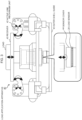
- Fig. 3 illustrates a load application apparatus 40.
- This load application apparatus 40 is configured of a receiver 41 for the load, an active link mechanism unit 42 which supports the receiver 41, an outer shell guide 43, and a sensor cover 44. Up and down actions of the active link mechanism unit 42 which supports both ends of the load receiver 41 make it possible to apply or eliminate the load at arbitrary time. Regarding the load placed on the receiver 41, only a vertical load (press-down force) is transmitted by the outer shell guide 43 to the load sensor 20 of the haptic detection apparatus 1. The positions on which the load acts are matched by engagement between a recess of the sensor cover 44 and a protrusion of a receiver shaft tip. By adjusting the recess position of the sensor cover 44, it is possible to apply the load to the load sensor 20 at an arbitrary position.
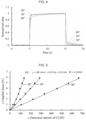
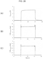
- Fig. 4 illustrates normalized results of outputs from Channel 1 (one of four first electrode plates 10) of the load sensor 20 when the load of 5.848 [N] was applied at the center position of each load sensor 20 for 10 seconds. It was confirmed based on these results that a response lag according to the hardness of the silicone rubber exists with the load sensor 20. Since the silicone rubber used as the rubber cylinder 12 is a viscoelastic body under this circumstance, gradual plastic deformation occurs after instantaneous elastic deformation. This plastic deformation is the cause of the response lag illustrated in Fig. 4 ; and you can see that as the rubber hardness is lower, the response lag becomes larger.
- Fig. 5 illustrates the relation between the sensor output one second after the load application, and the load.
- the load of 0 to 596.7 [g] is applied to the center position of the load sensor 20; and when and after the load becomes equal to or more than 96.7 [g], which is the weight of the load receiver of the load application apparatus, the load is increased by 100 [g] each time by adding counterweights; and five trials are conducted for the load application with respect to each load.
- Fig. 5 shows that as the rubber hardness of the rubber cylinder 12 becomes lower, the increase amount of the capacitance of the load sensor 20 becomes larger. This is because: as the rubber hardness becomes lower, the expansion/contraction amount of the rubber cylinder 12 relative to the load increases and the distance between the first electrode plate 10 and the second electrode plate 11 becomes shorter; and, therefore, the capacitance which has an inverse proportion relation with the distance between the first electrode plate 10 and the second electrode plate 11 becomes larger. Consequently, attention will be focused on the load sensor 20 with the rubber hardness 50[°], which was used to position the responsiveness and the sensor output among the three types of the load sensors 20, and the measurement characteristics will be checked and the calibration will be conducted.
- the calibration for the even load measurement of Channel 1 of the load sensor 20 is conducted by finding an approximate formula which represents a correlation from the plot of the load and the sensor output as illustrated in Fig. 5 , and using it for conversion between the sensor output and the load. Accordingly, the correction of size errors of the first electrode plate 10 and the second electrode plate 11 is conducted at the same time. Similarly, the calibration of other channels is also conducted. This time, high similarity was confirmed by a monotonically increasing quadratic curve within a response range for the applied load. Incidentally, a coefficient of determination R 2 was 0.999 or more with respect to all the channels.
- the characteristics of the sensor output when the uneven load is applied to the load sensor 20 will be examined from two points of view, that is, material characteristics of the rubber cylinder(s) 12 and electrical characteristics of the capacitor(s). Firstly, an explanation will be provided about the influence caused by the material characteristics of the rubber cylinder 12 when the uneven load is applied.
- the relation between the expansion/contraction amount of the rubber cylinder(s) 12 and the load as illustrated in Fig. 6 was calculated based on the relation between the sensor output and the load as illustrated in Fig. 5 which was confirmed with the aforementioned actual sensor.
- the load applied to one rubber cylinder 12 becomes a quarter of the total load.
- the material characteristics of common rubber materials including the silicone rubber the relation between the expansion/contraction amount and the load becomes non-linear.
- the coefficient of determination R 2 was 0.999 or more.
- the coefficient has a positive non-linear quadratic term when an input variable is the expansion/contraction amount and an output is the load
- the total sum of the expansion/contraction amount of the rubber cylinders 12 relative to the load becomes smaller with the uneven load, where the load is concentrated on part of the rubber cylinders 12, as compared to the even load.
- the capacitance is inversely proportional to the distance between the electrode plates, the influence caused by the material characteristics of the rubber cylinder(s) 12 is that, in the case of the uneven load, as the load center becomes farther away from the center of the sensor, the sensor output becomes smaller than that of the even load.
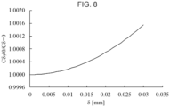
- Fig. 7 illustrates a sectional view of the capacitor in the case where an x-axis direction inclination ⁇ has occurred in the second electrode plate 11.
- the rubber cylinders 12 at both ends are linear springs in order to check only the influence caused by the electrical characteristics.
- ⁇ a relative dielectric constant of air
- ⁇ 0 a dielectric constant in vacuum
- a a long side of the sensor
- b a short side of the sensor.
- an x-axis direction length xd of an electrode plate edge capacitor which is reduced by the inclination is expressed by the following Expression (3).
- x d a ⁇ a 2 ⁇ 4 ⁇ 2 Therefore, the entire capacitance C is calculated according to Expression (4).
- C x ⁇ ⁇ a 2 ⁇ x d 2 a 2 ⁇ x d 2 ⁇ 0 bdx d ⁇ 2 ⁇ / a x
- the measurement characteristics for the uneven load are checked and the error compensation formula for the load measurement is derived by means of the simulation.
- Fig. 9(A) illustrates a bottom side view
- Fig. 9(B) illustrates a right side view of the case where the inclination has occurred in the second electrode plate 11 as a model of the load sensor 20 when the uneven load is applied.
- d 0 is a natural length of the rubber cylinder 12
- x d and y d are the lengths of the electrode plate edge capacitor in the x-axis direction and the y-axis direction, respectively, which are reduced by the inclination
- a' is the distance between the right and left electrode plates
- b' is the distance between the upper and lower electrode plates.
- the distributed load ratios will be defined as preparation for checking of the measurement characteristics for the uneven load and the derivation of the error compensation formula.
- the measured load distribution of the load sensor 20 is uniquely determined according to the applied load and its center position. By using this characteristic, the estimation and compensation of errors in the uneven load measurement become possible.
- Important information regarding the load distribution is the total load and the distributed load pattern.
- the method for deriving the total load F a is as described earlier.
- the distributed load pattern will be treated as an x-axis direction distributed load ratio R x and a y-axis direction distributed load ratio R y .
- R x and R y are expressed, respectively, as the following Expression (6) and the following Expression (7).
- R x 1 2 F ch 4 F ch 1 + F ch 4 + F ch 3 F ch 2 + F ch 3 ⁇ 0.5
- R y 1 2 F ch 2 F ch 1 + F ch 2 + F ch 3 F ch 3 + F ch 4 ⁇ 0.5
- This simulation is to: increase the load of 0 to 596.7 [g] in the same manner as the actual sensor by adding 100 [g] each time when and after the load reaches 96.7 [g]; and calculate F a and R x , R y when the load center is moved along the x-axis and the y-axis, respectively, from the center position of the load sensor 20.
- a necessary error compensation amount is calculated from the difference between a true value F true of the applied load and F a and this necessary error compensation amount is set as a vertical axis; and F a and R x are set as the respective axes of a bottom face coordinate system when the load center is moved along the x-axis, and F a and R y are set as the respective axes of the bottom face coordinate system when the load center is moved along the y-axis, thereby plotting them on a 3-dimensional graph.
- An approximate curved surface which is obtained by using F a and R x , R y as input variables and the error compensation amount as output with respect to data points which are plotted in this graph becomes the error compensation formula regarding the load measurement for the uneven load.
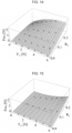
- Fig. 10 shows that the relation between F a , R x , and Fec x is uniquely determined according to the load and its applied position. Therefore, an approximate curved surface regarding which its input variables are F a and R x and its output is Fec x becomes the error compensation formula regarding the load measurement for the uneven load when the load center is moved in the x-axis positive direction. Under this circumstance, the error compensation is required when the inclination occurs in the upper-side electrode plate, that is, when R x is not 0; and, therefore, the function of F a will not solely influence the error compensation amount.
- the calculated approximate curved surface is illustrated in Fig. 10 .
- the error compensation formula can be calculated in the same manner as the case of the positive direction along the x-axis by using R y instead of R x .
- the calculated error compensation formula is indicated as the following Expression (9). Incidentally, the coefficient of determination R 2 of the approximate curved surface calculated as the error compensation formula was 0.986.
- the calculated approximate curved surface is illustrated in Fig. 11 .
- Fig. 12 illustrates a plot of data points on a 3-dimensional graph of F a , R xy , and Fec y calculated by the simulation.
- a polynomial (10) which is quadratic for F a and quadratic for R xy .
- the coefficient of determination R 2 was 1.
- the obtained polynomial (10) is indicated below. [Math.
- the calculated approximate curved surface is illustrated in Fig. 12 .
- the load was applied to 29 positions indicated in Fig. 13 in order to check the measurement characteristics for the uneven load in the actual sensor. It should be noted that the load of 0 to 569.7 [g] was applied by adding 100 [g] each time by using counterweights when and after the load reaches 96.7 [g] which is the weight of the load receiver of the load application apparatus.
- Fig. 14 illustrates a plot of data points on a 3-dimensional graph of F a , R xy , and Fec x of measured values when the load center of the load sensor 20 is moved 3 [mm] each time from 0 [mm] to 12 [mm] in the positive direction along the x-axis and a plot of the approximate curved surface according to the error compensation formula obtained from the simulation.
- Fig.15 illustrates a plot of data points on a 3-dimensional graph of F a , R y , and Fec y of measured values when the load center of the load sensor 20 is moved 3 [mm] each time from 0 [mm] to 6 [mm] in the positive direction along the y-axis and a plot of the approximate curved surface according to the error compensation formula obtained from the simulation.
- the rubber cylinders 12 are cylinders in the real model, so that when the electrode plates are inclined due to the uneven load, the force is concentrated on an edge part of the rubber cylinder 12 whose cross-sectional area is small. Accordingly, the expansion/contraction amount of the rubber cylinder 12 becomes larger than that of the simulation and the size of the necessary error compensation amount becomes small.
- the error compensation amount regarding the load measurement with the real model is kept smaller than that of the simulation due to the shape characteristics of the rubber cylinders 12. Furthermore, the difference in the characteristics from the simulation regarding a low load area when the load center is moved in the positive direction along the y-axis depends on the length of the electrode plate and is caused by an initial distortion of the second electrode plate 11, which is not considered in the simulation.
- the error compensation when the load center is moved in the positive direction along the x-axis was conducted by dividing a movement section by a mean value into a section from the center of the sensor to 6 [mm] and a section from 6 [mm] or higher, thereby calculating the coefficient parameters of Expression (8) and defining the error compensation formula.
- a minimum value of the decision constant R 2 was 0.946.
- the decision constant is lower when the error compensation formula is divided into two sections with respect to the x-coordinate of the load center; and this is because of the difference in the number of data used for the curved surface approximation and an improvement is recognized in terms of the measurement errors.
- a ceramic plate which is a light-weight insulator and has high hardness is used as a base material for the first electrode plate 10 and the second electrode plate 11.
- Fig. 16 illustrates a plot of the approximate curved surface according to the residual error compensation formula obtained from the simulation by plotting data points on a 3-dimensional graph of F a , R xy , and Fec xy of measured values when the load center of the load sensor 20 is moved along the diagonal line of the sensor in the positive directions along both the x-axis and the y-axis in the load sensor 20.
- the initial distortion of the second electrode plate 11 which is not considered in the simulation exists. So, it was decided to: divide the movement section into a section from the center of the sensor to 6 [mm] and a section from 6 [mm] or higher with respect to the x-coordinate of the load center in the same manner as the case where the load center is moved along the x-axis; and calculate the coefficient parameters of Expression (10) and define the residual error compensation formula. As a result, the minimum value of the coefficient of determination R 2 was 0.524, which showed an improvement.
- the load distribution to be measured is uniquely determined according to the load applied and its load center position, so that the total load F a , the x-axis direction distributed load ratio R x , and the y-axis direction distributed load ratio R y are also uniquely determined in the same manner. Therefore, it becomes possible to calculate the load center position from F a and R x , R y .
- the load center position calculation formula can be derived via the simulation by replacing the error compensation amount with the load center position upon the aforementioned derivation of the error compensation formula for the load measurement.
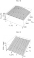
- Fig. 17 illustrates a plot of data points on a 3-dimensional graph of F a , R x , and the x-coordinate COF mx of the load center position which are calculated by the simulation.
- the calculated approximate curved surface is illustrated in Fig. 17 .
- the approximate curved surface can be also calculated with the coefficient of determination which is relatively high, by means of a polynomial which is linear for Fa and is linear for R x ; however, according to the present invention, it was decided to adopt Expression (12) which had a higher result of the coefficient of determination in order to realize the measurement of the load center position with higher accuracy.
- the calculation of the y-coordinate of the load center position will be examined when the load center of the load sensor 20 is moved 1 [mm] each time from 0 [mm] to 6 [mm] in the positive direction along the y-axis.
- the formula for calculating the y-coordinate of the load center position can be obtained in the same manner as the case of the positive direction along the x-axis by using R y instead of R x .
- Fig. 18 illustrates a plot of data points on a 3-dimensional graph of F a , R y , and the error compensation amount COF my of the y-coordinate of the load center position which are calculated by the simulation, and the obtained calculation formula is indicated in the following Expression (13).
- the coefficient of determination R 2 of the approximate curved surface obtained as the calculation formula was 0.999. [Math.
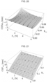
- Fig. 19 illustrates a plot of data points on a 3-dimensional graph of F a , R xy , and the error compensation amount COFec x of the x-coordinate of the load center position which are calculated by the simulation; and Fig. 20 illustrates a plot of data points on a 3-dimensional graph of F a , R xy , and the error compensation amount COFec y of the y-coordinate of the load center position.
- the calculated approximate curved surfaces are illustrated in Fig. 19 and Fig. 20 , respectively.
- a formula for calculating the load center position COF (x,y) of the load sensor 20 is the following Expression (16). [Math. 16]
- COF x y COF m x y + COFec x y
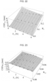
- Fig. 21 is a plot of data points on a 3-dimensional graph of F a , R x , and COF mx of measured values when the load center of the load sensor 20 is moved 3 [mm] each time from 0 [mm] to 12 [mm] in the positive direction along the x-axis, and a plot of the approximate curved surface according to the COF mx calculation formula obtained from the simulation.
- Fig. 22 is a plot of the approximate curved surface according to the COF my calculation formula obtained from the simulation by plotting data points on a 3-dimensional graph of F a , R y , and COF my of measured values when the load center of the load sensor 20 is moved 3 [mm] each time from 0 [mm] to 6 [mm] in the positive direction along the y-axis.
- Fig. 23 and Fig. 24 illustrate plots of approximate curved surfaces according to the error compensation formula obtained by the simulation by plotting data points on a 3-dimensional graph of F a , R xy , and COFec (x,y) of measured values when the load center of the load sensor 20 is moved along the diagonal line of the sensor in both the x-axis and y-axis positive directions.
- the coefficients of determination R 2 of the approximate curved surfaces were 0.290 and 0.939, respectively.
- the coefficient of determination of the approximate curved surface in Fig. 23 is low; and this is because the value of COFec x in the entire graph is small and, therefore, dispersion of the data points which derives from resolving power of the sensor is highly influential.
- the approximate curved surface has a high coefficient of determination relative to COFec y which has turned out to be a larger error compensation amount than COFec x , so that it is effective as the error compensation formula of the load center position.
- the load is applied to 29 positions indicated in Fig. 13 by using the load application apparatus and the measuring accuracy of the load sensor 20 is evaluated by using a measured value one second after the load application regarding which the calibration and the error compensation are conducted this time.
- the load of 0 to 596.7 [g] is applied by adding 100 g each time by using counterweights when and after the load reaches 96.7 g which is the weight of the load receiver of the load application apparatus; and five trials of the load application are conducted at each position and regarding each load.
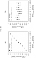
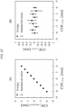
- Fig. 25(A) and Fig. 25(B) show measurement results of the load by the load sensor 20.
- Fig. 25(A) shows sample averages of the measured values and
- Fig. 25(B) shows sample averages of measurement errors. According to the experiment results, it was confirmed that with the load sensor 20 according to this embodiment, the sample averages of the errors were within the range of ⁇ 0.030 [N]. Incidentally, a maximum value of a standard deviation was 0.051 [N].
- Fig. 26 and Fig. 27 show measurement results of the x-coordinate COF x and the y-coordinate COF y of the load center position, respectively.
- Fig. 26 it was confirmed that the sample averages of the measurement errors of the x-coordinate were within the range of ⁇ 0.11 [mm]. Incidentally, a maximum standard deviation was 0.27 [mm].
- Fig. 27 it was confirmed that the sample averages of the measurement errors of the y-coordinate were within the range of ⁇ 0.12 [mm]. Incidentally, a maximum standard deviation was 0.29 [mm].
- the responses of the measured load and its load center position correspond to the applied load and its load center position.
- the haptic detection apparatus 1 is designed to include: the electrostatic-capacity-type load sensor 20 that forms a plurality of capacitors by inserting the same number of specified-shape cylinders, each of which is composed of a viscoelastic body, as the number of a plurality of positive electrodes of a first electrode plate 10, respectively between the first electrode plate 10 on which the plurality of positive electrodes are disposed in the same plane and in an array shape, and the second electrode plate 11 on which a single negative electrode is disposed; the capacitance detection unit 30 that detects capacitance of each of the capacitors which changes according to an external force applied to the second electrode plate 11 of the load sensor 20; the distributed load measurement unit 31 that measures a distributed load indicating a distribution of load applied to each of the rubber cylinders 12 on the basis of a change amount of the capacitance of each capacitor which is detected by the capacitance detection unit 30; and the load information calculation unit 32 that calculates a total load and a load center position of
- the distributed load applied to each rubber cylinder 12 is uniquely determined according to the total load and the load center position of the external force applied to the second electrode plate 11 of the load sensor 20, so that the size of the externally applied load can be measured accurately regardless of the planar dimension of the load which acts on the second electrode plate 11.
- the haptic detection apparatus 1 it was confirmed by the aforementioned measuring accuracy evaluation experiments by the actual sensor that the load sensor 20 can actually measure the load and the load center within the required load measurement range. Under this circumstance, if attention is focused on the measurement of the load center, it was successfully confirmed that the resolution for a stimulation position on a human finger's surface is approximately 1.6 [mm] and the load sensor 20 according to this embodiment has the measuring accuracy equal to or more than this.
- the capacitance detection unit 30 is designed, regarding each capacitor, to calibrate and correct a response lag according to a measurement error of the load applied to the rubber cylinder 12 according to material characteristics of the relevant rubber cylinder 12, and the hardness of the rubber cylinder 12 on the basis of an increase amount of the capacitance until an elapse of a specified amount of time after the application of the load.
- the response lag occurs attributable to gradual plastic deformation, which occurs after instantaneous elastic deformation, of the rubber cylinder(s) 12 which is the viscoelastic body, so that: the response lag becomes larger in proportion to a low level of the hardness; and as the hardness becomes lower, the expansion/contraction amount of the rubber cylinder 12 relative to the load increases and the distance between the first electrode plate 10 and the second electrode plate 11 becomes shorter and, therefore, the capacitance which has an inverse proportion relation with the distance between the first electrode plate 10 and the second electrode plate 11 becomes larger. So, the increase amount of the capacitance becomes larger in proportion to the low level of the hardness, but such factors based on the material characteristics can be solved.
- the response lag was confirmed regarding the measured load, but an improvement was confirmed with the response lag regarding the measured load center position. This is because components of the load division ratio are highly influential in the load center calculation formula and the influences of the response lag are offset each other in the load division ratio calculated from components of force of the measured load of each channel.
- the load information calculation unit 32 is designed to: calculate an error compensation amount for an uneven load, which causes the load center position to become outside the center of the second electrode plate 11, on the basis of the total load of the external force applied to the second electrode plate 11 of the load sensor 20, the distributed load ratio in the x-axis direction of the first electrode plate 10 as a plane surface, and the distributed load ratio in the y-axis direction of the first electrode plate 10 as the plane surface; and calibrates and corrects the load center position on the basis of the error compensation amount.
- the error compensation amount can be calculated by means of simulation also with respect to the uneven load which causes the load center position to become outside the center of the second electrode plate 11, and the load center position can be calibrated and corrected at the same time as the correction of the size error of each first electrode plate.
- the load sensor 20 is entirely coated with a shielding material which is made of a non-conducting material. As a result, it is possible to prevent the formation of a capacitor from the sensor itself and other dielectric substances and eliminate exogenous noise.
- this embodiment has described the case where the load sensor 20 for the haptic detection apparatus 1 is configured as the capacitance type which forms four capacitors by inserting the same number of rubber cylinders 12 as that of four positive electrodes of the first electrode plate 10, respectively, between the first electrode plate 10, on which the four positive electrodes are disposed in the same plane and in the array shape, and the second electrode plate 11 on which a single negative electrode is disposed; however, the present invention is not limited to this example and the number of positive electrodes on the first electrode plate 10 may be other than four and the first electrode plate 10 may be disposed in plurality.
- this embodiment has described the case where the rubber cylinder(s) 12 whose material is the silicone rubber is applied as the cylinder which is composed of a viscoelastic body to be inserted between the first electrode plate 10 and the second electrode plate 11; however, the present invention is not limited to this example and any materials other than the silicone rubber may be applied as long as such materials have excellent weather resistance, heat resistance, and cold resistance and have the hardness capable of securing a specified level or higher level of the responsiveness of the sensor output of the load sensor 20. If the enhancement of both the sensor's resolving power and responsiveness can be achieved, the present invention may be applied to a wide variety of materials other than those of the rubber cylinder 12.
- a robot arm may be configured by incorporating the haptic detection apparatus 1 according to this embodiment into fingertips for holding an object so that the second electrode plate 11 of the load sensor 20 serves as a holding surface of the fingertips for holding the object. Adjustments of the resolving power and the responsiveness can be realized by designing the size of the load sensor 20 by assuming the incorporation of the load sensor 20 into the finger part of the robot arm and adjusting the hardness and shape of the rubber cylinder(s) 12, so that it is expected to be utilized as a haptic sense of a robot for supporting human life. Furthermore, when this robot arm holds the object, it becomes possible to accurately recognize a contact pressure and contact positions at the fingertips.
Landscapes
- Engineering & Computer Science (AREA)
- Physics & Mathematics (AREA)
- General Physics & Mathematics (AREA)
- Robotics (AREA)
- Mechanical Engineering (AREA)
- Power Engineering (AREA)
- Human Computer Interaction (AREA)
- Chemical & Material Sciences (AREA)
- Analytical Chemistry (AREA)
- Force Measurement Appropriate To Specific Purposes (AREA)
Claims (7)
- Haptik-Detektionsvorrichtung (1), umfassend:einen Lastsensor (20) vom Kapazitätstyp, der eine Vielzahl von Kondensatoren durch Einfügen derselben Anzahl von Zylindern mit vorgegebener Form, von denen jeder aus einem viskoelastischen Körper besteht, wie die Anzahl einer Vielzahl von positiven Elektroden einer ersten Elektrodenplatte (10) jeweils zwischen die erste Elektrodenplatte (10), auf der die Vielzahl von positiven Elektroden in derselben Ebene und in einer Matrix-Form angeordnet sind, und eine zweite Elektrodenplatte (11), auf der eine einzelne negative Elektrode angeordnet ist, ausbildet;eine Kapazitätsdetektionseinheit (30), die die Kapazität jedes der Kondensatoren detektiert, die sich gemäß einer externen Kraft, mit der die zweite Elektrodenplatte (11) des Lastsensors (20) beaufschlagt wird, ändert;eine Messeinheit (31) für verteilte Last, die eine verteilte Last misst, die eine Lastverteilung angibt, die auf jeden der Zylinder basierend auf einem Änderungsausmaß der Kapazität jedes Kondensators, die durch die Kapazitätsdetektionseinheit (30) detektiert wird, beaufschlagt wird,gekennzeichnet durch eine Lastinformationsberechnungseinheit (32), die eine Gesamtlast und eine Lastmittelpunktposition der externen Kraft, mit der die zweite Elektrodenplatte (11) des Lastsensors (20) beaufschlagt wird, basierend auf einer Beziehung zwischen einem Ausdehnungs-/Kontraktionsausmaß jedes Zylinders relativ zu der verteilten Last, die durch die Messeinheit (31) für verteilte Last gemessen wird, und einem Muster der verteilten Last berechnet,wobei die Lastinformationsberechnungseinheit (32) ein Fehlerkompensationsausmaß für eine ungleichmäßige Last berechnet, welche die Lastmittelpunktposition nach außerhalb eines Mittelpunkts der zweiten Elektrodenplatte (11) verlagert, basierend auf der Gesamtlast der externen Kraft, mit der die zweite Elektrodenplatte (11) des Lastsensors (20) beaufschlagt wird, einem Verhältnis der verteilten Last in einer x-Achsenrichtung der ersten Elektrodenplatte (10) als eine ebene Oberfläche, und einem Verhältnis der verteilten Last in einer y-Achsenrichtung der ersten Elektrodenplatte (10) als die ebene Oberfläche, und die Lastmittelpunktposition basierend auf dem Fehlerkompensationsausmaß kalibriert und korrigiert.
- Haptik-Detektionsvorrichtung (1) nach Anspruch 1, wobei die Kapazitätsdetektionseinheit (30) in Hinblick auf jeden Kondensator eine Reaktionsverzögerung gemäß einem Messfehler der Last, mit der der Zylinder beaufschlagt wurde, gemäß Materialeigenschaften des jeweiligen Zylinders und einer Härte des Zylinders basierend auf einem Anstiegsausmaß der Kapazität kalibriert und korrigiert, bis eine angegebene Zeitspanne nach Beaufschlagen der Last verstrichen ist.
- Haptik-Detektionsvorrichtung (1) nach Anspruch 1 oder 2,
wobei der Lastsensor (20) vollständig mit einem Abschirmmaterial beschichtet ist, das aus einem nichtleitfähigen Material besteht. - Haptik-Detektionsverfahren mit einem Lastsensor (20) vom Kapazitätstyp, der ausgelegt ist, um eine Vielzahl von Kondensatoren durch Einfügen derselben Anzahl von Zylindern mit vorgegebener Form, von denen jeder aus einem viskoelastischen Körper besteht, wie die Anzahl einer Vielzahl von positiven Elektroden einer ersten Elektrodenplatte (10) jeweils zwischen die erste Elektrodenplatte (10), auf der die Vielzahl von positiven Elektroden in derselben Ebene und in einer Matrix-Form angeordnet sind, und eine zweite Elektrodenplatte (11), auf der eine einzelne negative Elektrode angeordnet ist, auszubilden;
wobei das Haptik-Detektionsverfahren Folgendes umfasst:einen ersten Schritt des Detektierens einer Kapazität jedes der Kondensatoren, die sich gemäß einer externen Kraft ändert, mit der die zweite Elektrodenplatte (11) des Lastsensors (20) beaufschlagt wird;einen zweiten Schritt des Messens einer verteilten Last, die eine Lastverteilung angibt, die auf jeden der Zylinder basierend auf einem Änderungsausmaß der Kapazität jedes Kondensators, das in dem ersten Schritt detektiert wird, angewendet wird,gekennzeichnet durch einen dritten Schritt des Berechnens einer Gesamtlast und einer Lastmittelpunktposition der externen Kraft, mit der die zweite Elektrodenplatte (11) des Lastsensors (20) beaufschlagt wird, basierend auf einer Beziehung zwischen einem Ausdehnungs-/Kontraktionsausmaß jedes Zylinders relativ zu der verteilten Last, die in dem zweiten Schritt gemessen wurde, und einem Muster der verteilten Last,wobei in dem dritten Schritt ein Fehlerkompensationsausmaß für eine ungleichmäßige Last, die eine Verlagerung der Lastmittelpunktposition nach außerhalb eines Mittelpunkts der zweiten Elektrodenplatte (11) bewirkt, berechnet wird, basierend auf der Gesamtlast der externen Kraft, mit der die zweite Elektrodenplatte (11) des Lastsensors (20) beaufschlagt wird, einem Verhältnis der verteilten Last in einer x-Achsenrichtung der ersten Elektrodenplatte (10) als eine ebene Oberfläche, und einem Verhältnis der verteilten Last in einer y-Achsenrichtung der ersten Elektrodenplatte (10) als die ebene Oberfläche und die Lastmittelpunktposition basierend auf dem Fehlerkompensationsausmaß kalibriert und korrigiert wird. - Haptik-Detektionsverfahren nach Anspruch 4, wobei in dem ersten Schritt in Hinblick auf jeden Kondensator eine Reaktionsverzögerung gemäß einem Messfehler der Last, mit der der Zylinder beaufschlagt wird, gemäß Materialeigenschaften des jeweiligen Zylinders und einer Härte des Zylinders basierend auf einem Anstiegsausmaß der Kapazität kalibriert und korrigiert wird, bis eine angegebene Zeitspanne nach Beaufschlagen der Last verstrichen ist.
- Haptik-Detektionsverfahren nach Anspruch 4 oder 5, wobei der Lastsensor (20) vollständig mit einem Abschirmmaterial beschichtet ist, das aus einem nichtleitfähigen Material besteht.
- Roboterarm mit einer Haptik-Detektionsvorrichtung (1) nach einem der Ansprüche 1 bis 3, die in dessen Fingerspitzen zum Halten eines Objekts eingebaut ist, sodass die zweite Elektrodenplatte (11) des Lastsensors (20) zu einer Halteoberfläche der Fingerspitzen wird.
Applications Claiming Priority (2)
| Application Number | Priority Date | Filing Date | Title |
|---|---|---|---|
| JP2019093192A JP7229095B2 (ja) | 2019-05-16 | 2019-05-16 | 触力覚検知装置、触力覚検知方法およびロボットアーム |
| PCT/JP2020/019282 WO2020230853A1 (ja) | 2019-05-16 | 2020-05-14 | 触力覚検知装置、触力覚検知方法およびロボットアーム |
Publications (3)
| Publication Number | Publication Date |
|---|---|
| EP3971545A1 EP3971545A1 (de) | 2022-03-23 |
| EP3971545A4 EP3971545A4 (de) | 2023-01-25 |
| EP3971545B1 true EP3971545B1 (de) | 2024-06-26 |
Family
ID=73220969
Family Applications (1)
| Application Number | Title | Priority Date | Filing Date |
|---|---|---|---|
| EP20805501.2A Active EP3971545B1 (de) | 2019-05-16 | 2020-05-14 | Detektor für taktile kraft, detektionsvorrichtung für taktile kraft und roboterarm |
Country Status (4)
| Country | Link |
|---|---|
| US (1) | US12123791B2 (de) |
| EP (1) | EP3971545B1 (de) |
| JP (1) | JP7229095B2 (de) |
| WO (1) | WO2020230853A1 (de) |
Families Citing this family (1)
| Publication number | Priority date | Publication date | Assignee | Title |
|---|---|---|---|---|
| CN121399560A (zh) | 2023-06-01 | 2026-01-23 | 阿尔卑斯阿尔派株式会社 | 输入装置 |
Family Cites Families (19)
| Publication number | Priority date | Publication date | Assignee | Title |
|---|---|---|---|---|
| JPH05288619A (ja) * | 1992-04-07 | 1993-11-02 | Youji Yamada | 静電容量式触覚センサ |
| JP5003336B2 (ja) * | 2007-07-31 | 2012-08-15 | ソニー株式会社 | 検出装置、ロボット装置、および入力装置 |
| JP2009069028A (ja) | 2007-09-13 | 2009-04-02 | Sony Corp | 検出装置および方法、プログラム、並びに記録媒体 |
| JP4565359B2 (ja) | 2008-08-08 | 2010-10-20 | 東海ゴム工業株式会社 | 静電容量型面圧分布センサ |
| US7958789B2 (en) | 2008-08-08 | 2011-06-14 | Tokai Rubber Industries, Ltd. | Capacitive sensor |
| US20100271328A1 (en) * | 2009-04-22 | 2010-10-28 | Shinji Sekiguchi | Input device and display device having the same |
| CN105022546B (zh) | 2009-06-11 | 2018-09-28 | 株式会社村田制作所 | 触摸面板以及触摸式输入装置 |
| JP4756097B1 (ja) | 2010-03-03 | 2011-08-24 | 株式会社オーギャ | 入力装置 |
| AU2011225730A1 (en) | 2010-03-12 | 2012-09-13 | Enhanced Surface Dynamics, Inc. | System and method for rapid data collection from pressure sensors in a pressure sensing system |
| JP6107811B2 (ja) * | 2012-03-09 | 2017-04-05 | ソニー株式会社 | センサ装置、入力装置及び電子機器 |
| GB201219632D0 (en) | 2012-10-31 | 2012-12-12 | Univ Southampton | Apparatus for sensing and measuring pressure and shear components of a force at an interface between two surfaces |
| JP2014142193A (ja) | 2013-01-22 | 2014-08-07 | Oga Inc | 荷重分布検出装置 |
| US10617327B2 (en) | 2014-11-06 | 2020-04-14 | Stryker Corporation | Exit detection system with compensation |
| KR101738864B1 (ko) | 2015-06-01 | 2017-05-23 | 주식회사 하이딥 | 터치 압력을 감지하는 터치 입력 장치의 감도 보정 방법 및 컴퓨터 판독 가능한 기록 매체 |
| US9868217B2 (en) | 2015-09-04 | 2018-01-16 | Univeristy Of Maryland | All-elastomer 3-axis contact resistive tactile sensor arrays and micromilled manufacturing methods thereof |
| KR101928902B1 (ko) * | 2015-11-26 | 2018-12-13 | 주식회사 모다이노칩 | 압력 센서, 이를 구비하는 복합 소자 및 전자기기 |
| US10101841B2 (en) | 2016-09-06 | 2018-10-16 | Apple Inc. | Electronic device diagnostics using force sensing assemblies |
| JP6763968B2 (ja) * | 2016-12-02 | 2020-09-30 | Cyberdyne株式会社 | 上肢動作支援装置及び上肢動作支援システム |
| JP2018190278A (ja) | 2017-05-10 | 2018-11-29 | パイオニア株式会社 | 操作入力装置 |
-
2019
- 2019-05-16 JP JP2019093192A patent/JP7229095B2/ja active Active
-
2020
- 2020-05-14 EP EP20805501.2A patent/EP3971545B1/de active Active
- 2020-05-14 US US17/611,620 patent/US12123791B2/en active Active
- 2020-05-14 WO PCT/JP2020/019282 patent/WO2020230853A1/ja not_active Ceased
Also Published As
| Publication number | Publication date |
|---|---|
| JP2020187069A (ja) | 2020-11-19 |
| EP3971545A1 (de) | 2022-03-23 |
| US20220244113A1 (en) | 2022-08-04 |
| US12123791B2 (en) | 2024-10-22 |
| WO2020230853A1 (ja) | 2020-11-19 |
| JP7229095B2 (ja) | 2023-02-27 |
| EP3971545A4 (de) | 2023-01-25 |
Similar Documents
| Publication | Publication Date | Title |
|---|---|---|
| US10088937B2 (en) | Touch input device including a moment compensated bending sensor for load measurement on platform supported by bending beams | |
| da Silva et al. | A strain gauge tactile sensor for finger-mounted applications | |
| US5054323A (en) | Pressure distribution characterization system | |
| US9453773B2 (en) | Capacitive type 6-axial force/torque sensor | |
| TWI531793B (zh) | 測定一感測器靈敏度的方法以及感測器,特別是磁場感測器 | |
| US20150177899A1 (en) | Elastomeric shear Material Providing Haptic Response Control | |
| CN103913264A (zh) | 检测装置、电子设备及机器人 | |
| US20050061082A1 (en) | Capacitive force sensing device | |
| US9335226B2 (en) | Force transducer forming a capacitive load cell | |
| CN105793686A (zh) | 输入装置以及输入装置的控制方法 | |
| US10101230B2 (en) | Reduction of non-linearity errors in automotive pressure sensors | |
| US12123791B2 (en) | Haptic detection apparatus, haptic detection method, and robot arm | |
| CN117705335B (zh) | 一种电感式可重构多维力传感器 | |
| KR101261137B1 (ko) | 탄성 유전체를 이용한 슬립센서 | |
| Kimoto et al. | A new multifunctional tactile sensor for detection of material hardness | |
| US6633172B1 (en) | Capacitive measuring sensor and method for operating same | |
| JP5700497B2 (ja) | 動作検出センサのキャリブレーション方法 | |
| Wolffenbuttel et al. | Compliant capacitive wrist sensor for use in industrial robots | |
| KR102060254B1 (ko) | 로드셀 및 멀티 로드셀 | |
| JP2006184098A (ja) | 感圧センサ | |
| Murakami et al. | Feasibility of novel four degrees of freedom capacitive force sensor for skin interface force | |
| KR101872433B1 (ko) | 온도보상 가능한 힘센서 | |
| KR20220110281A (ko) | 압력 감지 장치 | |
| KR102897046B1 (ko) | 단일구조 플렉셔 기반 3축 힘센서 | |
| US20240183723A1 (en) | Detection device |
Legal Events
| Date | Code | Title | Description |
|---|---|---|---|
| STAA | Information on the status of an ep patent application or granted ep patent |
Free format text: STATUS: THE INTERNATIONAL PUBLICATION HAS BEEN MADE |
|
| PUAI | Public reference made under article 153(3) epc to a published international application that has entered the european phase |
Free format text: ORIGINAL CODE: 0009012 |
|
| STAA | Information on the status of an ep patent application or granted ep patent |
Free format text: STATUS: REQUEST FOR EXAMINATION WAS MADE |
|
| 17P | Request for examination filed |
Effective date: 20211208 |
|
| AK | Designated contracting states |
Kind code of ref document: A1 Designated state(s): AL AT BE BG CH CY CZ DE DK EE ES FI FR GB GR HR HU IE IS IT LI LT LU LV MC MK MT NL NO PL PT RO RS SE SI SK SM TR |
|
| DAV | Request for validation of the european patent (deleted) | ||
| DAX | Request for extension of the european patent (deleted) | ||
| A4 | Supplementary search report drawn up and despatched |
Effective date: 20230102 |
|
| RIC1 | Information provided on ipc code assigned before grant |
Ipc: B25J 13/08 20060101ALI20221220BHEP Ipc: G06F 3/041 20060101ALI20221220BHEP Ipc: G01L 5/22 20060101ALI20221220BHEP Ipc: G01L 5/00 20060101ALI20221220BHEP Ipc: G01L 1/14 20060101AFI20221220BHEP |
|
| GRAP | Despatch of communication of intention to grant a patent |
Free format text: ORIGINAL CODE: EPIDOSNIGR1 |
|
| STAA | Information on the status of an ep patent application or granted ep patent |
Free format text: STATUS: GRANT OF PATENT IS INTENDED |
|
| INTG | Intention to grant announced |
Effective date: 20231222 |
|
| GRAS | Grant fee paid |
Free format text: ORIGINAL CODE: EPIDOSNIGR3 |
|
| GRAA | (expected) grant |
Free format text: ORIGINAL CODE: 0009210 |
|
| STAA | Information on the status of an ep patent application or granted ep patent |
Free format text: STATUS: THE PATENT HAS BEEN GRANTED |
|
| AK | Designated contracting states |
Kind code of ref document: B1 Designated state(s): AL AT BE BG CH CY CZ DE DK EE ES FI FR GB GR HR HU IE IS IT LI LT LU LV MC MK MT NL NO PL PT RO RS SE SI SK SM TR |
|
| REG | Reference to a national code |
Ref country code: GB Ref legal event code: FG4D |
|
| REG | Reference to a national code |
Ref country code: CH Ref legal event code: EP |
|
| REG | Reference to a national code |
Ref country code: DE Ref legal event code: R096 Ref document number: 602020033083 Country of ref document: DE |
|
| PG25 | Lapsed in a contracting state [announced via postgrant information from national office to epo] |
Ref country code: BG Free format text: LAPSE BECAUSE OF FAILURE TO SUBMIT A TRANSLATION OF THE DESCRIPTION OR TO PAY THE FEE WITHIN THE PRESCRIBED TIME-LIMIT Effective date: 20240626 |
|
| PG25 | Lapsed in a contracting state [announced via postgrant information from national office to epo] |
Ref country code: HR Free format text: LAPSE BECAUSE OF FAILURE TO SUBMIT A TRANSLATION OF THE DESCRIPTION OR TO PAY THE FEE WITHIN THE PRESCRIBED TIME-LIMIT Effective date: 20240626 Ref country code: FI Free format text: LAPSE BECAUSE OF FAILURE TO SUBMIT A TRANSLATION OF THE DESCRIPTION OR TO PAY THE FEE WITHIN THE PRESCRIBED TIME-LIMIT Effective date: 20240626 |
|
| REG | Reference to a national code |
Ref country code: LT Ref legal event code: MG9D |
|
| PG25 | Lapsed in a contracting state [announced via postgrant information from national office to epo] |
Ref country code: GR Free format text: LAPSE BECAUSE OF FAILURE TO SUBMIT A TRANSLATION OF THE DESCRIPTION OR TO PAY THE FEE WITHIN THE PRESCRIBED TIME-LIMIT Effective date: 20240927 |
|
| PG25 | Lapsed in a contracting state [announced via postgrant information from national office to epo] |
Ref country code: LV Free format text: LAPSE BECAUSE OF FAILURE TO SUBMIT A TRANSLATION OF THE DESCRIPTION OR TO PAY THE FEE WITHIN THE PRESCRIBED TIME-LIMIT Effective date: 20240626 |
|
| REG | Reference to a national code |
Ref country code: NL Ref legal event code: MP Effective date: 20240626 |
|
| PG25 | Lapsed in a contracting state [announced via postgrant information from national office to epo] |
Ref country code: NO Free format text: LAPSE BECAUSE OF FAILURE TO SUBMIT A TRANSLATION OF THE DESCRIPTION OR TO PAY THE FEE WITHIN THE PRESCRIBED TIME-LIMIT Effective date: 20240926 Ref country code: LV Free format text: LAPSE BECAUSE OF FAILURE TO SUBMIT A TRANSLATION OF THE DESCRIPTION OR TO PAY THE FEE WITHIN THE PRESCRIBED TIME-LIMIT Effective date: 20240626 Ref country code: HR Free format text: LAPSE BECAUSE OF FAILURE TO SUBMIT A TRANSLATION OF THE DESCRIPTION OR TO PAY THE FEE WITHIN THE PRESCRIBED TIME-LIMIT Effective date: 20240626 Ref country code: GR Free format text: LAPSE BECAUSE OF FAILURE TO SUBMIT A TRANSLATION OF THE DESCRIPTION OR TO PAY THE FEE WITHIN THE PRESCRIBED TIME-LIMIT Effective date: 20240927 Ref country code: FI Free format text: LAPSE BECAUSE OF FAILURE TO SUBMIT A TRANSLATION OF THE DESCRIPTION OR TO PAY THE FEE WITHIN THE PRESCRIBED TIME-LIMIT Effective date: 20240626 Ref country code: BG Free format text: LAPSE BECAUSE OF FAILURE TO SUBMIT A TRANSLATION OF THE DESCRIPTION OR TO PAY THE FEE WITHIN THE PRESCRIBED TIME-LIMIT Effective date: 20240626 Ref country code: RS Free format text: LAPSE BECAUSE OF FAILURE TO SUBMIT A TRANSLATION OF THE DESCRIPTION OR TO PAY THE FEE WITHIN THE PRESCRIBED TIME-LIMIT Effective date: 20240926 |
|
| PG25 | Lapsed in a contracting state [announced via postgrant information from national office to epo] |
Ref country code: NL Free format text: LAPSE BECAUSE OF FAILURE TO SUBMIT A TRANSLATION OF THE DESCRIPTION OR TO PAY THE FEE WITHIN THE PRESCRIBED TIME-LIMIT Effective date: 20240626 |
|
| REG | Reference to a national code |
Ref country code: AT Ref legal event code: MK05 Ref document number: 1698078 Country of ref document: AT Kind code of ref document: T Effective date: 20240626 |
|
| PG25 | Lapsed in a contracting state [announced via postgrant information from national office to epo] |
Ref country code: NL Free format text: LAPSE BECAUSE OF FAILURE TO SUBMIT A TRANSLATION OF THE DESCRIPTION OR TO PAY THE FEE WITHIN THE PRESCRIBED TIME-LIMIT Effective date: 20240626 |
|
| PG25 | Lapsed in a contracting state [announced via postgrant information from national office to epo] |
Ref country code: PT Free format text: LAPSE BECAUSE OF FAILURE TO SUBMIT A TRANSLATION OF THE DESCRIPTION OR TO PAY THE FEE WITHIN THE PRESCRIBED TIME-LIMIT Effective date: 20241028 |
|
| PG25 | Lapsed in a contracting state [announced via postgrant information from national office to epo] |
Ref country code: PT Free format text: LAPSE BECAUSE OF FAILURE TO SUBMIT A TRANSLATION OF THE DESCRIPTION OR TO PAY THE FEE WITHIN THE PRESCRIBED TIME-LIMIT Effective date: 20241028 |
|
| PG25 | Lapsed in a contracting state [announced via postgrant information from national office to epo] |
Ref country code: PL Free format text: LAPSE BECAUSE OF FAILURE TO SUBMIT A TRANSLATION OF THE DESCRIPTION OR TO PAY THE FEE WITHIN THE PRESCRIBED TIME-LIMIT Effective date: 20240626 |
|
| PG25 | Lapsed in a contracting state [announced via postgrant information from national office to epo] |
Ref country code: EE Free format text: LAPSE BECAUSE OF FAILURE TO SUBMIT A TRANSLATION OF THE DESCRIPTION OR TO PAY THE FEE WITHIN THE PRESCRIBED TIME-LIMIT Effective date: 20240626 |
|
| PG25 | Lapsed in a contracting state [announced via postgrant information from national office to epo] |
Ref country code: IS Free format text: LAPSE BECAUSE OF FAILURE TO SUBMIT A TRANSLATION OF THE DESCRIPTION OR TO PAY THE FEE WITHIN THE PRESCRIBED TIME-LIMIT Effective date: 20241026 Ref country code: AT Free format text: LAPSE BECAUSE OF FAILURE TO SUBMIT A TRANSLATION OF THE DESCRIPTION OR TO PAY THE FEE WITHIN THE PRESCRIBED TIME-LIMIT Effective date: 20240626 |
|
| PG25 | Lapsed in a contracting state [announced via postgrant information from national office to epo] |
Ref country code: CZ Free format text: LAPSE BECAUSE OF FAILURE TO SUBMIT A TRANSLATION OF THE DESCRIPTION OR TO PAY THE FEE WITHIN THE PRESCRIBED TIME-LIMIT Effective date: 20240626 |
|
| PG25 | Lapsed in a contracting state [announced via postgrant information from national office to epo] |
Ref country code: SK Free format text: LAPSE BECAUSE OF FAILURE TO SUBMIT A TRANSLATION OF THE DESCRIPTION OR TO PAY THE FEE WITHIN THE PRESCRIBED TIME-LIMIT Effective date: 20240626 Ref country code: RO Free format text: LAPSE BECAUSE OF FAILURE TO SUBMIT A TRANSLATION OF THE DESCRIPTION OR TO PAY THE FEE WITHIN THE PRESCRIBED TIME-LIMIT Effective date: 20240626 |
|
| PG25 | Lapsed in a contracting state [announced via postgrant information from national office to epo] |
Ref country code: ES Free format text: LAPSE BECAUSE OF FAILURE TO SUBMIT A TRANSLATION OF THE DESCRIPTION OR TO PAY THE FEE WITHIN THE PRESCRIBED TIME-LIMIT Effective date: 20240626 Ref country code: SM Free format text: LAPSE BECAUSE OF FAILURE TO SUBMIT A TRANSLATION OF THE DESCRIPTION OR TO PAY THE FEE WITHIN THE PRESCRIBED TIME-LIMIT Effective date: 20240626 |
|
| PG25 | Lapsed in a contracting state [announced via postgrant information from national office to epo] |
Ref country code: SM Free format text: LAPSE BECAUSE OF FAILURE TO SUBMIT A TRANSLATION OF THE DESCRIPTION OR TO PAY THE FEE WITHIN THE PRESCRIBED TIME-LIMIT Effective date: 20240626 Ref country code: SK Free format text: LAPSE BECAUSE OF FAILURE TO SUBMIT A TRANSLATION OF THE DESCRIPTION OR TO PAY THE FEE WITHIN THE PRESCRIBED TIME-LIMIT Effective date: 20240626 Ref country code: RO Free format text: LAPSE BECAUSE OF FAILURE TO SUBMIT A TRANSLATION OF THE DESCRIPTION OR TO PAY THE FEE WITHIN THE PRESCRIBED TIME-LIMIT Effective date: 20240626 Ref country code: PL Free format text: LAPSE BECAUSE OF FAILURE TO SUBMIT A TRANSLATION OF THE DESCRIPTION OR TO PAY THE FEE WITHIN THE PRESCRIBED TIME-LIMIT Effective date: 20240626 Ref country code: IS Free format text: LAPSE BECAUSE OF FAILURE TO SUBMIT A TRANSLATION OF THE DESCRIPTION OR TO PAY THE FEE WITHIN THE PRESCRIBED TIME-LIMIT Effective date: 20241026 Ref country code: ES Free format text: LAPSE BECAUSE OF FAILURE TO SUBMIT A TRANSLATION OF THE DESCRIPTION OR TO PAY THE FEE WITHIN THE PRESCRIBED TIME-LIMIT Effective date: 20240626 Ref country code: EE Free format text: LAPSE BECAUSE OF FAILURE TO SUBMIT A TRANSLATION OF THE DESCRIPTION OR TO PAY THE FEE WITHIN THE PRESCRIBED TIME-LIMIT Effective date: 20240626 Ref country code: CZ Free format text: LAPSE BECAUSE OF FAILURE TO SUBMIT A TRANSLATION OF THE DESCRIPTION OR TO PAY THE FEE WITHIN THE PRESCRIBED TIME-LIMIT Effective date: 20240626 Ref country code: AT Free format text: LAPSE BECAUSE OF FAILURE TO SUBMIT A TRANSLATION OF THE DESCRIPTION OR TO PAY THE FEE WITHIN THE PRESCRIBED TIME-LIMIT Effective date: 20240626 |
|
| REG | Reference to a national code |
Ref country code: DE Ref legal event code: R097 Ref document number: 602020033083 Country of ref document: DE |
|
| PG25 | Lapsed in a contracting state [announced via postgrant information from national office to epo] |
Ref country code: DK Free format text: LAPSE BECAUSE OF FAILURE TO SUBMIT A TRANSLATION OF THE DESCRIPTION OR TO PAY THE FEE WITHIN THE PRESCRIBED TIME-LIMIT Effective date: 20240626 |
|
| PLBE | No opposition filed within time limit |
Free format text: ORIGINAL CODE: 0009261 |
|
| STAA | Information on the status of an ep patent application or granted ep patent |
Free format text: STATUS: NO OPPOSITION FILED WITHIN TIME LIMIT |
|
| 26N | No opposition filed |
Effective date: 20250327 |
|
| PGFP | Annual fee paid to national office [announced via postgrant information from national office to epo] |
Ref country code: DE Payment date: 20250523 Year of fee payment: 6 |
|
| PGFP | Annual fee paid to national office [announced via postgrant information from national office to epo] |
Ref country code: IT Payment date: 20250526 Year of fee payment: 6 |
|
| PG25 | Lapsed in a contracting state [announced via postgrant information from national office to epo] |
Ref country code: SE Free format text: LAPSE BECAUSE OF FAILURE TO SUBMIT A TRANSLATION OF THE DESCRIPTION OR TO PAY THE FEE WITHIN THE PRESCRIBED TIME-LIMIT Effective date: 20240626 |
|
| REG | Reference to a national code |
Ref country code: CH Ref legal event code: H13 Free format text: ST27 STATUS EVENT CODE: U-0-0-H10-H13 (AS PROVIDED BY THE NATIONAL OFFICE) Effective date: 20251223 |
|
| PG25 | Lapsed in a contracting state [announced via postgrant information from national office to epo] |
Ref country code: LU Free format text: LAPSE BECAUSE OF NON-PAYMENT OF DUE FEES Effective date: 20250514 |
|
| PG25 | Lapsed in a contracting state [announced via postgrant information from national office to epo] |
Ref country code: CH Free format text: LAPSE BECAUSE OF NON-PAYMENT OF DUE FEES Effective date: 20250531 |
|
| REG | Reference to a national code |
Ref country code: BE Ref legal event code: MM Effective date: 20250531 |
|
| PG25 | Lapsed in a contracting state [announced via postgrant information from national office to epo] |
Ref country code: MC Free format text: LAPSE BECAUSE OF FAILURE TO SUBMIT A TRANSLATION OF THE DESCRIPTION OR TO PAY THE FEE WITHIN THE PRESCRIBED TIME-LIMIT Effective date: 20240626 |
|
| PGFP | Annual fee paid to national office [announced via postgrant information from national office to epo] |
Ref country code: GB Payment date: 20260330 Year of fee payment: 7 |
|
| PG25 | Lapsed in a contracting state [announced via postgrant information from national office to epo] |
Ref country code: IE Free format text: LAPSE BECAUSE OF NON-PAYMENT OF DUE FEES Effective date: 20250514 |
|
| PG25 | Lapsed in a contracting state [announced via postgrant information from national office to epo] |
Ref country code: BE Free format text: LAPSE BECAUSE OF NON-PAYMENT OF DUE FEES Effective date: 20250531 |
|
| PG25 | Lapsed in a contracting state [announced via postgrant information from national office to epo] |
Ref country code: FR Free format text: LAPSE BECAUSE OF NON-PAYMENT OF DUE FEES Effective date: 20250531 |