US12123791B2 - Haptic detection apparatus, haptic detection method, and robot arm - Google Patents
Haptic detection apparatus, haptic detection method, and robot arm Download PDFInfo
- Publication number
- US12123791B2 US12123791B2 US17/611,620 US202017611620A US12123791B2 US 12123791 B2 US12123791 B2 US 12123791B2 US 202017611620 A US202017611620 A US 202017611620A US 12123791 B2 US12123791 B2 US 12123791B2
- Authority
- US
- United States
- Prior art keywords
- load
- electrode plate
- sensor
- capacitance
- load sensor
- Prior art date
- Legal status (The legal status is an assumption and is not a legal conclusion. Google has not performed a legal analysis and makes no representation as to the accuracy of the status listed.)
- Active, expires
Links
Images


Classifications
-
- G—PHYSICS
- G01—MEASURING; TESTING
- G01L—MEASURING FORCE, STRESS, TORQUE, WORK, MECHANICAL POWER, MECHANICAL EFFICIENCY, OR FLUID PRESSURE
- G01L1/00—Measuring force or stress, in general
- G01L1/14—Measuring force or stress, in general by measuring variations in capacitance or inductance of electrical elements, e.g. by measuring variations of frequency of electrical oscillators
- G01L1/142—Measuring force or stress, in general by measuring variations in capacitance or inductance of electrical elements, e.g. by measuring variations of frequency of electrical oscillators using capacitors
- G01L1/146—Measuring force or stress, in general by measuring variations in capacitance or inductance of electrical elements, e.g. by measuring variations of frequency of electrical oscillators using capacitors for measuring force distributions, e.g. using force arrays
-
- B—PERFORMING OPERATIONS; TRANSPORTING
- B25—HAND TOOLS; PORTABLE POWER-DRIVEN TOOLS; MANIPULATORS
- B25J—MANIPULATORS; CHAMBERS PROVIDED WITH MANIPULATION DEVICES
- B25J13/00—Controls for manipulators
- B25J13/08—Controls for manipulators by means of sensing devices, e.g. viewing or touching devices
- B25J13/081—Touching devices, e.g. pressure-sensitive
- B25J13/082—Grasping-force detectors
-
- B—PERFORMING OPERATIONS; TRANSPORTING
- B25—HAND TOOLS; PORTABLE POWER-DRIVEN TOOLS; MANIPULATORS
- B25J—MANIPULATORS; CHAMBERS PROVIDED WITH MANIPULATION DEVICES
- B25J15/00—Gripping heads and other end effectors
- B25J15/08—Gripping heads and other end effectors having finger members
-
- G—PHYSICS
- G01—MEASURING; TESTING
- G01L—MEASURING FORCE, STRESS, TORQUE, WORK, MECHANICAL POWER, MECHANICAL EFFICIENCY, OR FLUID PRESSURE
- G01L5/00—Apparatus for, or methods of, measuring force, work, mechanical power, or torque, specially adapted for specific purposes
- G01L5/22—Apparatus for, or methods of, measuring force, work, mechanical power, or torque, specially adapted for specific purposes for measuring the force applied to control members, e.g. control members of vehicles, triggers
- G01L5/226—Apparatus for, or methods of, measuring force, work, mechanical power, or torque, specially adapted for specific purposes for measuring the force applied to control members, e.g. control members of vehicles, triggers to manipulators, e.g. the force due to gripping
- G01L5/228—Apparatus for, or methods of, measuring force, work, mechanical power, or torque, specially adapted for specific purposes for measuring the force applied to control members, e.g. control members of vehicles, triggers to manipulators, e.g. the force due to gripping using tactile array force sensors
-
- G—PHYSICS
- G06—COMPUTING OR CALCULATING; COUNTING
- G06F—ELECTRIC DIGITAL DATA PROCESSING
- G06F3/00—Input arrangements for transferring data to be processed into a form capable of being handled by the computer; Output arrangements for transferring data from processing unit to output unit, e.g. interface arrangements
- G06F3/01—Input arrangements or combined input and output arrangements for interaction between user and computer
- G06F3/03—Arrangements for converting the position or the displacement of a member into a coded form
- G06F3/041—Digitisers, e.g. for touch screens or touch pads, characterised by the transducing means
- G06F3/044—Digitisers, e.g. for touch screens or touch pads, characterised by the transducing means by capacitive means
- G06F3/0445—Digitisers, e.g. for touch screens or touch pads, characterised by the transducing means by capacitive means using two or more layers of sensing electrodes, e.g. using two layers of electrodes separated by a dielectric layer
Definitions
- the present invention is suited for application to a haptic detection apparatus, a haptic detection method, and a robot arm which are capable of feeding back haptic information.
- the robot In order for a robot arm to hold an object with appropriate force, it is necessary to control a gripping force while receiving the feedback of a contact pressure between fingertips and the object as haptic information. Furthermore, in order for the robot arm to judge whether the object is successfully held at the appropriate fingertip positions or not, it is necessary to recognize with which positions of the fingertips the object is in contact, on the basis of the contact positions between the fingertips and the object. Accordingly, the robot needs to be equipped with a haptic sensor capable of detecting information about the contact pressure and the contact positions at the fingertips of the robot arm.
- the robot(s) is required to work in the same environment at the same time as a person(s) without interrupting with the work environment or narrowing a work area.
- these requirements are satisfied; and, therefore, if the robot arm is of a size close to the size of a human arm, such requirements would be similarly satisfied.
- the haptic sensor needs to be designed with the size which allows the haptic sensor to be incorporated into finger parts of the robot arm.
- a capacitance-type surface pressure distribution sensor capable of detecting, for example, an uneven shape of an object to be measured as a surface pressure distribution on the basis of changes in the capacitance (see PTL 1).
- an input apparatus for detecting either a pressing direction or pressing strength, or both of them, according to changes in the capacitance when a thin resin film base on which capacitance detecting electrodes are formed is pressed at an arbitrary position (see PTL 2).
- a load distribution detection apparatus equipped with a capacitance-type surface pressure distribution sensor capable of detecting a load distribution by detecting the size of the load at each position (see PTL 3).
- each one of the above-mentioned PTL 1 to PTL 3 is characterized in that the relation between the pressure and the resistance of the pressure-sensitive conductive materials which are made of elastomers and/or resins does not become linear; and, therefore, even with the same load, the larger the area on which the load acts becomes, the larger a reduced amount of a resistance value becomes.
- the haptic sensor for robots Since there are various shapes of daily use items existing in the life scenes, a contact area of a finger surface in contact with a daily use item when holding the item is not constant. Therefore, the haptic sensor for robots, which can be used in the life scenes, is required to be capable of accurately measuring the size of the applied load regardless of the area on which the load acts.
- the present invention was devised in consideration of the above-described circumstances and proposes a haptic detection apparatus, a haptic detection method, and a robot arm which are capable of accurately measuring the size of the externally applied load regardless of the area on which the load acts.
- a haptic detection apparatus configured to include: a capacitance-type load sensor that forms a plurality of capacitors by inserting the same number of specified-shape cylinders, each of which is composed of a viscoelastic body, as the number of a plurality of positive electrodes of a first electrode plate, respectively between the first electrode plate on which the plurality of positive electrodes are disposed in the same plane and in an array shape, and a second electrode plate on which a single negative electrode is disposed; a capacitance detection unit that detects capacitance of each of the capacitors which changes according to an external force applied to the second electrode plate of the load sensor; a distributed load measurement unit that measures a distributed load indicating a distribution of load applied to each of the cylinders on the basis of a change amount of the capacitance of each capacitor which is detected by the capacitance detection unit; and a load information calculation unit that calculates a total load and a load center position of
- the distributed load applied to each cylinder is uniquely determined according to the total load and the load center position of the external force applied to the second electrode plate of the load sensor, so that the size of the externally applied load can be measured accurately regardless of the planar dimension of the load which acts on the second electrode plate.
- the capacitance detection unit calibrates and corrects a response lag according to a measurement error of the load applied to the cylinder according to material characteristics of the relevant cylinder, and hardness of the cylinder on the basis of an increase amount of the capacitance until an elapse of a specified amount of time after the application of the load.
- the response lag occurs attributable to gradual plastic deformation, which occurs after instantaneous elastic deformation, of the cylinder(s) which is the viscoelastic body, so that: the response lag becomes larger in proportion to a low level of the hardness; and as the hardness becomes lower, the expansion/contraction amount of the cylinder relative to the load increases and the distance between the electrode plates becomes shorter and, therefore, the capacitance which has an inverse proportion relation with the distance between the electrode plates becomes larger. So, the increase amount of the capacitance becomes larger in proportion to the low level of the hardness, but such factors based on the material characteristics can be solved.
- the load information calculation unit calculates an error compensation amount for an uneven load, which causes the load center position to become outside a center of the second electrode plate, on the basis of the total load of the external force applied to the second electrode plate of the load sensor, a ratio of the distributed load in an x-axis direction of the first electrode plate as a plane surface, and a ratio of the distributed load in a y-axis direction of the first electrode plate as the plane surface and calibrates and corrects the load center position on the basis of the error compensation amount.
- the error compensation amount can be calculated by means of simulation also with respect to the uneven load which causes the load center position to become outside the center of the second electrode plate, and the load center position can be calibrated and corrected at the same time as the correction of the size error of each first electrode plate.
- the load sensor is entirely coated with a shielding material which is made of a non-conducting material.
- a haptic detection method with a capacitance-type load sensor configured to form a plurality of capacitors by inserting the same number of specified-shape cylinders, each of which is composed of a viscoelastic body, as the number of a plurality of positive electrodes of a first electrode plate, respectively between the first electrode plate on which the plurality of positive electrodes are disposed in the same plane and in an array shape, and a second electrode plate on which a single negative electrode is disposed
- the haptic detection method includes: a first step of detecting capacitance of each of the capacitors which changes according to an external force applied to the second electrode plate of the load sensor; a second step of measuring a distributed load indicating a distribution of load applied to each of the cylinders on the basis of a change amount of the capacitance of each capacitor which is detected in the first step; and a third step of calculating a total load and a load center position of the external force applied to the second electrode plate of the
- the distributed load applied to each cylinder is uniquely determined according to the total load and the load center position of the external force applied to the second electrode plate of the load sensor, so that the size of the externally applied load can be measured accurately regardless of the planar dimension of the load which acts on the second electrode plate.
- a robot arm is configured to incorporate the haptic detection apparatus into its fingertips for holding an object so that the second electrode plate of the load sensor becomes a holding surface of the fingertips.
- the present invention as described above can implement the haptic detection apparatus, the haptic detection method, and the robot arm which are capable of accurately measuring the size of the externally applied load regardless of the planar dimension on which the load acts.
- FIGS. 1 A- 1 C are conceptual diagrams illustrating the configuration of a load sensor in a haptic detection apparatus according to this embodiment
- FIG. 2 is a block diagram illustrating an internal configuration of the haptic detection apparatus illustrated in FIG. 1 ;
- FIG. 3 is a schematic diagram illustrating an internal configuration of a load application apparatus
- FIG. 4 is a graph indicating a comparison of response characteristics when applying a load to center positions of three types of load sensors
- FIG. 5 is a graph indicating the relation between a sensor output one second after the load application, and the load;
- FIG. 6 is a graph indicating the relation between an expansion/contraction amount of a rubber cylinder and the load
- FIG. 7 is a schematic diagram illustrating a sectional view of a capacitor when an inclination ⁇ in an x-axis direction has occurred in a second electrode plate;
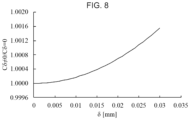
- FIG. 8 is a graph indicating a fluctuation coefficient of capacitance according to increase amounts of a center-to-center distance and the inclination of the second electrode plate;
- FIGS. 9 A and 9 B are conceptual diagrams illustrating a simulation model of the load sensor when an uneven load is applied
- FIG. 10 is a conceptual diagram illustrating a simulation model of the load sensor when the load center is moved in a positive direction along the x-axis;
- FIG. 11 is a conceptual diagram illustrating a simulation model of the load sensor when the load center is moved in a positive direction along the y-axis;
- FIG. 12 is a conceptual diagram illustrating a simulation model of the load sensor when the load center is moved in both x-axis and y-axis directions simultaneously;
- FIG. 13 is a schematic diagram indicating the relevant load applied positions in the load sensor
- FIG. 14 is a conceptual diagram illustrating a real model of the load sensor when the load center is moved in the positive direction along the x-axis;
- FIG. 15 is a conceptual diagram illustrating a real model of the load sensor when the load center is moved in the positive direction along the y-axis;
- FIG. 16 is a conceptual diagram illustrating a real model of the load sensor when the load center is moved in both x-axis and y-axis directions simultaneously;
- FIG. 17 is a conceptual diagram illustrating a simulation model of the load sensor when the load center is moved in the positive direction along the x-axis;
- FIG. 18 is a conceptual diagram illustrating a simulation model of the load sensor when the load center is moved in the positive direction along the y-axis;
- FIG. 19 is a conceptual diagram illustrating a simulation model after reflecting error compensation for the x-coordinates
- FIG. 20 is a conceptual diagram illustrating a simulation model after reflecting error compensation for the y-coordinates
- FIG. 21 is a conceptual diagram illustrating a simulation model of the load sensor when the load center is moved in the positive direction along the x-axis;
- FIG. 22 is a conceptual diagram illustrating a simulation model of the load sensor when the load center is moved in the positive direction along the y-axis;
- FIG. 23 is a conceptual diagram illustrating a simulation model after reflecting error compensation for the x-coordinates
- FIG. 24 is a conceptual diagram illustrating a simulation model after reflecting error compensation for the y-coordinates
- FIGS. 25 A and 25 B show graphs indicating load measurement results by the load sensor
- FIGS. 26 A and 26 B show graphs indicating measurement results of the x-coordinate at the load center position
- FIGS. 27 A and 27 B show graphs indicating measurement results of the y-coordinate at the load center position
- FIGS. 28 A- 28 C show graphs indicating continuous data of various types of measured values when the load is applied to the load sensor for 10 seconds.
- FIG. 1 A to FIG. 1 C illustrate a haptic detection apparatus 1 according to this embodiment.
- the haptic detection apparatus 1 includes a capacitance-type load sensor 20 which forms a plurality of capacitors by inserting the same number of rubber cylinders 12 of a specified shape as spacers, each of which is composed of a viscoelastic body, as the number of a plurality of positive electrodes of a first electrode plate 10 , respectively between the first electrode plate 10 on which the plurality of positive electrodes are disposed in the same plane and in an array shape, and a second electrode plate 11 on which a single negative electrode is disposed.
- the size of the load sensor 20 is set by assuming that finger parts of a robot arm (not shown in the drawings) are formed as a 2-link mechanism. Regarding the size of the second electrode plate 11 in the load sensor 20 , its long side is 30 [mm], its short side is 18 [mm], and its thickness is 2.3 [mm]; and the rubber cylinder 12 has a diameter of 2 [mm] and a height of 0.5 [mm].
- the load applied to the second electrode plate 11 of the load sensor 20 can be measured as a load distribution formed of four forces against the first electrode plate 10 , regardless of its contact area; and this load distribution makes it possible to calculate a total load applied to the load sensor 20 , and its load center position. As the distance between the electrodes is shorter, the capacitance appears as a large change (increase). So, the load sensor 20 which is highly sensitive and is of a thin type is appropriate for implementation.
- the load sensor 20 is structured to increase the expansion/contraction amount of the rubber cylinders 12 and enhance sensitivity of the sensor by concentrating the load on the rubber cylinders 12 disposed at four corners of the load sensor 20 .
- silicone rubber which has excellent weather resistance, heat resistance, and cold resistance is used as a material for the rubber cylinder 12 .
- the entire load sensor 20 is shielded and its back side is equipped and shielded with a measurement circuit. Consequently, the load sensor 20 is formed as a small-sized haptic sensor module capable of eliminating exogenous noise by preventing the formation of a capacitor between the first electrode plate 10 and the second electrode plate 11 and other dielectric substances and outputting ND-converted values in the vicinity of the first electrode plate 10 and the second electrode plate 11 .
- a load measurement range of the load sensor 20 is set in consideration of a gripping force which is required to hold daily use items in life scenes.
- ICF International Classification of Functioning, Disability, and Health
- a capacitance detection unit 30 detects the capacitance of each capacitor which changes according to an external force applied to the second electrode plate 11 of the load sensor 20 .
- a distributed load measurement unit 31 measures a distributed load indicating a distribution of the load applied to each rubber cylinder 12 on the basis of a change amount of the capacitance of each capacitor detected by the capacitance detection unit 30 .
- a load information calculation unit 32 calculates a total load and a load center position of an external force applied to the second electrode plate 11 of the load sensor 20 on the basis of the relation between an expansion/contraction amount of each rubber cylinder 12 relative to the distributed load measured by the distributed load measurement unit 31 , and a pattern of the distributed load.
- the capacitance detection unit 30 is designed as described later to calibrate and correct, with respect to each capacitor, a response lag according to a measurement error of the load applied to the rubber cylinder 12 according to material characteristics of the relevant cylinder, and hardness of the rubber cylinder 12 on the basis of an increase amount of the capacitance until the elapse of a specified amount of time after the application of the load.
- the load information calculation unit 32 is designed as described later to calculate an error compensation amount for an uneven load, which causes the load center position to become outside the center of the second electrode plate 11 , on the basis of the total load of the external force applied to the second electrode plate 11 of the load sensor 20 , a ratio of the distributed load in an x-axis direction of the first electrode plate 10 as a plane surface, and a ratio of the distributed load in a y-axis direction of the first electrode plate 10 as the plane surface and calibrate and correct the load center position on the basis of the error compensation amount.
- FIG. 3 illustrates a load application apparatus 40 .
- This load application apparatus 40 is configured of a receiver 41 for the load, an active link mechanism unit 42 which supports the receiver 41 , an outer shell guide 43 , and a sensor cover 44 .
- Up and down actions of the active link mechanism unit 42 which supports both ends of the load receiver 41 make it possible to apply or eliminate the load at arbitrary time.
- a vertical load is transmitted by the outer shell guide 43 to the load sensor 20 of the haptic detection apparatus 1 .
- the positions on which the load acts are matched by engagement between a recess of the sensor cover 44 and a protrusion of a receiver shaft tip. By adjusting the recess position of the sensor cover 44 , it is possible to apply the load to the load sensor 20 at an arbitrary position.
- FIG. 4 illustrates normalized results of outputs from Channel 1 (one of four first electrode plates 10 ) of the load sensor 20 when the load of 5.848 [N] was applied at the center position of each load sensor 20 for 10 seconds. It was confirmed based on these results that a response lag according to the hardness of the silicone rubber exists with the load sensor 20 . Since the silicone rubber used as the rubber cylinder 12 is a viscoelastic body under this circumstance, gradual plastic deformation occurs after instantaneous elastic deformation. This plastic deformation is the cause of the response lag illustrated in FIG. 4 ; and you can see that as the rubber hardness is lower, the response lag becomes larger.
- FIG. 5 illustrates the relation between the sensor output one second after the load application, and the load.
- the load of 0 to 596.7 [g] is applied to the center position of the load sensor 20 ; and when and after the load becomes equal to or more than 96.7 [g], which is the weight of the load receiver of the load application apparatus, the load is increased by 100 [g] each time by adding counterweights; and five trials are conducted for the load application with respect to each load.
- FIG. 5 shows that as the rubber hardness of the rubber cylinder 12 becomes lower, the increase amount of the capacitance of the load sensor 20 becomes larger. This is because: as the rubber hardness becomes lower, the expansion/contraction amount of the rubber cylinder 12 relative to the load increases and the distance between the first electrode plate 10 and the second electrode plate 11 becomes shorter; and, therefore, the capacitance which has an inverse proportion relation with the distance between the first electrode plate 10 and the second electrode plate 11 becomes larger. Consequently, attention will be focused on the load sensor 20 with the rubber hardness 50 [° ], which was used to position the responsiveness and the sensor output among the three types of the load sensors 20 , and the measurement characteristics will be checked and the calibration will be conducted.
- the calibration for the even load measurement of Channel 1 of the load sensor 20 is conducted by finding an approximate formula which represents a correlation from the plot of the load and the sensor output as illustrated in FIG. 5 , and using it for conversion between the sensor output and the load. Accordingly, the correction of size errors of the first electrode plate 10 and the second electrode plate 11 is conducted at the same time. Similarly, the calibration of other channels is also conducted. This time, high similarity was confirmed by a monotonically increasing quadratic curve within a response range for the applied load. Incidentally, a coefficient of determination R 2 was 0.999 or more with respect to all the channels.
- the characteristics of the sensor output when the uneven load is applied to the load sensor 20 will be examined from two points of view, that is, material characteristics of the rubber cylinder(s) 12 and electrical characteristics of the capacitor(s). Firstly, an explanation will be provided about the influence caused by the material characteristics of the rubber cylinder 12 when the uneven load is applied.
- the relation between the expansion/contraction amount of the rubber cylinder(s) 12 and the load as illustrated in FIG. 6 was calculated based on the relation between the sensor output and the load as illustrated in FIG. 5 which was confirmed with the aforementioned actual sensor.
- the load applied to one rubber cylinder 12 becomes a quarter of the total load.
- the material characteristics of common rubber materials including the silicone rubber the relation between the expansion/contraction amount and the load becomes non-linear.
- the coefficient of determination R 2 was 0.999 or more.
- the coefficient has a positive non-linear quadratic term when an input variable is the expansion/contraction amount and an output is the load
- the total sum of the expansion/contraction amount of the rubber cylinders 12 relative to the load becomes smaller with the uneven load, where the load is concentrated on part of the rubber cylinders 12 , as compared to the even load.
- the capacitance is inversely proportional to the distance between the electrode plates, the influence caused by the material characteristics of the rubber cylinder(s) 12 is that, in the case of the uneven load, as the load center becomes farther away from the center of the sensor, the sensor output becomes smaller than that of the even load.
- FIG. 7 illustrates a sectional view of the capacitor in the case where an x-axis direction inclination ⁇ has occurred in the second electrode plate 11 .
- the rubber cylinders 12 at both ends are linear springs in order to check only the influence caused by the electrical characteristics.
- c represents a relative dielectric constant of air
- ⁇ 0 represents a dielectric constant in vacuum
- a represents a long side of the sensor
- b represents a short side of the sensor.
- an x-axis direction length xd of an electrode plate edge capacitor which is reduced by the inclination is expressed by the following Expression (3).
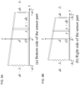
- FIG. 9 A illustrates a bottom side view
- FIG. 9 B illustrates a right side view of the case where the inclination has occurred in the second electrode plate 11 as a model of the load sensor 20 when the uneven load is applied.
- x d and y d are the lengths of the electrode plate edge capacitor in the x-axis direction and the y-axis direction, respectively, which are reduced by the inclination
- a′ is the distance between the right and left electrode plates
- b′ is the distance between the upper and lower electrode plates.
- the distributed load ratios will be defined as preparation for checking of the measurement characteristics for the uneven load and the derivation of the error compensation formula.
- the measured load distribution of the load sensor 20 is uniquely determined according to the applied load and its center position. By using this characteristic, the estimation and compensation of errors in the uneven load measurement become possible.
- Important information regarding the load distribution is the total load and the distributed load pattern.
- the method for deriving the total load Fa is as described earlier.
- the distributed load pattern will be treated as an x-axis direction distributed load ratio R x and a y-axis direction distributed load ratio R y .
- R x and R y are expressed, respectively, as the following Expression (6) and the following Expression (7).
- the value of R x becomes 0 when there is no inclination in the x-axis direction
- the value of R y becomes 0 when there is no inclination in the y-axis direction.
- the total load Fa, the x-axis direction distributed load ratio R x , and the y-axis direction distributed load ratio R y are also uniquely determined in the same manner. Therefore, if a necessary error compensation amount can be derived from Fa and R x , R y , the error compensation becomes possible regarding the load measurement for the uneven load.
- This simulation is to: increase the load of 0 to 596.7 [g] in the same manner as the actual sensor by adding 100 [g] each time when and after the load reaches 96.7 [g]; and calculate F a and R x , R y when the load center is moved along the x-axis and the y-axis, respectively, from the center position of the load sensor 20 .
- a necessary error compensation amount is calculated from the difference between a true value F true of the applied load and F a and this necessary error compensation amount is set as a vertical axis; and F a and R x are set as the respective axes of a bottom face coordinate system when the load center is moved along the x-axis, and F a and R y are set as the respective axes of the bottom face coordinate system when the load center is moved along the y-axis, thereby plotting them on a 3-dimensional graph.
- An approximate curved surface which is obtained by using F a and R x , R y as input variables and the error compensation amount as output with respect to data points which are plotted in this graph becomes the error compensation formula regarding the load measurement for the uneven load.
- FIG. 10 shows that the relation between F a , R x , and Fec x is uniquely determined according to the load and its applied position. Therefore, an approximate curved surface regarding which its input variables are F a and R x and its output is Fec x becomes the error compensation formula regarding the load measurement for the uneven load when the load center is moved in the x-axis positive direction. Under this circumstance, the error compensation is required when the inclination occurs in the upper-side electrode plate, that is, when R x is not 0; and, therefore, the function of F a will not solely influence the error compensation amount.
- the calculated approximate curved surface is illustrated in FIG. 10 .
- the calculated error compensation formula is indicated as the following Expression (9). Incidentally, the coefficient of determination R 2 of the approximate curved surface calculated as the error compensation formula was 0.986.
- the calculated approximate curved surface is illustrated in FIG. 11 .
- FIG. 12 illustrates a plot of data points on a 3-dimensional graph of F a , R xy , and Fec y calculated by the simulation.
- a polynomial (10) which is quadratic for F a and quadratic for R xy .
- the coefficient of determination R 2 was 1.
- the obtained polynomial (10) is indicated below.
- the calculated approximate curved surface is illustrated in FIG. 12 .
- the load was applied to 29 positions indicated in FIG. 13 in order to check the measurement characteristics for the uneven load in the actual sensor. It should be noted that the load of 0 to 569.7 [g] was applied by adding 100 [g] each time by using counterweights when and after the load reaches 96.7 [g] which is the weight of the load receiver of the load application apparatus.
- FIG. 14 illustrates a plot of data points on a 3-dimensional graph of F a , R xy , and Fec x of measured values when the load center of the load sensor 20 is moved 3 [mm] each time from 0 [mm] to 12 [mm] in the positive direction along the x-axis and a plot of the approximate curved surface according to the error compensation formula obtained from the simulation.
- FIG. 15 illustrates a plot of data points on a 3-dimensional graph of F a , R y , and Fec y of measured values when the load center of the load sensor 20 is moved 3 [mm] each time from 0 [mm] to 6 [mm] in the positive direction along the y-axis and a plot of the approximate curved surface according to the error compensation formula obtained from the simulation.
- the reason why the size of the error compensation amount in FIG. 14 and FIG. 15 is smaller than that of the simulation is that springs were used for the simulation without consideration of the shape of the rubber cylinder(s) 12 .
- the rubber cylinders 12 are cylinders in the real model, so that when the electrode plates are inclined due to the uneven load, the force is concentrated on an edge part of the rubber cylinder 12 whose cross-sectional area is small. Accordingly, the expansion/contraction amount of the rubber cylinder 12 becomes larger than that of the simulation and the size of the necessary error compensation amount becomes small.
- the error compensation amount regarding the load measurement with the real model is kept smaller than that of the simulation due to the shape characteristics of the rubber cylinders 12 . Furthermore, the difference in the characteristics from the simulation regarding a low load area when the load center is moved in the positive direction along the y-axis depends on the length of the electrode plate and is caused by an initial distortion of the second electrode plate 11 , which is not considered in the simulation.
- the error compensation when the load center is moved in the positive direction along the x-axis was conducted by dividing a movement section by a mean value into a section from the center of the sensor to 6 [mm] and a section from 6 [mm] or higher, thereby calculating the coefficient parameters of Expression (8) and defining the error compensation formula.
- a minimum value of the decision constant R 2 was 0.946.
- the decision constant is lower when the error compensation formula is divided into two sections with respect to the x-coordinate of the load center; and this is because of the difference in the number of data used for the curved surface approximation and an improvement is recognized in terms of the measurement errors.
- a ceramic plate which is a light-weight insulator and has high hardness is used as a base material for the first electrode plate 10 and the second electrode plate 11 .
- FIG. 16 illustrates a plot of the approximate curved surface according to the residual error compensation formula obtained from the simulation by plotting data points on a 3-dimensional graph of F a , R xy , and Fec xy of measured values when the load center of the load sensor 20 is moved along the diagonal line of the sensor in the positive directions along both the x-axis and the y-axis in the load sensor 20 .
- the initial distortion of the second electrode plate 11 which is not considered in the simulation exists. So, it was decided to: divide the movement section into a section from the center of the sensor to 6 [mm] and a section from 6 [mm] or higher with respect to the x-coordinate of the load center in the same manner as the case where the load center is moved along the x-axis; and calculate the coefficient parameters of Expression (10) and define the residual error compensation formula. As a result, the minimum value of the coefficient of determination R 2 was 0.524, which showed an improvement.
- the load distribution to be measured is uniquely determined according to the load applied and its load center position, so that the total load F a , the x-axis direction distributed load ratio R x , and the y-axis direction distributed load ratio R y are also uniquely determined in the same manner. Therefore, it becomes possible to calculate the load center position from F a and R x , R y .
- the load center position calculation formula can be derived via the simulation by replacing the error compensation amount with the load center position upon the aforementioned derivation of the error compensation formula for the load measurement.
- FIG. 17 illustrates a plot of data points on a 3-dimensional graph of F a , R x , and the x-coordinate COF mx of the load center position which are calculated by the simulation.
- the calculated approximate curved surface is illustrated in FIG. 17 .
- the approximate curved surface can be also calculated with the coefficient of determination which is relatively high, by means of a polynomial which is linear for F a and is linear for R x ; however, according to the present invention, it was decided to adopt Expression (12) which had a higher result of the coefficient of determination in order to realize the measurement of the load center position with higher accuracy.
- the calculation of the y-coordinate of the load center position will be examined when the load center of the load sensor 20 is moved 1 [mm] each time from 0 [mm] to 6 [mm] in the positive direction along the y-axis.
- the formula for calculating the y-coordinate of the load center position can be obtained in the same manner as the case of the positive direction along the x-axis by using R y instead of R x .
- FIG. 18 illustrates a plot of data points on a 3-dimensional graph of F a , R y , and the error compensation amount COF my of the y-coordinate of the load center position which are calculated by the simulation, and the obtained calculation formula is indicated in the following Expression (13).
- the coefficient of determination R 2 of the approximate curved surface obtained as the calculation formula was 0.999.
- the calculated approximate curved surface is illustrated in FIG. 18 .
- FIG. 19 illustrates a plot of data points on a 3-dimensional graph of F a , R xy , and the error compensation amount COFec x of the x-coordinate of the load center position which are calculated by the simulation; and
- FIG. 20 illustrates a plot of data points on a 3-dimensional graph of F a , R xy , and the error compensation amount COFec y of the y-coordinate of the load center position.
- each of u n and v n is a coefficient of each term of the derived error compensation formula for measuring the load center position; and also when the movement of the load center is changed from the second quadrant to the fourth quadrant, the error compensation formula can be similarly calculated by separately calculating these parameters in each case.
- the calculated approximate curved surfaces are illustrated in FIG. 19 and FIG. 20 , respectively.
- a formula for calculating the load center position COF (x,y) of the load sensor 20 is the following Expression (16).
- FIG. 21 is a plot of data points on a 3-dimensional graph of F a , R x , and COF mx of measured values when the load center of the load sensor 20 is moved 3 [mm] each time from 0 [mm] to 12 [mm] in the positive direction along the x-axis, and a plot of the approximate curved surface according to the COF mx calculation formula obtained from the simulation.
- FIG. 22 is a plot of the approximate curved surface according to the COF my calculation formula obtained from the simulation by plotting data points on a 3-dimensional graph of F a , R y , and COF my of measured values when the load center of the load sensor 20 is moved 3 [mm] each time from 0 [mm] to 6 [mm] in the positive direction along the y-axis.
- FIG. 23 and FIG. 24 illustrate plots of approximate curved surfaces according to the error compensation formula obtained by the simulation by plotting data points on a 3-dimensional graph of F a , R xy , and COFec (x,y) of measured values when the load center of the load sensor 20 is moved along the diagonal line of the sensor in both the x-axis and y-axis positive directions.
- the coefficients of determination R 2 of the approximate curved surfaces were 0.290 and 0.939, respectively.
- the coefficient of determination of the approximate curved surface in FIG. 23 is low; and this is because the value of COFec x in the entire graph is small and, therefore, dispersion of the data points which derives from resolving power of the sensor is highly influential.
- the approximate curved surface has a high coefficient of determination relative to COFec y which has turned out to be a larger error compensation amount than COFec x , so that it is effective as the error compensation formula of the load center position.
- the load is applied to 29 positions indicated in FIG. 13 by using the load application apparatus and the measuring accuracy of the load sensor 20 is evaluated by using a measured value one second after the load application regarding which the calibration and the error compensation are conducted this time.
- the load of 0 to 596.7 [g] is applied by adding 100 g each time by using counterweights when and after the load reaches 96.7 g which is the weight of the load receiver of the load application apparatus; and five trials of the load application are conducted at each position and regarding each load.
- FIG. 25 A and FIG. 25 B show measurement results of the load by the load sensor 20 .
- FIG. 25 A shows sample averages of the measured values and
- FIG. 25 B shows sample averages of measurement errors. According to the experiment results, it was confirmed that with the load sensor 20 according to this embodiment, the sample averages of the errors were within the range of ⁇ 0.030 [N]. Incidentally, a maximum value of a standard deviation was 0.051 [N].
- FIG. 26 and FIG. 27 show measurement results of the x-coordinate COF x and the y-coordinate COF y of the load center position, respectively.
- FIG. 26 it was confirmed that the sample averages of the measurement errors of the x-coordinate were within the range of ⁇ 0.11 [mm]. Incidentally, a maximum standard deviation was 0.27 [mm].
- FIG. 27 it was confirmed that the sample averages of the measurement errors of the y-coordinate were within the range of ⁇ 0.12 [mm]. Incidentally, a maximum standard deviation was 0.29 [mm].
- FIG. 28 A to FIG. 28 C it was confirmed that the responses of the measured load and its load center position correspond to the applied load and its load center position.
- the haptic detection apparatus 1 is designed to include: the electrostatic-capacity-type load sensor 20 that forms a plurality of capacitors by inserting the same number of specified-shape cylinders, each of which is composed of a viscoelastic body, as the number of a plurality of positive electrodes of a first electrode plate 10 , respectively between the first electrode plate 10 on which the plurality of positive electrodes are disposed in the same plane and in an array shape, and the second electrode plate 11 on which a single negative electrode is disposed; the capacitance detection unit 30 that detects capacitance of each of the capacitors which changes according to an external force applied to the second electrode plate 11 of the load sensor 20 ; the distributed load measurement unit 31 that measures a distributed load indicating a distribution of load applied to each of the rubber cylinders 12 on the basis of a change amount of the capacitance of each capacitor which is detected by the capacitance detection unit 30 ; and the load information calculation unit 32 that calculates a total load and a
- the distributed load applied to each rubber cylinder 12 is uniquely determined according to the total load and the load center position of the external force applied to the second electrode plate 11 of the load sensor 20 , so that the size of the externally applied load can be measured accurately regardless of the planar dimension of the load which acts on the second electrode plate 11 .
- the haptic detection apparatus 1 it was confirmed by the aforementioned measuring accuracy evaluation experiments by the actual sensor that the load sensor 20 can actually measure the load and the load center within the required load measurement range. Under this circumstance, if attention is focused on the measurement of the load center, it was successfully confirmed that the resolution for a stimulation position on a human finger's surface is approximately 1.6 [mm] and the load sensor 20 according to this embodiment has the measuring accuracy equal to or more than this.
- the capacitance detection unit 30 is designed, regarding each capacitor, to calibrate and correct a response lag according to a measurement error of the load applied to the rubber cylinder 12 according to material characteristics of the relevant rubber cylinder 12 , and the hardness of the rubber cylinder 12 on the basis of an increase amount of the capacitance until an elapse of a specified amount of time after the application of the load.
- the response lag occurs attributable to gradual plastic deformation, which occurs after instantaneous elastic deformation, of the rubber cylinder(s) 12 which is the viscoelastic body, so that: the response lag becomes larger in proportion to a low level of the hardness; and as the hardness becomes lower, the expansion/contraction amount of the rubber cylinder 12 relative to the load increases and the distance between the first electrode plate 10 and the second electrode plate 11 becomes shorter and, therefore, the capacitance which has an inverse proportion relation with the distance between the first electrode plate 10 and the second electrode plate 11 becomes larger. So, the increase amount of the capacitance becomes larger in proportion to the low level of the hardness, but such factors based on the material characteristics can be solved.
- the response lag was confirmed regarding the measured load, but an improvement was confirmed with the response lag regarding the measured load center position. This is because components of the load division ratio are highly influential in the load center calculation formula and the influences of the response lag are offset each other in the load division ratio calculated from components of force of the measured load of each channel.
- the resolving power of the sensor and the responsiveness are in a trade-off relationship; however, by reducing the diameter or height of the rubber cylinder 12 , the increase amount of the capacitance by the load application can be made larger even when using the silicone rubber with high hardness, so that the enhancement of both the resolving power and the responsiveness can be achieved.
- the load information calculation unit 32 is designed to: calculate an error compensation amount for an uneven load, which causes the load center position to become outside the center of the second electrode plate 11 , on the basis of the total load of the external force applied to the second electrode plate 11 of the load sensor 20 , the distributed load ratio in the x-axis direction of the first electrode plate 10 as a plane surface, and the distributed load ratio in the y-axis direction of the first electrode plate 10 as the plane surface; and calibrates and corrects the load center position on the basis of the error compensation amount.
- the error compensation amount can be calculated by means of simulation also with respect to the uneven load which causes the load center position to become outside the center of the second electrode plate 11 , and the load center position can be calibrated and corrected at the same time as the correction of the size error of each first electrode plate.
- the load sensor 20 is entirely coated with a shielding material which is made of a non-conducting material. As a result, it is possible to prevent the formation of a capacitor from the sensor itself and other dielectric substances and eliminate exogenous noise.
- this embodiment has described the case where the load sensor 20 for the haptic detection apparatus 1 is configured as the capacitance type which forms four capacitors by inserting the same number of rubber cylinders 12 as that of four positive electrodes of the first electrode plate 10 , respectively, between the first electrode plate 10 , on which the four positive electrodes are disposed in the same plane and in the array shape, and the second electrode plate 11 on which a single negative electrode is disposed; however, the present invention is not limited to this example and the number of positive electrodes on the first electrode plate 10 may be other than four and the first electrode plate 10 may be disposed in plurality.
- this embodiment has described the case where the rubber cylinder(s) 12 whose material is the silicone rubber is applied as the cylinder which is composed of a viscoelastic body to be inserted between the first electrode plate 10 and the second electrode plate 11 ; however, the present invention is not limited to this example and any materials other than the silicone rubber may be applied as long as such materials have excellent weather resistance, heat resistance, and cold resistance and have the hardness capable of securing a specified level or higher level of the responsiveness of the sensor output of the load sensor 20 . If the enhancement of both the sensor's resolving power and responsiveness can be achieved, the present invention may be applied to a wide variety of materials other than those of the rubber cylinder 12 .
- a robot arm may be configured by incorporating the haptic detection apparatus 1 according to this embodiment into fingertips for holding an object so that the second electrode plate 11 of the load sensor 20 serves as a holding surface of the fingertips for holding the object. Adjustments of the resolving power and the responsiveness can be realized by designing the size of the load sensor 20 by assuming the incorporation of the load sensor 20 into the finger part of the robot arm and adjusting the hardness and shape of the rubber cylinder(s) 12 , so that it is expected to be utilized as a haptic sense of a robot for supporting human life. Furthermore, when this robot arm holds the object, it becomes possible to accurately recognize a contact pressure and contact positions at the fingertips.
Landscapes
- Engineering & Computer Science (AREA)
- Physics & Mathematics (AREA)
- General Physics & Mathematics (AREA)
- Robotics (AREA)
- Mechanical Engineering (AREA)
- Power Engineering (AREA)
- Human Computer Interaction (AREA)
- Chemical & Material Sciences (AREA)
- Analytical Chemistry (AREA)
- Force Measurement Appropriate To Specific Purposes (AREA)
Abstract
Description
-
- PTL 1: Japanese Patent Application Laid-Open (Kokai) Publication No. 2010-43881
- PTL 2: Japanese Patent No. 4756097
- PTL 3: Japanese Patent Application Laid-Open (Kokai) Publication No. 2014-142193
(4-3) Derivation of Error Compensation Formula by Actual Sensor
(5-2) Derivation of Load Center Calculation Formula by Actual Sensor
(5-2-1) When Load Center is Moved Along X-Axis
-
- 1: haptic detection apparatus
- 10: first electrode plate
- 11: second electrode plate
- 12: rubber cylinder
- 20: load sensor
- 30: capacitance detection unit
- 31: distributed load measurement unit
- 32: load information calculation unit
- 40: load application apparatus
- 41: receiver
- 42: active link mechanism unit
- 43: outer shell guide
- 44: sensor cover
Claims (7)
Applications Claiming Priority (3)
| Application Number | Priority Date | Filing Date | Title |
|---|---|---|---|
| JP2019-093192 | 2019-05-16 | ||
| JP2019093192A JP7229095B2 (en) | 2019-05-16 | 2019-05-16 | Tactile Force Sense Detection Device, Tactile Force Sense Detection Method, and Robot Arm |
| PCT/JP2020/019282 WO2020230853A1 (en) | 2019-05-16 | 2020-05-14 | Tactile force detection device, tactile force detection method, and robot arm |
Publications (2)
| Publication Number | Publication Date |
|---|---|
| US20220244113A1 US20220244113A1 (en) | 2022-08-04 |
| US12123791B2 true US12123791B2 (en) | 2024-10-22 |
Family
ID=73220969
Family Applications (1)
| Application Number | Title | Priority Date | Filing Date |
|---|---|---|---|
| US17/611,620 Active 2041-07-03 US12123791B2 (en) | 2019-05-16 | 2020-05-14 | Haptic detection apparatus, haptic detection method, and robot arm |
Country Status (4)
| Country | Link |
|---|---|
| US (1) | US12123791B2 (en) |
| EP (1) | EP3971545B1 (en) |
| JP (1) | JP7229095B2 (en) |
| WO (1) | WO2020230853A1 (en) |
Families Citing this family (1)
| Publication number | Priority date | Publication date | Assignee | Title |
|---|---|---|---|---|
| WO2024247417A1 (en) | 2023-06-01 | 2024-12-05 | アルプスアルパイン株式会社 | Input device |
Citations (12)
| Publication number | Priority date | Publication date | Assignee | Title |
|---|---|---|---|---|
| JPH05288619A (en) | 1992-04-07 | 1993-11-02 | Youji Yamada | Capacitive tactile sensor |
| JP2009069028A (en) | 2007-09-13 | 2009-04-02 | Sony Corp | Detection apparatus and method, program, and recording medium |
| US20100033196A1 (en) | 2008-08-08 | 2010-02-11 | Tokai Rubber Industries, Ltd. | Capacitive sensor |
| JP2010043881A (en) | 2008-08-08 | 2010-02-25 | Tokai Rubber Ind Ltd | Capacitive surface pressure distribution sensor |
| US20100271328A1 (en) * | 2009-04-22 | 2010-10-28 | Shinji Sekiguchi | Input device and display device having the same |
| JP4756097B1 (en) | 2010-03-03 | 2011-08-24 | 株式会社オーギャ | Input device |
| JP2013522588A (en) | 2010-03-12 | 2013-06-13 | エンハンスド サーフェイス ダイナミクス,インコーポレイテッド | System and method for fast collection of data from pressure sensors in a pressure sensing system |
| US8499651B2 (en) * | 2007-07-31 | 2013-08-06 | Sony Corporation | Detecting device |
| WO2014068269A1 (en) | 2012-10-31 | 2014-05-08 | University Of Southampton | Apparatus for sensing and measuring pressure and/or shear components of a force at an interface between two surfaces |
| JP2014142193A (en) | 2013-01-22 | 2014-08-07 | Oga Inc | Load distribution detector |
| EP2824549A1 (en) * | 2012-03-09 | 2015-01-14 | Sony Corporation | Sensor device, input device, and electronic apparatus |
| US11260530B2 (en) * | 2016-12-02 | 2022-03-01 | Cyberdyne Inc. | Upper limb motion support apparatus and upper limb motion support system |
Family Cites Families (7)
| Publication number | Priority date | Publication date | Assignee | Title |
|---|---|---|---|---|
| CN105022546B (en) | 2009-06-11 | 2018-09-28 | 株式会社村田制作所 | Touch panel and touch input unit |
| EP3215097B1 (en) | 2014-11-06 | 2023-09-27 | Stryker Corporation | Exit detection system with compensation |
| KR101738864B1 (en) | 2015-06-01 | 2017-05-23 | 주식회사 하이딥 | Sensitivity compensation method of touch input device being capable of touch pressure sensing and computer readable recording medium |
| US9868217B2 (en) | 2015-09-04 | 2018-01-16 | Univeristy Of Maryland | All-elastomer 3-axis contact resistive tactile sensor arrays and micromilled manufacturing methods thereof |
| KR101928902B1 (en) * | 2015-11-26 | 2018-12-13 | 주식회사 모다이노칩 | Pressure sensor and complex device and electronic device having the same |
| US10101841B2 (en) | 2016-09-06 | 2018-10-16 | Apple Inc. | Electronic device diagnostics using force sensing assemblies |
| JP2018190278A (en) | 2017-05-10 | 2018-11-29 | パイオニア株式会社 | Operation input device |
-
2019
- 2019-05-16 JP JP2019093192A patent/JP7229095B2/en active Active
-
2020
- 2020-05-14 WO PCT/JP2020/019282 patent/WO2020230853A1/en not_active Ceased
- 2020-05-14 EP EP20805501.2A patent/EP3971545B1/en active Active
- 2020-05-14 US US17/611,620 patent/US12123791B2/en active Active
Patent Citations (14)
| Publication number | Priority date | Publication date | Assignee | Title |
|---|---|---|---|---|
| JPH05288619A (en) | 1992-04-07 | 1993-11-02 | Youji Yamada | Capacitive tactile sensor |
| US8499651B2 (en) * | 2007-07-31 | 2013-08-06 | Sony Corporation | Detecting device |
| JP2009069028A (en) | 2007-09-13 | 2009-04-02 | Sony Corp | Detection apparatus and method, program, and recording medium |
| US20100033196A1 (en) | 2008-08-08 | 2010-02-11 | Tokai Rubber Industries, Ltd. | Capacitive sensor |
| JP2010043881A (en) | 2008-08-08 | 2010-02-25 | Tokai Rubber Ind Ltd | Capacitive surface pressure distribution sensor |
| US20100271328A1 (en) * | 2009-04-22 | 2010-10-28 | Shinji Sekiguchi | Input device and display device having the same |
| JP4756097B1 (en) | 2010-03-03 | 2011-08-24 | 株式会社オーギャ | Input device |
| JP2013522588A (en) | 2010-03-12 | 2013-06-13 | エンハンスド サーフェイス ダイナミクス,インコーポレイテッド | System and method for fast collection of data from pressure sensors in a pressure sensing system |
| US20130191057A1 (en) | 2010-03-12 | 2013-07-25 | Enhanced Surface Dynamics, Inc. | System and method for rapid data collection from pressure sensors in a pressure sensing system |
| EP2824549A1 (en) * | 2012-03-09 | 2015-01-14 | Sony Corporation | Sensor device, input device, and electronic apparatus |
| WO2014068269A1 (en) | 2012-10-31 | 2014-05-08 | University Of Southampton | Apparatus for sensing and measuring pressure and/or shear components of a force at an interface between two surfaces |
| US20160015311A1 (en) | 2012-10-31 | 2016-01-21 | University Of Southhampton | Apparatus for sensing and measuring pressure and/or shear components of a force at an interface between two surfaces |
| JP2014142193A (en) | 2013-01-22 | 2014-08-07 | Oga Inc | Load distribution detector |
| US11260530B2 (en) * | 2016-12-02 | 2022-03-01 | Cyberdyne Inc. | Upper limb motion support apparatus and upper limb motion support system |
Non-Patent Citations (3)
| Title |
|---|
| EP-2824549-A1 English Translation (Year: 2015). * |
| Extended European Search Report dated Jan. 2, 2023 for European Patent Application No. 20805501.2. |
| International Search Report, PCT/JP2020/019282, Aug. 11, 2020, 2 pgs. |
Also Published As
| Publication number | Publication date |
|---|---|
| US20220244113A1 (en) | 2022-08-04 |
| JP7229095B2 (en) | 2023-02-27 |
| EP3971545A4 (en) | 2023-01-25 |
| WO2020230853A1 (en) | 2020-11-19 |
| EP3971545A1 (en) | 2022-03-23 |
| JP2020187069A (en) | 2020-11-19 |
| EP3971545B1 (en) | 2024-06-26 |
Similar Documents
| Publication | Publication Date | Title |
|---|---|---|
| CN102692286B (en) | Detection devices, electronic equipment and robots | |
| US5932848A (en) | Low profile electronic weighing apparatus | |
| US9823144B2 (en) | Load sensor | |
| US7047818B2 (en) | Capacitive force sensing device | |
| US12123791B2 (en) | Haptic detection apparatus, haptic detection method, and robot arm | |
| CN108291846A (en) | Manometer | |
| US10101230B2 (en) | Reduction of non-linearity errors in automotive pressure sensors | |
| US9335226B2 (en) | Force transducer forming a capacitive load cell | |
| KR101261137B1 (en) | Slip sensor using flexible dielectric material | |
| US20200116577A1 (en) | Tactile sensor | |
| JP2003337071A (en) | Tactile sensor | |
| US6633172B1 (en) | Capacitive measuring sensor and method for operating same | |
| JPH0949720A (en) | Butting-type measuring device | |
| Wolffenbuttel et al. | Compliant capacitive wrist sensor for use in industrial robots | |
| US20220227006A1 (en) | Tactile Sensor, Robot Hand, and Robot | |
| JP2006184098A (en) | Pressure sensor | |
| CN216309285U (en) | Pressure sensor's excess force protection architecture, pressure sensing device | |
| KR101872433B1 (en) | Force sensor capable of temperature compensation | |
| JPS6147501A (en) | Load position detection sensor | |
| KR102897046B1 (en) | Monolithic flexure-based three-axis force sensor | |
| CN112345125A (en) | Seal glass geometry for enhanced thick film piezoresistive pressure sensor sensitivity | |
| CN119124414B (en) | Pressure sensing structure and pressure touch device | |
| Matsuno et al. | Deformation estimation of a plate spring using asymmetric and symmetric conductive patterns | |
| US20240183723A1 (en) | Detection device | |
| CN210321936U (en) | Instrument device for synchronously detecting bending moment and weight data relation of logistics vehicles |
Legal Events
| Date | Code | Title | Description |
|---|---|---|---|
| AS | Assignment |
Owner name: CYBERDYNE INC., JAPAN Free format text: ASSIGNMENT OF ASSIGNORS INTEREST;ASSIGNOR:SANKAI, YOSHIYUKI;REEL/FRAME:058124/0792 Effective date: 20210917 |
|
| FEPP | Fee payment procedure |
Free format text: ENTITY STATUS SET TO UNDISCOUNTED (ORIGINAL EVENT CODE: BIG.); ENTITY STATUS OF PATENT OWNER: SMALL ENTITY |
|
| FEPP | Fee payment procedure |
Free format text: ENTITY STATUS SET TO SMALL (ORIGINAL EVENT CODE: SMAL); ENTITY STATUS OF PATENT OWNER: SMALL ENTITY |
|
| STPP | Information on status: patent application and granting procedure in general |
Free format text: DOCKETED NEW CASE - READY FOR EXAMINATION |
|
| STPP | Information on status: patent application and granting procedure in general |
Free format text: NON FINAL ACTION MAILED |
|
| STPP | Information on status: patent application and granting procedure in general |
Free format text: RESPONSE TO NON-FINAL OFFICE ACTION ENTERED AND FORWARDED TO EXAMINER |
|
| STPP | Information on status: patent application and granting procedure in general |
Free format text: NOTICE OF ALLOWANCE MAILED -- APPLICATION RECEIVED IN OFFICE OF PUBLICATIONS |
|
| ZAAB | Notice of allowance mailed |
Free format text: ORIGINAL CODE: MN/=. |
|
| STPP | Information on status: patent application and granting procedure in general |
Free format text: PUBLICATIONS -- ISSUE FEE PAYMENT VERIFIED |
|
| STCF | Information on status: patent grant |
Free format text: PATENTED CASE |