JP2014142193A - Load distribution detector - Google Patents

Load distribution detector Download PDF

Info

Publication number
JP2014142193A
JP2014142193A JP2013009141A JP2013009141A JP2014142193A JP 2014142193 A JP2014142193 A JP 2014142193A JP 2013009141 A JP2013009141 A JP 2013009141A JP 2013009141 A JP2013009141 A JP 2013009141A JP 2014142193 A JP2014142193 A JP 2014142193A
Authority
JP
Japan
Prior art keywords
electrode
load
load distribution
capacitance
detection
Prior art date
Legal status (The legal status is an assumption and is not a legal conclusion. Google has not performed a legal analysis and makes no representation as to the accuracy of the status listed.)
Pending
Application number
JP2013009141A
Other languages
Japanese (ja)
Inventor
Masanori Mizushima
昌徳 水島
Shigekimi Takagi
茂王 高木
Current Assignee (The listed assignees may be inaccurate. Google has not performed a legal analysis and makes no representation or warranty as to the accuracy of the list.)
Oga Inc
Original Assignee
Oga Inc
Priority date (The priority date is an assumption and is not a legal conclusion. Google has not performed a legal analysis and makes no representation as to the accuracy of the date listed.)
Filing date
Publication date
Application filed by Oga Inc filed Critical Oga Inc
Priority to JP2013009141A priority Critical patent/JP2014142193A/en
Publication of JP2014142193A publication Critical patent/JP2014142193A/en
Pending legal-status Critical Current

Links

Images

Abstract

PROBLEM TO BE SOLVED: To provide a load distribution detector capable of performing highly accurate detection regardless of application even with a simple configuration.SOLUTION: A load distribution detector 1 includes: a plurality of fixed electrodes 30 arrayed along a detection plane; movable electrodes 40 provided in a manner to face the fixed electrodes 30; a plurality of capacitance detection parts 100 constituted by pairs of the fixed electrodes 30 and the movable electrodes 40; and a screening electrode 50 provided on the side of the fixed electrodes 30 relative to the movable electrodes 40. The fixed electrodes 30 which abut each other in a predetermined direction are electrically connected.

Description

本発明は、荷重の大きさを位置ごとに検出することによって荷重の分布を検出することが可能な荷重分布検出装置に関し、特に静電容量式のものに関する。   The present invention relates to a load distribution detection apparatus capable of detecting a load distribution by detecting the magnitude of a load for each position, and more particularly to a capacitance type apparatus.

従来、荷重(力)の分布を検出する荷重分布検出装置として、例えば特許文献1に記載のものが知られている。特許文献1に記載の荷重分布検出装置(面圧分布センサ)では、ウレタンゴムからなる誘電層の表側および裏側に互いに直交する複数の電極を配置し、表側電極および裏側電極の交差部分を検出要素(検出部)としている。   2. Description of the Related Art Conventionally, for example, a device described in Patent Document 1 is known as a load distribution detection device that detects a load (force) distribution. In the load distribution detection device (surface pressure distribution sensor) described in Patent Document 1, a plurality of electrodes that are orthogonal to each other are disposed on the front side and the back side of a dielectric layer made of urethane rubber, and the intersection of the front side electrode and the back side electrode is detected. (Detection unit).

そして、荷重による誘電層の圧縮変形に伴う表側電極と裏側電極の間の距離の変化に起因する静電容量の変化に基づいて各検出部における荷重を検出し、これにより荷重分布を検出するように構成されている。このような荷重分布検出装置は、例えばロボットのアーム部やハンド部に取り付けられる力覚センサとして利用されている。   Then, the load in each detector is detected based on the change in capacitance caused by the change in the distance between the front electrode and the back electrode due to the compressive deformation of the dielectric layer due to the load, thereby detecting the load distribution. It is configured. Such a load distribution detection device is used as a force sensor attached to, for example, an arm part or a hand part of a robot.

また、荷重分布検出装置の一種として、液晶等の各種表示画面上における入力位置を検出するタッチパネルが、様々な分野において利用されている。従来、このタッチパネルにおいては、入力位置における2つの電極の短絡を検出する抵抗膜方式のものが広く利用されていたが、近年では、各種スマートフォンやタブレット等の普及に伴い、例えば特許文献2に記載されているような静電容量式のタッチパネルの利用が増えてきている。   As a kind of load distribution detection device, a touch panel for detecting an input position on various display screens such as a liquid crystal is used in various fields. Conventionally, in this touch panel, a resistive film type that detects a short-circuit between two electrodes at an input position has been widely used. However, in recent years, with the spread of various smartphones, tablets, and the like, for example, described in Patent Document 2 The use of capacitive touch panels such as those described above is increasing.

特許文献2に記載のタッチパネルでは、透明基板上に互いに直交する複数の電極(センサライン)を配置し、これらの電極と入力を行う手指等の導電体の間における静電容量を利用して、入力位置を検出するように構成されている。このような静電容量式のタッチパネルは、同時に複数位置に入力を行うマルチタッチが可能となるため、スマートフォン等の携帯端末における入力装置として広く採用されている。   In the touch panel described in Patent Document 2, a plurality of electrodes (sensor lines) orthogonal to each other are arranged on a transparent substrate, and the capacitance between these electrodes and a conductor such as a finger that performs input is used. The input position is detected. Such a capacitance-type touch panel is widely adopted as an input device in a mobile terminal such as a smartphone because multi-touch that allows input to a plurality of positions at the same time is possible.

特開2010−43881号公報JP 2010-43881 A 特開2010−267093号公報JP 2010-267093 A

しかしながら、従来の静電容量式の荷重分布検出装置は、周囲の静電気等に起因するノイズの影響を受けやすいという問題があった。このため、ノイズの影響によって高精度な検出が困難であると共に、用途や設置場所が限定されるものとなっていた。   However, the conventional capacitance type load distribution detection device has a problem that it is easily affected by noise caused by surrounding static electricity. For this reason, high-precision detection is difficult due to the influence of noise, and applications and installation locations are limited.

例えば、特許文献1に記載されているような荷重分布検出装置では、電極間の静電容量が近接する導電体によって容易に影響されることから、導電体の接触によって加えられる荷重を検出することが難しいという問題があった。また、特許文献2に記載されているようなタッチパネルでは、外部の導電体との間の静電容量を利用することから周囲の静電気等の影響を特に受けやすく、その一方で、手指等の導電体以外による入力を検出することができないという問題があった。   For example, in a load distribution detection device as described in Patent Document 1, since the capacitance between electrodes is easily influenced by a nearby conductor, the load applied by the contact of the conductor is detected. There was a problem that was difficult. In addition, the touch panel as described in Patent Document 2 uses a capacitance between an external conductor and is particularly susceptible to ambient static electricity. There was a problem that it was not possible to detect an input other than the body.

また、従来の静電容量式の荷重分布検出装置は、例えばタッチパネルにおけるいわゆるマルチタッチ等、複数位置に作用する荷重を検出しようとする場合、相互容量(Mutual Capacitance)方式等の複雑な制御が必要になると共に、専用のワンチップマイコン等を必要とする場合があるため、コストが増大するという問題があった。   In addition, the conventional capacitance type load distribution detection device needs complicated control such as mutual capacitance method when detecting a load acting on a plurality of positions such as so-called multi-touch on a touch panel. At the same time, a dedicated one-chip microcomputer or the like may be required, which increases the cost.

また、従来の静電容量式の荷重分布検出装置は、荷重を受ける受力面(入力面)の法線方向の荷重を検出することは可能であるが、受力面の面方向(受力面に沿う方向)の荷重を高精度に検出することは困難であるため、用途が限定されるものとなっていた。   In addition, the conventional capacitance type load distribution detection device can detect the load in the normal direction of the force receiving surface (input surface) that receives the load, but the surface direction of the force receiving surface (the force receiving force). Since it is difficult to detect the load in the direction along the surface with high accuracy, the application is limited.

本発明は、斯かる実情に鑑み、簡素な構成でありながらも、用途を問わず高精度な検出が可能な荷重分布検出装置を提供しようとするものである。   In view of such a situation, the present invention intends to provide a load distribution detection device capable of highly accurate detection regardless of the application, while having a simple configuration.

(1)本発明は、検出面内における荷重の分布を検出する荷重分布検出装置であって、前記検出面に沿って配列される複数の固定電極と、前記固定電極に対向して設けられる可動電極と、前記固定電極および前記可動電極の対からなる複数の静電容量検出部と、前記可動電極に対して前記固定電極の反対側に設けられるシールド電極と、を備え、前記固定電極は、所定の方向に隣接するもの同士が電気的に接続されることを特徴とする、荷重分布検出装置である。   (1) The present invention is a load distribution detection device that detects a load distribution in a detection surface, and includes a plurality of fixed electrodes arranged along the detection surface, and a movable provided to face the fixed electrodes. An electrode, a plurality of capacitance detection units composed of a pair of the fixed electrode and the movable electrode, and a shield electrode provided on the opposite side of the fixed electrode with respect to the movable electrode, What is adjacent to a predetermined direction is the load distribution detection apparatus characterized by being electrically connected.

(2)本発明はまた、弾性材料から構成され、前記検出面に沿って配置される略シート状の弾性部材を備え、前記可動電極および前記シールド電極は、前記弾性部材に設けられることを特徴とする、上記(1)に記載の荷重分布検出装置である。   (2) The present invention also includes a substantially sheet-like elastic member made of an elastic material and disposed along the detection surface, wherein the movable electrode and the shield electrode are provided on the elastic member. It is a load distribution detection apparatus as described in said (1).

(3)本発明はまた、前記固定電極は、第1の方向に隣接するもの同士が電気的に接続される第1の固定電極と、前記第1の方向と交差する第2の方向に隣接するもの同士が電気的に接続される第2の固定電極と、を含むことを特徴とする、上記(1)または(2)に記載の荷重分布検出装置である。   (3) In the present invention, the fixed electrode is adjacent to the first fixed electrode in which the ones adjacent in the first direction are electrically connected to each other and in the second direction intersecting the first direction. The load distribution detecting device according to (1) or (2), further comprising: a second fixed electrode that is electrically connected to each other.

(4)本発明はまた、前記可動電極は、1組の前記第1の固定電極および前記第2の固定電極ごとに複数設けられると共に、前記第1の方向および前記第2の方向のいずれとも異なる第3の方向に隣接するもの同士が電気的に接続されることを特徴とする、上記(3)に記載の荷重分布検出装置である。   (4) According to the present invention, a plurality of the movable electrodes are provided for each pair of the first fixed electrode and the second fixed electrode, and both the first direction and the second direction are provided. The load distribution detecting device according to (3) above, wherein devices adjacent in different third directions are electrically connected to each other.

(5)本発明はまた、前記第2の固定電極および前記可動電極の対からなる前記静電容量検出部における静電容量の変化に基づき、前記検出面内における荷重の位置を特定する位置特定処理手段を備えることを特徴とする、上記(4)に記載の荷重分布検出装置である。   (5) The present invention also provides a position specification for specifying a position of a load in the detection surface based on a change in capacitance in the capacitance detection unit including the pair of the second fixed electrode and the movable electrode. It is a load distribution detection apparatus as described in said (4) characterized by providing a processing means.

(6)本発明はまた、前記可動電極は、全ての前記固定電極に対向する1つの電極として設けられることを特徴とする、上記(3)に記載の荷重分布検出装置である。   (6) The load distribution detecting device according to (3), wherein the movable electrode is provided as one electrode facing all the fixed electrodes.

(7)本発明はまた、前記固定電極は、前記第1の方向および前記第2の方向のいずれとも異なる第3の方向に隣接するもの同士が電気的に接続される第3の固定電極をさらに含むことを特徴とする、上記(6)に記載の荷重分布検出装置である。   (7) In the present invention, it is also preferable that the fixed electrode is a third fixed electrode in which adjacent ones in a third direction different from both the first direction and the second direction are electrically connected to each other. The load distribution detection device according to (6), further including:

(8)本発明はまた、前記第3の固定電極および前記可動電極の対からなる前記静電容量検出部における静電容量の変化に基づき、前記検出面内における荷重の位置を特定する位置特定処理手段を備えることを特徴とする、上記(7)に記載の荷重分布検出装置である。   (8) The present invention also provides a position specification that specifies a position of a load in the detection surface based on a change in capacitance in the capacitance detection unit including the pair of the third fixed electrode and the movable electrode. It is a load distribution detection apparatus as described in said (7) characterized by providing a processing means.

(9)本発明はまた、前記静電容量検出部における静電容量の変化に基づいて、前記検出面の法線方向に作用する法線方向荷重を導出し、互いに近接する複数の前記静電容量検出部における静電容量の変化に基づいて、前記検出面の面方向に作用する面方向荷重を導出する力学量換算処理手段を備えることを特徴とする、上記(1)乃至(8)のいずれかに記載の荷重分布検出装置である。   (9) The present invention also derives a normal direction load acting in a normal direction of the detection surface based on a change in capacitance in the capacitance detection unit, and a plurality of the electrostatic capacitances close to each other. (1) to (8) above, further comprising mechanical quantity conversion processing means for deriving a surface load acting in the surface direction of the detection surface based on a change in capacitance in a capacitance detection unit. It is the load distribution detection apparatus in any one.

(10)本発明はまた、前記力学量換算処理手段は、互いに近接する少なくとも3箇所の静電容量検出部における静電容量の変化量の重心位置を算出することにより、前記面方向荷重を導出することを特徴とする、上記(9)に記載の荷重分布検出装置である。   (10) In the present invention, the mechanical quantity conversion processing unit derives the surface direction load by calculating a gravity center position of a capacitance change amount in at least three electrostatic capacitance detection units adjacent to each other. The load distribution detection device according to (9) above, characterized in that:

(11)本発明はまた、絶縁性の材料から構成され、前記検出面に沿って配置される略シート状の絶縁部材を備え、前記固定電極は、前記絶縁部材に設けられることを特徴とする、上記(1)乃至(10)のいずれかに記載の荷重分布検出装置である。   (11) The present invention also includes a substantially sheet-like insulating member made of an insulating material and disposed along the detection surface, and the fixed electrode is provided on the insulating member. The load distribution detecting device according to any one of (1) to (10).

(12)本発明はまた、前記絶縁部材は、絶縁性の弾性材料から構成されることを特徴とする、上記(11)に記載の荷重分布検出装置である。   (12) The present invention is also the load distribution detection device according to (11), wherein the insulating member is made of an insulating elastic material.

(13)本発明はまた、弾性材料から構成され、前記絶縁部材に対して前記弾性部材の反対側に配置される略シート状の補助弾性部材を備えることを特徴とする、上記(11)または(12)に記載の荷重分布検出装置である。   (13) The present invention (11) or (11), further comprising a substantially sheet-like auxiliary elastic member made of an elastic material and disposed on the opposite side of the elastic member with respect to the insulating member. The load distribution detection device according to (12).

(14)本発明はまた、前記補助弾性部材は、絶縁性の材料から構成され、前記固定電極は、前記絶縁部材と前記補助弾性部材の間に設けられることを特徴とする、上記(13)に記載の荷重分布検出装置である。   (14) The present invention is also characterized in that the auxiliary elastic member is made of an insulating material, and the fixed electrode is provided between the insulating member and the auxiliary elastic member. It is a load distribution detection apparatus as described in above.

(15)本発明はまた、前記固定電極に対して前記可動電極の反対側に配置される補助シールド電極を備えることを特徴とする、上記(1)乃至(14)のいずれかに記載の荷重分布検出装置である。   (15) The load according to any one of (1) to (14) above, further comprising an auxiliary shield electrode disposed on the opposite side of the movable electrode with respect to the fixed electrode. This is a distribution detection device.

本発明に係る荷重分布検出装置によれば、簡素な構成でありながらも、用途を問わず高精度な検出が可能という優れた効果を奏し得る。   According to the load distribution detection device according to the present invention, it is possible to achieve an excellent effect that high-precision detection is possible regardless of the application, though the configuration is simple.

(a)本発明の第1の実施形態に係る荷重分布検出装置の平面図である。(b)同荷重分布検出装置の正面図である。(A) It is a top view of the load distribution detection apparatus which concerns on the 1st Embodiment of this invention. (B) It is a front view of the load distribution detection apparatus. (a)第1の実施形態に係る荷重分布検出装置の底面図である。(b)図1(a)のA−A線断面図である。(A) It is a bottom view of the load distribution detection apparatus which concerns on 1st Embodiment. (B) It is the sectional view on the AA line of Fig.1 (a). (a)第1の実施形態に係る弾性部材の平面図である。(b)同弾性部材の底面図である。(c)同図(a)のB−B線断面図である。(d)同図(a)のC−C線断面図である。(A) It is a top view of the elastic member which concerns on 1st Embodiment. (B) It is a bottom view of the elastic member. (C) It is the BB sectional drawing of the figure (a). (D) It is CC sectional view taken on the line of the figure (a). (a)および(b)第1の実施形態に係る荷重分布検出装置の受力面にz方向の荷重が作用した状態を示した図である。(A) And (b) It is the figure which showed the state which the load of the z direction acted on the force receiving surface of the load distribution detection apparatus which concerns on 1st Embodiment. 第1の実施形態に係る荷重分布検出装置のその他の形態を示した図である。It is the figure which showed the other form of the load distribution detection apparatus which concerns on 1st Embodiment. 第1の実施形態に係る荷重分布検出装置のその他の形態を示した図である。It is the figure which showed the other form of the load distribution detection apparatus which concerns on 1st Embodiment. 第1の実施形態に係る荷重分布検出装置のその他の形態を示した図である。It is the figure which showed the other form of the load distribution detection apparatus which concerns on 1st Embodiment. 第1の実施形態に係る荷重分布検出装置のその他の形態を示した図である。It is the figure which showed the other form of the load distribution detection apparatus which concerns on 1st Embodiment. (a)本発明の第2の実施形態に係る荷重分布検出装置の平面図である。(b)同荷重分布検出装置の正面図である。(A) It is a top view of the load distribution detection apparatus which concerns on the 2nd Embodiment of this invention. (B) It is a front view of the load distribution detection apparatus. (a)第2の実施形態に係る荷重分布検出装置の底面図である。(b)図9(a)のA−A線断面図である。(A) It is a bottom view of the load distribution detection apparatus which concerns on 2nd Embodiment. (B) It is the sectional view on the AA line of Fig.9 (a). (a)第2の実施形態に係る荷重分布検出装置の受力面21にx−y平面内の荷重、およびz方向の荷重が作用した状態を示した図である。(b)z方向の荷重検出専用の電極を設けるようにした場合の一例を示した概略図である。(A) It is the figure which showed the state which the load in the xy plane and the load of the z direction acted on the force receiving surface 21 of the load distribution detection apparatus which concerns on 2nd Embodiment. (B) It is the schematic which showed an example at the time of providing the electrode only for the load detection of az direction. (a)本発明の第3の実施形態に係る荷重分布検出装置の平面図である。(b)同荷重分布検出装置の正面図である。(A) It is a top view of the load distribution detection apparatus which concerns on the 3rd Embodiment of this invention. (B) It is a front view of the load distribution detection apparatus. (a)第3の実施形態に係る荷重分布検出装置の底面図である。(b)図12(a)のA−A線断面図である。(A) It is a bottom view of the load distribution detection apparatus which concerns on 3rd Embodiment. (B) It is AA sectional view taken on the line of Fig.12 (a). (a)図13(b)のD−D線断面図である。(b)および(c)複数位置に作用する荷重検出の概要を示した平面図である。(A) It is the DD sectional view taken on the line of FIG.13 (b). (B) And (c) It is the top view which showed the outline | summary of the load detection which acts on multiple positions. (a)本発明の第4の実施形態に係る荷重分布検出装置の平面図である。(b)同荷重分布検出装置の正面図である。(A) It is a top view of the load distribution detection apparatus which concerns on the 4th Embodiment of this invention. (B) It is a front view of the load distribution detection apparatus. (a)第4の実施形態に係る荷重分布検出装置の底面図である。(b)図15(a)のA−A線断面図である。(A) It is a bottom view of the load distribution detection apparatus which concerns on 4th Embodiment. (B) It is AA sectional view taken on the line of Fig.15 (a). (a)第4の実施形態に係る弾性部材の平面図である。(b)同弾性部材の底面図である。(c)同図(a)のB−B線断面図である。(d)同図(a)のE−E線断面図である。(A) It is a top view of the elastic member which concerns on 4th Embodiment. (B) It is a bottom view of the elastic member. (C) It is the BB sectional drawing of the figure (a). (D) It is the EE sectional view taken on the line of the figure (a).

以下、本発明の実施の形態を、添付図面を参照して説明する。   Hereinafter, embodiments of the present invention will be described with reference to the accompanying drawings.

<第1の実施形態>
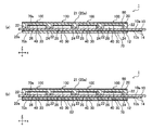
まず、本発明の第1の実施形態に係る荷重分布検出装置1について説明する。図1(a)は、荷重分布検出装置1の平面図であり、同図(b)は、荷重分布検出装置1の正面図である。また、図2(a)は、荷重分布検出装置1の底面図であり、同図(b)は、図1(a)のA−A線断面図である。
<First Embodiment>
First, the load distribution detection apparatus 1 according to the first embodiment of the present invention will be described. FIG. 1A is a plan view of the load distribution detection device 1, and FIG. 1B is a front view of the load distribution detection device 1. Moreover, Fig.2 (a) is a bottom view of the load distribution detection apparatus 1, The same figure (b) is the sectional view on the AA line of Fig.1 (a).

これらの図に示されるように、荷重分布検出装置1は、基板10と、基板10の一方の面に固定された弾性部材20と、基板10の弾性部材20の反対側の面に設けられた複数の固定電極30と、弾性部材20の基板10側の面に設けられた複数の可動電極40と、弾性部材20の基板10の反対側の面に設けられたシールド電極50と、基板10に接続された制御装置60と、を備えている。   As shown in these drawings, the load distribution detecting device 1 is provided on the substrate 10, the elastic member 20 fixed to one surface of the substrate 10, and the surface of the substrate 10 opposite to the elastic member 20. A plurality of fixed electrodes 30, a plurality of movable electrodes 40 provided on the surface of the elastic member 20 on the substrate 10 side, a shield electrode 50 provided on the surface of the elastic member 20 on the opposite side of the substrate 10, and the substrate 10 And a connected control device 60.

なお、以下の説明では、基板10の面方向をx方向およびy方向とし、基板10の面に直交する方向をz方向とする。また、z方向を垂直方向とし、基板10の上面10aに弾性部材20が固定されているものとして説明するが、荷重分布検出装置1の姿勢がこの状態に限定されないことは言うまでもない。また、図では、理解を容易にするために各部の厚みを誇張して記載している部分があることに留意されたい。   In the following description, the surface direction of the substrate 10 is the x direction and the y direction, and the direction orthogonal to the surface of the substrate 10 is the z direction. In addition, although the z direction is assumed to be a vertical direction and the elastic member 20 is fixed to the upper surface 10a of the substrate 10, the posture of the load distribution detection device 1 is not limited to this state. Also, in the drawings, it should be noted that there are portions where the thickness of each portion is exaggerated for easy understanding.

基板10は、略シート状(平板状)の部材であり、例えばポリイミドやポリエチレンテレフタレート(PET)等の樹脂フィルムから構成されている。図1(a)および(b)に示されるように、基板10の上面10aには、例えば接着剤等によって弾性部材20が固定されている。また、図2(a)に示されるように、基板10の底面10bには、x方向を長手方向とする略長方形状の4つのx方向帯状電極12が形成されており、詳細は後述するが、このx方向帯状電極12の一部が固定電極30となっている。   The substrate 10 is a substantially sheet-like (flat plate) member, and is made of, for example, a resin film such as polyimide or polyethylene terephthalate (PET). As shown in FIGS. 1A and 1B, an elastic member 20 is fixed to the upper surface 10a of the substrate 10 by, for example, an adhesive. Further, as shown in FIG. 2A, on the bottom surface 10b of the substrate 10, four substantially rectangular strip electrodes 12 having a substantially rectangular shape with the x direction as the longitudinal direction are formed. Details will be described later. A part of the x-direction strip electrode 12 is a fixed electrode 30.

本実施形態では、固定電極30(x方向帯状電極12)を基板10の底面に形成することで、基板10を固定電極30と可動電極40の間に配置される絶縁部材として兼用するようにしている。このようにすることで、荷重分布検出装置1を簡素且つ安価に構成することが可能になると共に、荷重分布検出装置1の厚み(z方向寸法)をより薄くすることが可能となっている。   In the present embodiment, the fixed electrode 30 (x-direction band-like electrode 12) is formed on the bottom surface of the substrate 10 so that the substrate 10 is also used as an insulating member disposed between the fixed electrode 30 and the movable electrode 40. Yes. By doing in this way, while being able to comprise the load distribution detection apparatus 1 simply and cheaply, it is possible to make the thickness (z direction dimension) of the load distribution detection apparatus 1 thinner.

基板10の底面10bにはまた、固定電極30および可動電極40と制御装置60を電気的に接続する複数の配線14が設けられている。なお、可動電極40は、基板10の上面10aに設けられた接続電極16および基板10を貫通するスルーホール18を介して配線14に接続されている。x方向帯状電極12(固定電極30)、配線14および接続電極16等は、例えばスクリーン印刷法やスパッタリング等、既知の手法により形成することができる。   A plurality of wirings 14 that electrically connect the fixed electrode 30 and the movable electrode 40 to the control device 60 are also provided on the bottom surface 10 b of the substrate 10. The movable electrode 40 is connected to the wiring 14 through a connection electrode 16 provided on the upper surface 10 a of the substrate 10 and a through hole 18 penetrating the substrate 10. The x-direction strip electrode 12 (fixed electrode 30), the wiring 14, the connection electrode 16, and the like can be formed by a known method such as screen printing or sputtering.

弾性部材20は、平面視が略矩形状の略シート状の部材であり、例えば各種絶縁ゴム等、絶縁性を有し且つ弾性変形可能な弾性材料から構成されている。弾性部材20は、基板10の上面10aに沿って配置され、主にz方向の荷重を受けて変形するように構成されている。そして、弾性部材20の上面20aは、検出する荷重を受ける受力面21となっている。すなわち、本実施形態ではx−y平面が検出面であり、荷重分布検出装置1はx−y平面内におけるz方向の荷重の分布を検出するように構成されている。   The elastic member 20 is a substantially sheet-like member having a substantially rectangular shape in plan view, and is made of an elastic material having an insulating property and elastically deformable, such as various insulating rubbers. The elastic member 20 is disposed along the upper surface 10a of the substrate 10 and is configured to be deformed mainly by receiving a load in the z direction. The upper surface 20a of the elastic member 20 is a force receiving surface 21 that receives a load to be detected. That is, in the present embodiment, the xy plane is a detection surface, and the load distribution detection device 1 is configured to detect a load distribution in the z direction in the xy plane.

図3(a)は、弾性部材20の平面図であり、同図(b)は、弾性部材20の底面図である。また、同図(c)は、同図(a)のB−B線断面図であり、同図(d)は、同図(a)のC−C線断面図である。これらの図に示されるように、弾性部材20は、受力面21である上面20aが略平滑面状に構成されている。そして、弾性部材20の底面20bには、基板10側に向けて突出した略格子状の凸部22、および凸部22の間で略矩形状に窪んだ凹部24が形成されている。   FIG. 3A is a plan view of the elastic member 20, and FIG. 3B is a bottom view of the elastic member 20. FIG. 3C is a cross-sectional view taken along the line BB in FIG. 1A, and FIG. 4D is a cross-sectional view taken along the line CC in FIG. As shown in these drawings, the elastic member 20 has a top surface 20a which is a force receiving surface 21 configured in a substantially smooth surface. The bottom surface 20b of the elastic member 20 is formed with a substantially lattice-shaped convex portion 22 protruding toward the substrate 10 and a concave portion 24 recessed in a substantially rectangular shape between the convex portions 22.

弾性部材20の上面10aには、略全面にわたってシールド電極50が形成されている。また、弾性部材20の底面20bには、y方向を長手方向とする略長方形状の4つのy方向帯状電極26が形成されている。このy方向帯状電極26は、凸部22および凹部24に跨って連続するように形成されており、一端部(図2(b)における上端部)において基板10の上面10aの接続電極16と接続するようになっている。そして、詳細は後述するが、y方向帯状電極26において凹部24に位置する部分が可動電極40となっている。   On the upper surface 10a of the elastic member 20, a shield electrode 50 is formed over substantially the entire surface. Further, on the bottom surface 20 b of the elastic member 20, four substantially rectangular y-direction belt-like electrodes 26 with the y direction as the longitudinal direction are formed. The y-direction band-like electrode 26 is formed so as to extend over the convex portion 22 and the concave portion 24, and is connected to the connection electrode 16 on the upper surface 10a of the substrate 10 at one end portion (the upper end portion in FIG. 2B). It is supposed to be. As will be described in detail later, the portion of the y-direction band electrode 26 located in the recess 24 is a movable electrode 40.

本実施形態ではシールド電極50およびy方向帯状電極26(可動電極40)を、例えばスクリーン印刷法やステンシル印刷法等の既知の手法により弾性部材20に塗布した導電性インクから構成している。このようにすることで、簡素且つ安価な構成でありながらも、弾性部材20の変形の自由度が損なわれないようにすることができるため、検出精度を向上させることができる。なお、シールド電極50およびy方向帯状電極26(可動電極40)は、導電性のフィラーを混入した導電性ゴムや導電性樹脂等を弾性部材20にインサート成形することにより構成されるものであってもよい。また、適宜の材料から構成されたシールド電極50およびy方向帯状電極26(可動電極40)を適宜の接着剤等で弾性部材に貼り付けるようにしてもよい。   In this embodiment, the shield electrode 50 and the y-direction band electrode 26 (movable electrode 40) are made of conductive ink applied to the elastic member 20 by a known method such as a screen printing method or a stencil printing method. By doing in this way, although it is a simple and cheap structure, since the freedom degree of a deformation | transformation of the elastic member 20 can be prevented from being impaired, detection accuracy can be improved. The shield electrode 50 and the y-direction band electrode 26 (movable electrode 40) are configured by insert-molding a conductive rubber, a conductive resin, or the like mixed with a conductive filler into the elastic member 20. Also good. Alternatively, the shield electrode 50 and the y-direction band electrode 26 (movable electrode 40) made of an appropriate material may be attached to the elastic member with an appropriate adhesive or the like.

図1および図2に戻って、固定電極30は、上述のようにx方向帯状電極12の一部であり、4つのx方向帯状電極12のそれぞれに4つずつ設けられている。すなわち、固定電極30は、基板10の底面10bに沿って、すなわち検出面であるx−y平面に沿ってマトリクス状に配列され、x方向に隣接するもの同士が電気的に接続されている。また、固定電極30は、配線14を介してx方向帯状電極12ごとに制御装置60に接続されている。すなわち、x方向に隣接する4つの固定電極30は、互いに電気的に接続された状態でまとめて制御装置60に接続されるようになっている。   Returning to FIGS. 1 and 2, the fixed electrode 30 is a part of the x-direction strip electrode 12 as described above, and four fixed electrodes 30 are provided on each of the four x-direction strip electrodes 12. That is, the fixed electrodes 30 are arranged in a matrix along the bottom surface 10b of the substrate 10, that is, along the xy plane that is a detection surface, and those adjacent in the x direction are electrically connected. In addition, the fixed electrode 30 is connected to the control device 60 for each x-direction strip electrode 12 via the wiring 14. That is, the four fixed electrodes 30 adjacent in the x direction are collectively connected to the control device 60 while being electrically connected to each other.

同様に、可動電極40は、上述のようにy方向帯状電極26の一部であり、4つのy方向帯状電極26のそれぞれに4つずつ設けられている。すなわち、可動電極40は、検出面であるx−y平面に沿ってマトリクス状に配列され、y方向に隣接するもの同士が電気的に接続されている。また、可動電極40は、配線14を介してy方向帯状電極26ごとに制御装置60に接続され、y方向に隣接する4つの可動電極40が互いに電気的に接続された状態でまとめて制御装置60に接続されるようになっている。   Similarly, the movable electrode 40 is a part of the y-direction band electrode 26 as described above, and four movable electrodes 40 are provided on each of the four y-direction band electrodes 26. That is, the movable electrodes 40 are arranged in a matrix along the xy plane which is a detection surface, and those adjacent in the y direction are electrically connected. In addition, the movable electrode 40 is connected to the control device 60 for each of the y-direction belt-like electrodes 26 via the wiring 14, and the four movable electrodes 40 adjacent to each other in the y direction are collectively connected to the control device. 60 is connected.

より具体的には、固定電極30は、図1(a)に示されるように、x方向帯状電極12においてy方向帯状電極26と交差する部分となっている。また、可動電極40は、y方向帯状電極26においてx方向帯状電極12と交差する部分となっている。従って、固定電極30および可動電極40は、互いに対向するようになっている。そして、本実施形態では、x方向帯状電極12およびy方向帯状電極26が互いに略直交するように構成しているため、固定電極30および可動電極40の形状は、いずれも矩形状となっている。   More specifically, as shown in FIG. 1A, the fixed electrode 30 is a portion that intersects the y-direction band electrode 26 in the x-direction band electrode 12. The movable electrode 40 is a portion that intersects the x-direction band electrode 12 in the y-direction band electrode 26. Accordingly, the fixed electrode 30 and the movable electrode 40 are opposed to each other. In the present embodiment, since the x-direction band electrode 12 and the y-direction band electrode 26 are configured to be substantially orthogonal to each other, the shapes of the fixed electrode 30 and the movable electrode 40 are both rectangular. .

また、本実施形態では、弾性部材20の凹部24を、x方向帯状電極12およびy方向帯状電極26の交差部分に配置することで、上述のように可動電極40が凹部24に配置されるようにし、固定電極30および可動電極40が所定の間隔を空けた状態で互いに対向するようにしている。これにより、受力面21に法線方向(すなわち、z方向)の荷重を受けて弾性部材20が変形した場合に、可動電極40が移動(変位)して固定電極30と可動電極40の間の距離が変化し、両者の間の静電容量が変化することとなる。従って、この静電容量の変化を検出することで、受力面21に受けた荷重を検出することができる。   In the present embodiment, the concave portion 24 of the elastic member 20 is disposed at the intersection of the x-direction strip electrode 12 and the y-direction strip electrode 26 so that the movable electrode 40 is disposed in the concave portion 24 as described above. The fixed electrode 30 and the movable electrode 40 are opposed to each other with a predetermined distance therebetween. As a result, when the elastic member 20 is deformed by receiving a load in the normal direction (that is, the z direction) on the force receiving surface 21, the movable electrode 40 moves (displaces) to move between the fixed electrode 30 and the movable electrode 40. The distance between the two changes, and the capacitance between the two changes. Therefore, the load received on the force receiving surface 21 can be detected by detecting the change in capacitance.

すなわち、互いに対向する一対の固定電極30および可動電極40は、静電容量の変化に基づいて荷重を検出するための1つの検出要素100(すなわち、静電容量検出部)を構成している。そして、複数の検出要素100における静電容量変化を検出することにより、受力面21に作用する荷重の位置および大きさ、すなわち検出面内(x−y平面内)における荷重の分布を検出することができる。具体的には、静電容量が変化した検出要素100を構成する固定電極30および可動電極40が、それぞれいずれのx方向帯状電極12およびy方向帯状電極26に属しているかに基づいて荷重の位置を検出することが可能であり、静電容量の変化量に基づいて荷重の大きさを検出することが可能である。   That is, the pair of fixed electrode 30 and movable electrode 40 facing each other constitute one detection element 100 (that is, a capacitance detection unit) for detecting a load based on a change in capacitance. Then, by detecting capacitance changes in the plurality of detection elements 100, the position and magnitude of the load acting on the force receiving surface 21, that is, the load distribution in the detection plane (in the xy plane) is detected. be able to. Specifically, the position of the load is determined based on which of the x-direction band electrode 12 and the y-direction band electrode 26 the fixed electrode 30 and the movable electrode 40 constituting the detection element 100 whose capacitance has changed. And the magnitude of the load can be detected based on the amount of change in capacitance.

なお、本実施形態では、x方向帯状電極12およびy方向帯状電極26を4つずつ設けることによって16個の検出要素100を備えているが、検出要素100の数がこれに限定されないことは言うまでもない。すなわち、検出要素100の数を調整することで、適宜の分解能に設定することができる。   In the present embodiment, 16 detection elements 100 are provided by providing four x-direction strip electrodes 12 and four y-direction strip electrodes 26, but it goes without saying that the number of detection elements 100 is not limited to this. Yes. That is, by adjusting the number of detection elements 100, an appropriate resolution can be set.

シールド電極50は、上述のように受力面21である弾性部材20の上面20aの全面にわたって形成されており、図示を省略した配線を介して接地された接地電極となっている。本実施形態では、このように上面20aにシールド電極50を設けることにより、検出要素100(固定電極30および可動電極40)を荷重が加えられる受力面21側から電気的に遮蔽するようにしている。   The shield electrode 50 is formed over the entire upper surface 20a of the elastic member 20 that is the force receiving surface 21 as described above, and serves as a ground electrode that is grounded via a wiring (not shown). In this embodiment, by providing the shield electrode 50 on the upper surface 20a in this manner, the detection element 100 (the fixed electrode 30 and the movable electrode 40) is electrically shielded from the force receiving surface 21 side to which a load is applied. Yes.

これにより、本実施形態では、荷重を加える外部の物体等に帯電した静電気等によるノイズをカットすると共に、荷重を加える外部の物体の材質によらず荷重を検出する、すなわち、人体の肌や金属等が直接受力面に接触する場合であっても高精度に荷重を検出することが可能となっている。特に、本実施形態では、上述のように導電性インクからシールド電極50を構成しているため、複雑な構造を採用することなく、検出要素100を電気的に遮蔽することが可能となっている。   Thereby, in the present embodiment, noise due to static electricity charged on an external object or the like to which a load is applied is cut, and the load is detected regardless of the material of the external object to which the load is applied, that is, the human skin or metal It is possible to detect the load with high accuracy even when the power contacts the force receiving surface directly. In particular, in this embodiment, since the shield electrode 50 is made of conductive ink as described above, the detection element 100 can be electrically shielded without adopting a complicated structure. .

なお、シールド電極50は、例えばメッシュ状や簾状等に形成されるものであってもよい。また、シールド電極50の上(外側)に適宜のコーティング層や弾性変形可能なシート状の絶縁部材等を配置し、その上面を受力面21とするようにしてもよい。すなわち、シールド電極50は、荷重を加える外部の物体と直接接触しないように配置されるものであってもよい。   The shield electrode 50 may be formed, for example, in a mesh shape or a hook shape. Further, an appropriate coating layer, an elastically deformable sheet-like insulating member, or the like may be disposed on the shield electrode 50 (outside), and the upper surface thereof may be used as the force receiving surface 21. That is, the shield electrode 50 may be disposed so as not to directly contact an external object to which a load is applied.

制御装置60は、x方向帯状電極12およびy方向帯状電極26に接続されて、各検出要素100における静電容量の変化を検出し、これに基づいて荷重分布を導出するものである。本実施形態の制御装置60は、各検出要素100における静電容量の変化を検出する静電容量検出処理手段62と、検出した静電容量変化に基づく演算処理を実行して各検出要素100における受力面21の法線方向(z方向)の荷重を導出する力学量換算処理手段64と、を備えている。   The control device 60 is connected to the x-direction strip electrode 12 and the y-direction strip electrode 26, detects a change in capacitance in each detection element 100, and derives a load distribution based on the change. The control device 60 of the present embodiment executes capacitance calculation processing means 62 that detects a change in capacitance in each detection element 100 and arithmetic processing based on the detected change in capacitance, and performs a detection process in each detection element 100. And a mechanical quantity conversion processing means 64 for deriving a load in the normal direction (z direction) of the force receiving surface 21.

静電容量検出処理手段62による静電容量変化の検出は、自己容量(Self Capacitance)方式および相互容量(Mutual Capacitance)方式のいずれを採用してもよいし、その他の既知の方式を採用するようにしてもよい。すなわち、荷重分布検出装置1の用途等に応じて適宜の方式を採用するようにすればよい。また、各検出要素100における静電容量変化からの荷重の導出方法は、既知のいずれかの手法を採用すればよい。   The detection of the change in capacitance by the capacitance detection processing means 62 may employ either a self-capacitance method or a mutual capacitance method, or other known methods. It may be. That is, an appropriate method may be adopted according to the use of the load distribution detection device 1 or the like. In addition, any known method may be adopted as a method for deriving the load from the capacitance change in each detection element 100.

制御装置60はまた、必要に応じて、各検出要素100における静電容量変化もしくは導出した荷重分布を記憶する、または外部のPC等の機器に出力する。なお、制御装置60は、荷重分布検出装置1とは別体に設けられるものであってもよい。すなわち、荷重分布検出装置1は、外部のPC等の演算処理装置によって制御されるものであってもよい。   The control device 60 also stores the capacitance change or the derived load distribution in each detection element 100 as necessary, or outputs it to an external device such as a PC. The control device 60 may be provided separately from the load distribution detection device 1. That is, the load distribution detection device 1 may be controlled by an arithmetic processing device such as an external PC.

次に、本実施形態の荷重分布検出装置1の作用について説明する。図4(a)および(b)は、荷重分布検出装置1の受力面21にz方向の荷重Fzが作用した状態を示した図であり、図1(a)のA−A線断面図である。上述のように、本実施形態の荷重分布検出装置1は、弾性部材20の受力面21に加わるz方向(法線方向)の荷重Fzの大きさを位置ごとに検出することによって荷重Fzの分布を検出する。   Next, the operation of the load distribution detection device 1 of this embodiment will be described. 4A and 4B are views showing a state in which a load Fz in the z direction is applied to the force receiving surface 21 of the load distribution detection device 1, and is a cross-sectional view taken along the line AA in FIG. It is. As described above, the load distribution detection device 1 according to this embodiment detects the magnitude of the load Fz in the z direction (normal direction) applied to the force receiving surface 21 of the elastic member 20 for each position, thereby detecting the load Fz. Detect distribution.

図4(a)に示されるように、受力面21の各部にそれぞれ異なる荷重Fzが加わった場合、弾性部材20は荷重Fzの大きさに応じて弾性変形し、これにより、各検出要素100では、荷重Fzの大きさに応じて可動電極40が固定電極30に近接することとなる。また、荷重Fzが解除される際には、弾性変形の復元力によって弾性部材20は元の状態に戻ろうとするため、可動電極40は固定電極30から離隔していくこととなる。   As shown in FIG. 4A, when a different load Fz is applied to each part of the force receiving surface 21, the elastic member 20 is elastically deformed according to the magnitude of the load Fz. Then, the movable electrode 40 comes close to the fixed electrode 30 according to the magnitude of the load Fz. Further, when the load Fz is released, the elastic member 20 tries to return to the original state by the restoring force of elastic deformation, so that the movable electrode 40 is separated from the fixed electrode 30.

すなわち、各検出要素100では、作用する荷重Fzの大きさに応じて静電容量が変化することとなるため、これに基づいて、荷重Fzの分布を求めることができる。このとき、例えば複数の検出要素100における静電容量の変化量を補間するようにすれば、荷重分布検出の分解能を検出要素100の数以上に高めることができる。   That is, in each detection element 100, since an electrostatic capacitance changes according to the magnitude | size of the load Fz which acts, based on this, distribution of the load Fz can be calculated | required. At this time, for example, if the amount of change in capacitance in the plurality of detection elements 100 is interpolated, the resolution of load distribution detection can be increased to the number of detection elements 100 or more.

また、図4(b)に示されるように、荷重Fzが局所的に加わった場合、いずれの検出要素100の静電容量が変化したかによって、荷重Fzが加わった位置を特定することができる。すなわち、荷重分布検出装置1を、入力位置を検出する入力装置として使用することができる。なお、この場合においても、複数の検出要素100における静電容量の変化量を補間することによって荷重Fzの中心位置を求めるようにすれば、入力位置検出の分解能を高めることができる。   Further, as shown in FIG. 4B, when the load Fz is locally applied, the position where the load Fz is applied can be specified depending on which capacitance of the detection element 100 has changed. . That is, the load distribution detection device 1 can be used as an input device that detects an input position. Even in this case, if the center position of the load Fz is obtained by interpolating the amount of change in capacitance in the plurality of detection elements 100, the resolution of input position detection can be increased.

次に、本実施形態の荷重分布検出装置1のその他の形態について説明する。図5〜8は、荷重分布検出装置1のその他の形態を示した図である。   Next, the other form of the load distribution detection apparatus 1 of this embodiment is demonstrated. 5-8 is the figure which showed the other form of the load distribution detection apparatus 1. FIG.

図5(a)および(b)は、弾性部材20の凸部22を円柱状に構成した場合の一例を示しており、同図(a)は弾性部材20の底面図、同図(b)は同図(a)のB−B線断面図である。凸部22の形状は特に限定されるものではなく、このように、例えば円柱状に構成した凸部22を複数設けるようにしてもよい。   FIGS. 5A and 5B show an example in which the convex portion 22 of the elastic member 20 is formed in a columnar shape. FIG. 5A is a bottom view of the elastic member 20 and FIG. These are sectional views taken along the line BB of FIG. The shape of the convex portion 22 is not particularly limited. Thus, for example, a plurality of convex portions 22 configured in a columnar shape may be provided.

凸部22の形状および配置を適宜に設定することにより、弾性部材20の強度、および受力面21が荷重を受けた際の弾性部材20の弾性変形の程度を調整することができる。また、凸部22の形状および配置によって基板10と弾性部材20の間における気体の流動を調整することで、弾性部材20が弾性変形する際の当該気体の圧縮・膨張によって弾性部材の弾性変形が阻害されないようにすることができる。   By appropriately setting the shape and arrangement of the convex portions 22, the strength of the elastic member 20 and the degree of elastic deformation of the elastic member 20 when the force receiving surface 21 receives a load can be adjusted. Further, by adjusting the gas flow between the substrate 10 and the elastic member 20 according to the shape and arrangement of the protrusions 22, the elastic member 20 is elastically deformed by the compression and expansion of the gas when the elastic member 20 is elastically deformed. It can be prevented from being inhibited.

なお、凸部22は、壁状に構成されるものであってもよいし、柱状に構成されるものであってもよい。また、凸部22は、円錐状、角錐状、円錐台状、角錐台状、または半球状等に構成されるものであってもよいし、壁状に構成した凸部22に適宜の通気孔を設けるようにしてもよい。また、弾性部材20は、荷重を受けた場合に、凸部22および凸部22以外の部分が共に弾性変形するように構成してもよいし、凸部22のみ、または凸部22以外の部分のみが弾性変形するように構成してもよい。   In addition, the convex part 22 may be comprised by wall shape, and may be comprised by column shape. Further, the convex portion 22 may be configured in a conical shape, a pyramid shape, a truncated cone shape, a truncated pyramid shape, a hemispherical shape, or the like, or an appropriate air hole in the convex portion 22 configured in a wall shape. May be provided. Further, the elastic member 20 may be configured such that, when receiving a load, both the convex portion 22 and a portion other than the convex portion 22 are elastically deformed, or only the convex portion 22 or a portion other than the convex portion 22. Only the elastic deformation may be adopted.

また、図3(a)〜(d)ならびに図5(a)および(b)に示す例では、凸部22を各検出要素100の間(各検出要素100の周囲)に設けるようにした例を示したが、検出要素100内に凸部22を設けるようにしてもよい。検出要素100内に凸部20を設けることにより、弾性部材20および装置全体の強度および耐久性をより高めることが可能となる。この場合、図示は省略するが、例えば可動電極40の中央部に孔部を設け、この孔部に凸部22を設けるようにしてもよい。また、検出要素100内の凸部22に可動電極40を設けるようにしてもよい。   Further, in the examples shown in FIGS. 3A to 3D and FIGS. 5A and 5B, the convex portions 22 are provided between the detection elements 100 (around the detection elements 100). However, the convex portion 22 may be provided in the detection element 100. By providing the convex portion 20 in the detection element 100, it is possible to further increase the strength and durability of the elastic member 20 and the entire apparatus. In this case, although not shown, for example, a hole may be provided in the center of the movable electrode 40 and the protrusion 22 may be provided in the hole. Further, the movable electrode 40 may be provided on the convex portion 22 in the detection element 100.

図5(c)は、検出要素100内の凸部22に可動電極40を設けるようにした例を示した概略断面図である。この例では、略円錐状に構成した山型凸部22aを検出要素100内に設け、この山型凸部22aにおける基板10側の面に可動電極40を設けている。この場合、同図(c)に示されるように、荷重Fzによって山型凸部22aが潰れるように変形するため、荷重Fzの大きさに応じて可動電極40と基板10の上面10aとの接触部分の面積が変化することとなる。そして、主にこの接触部分の面積の変化に応じて、検出要素100における静電容量が変化することとなる。   FIG. 5C is a schematic cross-sectional view showing an example in which the movable electrode 40 is provided on the convex portion 22 in the detection element 100. In this example, a mountain-shaped convex portion 22a configured in a substantially conical shape is provided in the detection element 100, and the movable electrode 40 is provided on the surface of the mountain-shaped convex portion 22a on the substrate 10 side. In this case, as shown in FIG. 6C, the mountain-shaped convex portion 22a is deformed so as to be crushed by the load Fz. The area of the part will change. And the electrostatic capacitance in the detection element 100 will change mainly according to the change of the area of this contact part.

このように、検出要素100内の山型凸部22aに可動電極40を設けることで、弾性部材20および装置全体の強度および耐久性を高めるだけではなく、検出要素100における静電容量の変化をより安定させることが可能となる。さらに、山型凸部22aの傾斜面22a1の形状(例えば、傾斜角度や曲面形状等)を調整することで、静電容量の変化量および変化の態様(例えば、直線的な変化や二次曲線的な変化等)を適宜に設定することが可能となるため、検出精度を向上させることができる。   Thus, by providing the movable electrode 40 on the mountain-shaped convex portion 22a in the detection element 100, not only the strength and durability of the elastic member 20 and the entire apparatus are increased, but also the capacitance of the detection element 100 is changed. It becomes possible to make it more stable. Further, by adjusting the shape of the inclined surface 22a1 (for example, the inclination angle or curved surface shape) of the mountain-shaped convex portion 22a, the amount of change in capacitance and the mode of change (for example, linear change or quadratic curve) Therefore, the detection accuracy can be improved.

なお、山型凸部22aの形状は、略円錐状に限定される物ではなく、例えば角錐状や半球状等であってもよいし、傾斜面22a1の代わりに例えば階段状に高さが変化する部分を有する形状であってもよい。すなわち、山型凸部22aの形状は、荷重に押圧されて潰れることによって基板10の上面10aとの接触面積が増加していくように、検出要素100の略中央から外側に向けて漸次基板10の上面10aから遠ざかる部分を有する形状であればよい。また、弾性部材20に設けた山型凸部22aに可動電極40を設けるのではなく、可動電極40を弾性変形可能な導電性ゴム等から構成して凹凸形状を設けることにより、可動電極40自体が山型凸部22aを備えるように構成してもよい。   The shape of the mountain-shaped convex portion 22a is not limited to a substantially conical shape, and may be, for example, a pyramid shape or a hemispherical shape, and the height changes, for example, in a step shape instead of the inclined surface 22a1. The shape which has the part to do may be sufficient. That is, the shape of the mountain-shaped convex portion 22a is such that the contact area with the upper surface 10a of the substrate 10 increases by being pressed and crushed by the load, gradually from the substantially center of the detection element 100 toward the outside. Any shape having a portion away from the upper surface 10a may be used. Further, instead of providing the movable electrode 40 on the mountain-shaped convex portion 22a provided on the elastic member 20, the movable electrode 40 itself is formed by forming the movable electrode 40 from an elastically deformable conductive rubber or the like and providing an uneven shape. May be provided with a mountain-shaped convex portion 22a.

図6(a)および(b)は、弾性部材20の受力面21に凹凸形状を設けた場合の一例を示しており、同図(a)は弾性部材20の平面図、同図(b)は同図(a)のB−B線断面図である。弾性部材20の受力面21は、平滑面状に構成されるものに限定されるものではなく、このように、例えば円柱状の突起部21aを受力面21に複数設けるようにしてもよい。このように、受力面21に適宜の凹凸形状を設けることで、荷重を受けた際の弾性部材20の弾性変形状態をより適切な状態に設定することができる。   6 (a) and 6 (b) show an example in which an uneven shape is provided on the force receiving surface 21 of the elastic member 20. FIG. 6 (a) is a plan view of the elastic member 20, and FIG. ) Is a cross-sectional view taken along line BB in FIG. The force receiving surface 21 of the elastic member 20 is not limited to the one configured to be a smooth surface. Thus, for example, a plurality of columnar protrusions 21 a may be provided on the force receiving surface 21. . Thus, by providing an appropriate uneven shape on the force receiving surface 21, the elastic deformation state of the elastic member 20 when receiving a load can be set to a more appropriate state.

なお、突起部21aの形状は特に限定されるものではなく、例えば半球状等、その他の形状であってもよい。また、図6(a)および(b)では、各検出要素100に対応する位置に突起部21aを設けるようにした例を示したが、突起部21aの配置はこれに限定されるものではなく、例えば各検出要素100の間にも突起部21aを配置する等、その他の配置であってもよい。また、突起部21aの形状や大きさを異ならせるようにしてもよいし、突起部21aに代えて、または突起部21aと共に窪み部を設けるようにしてもよい。   The shape of the protruding portion 21a is not particularly limited, and may be other shapes such as a hemispherical shape. 6A and 6B show an example in which the protrusion 21a is provided at a position corresponding to each detection element 100, the arrangement of the protrusion 21a is not limited to this. For example, other arrangements such as arranging the protruding portions 21a between the detection elements 100 may be possible. Further, the shape and size of the protrusion 21a may be varied, or a recess may be provided in place of the protrusion 21a or together with the protrusion 21a.

図7(a)および(b)は、基板10の底面10b側に補助弾性部材70を設けた場合の例を示しており、図1(a)のA−A線断面図である。この例では、基板10の底面10b側、すなわち弾性部材20の反対側に、略シート状の補助弾性部材70を配置している。そして、補助弾性部材70は、例えば各種絶縁ゴム等、絶縁性を有し且つ弾性変形可能な弾性材料から構成され、接着材等によって基板10の底面10bに固定されている。   FIGS. 7A and 7B show an example in which the auxiliary elastic member 70 is provided on the bottom surface 10b side of the substrate 10, and is a cross-sectional view taken along the line AA in FIG. In this example, a substantially sheet-like auxiliary elastic member 70 is disposed on the bottom surface 10 b side of the substrate 10, that is, on the opposite side of the elastic member 20. The auxiliary elastic member 70 is made of an elastic material having an insulating property and elastically deformable, such as various insulating rubbers, and is fixed to the bottom surface 10b of the substrate 10 with an adhesive or the like.

このように、補助弾性部材70を設けることにより、例えば基板10をシリコンラバーフィルム等の比較的柔らかい材質から構成したような場合においても、荷重分布検出装置1の強度および剛性を適宜に高めることが可能となる。すなわち、基板10の材質選定に併せて適宜に補助弾性部材70を設けることにより、荷重分布検出装置1の強度および剛性を用途や使用環境等に応じて適切に設定することができるため、荷重分布検出装置1の汎用性を高めることができる。また、補助弾性部材70で固定電極30を覆うことにより、固定電極30を適切に保護することが可能となる。   Thus, by providing the auxiliary elastic member 70, the strength and rigidity of the load distribution detection device 1 can be appropriately increased even when the substrate 10 is made of a relatively soft material such as a silicon rubber film. It becomes possible. That is, since the auxiliary elastic member 70 is appropriately provided in conjunction with the material selection of the substrate 10, the strength and rigidity of the load distribution detection device 1 can be appropriately set according to the use and the use environment. The versatility of the detection apparatus 1 can be improved. Further, by covering the fixed electrode 30 with the auxiliary elastic member 70, the fixed electrode 30 can be appropriately protected.

なお、補助弾性部材70を設ける場合、固定電極30を基板10ではなく、補助弾性部材70に形成するようにしてもよく、さらに、固定電極30を補助弾性部材70の上面70aに塗布した導電性インクから構成するようにしてもよい。また、補助弾性部材70および基板10を、共に絶縁性ゴムから構成するようにしてもよく、この場合、荷重分布検出装置1をx−y平面内において伸縮可能に構成することができるため、荷重分布検出装置1の汎用性をさらに高めることが可能となる。   In the case where the auxiliary elastic member 70 is provided, the fixed electrode 30 may be formed not on the substrate 10 but on the auxiliary elastic member 70. Furthermore, the conductive material obtained by applying the fixed electrode 30 to the upper surface 70a of the auxiliary elastic member 70 may be used. You may make it comprise from ink. In addition, both the auxiliary elastic member 70 and the substrate 10 may be made of insulating rubber. In this case, the load distribution detection device 1 can be configured to be extendable and contractable in the xy plane. The versatility of the distribution detection apparatus 1 can be further enhanced.

図7(b)は、補助弾性部材70に補助シールド電極52を設けた場合の一例を示している。この例では、補助弾性部材70の底面70bの略全面にわたって補助シールド電極52を形成している。そして、補助シールド電極52は、補助弾性部材70の底面70bに塗布した導電性インクから構成され、図示を省略した配線を介して接地されている。このように補助シールド電極52を設けることにより、周囲の静電気等によるノイズをより効果的にカットすることが可能となるため、検出精度を高めると共に荷重分布検出装置1の汎用性を高めることができる。   FIG. 7B shows an example in which the auxiliary shield electrode 52 is provided on the auxiliary elastic member 70. In this example, the auxiliary shield electrode 52 is formed over substantially the entire bottom surface 70 b of the auxiliary elastic member 70. The auxiliary shield electrode 52 is made of conductive ink applied to the bottom surface 70b of the auxiliary elastic member 70, and is grounded via a wiring (not shown). By providing the auxiliary shield electrode 52 in this way, noise due to surrounding static electricity or the like can be more effectively cut, so that the detection accuracy can be improved and the versatility of the load distribution detection device 1 can be improved. .

なお、補助弾性部材70を複数層重ねて設けるようにしてもよく、さらにこの場合、固定電極30や補助シールド電極52、各種配線等を補助弾性部材70同士の間に配置するようにしてもよい。また、補助弾性部材70は、x−y平面内の寸法が弾性部材70のx−y平面内の寸法と異なるものであってもよく、例えば基板10に形成された配線14を覆うものであってもよい。また、補助シールド電極52は、例えばメッシュ状や簾状等に形成されるものであってもよい。また、スルーホール等を介して、シールド電極50と補助シールド電極52を電気的に短絡するようにしてもよい。   The auxiliary elastic member 70 may be provided in a plurality of layers. In this case, the fixed electrode 30, the auxiliary shield electrode 52, various wirings, and the like may be disposed between the auxiliary elastic members 70. . Further, the auxiliary elastic member 70 may have a dimension in the xy plane that is different from the dimension in the xy plane of the elastic member 70, and covers the wiring 14 formed on the substrate 10, for example. May be. Further, the auxiliary shield electrode 52 may be formed in, for example, a mesh shape or a hook shape. Further, the shield electrode 50 and the auxiliary shield electrode 52 may be electrically short-circuited through a through hole or the like.

図8(a)は、x方向帯状電極12のその他の形態の一例を示しており、同図(b)は、y方向帯状電極26のその他の形態の一例を示している。なお、同図(a)は基板10の底面図であり、同図(b)は弾性部材20の底面図である。固定電極30を含むx方向帯状電極12、および可動電極40を含むy方向帯状電極26の形状は、特に限定されるものではなく、例えばこのように、固定電極30および可動電極40を略円形状に構成すると共に、固定電極30および可動電極40とそれ以外の部分の幅を異ならせるようにしてもよい。   FIG. 8A shows an example of another form of the x-direction band electrode 12, and FIG. 8B shows an example of another form of the y-direction band electrode 26. 1A is a bottom view of the substrate 10 and FIG. 1B is a bottom view of the elastic member 20. The shapes of the x-direction strip electrode 12 including the fixed electrode 30 and the y-direction strip electrode 26 including the movable electrode 40 are not particularly limited. For example, the fixed electrode 30 and the movable electrode 40 are substantially circular as described above. In addition, the widths of the fixed electrode 30 and the movable electrode 40 and other portions may be different.

このように、x方向帯状電極12およびy方向帯状電極26の形状、ならびに固定電極30および可動電極40の形状を調整することで、弾性部材20が弾性変形した際の静電容量の変化量および変化の態様(例えば、直線的な変化や二次曲線的な変化等)を適宜に設定することが可能となるため、検出精度を高めることができる。   Thus, by adjusting the shapes of the x-direction strip electrode 12 and the y-direction strip electrode 26 and the shapes of the fixed electrode 30 and the movable electrode 40, the amount of change in capacitance when the elastic member 20 is elastically deformed and Since it is possible to appropriately set the change mode (for example, a linear change or a quadratic change), the detection accuracy can be increased.

なお、固定電極30および可動電極40の形状は、例えば多角形状や楕円形状等、その他の形状であってもよいことは言うまでもない。また、x方向帯状電極12およびy方向帯状電極26は、固定電極30同士および可動電極40同士を直線的に接続するのではなく、例えば凸部22等を迂回して接続するように構成されるものであってもよい。   Needless to say, the shapes of the fixed electrode 30 and the movable electrode 40 may be other shapes such as a polygonal shape and an elliptical shape. Further, the x-direction strip electrode 12 and the y-direction strip electrode 26 are configured not to linearly connect the fixed electrodes 30 and the movable electrodes 40 but to connect, for example, by bypassing the convex portion 22 and the like. It may be a thing.

また、固定電極30および可動電極40は、それぞれx方向帯状電極12およびy方向帯状電極26の一部として構成されるものに限定されるものではなく、例えばリード線等によって固定電極30同士および可動電極40同士を電気的に接続するようにしてもよい。すなわち、固定電極30は、x方向に隣接するもの同士が既知のいずれかの手法によって電気的に接続されるものであればよく、可動電極40は、y方向に隣接するもの同士が既知のいずれかの手法によって電気的に接続されるものであればよい。   Further, the fixed electrode 30 and the movable electrode 40 are not limited to those configured as a part of the x-direction band-shaped electrode 12 and the y-direction band-shaped electrode 26, respectively. The electrodes 40 may be electrically connected. That is, the fixed electrode 30 may be any electrode that is adjacent to the x direction by any known method, and the movable electrode 40 is any electrode that is adjacent to the y direction. What is necessary is just to be electrically connected by such a method.

<第2の実施形態>
次に、本発明の第2の実施形態に係る荷重分布検出装置2について説明する。本実施形態に係る荷重分布検出装置2は、受力面21の法線方向、すなわちz方向に作用する荷重の分布に加えて、受力面21の面方向、すなわちx−y平面内(検出面内)におけるいずれかの方向(x−y平面に平行な方向)に作用する荷重の分布を検出するように構成されている。なお、以下の説明においては、第1の実施形態の荷重分布検出装置1と同一の部分については同一の符号を付すと共にその説明を省略し、第1の実施形態と異なる部分について説明する。
<Second Embodiment>
Next, a load distribution detection apparatus 2 according to the second embodiment of the present invention will be described. The load distribution detection device 2 according to the present embodiment has a surface direction of the force receiving surface 21, that is, an xy plane (detection) in addition to the distribution of the load acting in the normal direction of the force receiving surface 21, that is, the z direction. It is configured to detect the distribution of loads acting in any direction (in the plane) (direction parallel to the xy plane). In the following description, the same parts as those of the load distribution detection device 1 of the first embodiment are denoted by the same reference numerals and the description thereof is omitted, and the parts different from the first embodiment will be described.

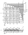
図9(a)は、荷重分布検出装置2の平面図であり、同図(b)は、荷重分布検出装置2の正面図である。また、図10(a)は、荷重分布検出装置2の底面図であり、同図(b)は、図9(a)のA−A線断面図である。   FIG. 9A is a plan view of the load distribution detection device 2, and FIG. 9B is a front view of the load distribution detection device 2. Moreover, Fig.10 (a) is a bottom view of the load distribution detection apparatus 2, and the same figure (b) is the sectional view on the AA line of Fig.9 (a).

これらの図に示されるように、本実施形態の荷重分布検出装置2は、互いに交差するように配置されるx方向帯状電極12およびy方向帯状電極26をそれぞれ8つ備えている。従って、x方向帯状電極12およびy方向帯状電極26は、互いに交差する部分をそれぞれ8箇所に有しており、x方向帯状電極12には8つの固定電極30が設けられると共に、y方向帯状電極26には8つの可動電極40が設けられている。そして、可動電極40は、x方向およびy方向に隣接する4つを一組として1つの凹部24内に配置されるようになっており、固定電極30は、所定の間隔を空けた状態で可動電極40にそれぞれ対向している。   As shown in these drawings, the load distribution detection device 2 of the present embodiment includes eight x-direction strip electrodes 12 and eight y-direction strip electrodes 26 arranged so as to cross each other. Accordingly, the x-direction strip electrode 12 and the y-direction strip electrode 26 each have eight portions that intersect each other. The x-direction strip electrode 12 is provided with eight fixed electrodes 30 and the y-direction strip electrode 12. Eight movable electrodes 40 are provided at 26. The movable electrode 40 is arranged in one recess 24 as a set of four adjacent in the x direction and the y direction, and the fixed electrode 30 is movable with a predetermined interval. The electrodes 40 are opposed to each other.

すなわち、本実施形態では、x方向およびy方向に隣接する4つの検出要素100から1つの2軸検出要素110を構成し、この2軸検出要素110によってz方向の荷重およびx−y平面内の荷重を検出することを可能としている。従って、本実施形態では、制御装置60の力学量換算処理手段64は、2軸検出要素110に含まれる4つの検出要素100における静電容量の変化量に基づく演算処理を実行することにより、受力面21の法線方向(z方向)の荷重の大きさに加えて、受力面21の面方向(x−y平面内のいずれかの方向)に作用する荷重の大きさおよび方向を導出する。   That is, in the present embodiment, one two-axis detection element 110 is configured from the four detection elements 100 adjacent to each other in the x direction and the y direction, and the load in the z direction and the xy plane by the two axis detection element 110. The load can be detected. Therefore, in the present embodiment, the mechanical quantity conversion processing unit 64 of the control device 60 receives the calculation amount based on the amount of change in capacitance in the four detection elements 100 included in the two-axis detection element 110. In addition to the magnitude of the load in the normal direction (z direction) of the force surface 21, the magnitude and direction of the load acting in the surface direction of the force receiving surface 21 (any direction in the xy plane) are derived. To do.

また、本実施形態では、弾性部材20の上面20a(受力面21)の2軸検出要素110に対応する位置に、突起部21aを設けることにより、x−y平面内の荷重を受けた場合に、モーメントによって突起部21aおよびその近傍が傾くように弾性部材20が変形するようにしている。   Moreover, in this embodiment, when the load in an xy plane is received by providing the projection part 21a in the position corresponding to the biaxial detection element 110 of the upper surface 20a (power receiving surface 21) of the elastic member 20. In addition, the elastic member 20 is deformed so that the protrusion 21a and the vicinity thereof are inclined by the moment.

図11(a)は、荷重分布検出装置2の受力面21にx−y平面内の荷重Fxy、およびz方向の荷重Fzが作用した状態を示した図であり、図9(a)のA−A線断面図である。図9に示されるように、受力面21に荷重Fxyが加わった場合、弾性部材20の突起部21aおよびその近傍は傾くように弾性変形し、2軸検出要素110に含まれる4つの検出要素100では固定電極30と可動電極40の間の距離がそれぞれ変化することとなる。すなわち、2軸検出要素110に含まれる4つの検出要素100の静電容量がそれぞれ変化することとなる。   FIG. 11A is a diagram showing a state in which the load Fxy in the xy plane and the load Fz in the z direction are applied to the force receiving surface 21 of the load distribution detection device 2, and FIG. It is AA sectional view. As shown in FIG. 9, when a load Fxy is applied to the force receiving surface 21, the protruding portion 21 a of the elastic member 20 and the vicinity thereof are elastically deformed so as to be inclined, and the four detection elements included in the biaxial detection element 110. At 100, the distance between the fixed electrode 30 and the movable electrode 40 changes. That is, the capacitances of the four detection elements 100 included in the two-axis detection element 110 change.

制御装置60の力学量換算処理手段64は、例えば2軸検出要素110においてx方向に隣接する2つの検出要素100における静電容量の変化量の差に基づいてx方向の荷重を導出し、y方向に隣接する2つの検出要素100における静電容量の変化量の差に基づいてy方向の荷重を導出する。そして、x方向荷重とy方向荷重をベクトル合成することにより、荷重Fxyの大きさおよび方向を導出する。これにより、2軸検出要素110ごとに荷重Fxyが検出されることとなるため、これに基づいて荷重Fxyの分布を求めることができる。   The mechanical quantity conversion processing means 64 of the control device 60 derives the load in the x direction based on the difference in the amount of change in capacitance between the two detection elements 100 adjacent in the x direction in the biaxial detection element 110, for example, y A load in the y direction is derived based on the difference in the amount of change in capacitance between two detection elements 100 adjacent in the direction. Then, the magnitude and direction of the load Fxy are derived by vector synthesis of the x-direction load and the y-direction load. Thereby, since the load Fxy is detected for every biaxial detection element 110, distribution of the load Fxy can be calculated | required based on this.

一方、受力面21に荷重Fzが加わった場合、弾性部材20の突起部21aおよびその近傍は基板10に近接するように変形し、受力面21に荷重Fxyおよび荷重Fzが複合的に作用する場合は、弾性部材20の突起部21aおよびその近傍は傾きつつ基板10に近接するように変形することとなる。   On the other hand, when the load Fz is applied to the force receiving surface 21, the protrusion 21 a of the elastic member 20 and its vicinity are deformed so as to be close to the substrate 10, and the load Fxy and the load Fz act on the force receiving surface 21 in a composite manner. In this case, the protrusion 21a of the elastic member 20 and the vicinity thereof are deformed so as to be close to the substrate 10 while being inclined.

従って、本実施形態では、制御装置60の力学量換算処理手段64は、2軸検出要素110に含まれる4つの検出要素100の静電容量の変化量の合計に基づいて荷重Fzの大きさを導出する。これにより、荷重Fxyの影響を排除し、2軸検出要素110ごとに荷重Fzのみを検出することが可能となるため、荷重Fzの分布を求めることができる。すなわち、本実施形態の荷重分布検出装置2によれば、受力面21に荷重Fxyおよび荷重Fzが複合的に作用する場合であっても、荷重Fxyの分布および荷重Fzの分布をそれぞれ独立して検出することができる。   Therefore, in the present embodiment, the mechanical quantity conversion processing means 64 of the control device 60 calculates the magnitude of the load Fz based on the total amount of change in capacitance of the four detection elements 100 included in the biaxial detection element 110. To derive. As a result, the influence of the load Fxy can be eliminated and only the load Fz can be detected for each of the two-axis detection elements 110, so that the distribution of the load Fz can be obtained. That is, according to the load distribution detection device 2 of the present embodiment, the distribution of the load Fxy and the distribution of the load Fz are independent from each other even when the load Fxy and the load Fz act on the force receiving surface 21 in a composite manner. Can be detected.

また、本実施形態では、固定電極30のx方向に隣接するもの同士を電気的に接続すると共に、可動電極40のy方向に隣接するもの同士を電気的に接続することにより、複数方向の荷重(荷重Fxyおよび荷重Fz)の分布を検出可能な構成でありながらも、各検出要素100における静電容量の変化を効率的に検出することを可能としている。すなわち、複数方向の荷重を検出可能な荷重検出装置を個別に複数配置した場合(例えば、上記特許文献1の背景技術に記載の技術)と比較して、装置全体をより簡素に構成することが可能になると共に、より高速に複数方向の荷重分布を検出することが可能となっている。   Further, in the present embodiment, the adjacent electrodes in the x direction of the fixed electrode 30 are electrically connected to each other, and the adjacent electrodes in the y direction of the movable electrode 40 are electrically connected to each other, so that loads in a plurality of directions are obtained. Although the configuration can detect the distribution of (load Fxy and load Fz), it is possible to efficiently detect a change in capacitance in each detection element 100. That is, the entire apparatus can be configured more simply as compared with a case where a plurality of load detection apparatuses capable of detecting loads in a plurality of directions are individually arranged (for example, the technique described in the background art of Patent Document 1). In addition to being possible, it is possible to detect load distributions in a plurality of directions at higher speeds.

なお、静電容量検出処理手段62による静電容量変化の検出は、第1の実施形態と同様に、自己容量方式および相互容量方式のいずれを採用することもできるし、その他の既知の方式を採用することも可能である。また、各検出要素100における静電容量変化からの荷重の導出方法は、上記方法以外にも既知のその他の手法を採用することができる。また、z方向の荷重の導出を省略し、x−y平面内の荷重の分布のみを検出するようにしてもよい。   In addition, the detection of the change in capacitance by the capacitance detection processing means 62 can adopt either the self-capacitance method or the mutual capacitance method, as in the first embodiment, and other known methods. It is also possible to adopt. In addition to the above method, other known methods can be adopted as a method for deriving the load from the capacitance change in each detection element 100. Alternatively, the derivation of the load in the z direction may be omitted, and only the load distribution in the xy plane may be detected.

また、突起部21aの形状は、円柱状に限定されるものではなく、例えば半球状や円錐状等、その他の適宜の形状を採用することができる。また、2軸検出要素110に対応する位置に複数の突起部21aを設けるようにしてもよいし、2軸検出要素110に対応する位置以外の部分に突起部21aを設けるようにしてもよい。また、第1の実施形態において示した各種構成を本実施形態の荷重分布検出装置2に適用してもよいことは言うまでもない。   Further, the shape of the protruding portion 21a is not limited to a cylindrical shape, and other appropriate shapes such as a hemispherical shape and a conical shape can be employed. In addition, a plurality of protrusions 21a may be provided at positions corresponding to the biaxial detection elements 110, or the protrusions 21a may be provided at portions other than the positions corresponding to the biaxial detection elements 110. Needless to say, the various configurations shown in the first embodiment may be applied to the load distribution detection device 2 of the present embodiment.

また、2軸検出要素110に含まれる検出要素100の数は、4つに限定されるものではなく、5つ以上であってもよい。すなわち、固定電極30および可動電極40の形状、配置および接続方向等に応じて、適宜の個数の検出要素100から2軸検出要素110を構成することができる。さらに、2軸検出要素110を3つの検出要素100から構成するようにしてもよい。この場合、本出願人に係る特許第4756097号に開示されるように、3つの検出要素100における静電容量変化量の重心位置を算出することにより、x−y平面内の荷重を導出することができる。なお、検出要素100が4つ以上の場合においても、各検出要素100における静電容量変化量の重心位置を算出することによってx−y平面内の荷重を導出可能であることは言うまでもない。   The number of detection elements 100 included in the biaxial detection element 110 is not limited to four, and may be five or more. That is, the biaxial detection element 110 can be configured from an appropriate number of detection elements 100 according to the shape, arrangement, connection direction and the like of the fixed electrode 30 and the movable electrode 40. Further, the biaxial detection element 110 may be configured by three detection elements 100. In this case, as disclosed in Japanese Patent No. 4756097 related to the present applicant, the load in the xy plane is derived by calculating the gravity center position of the capacitance change amount in the three detection elements 100. Can do. Needless to say, even when the number of detection elements 100 is four or more, the load in the xy plane can be derived by calculating the position of the center of gravity of the capacitance change amount in each detection element 100.

また、2軸検出要素110に含まれる複数の検出要素100の静電容量の変化量の合計に基づいてz方向の荷重の大きさを導出するのではなく、z方向の荷重検出専用の電極を設けるようにしてもよい。図11(b)は、z方向の荷重検出専用の電極を設けるようにした場合の一例を示した概略図である。この例では、x方向帯状電極12の間に1つおきに追加x方向帯状電極12aを設けると共に、y方向帯状電極26の間に1つおきに追加y方向帯状電極26aを設けることで、2軸検出要素110の略中央部において追加x方向帯状電極12aと追加y方向帯状電極26aが交差するようにしている。   In addition, instead of deriving the magnitude of the load in the z direction based on the total amount of change in capacitance of the plurality of detection elements 100 included in the biaxial detection element 110, an electrode dedicated to load detection in the z direction is provided. You may make it provide. FIG. 11B is a schematic diagram illustrating an example in which an electrode dedicated to load detection in the z direction is provided. In this example, every two additional x-direction band electrodes 12 a are provided between the x-direction band electrodes 12, and every other y-direction band electrode 26 a is provided between the y-direction band electrodes 26. The additional x-direction band-shaped electrode 12a and the additional y-direction band-shaped electrode 26a intersect each other at a substantially central portion of the axis detection element 110.

これにより、この例では、追加x方向帯状電極12aにおける追加y方向帯状電極26aとの交差部分を、z方向の荷重検出専用のz方向専用固定電極30aとし、追加y方向帯状電極26aにおける追加x方向帯状電極12aとの交差部分を、z方向の荷重検出専用のz方向専用可動電極40aとしている。そして、これらz方向専用固定電極30aおよびz方向専用可動電極40aの対からなるz方向専用検出要素102を2軸検出要素110に含めるようにしている。   Thus, in this example, the intersection of the additional x-direction strip electrode 12a with the additional y-direction strip electrode 26a is used as the z-direction fixed electrode 30a dedicated to load detection in the z direction, and the additional x in the additional y-direction strip electrode 26a. A crossing portion with the direction band electrode 12a is a z-direction movable electrode 40a dedicated to z-direction load detection. The z-direction detection element 102, which is a pair of the z-direction fixed electrode 30a and the z-direction movable electrode 40a, is included in the biaxial detection element 110.

従って、この例では、制御装置60の力学量換算処理手段64は、2軸検出要素110の略中央部に配置されたz方向専用検出要素102の静電容量の変化量のみに基づいてz方向の荷重を導出し、z方向専用検出要素102の周囲の4つの検出要素100における静電容量の変化量に基づいてx−y平面内の荷重を導出するようになっている。このようにすることで、z方向の荷重をより直接的に検出することができるため、z方向の荷重の検出精度を高めることが可能となる場合がある。また、z方向の荷重の導出処理を簡略化し、制御装置60の処理を高速化することが可能となる場合がある。   Therefore, in this example, the mechanical quantity conversion processing means 64 of the control device 60 is based on only the amount of change in the capacitance of the z-direction dedicated detection element 102 disposed substantially at the center of the biaxial detection element 110. , And the load in the xy plane is derived based on the amount of change in capacitance in the four detection elements 100 around the z-direction dedicated detection element 102. In this way, since the load in the z direction can be detected more directly, it may be possible to improve the detection accuracy of the load in the z direction. In addition, it may be possible to simplify the load derivation process in the z direction and speed up the process of the control device 60.

なお、追加x方向帯状電極12aおよび追加y方向帯状電極26aは、x方向帯状電極12およびy方向帯状電極26と同一の形状および大きさであってもよいし、異なる形状または大きさであってもよい。また、この例では、追加x方向帯状電極12aとy方向帯状電極26の交差部分104a、および追加y方向帯状電極26aとx方向帯状電極12の交差部分104bは、静電容量の変化を検出する検出要素としては使用しないようにしているが、これらの交差部分104a、104bにおける静電容量の変化をx−y平面内の荷重またはz方向の荷重の検出に利用するようにしてもよい。   The additional x-direction strip electrode 12a and the additional y-direction strip electrode 26a may have the same shape and size as the x-direction strip electrode 12 and the y-direction strip electrode 26, or may have different shapes or sizes. Also good. In this example, the intersection 104a between the additional x-direction strip electrode 12a and the y-direction strip electrode 26, and the intersection 104b between the additional y-direction strip electrode 26a and the x-direction strip electrode 12 detect a change in capacitance. Although it is not used as a detection element, a change in electrostatic capacitance at these intersections 104a and 104b may be used for detection of a load in the xy plane or a load in the z direction.

<第3の実施形態>
次に、本発明の第3の実施形態に係る荷重分布検出装置3について説明する。本実施形態に係る荷重分布検出装置3は、受力面21の法線方向、すなわちz方向に作用する荷重の分布を検出するものであり、可動電極40と間隔を空けて対向する固定電極30として第1の固定電極32および第2の固定電極34の2種類の電極を設けることにより、複数位置に作用する荷重をシンプルな制御方式によっても容易に検出可能としたものである。なお、以下の説明においては、第1の実施形態の荷重分布検出装置1と同一の部分については同一の符号を付すと共にその説明を省略し、第1の実施形態と異なる部分について説明する。
<Third Embodiment>
Next, a load distribution detection apparatus 3 according to the third embodiment of the present invention will be described. The load distribution detection device 3 according to the present embodiment detects the distribution of loads acting in the normal direction of the force receiving surface 21, that is, the z direction, and the fixed electrode 30 that faces the movable electrode 40 with a space therebetween. As described above, by providing two types of electrodes, the first fixed electrode 32 and the second fixed electrode 34, the load acting on a plurality of positions can be easily detected even with a simple control method. In the following description, the same parts as those of the load distribution detection device 1 of the first embodiment are denoted by the same reference numerals and the description thereof is omitted, and the parts different from the first embodiment will be described.

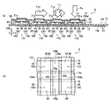
図12(a)は、荷重分布検出装置3の平面図であり、同図(b)は、荷重分布検出装置3の正面図である。また、図13(a)は、荷重分布検出装置3の底面図であり、同図(b)は、図12(a)のA−A線断面図である。また、図14(a)は、図13(b)のD−D線断面図であり、同図(b)および(c)は、複数位置に作用する荷重検出の概要を示した平面図である。   FIG. 12A is a plan view of the load distribution detection device 3, and FIG. 12B is a front view of the load distribution detection device 3. Moreover, Fig.13 (a) is a bottom view of the load distribution detection apparatus 3, and the same figure (b) is the sectional view on the AA line of Fig.12 (a). 14A is a cross-sectional view taken along the line D-D in FIG. 13B, and FIGS. 14B and C are plan views showing an outline of load detection acting on a plurality of positions. is there.

これらの図に示されるように、本実施形態の荷重分布検出装置3は、x方向に連続するx方向帯状電極12、およびy方向に連続するy方向帯状電極26に加え、平面視で右上がりの対角線L1方向に連続する対角線方向帯状電極13を備えている。そして、第1の固定電極32はx方向帯状電極12の一部として設けられ、第2の固定電極34は、対角線方向帯状電極13によって対角線L1方向に隣接する物同士が電気的に接続されると共に、配線14を介してまとめて制御装置60に接続されるように設けられている。   As shown in these drawings, the load distribution detection device 3 according to the present embodiment rises to the right in plan view in addition to the x-direction strip electrode 12 continuous in the x direction and the y-direction strip electrode 26 continuous in the y direction. The diagonal direction strip | belt-shaped electrode 13 continuous in the diagonal line L1 direction is provided. The first fixed electrode 32 is provided as a part of the x-direction band electrode 12, and the second fixed electrode 34 is electrically connected to each other in the diagonal L1 direction by the diagonal band electrode 13. At the same time, it is provided so as to be connected to the control device 60 via the wiring 14 collectively.

本実施形態では、y方向帯状電極26は、図8(b)に示した形状と同一の形状に構成され、可動電極40はy方向帯状電極26の一部として略円形状に構成されている。一方、x方向帯状電極12は、図13(a)および図14(a)に示されるように、図8(a)に示した形状において第1の固定電極32を略円環状にした形状、すなわち第2の固定電極32の中央部に孔部32aを設けた形状に構成されている。そして、図14(a)に示されるように、この孔部42a内に、略円形状の第2の固定電極34が設けられている。   In the present embodiment, the y-direction strip electrode 26 is configured in the same shape as the shape shown in FIG. 8B, and the movable electrode 40 is configured in a substantially circular shape as a part of the y-direction strip electrode 26. . On the other hand, as shown in FIGS. 13 (a) and 14 (a), the x-direction strip electrode 12 has a shape in which the first fixed electrode 32 is formed in a substantially annular shape in the shape shown in FIG. 8 (a). In other words, the second fixed electrode 32 is configured to have a shape in which a hole 32 a is provided at the center. Then, as shown in FIG. 14A, a substantially circular second fixed electrode 34 is provided in the hole 42a.

本実施形態では、基板10は、弾性部材20側の第1層10cおよび弾性部材20の反対側の第2層10dからなる2層構造となっており、x方向帯状電極12(固定電極30)および第2の固定電極34は、図14(a)に示されるように、この第1層10cと第2層10dの間に形成されている。そして、対角線方向帯状電極13は、図13(a)および(b)に示されるように、基板10の底面10b(すなわち、第2層10dの底面)に形成され、スルーホール18を介して、第2の固定電極34と電気的に接続されている。これにより、第2の固定電極34は、x方向およびy方向のいずれとも異なる対角線L1方向に隣接する物同士が電気的に接続されるようになっている。また、第2の固定電極34は、配線14を介して対角線方向帯状電極13ごとに制御装置60に接続されている。   In the present embodiment, the substrate 10 has a two-layer structure including a first layer 10c on the elastic member 20 side and a second layer 10d on the opposite side of the elastic member 20, and the x-direction strip electrode 12 (fixed electrode 30). As shown in FIG. 14A, the second fixed electrode 34 is formed between the first layer 10c and the second layer 10d. And the diagonal direction strip | belt-shaped electrode 13 is formed in the bottom face 10b (namely, bottom face of the 2nd layer 10d) of the board | substrate 10, as shown to Fig.13 (a) and (b), The second fixed electrode 34 is electrically connected. As a result, the second fixed electrode 34 is configured such that objects adjacent to each other in the diagonal L1 direction different from both the x direction and the y direction are electrically connected. In addition, the second fixed electrode 34 is connected to the control device 60 for each diagonal band-like electrode 13 via the wiring 14.

このように、本実施形態では、固定電極30として第1の固定電極32および第2の固定電極34を設けることで、第1の固定電極32および可動電極40の対からなる荷重検出用の検出要素100と略同位置に、第2の固定電極34および可動電極40の対からなり、荷重の位置を特定するための位置特定用検出要素106を設けるようにしている。そして、これにより、複雑な制御を必要とすることなく複数位置に作用する荷重を検出することを可能としている。   As described above, in the present embodiment, the first fixed electrode 32 and the second fixed electrode 34 are provided as the fixed electrode 30, thereby detecting the load for detection composed of the pair of the first fixed electrode 32 and the movable electrode 40. A position specifying detection element 106, which is a pair of the second fixed electrode 34 and the movable electrode 40 and for specifying the position of the load, is provided at substantially the same position as the element 100. As a result, it is possible to detect loads acting on a plurality of positions without requiring complicated control.

従って、本実施形態の制御装置60は、各検出要素100および各位置特定用検出要素106における静電容量の変化を検出する静電容量検出処理手段62と、各検出要素100における静電容量の変化量に基づいてz方向の荷重の大きさを導出する力学量換算処理手段64と、に加えて、複数のz方向の荷重の位置を特定する位置特定処理手段66を備えている。この位置特定処理手段66は、各位置特定用検出要素106における静電容量の変化量に基づく演算処理を実行することで、複数位置にz方向の荷重が作用した場合においても、荷重の位置を特定する。   Therefore, the control device 60 according to the present embodiment includes a capacitance detection processing unit 62 that detects a change in capacitance in each detection element 100 and each position specifying detection element 106, and the capacitance of each detection element 100. In addition to the mechanical quantity conversion processing means 64 for deriving the magnitude of the load in the z direction based on the amount of change, a position specifying processing means 66 for specifying the positions of a plurality of loads in the z direction is provided. The position specifying processing unit 66 executes a calculation process based on the amount of change in capacitance in each position specifying detection element 106, so that the position of the load can be determined even when a load in the z direction is applied to a plurality of positions. Identify.

図14(b)に示されるように、x方向に接続された固定電極30およびy方向に接続された可動電極40のみを備える荷重分布検出装置1においては、例えば弾性部材20の受力面21における位置P1、P2の2箇所に荷重Fzが作用した場合、例えば自己容量方式によっては、位置P1、P2の2箇所に荷重Fzが作用したのか、位置P3、P4の2箇所に荷重Fzが作用したのかを判別することが不可能となる、いわゆるゴースト現象が発生する。   As shown in FIG. 14B, in the load distribution detection device 1 including only the fixed electrode 30 connected in the x direction and the movable electrode 40 connected in the y direction, for example, the force receiving surface 21 of the elastic member 20. For example, depending on the self-capacitance method, the load Fz is applied to two positions P1 and P2, or the load Fz is applied to two positions P3 and P4. A so-called ghost phenomenon occurs in which it is impossible to determine whether the failure has occurred.

一方、同図(b)に示されるように、荷重分布検出装置3では、ゴースト現象が発生するような位置に複数の荷重Fzが作用した場合においても、いずれの位置特定用検出要素106の静電容量が変化したかに基づいて、複数の荷重Fzの位置を特定することができる。具体的に、位置特定処理手段66は、同図(b)に示されるように、例えば位置P1、P2の2箇所および位置P3、P4の2箇所のいずれに荷重Fzが作用しているかを検出要素100では判別できない場合に、いずれの対角線方向帯状電極13に繋がる(すなわち、いずれの対角線方向帯状電極13に接続された第2の固定電極34を含む)位置特定用検出要素106の静電容量が変化したかに基づいて、複数の荷重Fzの位置を特定する。   On the other hand, as shown in FIG. 5B, in the load distribution detection device 3, even when a plurality of loads Fz are applied at a position where the ghost phenomenon occurs, any of the position specifying detection elements 106 is statically detected. Based on whether the capacitance has changed, the positions of the plurality of loads Fz can be specified. Specifically, as shown in FIG. 5B, the position specifying processing unit 66 detects whether the load Fz is applied to, for example, two positions P1 and P2 and two positions P3 and P4. Capacitance of detecting element 106 for position identification connected to any diagonal strip electrode 13 (that is, including second fixed electrode 34 connected to any diagonal strip electrode 13) when element 100 cannot discriminate The positions of the plurality of loads Fz are specified based on whether or not has changed.

すなわち、同図(b)に示す例では、位置特定処理手段66は、位置P1、P4を通過するy方向帯状電極26−1に繋がる(すなわち、y方向帯状電極26−1に属する可動電極40を含む)4つの位置特定検出要素106のうち、位置P1を通過する対角線方向帯状電極13−1に繋がる位置特定用検出要素106における静電容量が変化し、位置P4を通過する対角線方向帯状電極13−4に繋がる位置特定用検出要素106における静電容量が変化しないことに基づいて、荷重Fzが位置P1に作用したことを検出する。位置特定処理手段66はまた、位置P2、P3を通過するy方向帯状電極26−2に繋がる4つの位置特定検出要素106のうち、位置P2を通過する対角線方向帯状電極13−2に繋がる位置特定用検出要素106における静電容量が変化し、位置P3を通過する対角線方向帯状電極13−3に繋がる位置特定用検出要素106における静電容量が変化しないことに基づいて、荷重Fzが位置P2に作用したことを検出する。   That is, in the example shown in FIG. 5B, the position specifying processing unit 66 is connected to the y-direction band electrode 26-1 passing through the positions P1 and P4 (that is, the movable electrode 40 belonging to the y-direction band electrode 26-1). Among the four position specifying detection elements 106), the capacitance in the position specifying detection element 106 connected to the diagonal band electrode 13-1 passing through the position P1 is changed, and the diagonal band electrode passing through the position P4 is changed. Based on the fact that the capacitance in the position specifying detection element 106 connected to 13-4 does not change, it is detected that the load Fz has acted on the position P1. The position specifying processing unit 66 also specifies the position connected to the diagonal band electrode 13-2 passing through the position P2 among the four position specifying detection elements 106 connected to the y-direction band electrode 26-2 passing through the positions P2 and P3. Based on the fact that the capacitance in the detection element 106 for use changes and the capacitance in the position detection element 106 connected to the diagonal strip electrode 13-3 passing through the position P3 does not change, the load Fz is changed to the position P2. Detecting that it has acted.

このように、本実施形態では、複雑な制御を採用しなくとも、ゴースト現象を回避することができるため、処理速度を向上させることが可能となっている。また、相互容量方式等の専用のワンチップマイコンを使用することなく、汎用のワンチップマイコン等から制御装置60を構成することができるため、コストを削減することが可能となっている。また、専用のワンチップマイコンによる制限がなくなるため、設計の自由度が向上している。   As described above, in the present embodiment, the ghost phenomenon can be avoided without employing complicated control, so that the processing speed can be improved. In addition, since the control device 60 can be configured from a general-purpose one-chip microcomputer or the like without using a dedicated one-chip microcomputer such as a mutual capacitance method, it is possible to reduce costs. In addition, since there is no restriction by a dedicated one-chip microcomputer, the degree of freedom in design is improved.

なお、第2の固定電極34の接続方向は、対角線L1方向に限定されるものではなく、第1の固定電極32の接続方向(x方向)および可動電極40の接続方向(y方向)のいずれとも異なる方向であればよい。また、第1の固定電極32および第2の固定電極34の形状および配置は、その他の適宜の形状および配置を採用することが可能である。同様に、可動電極40ならびに弾性部材20の凸部22および凹部24の形状および配置についても、その他の適宜の形状および配置を採用することが可能である。また、位置特定用検出要素106における静電容量変化を、z方向の荷重の導出に利用するようにしてもよい。また、z方向の荷重の導出を省略し、荷重が作用した位置のみを検出するようにしてもよい。また、第1の実施形態および第2の実施形態において示した各種構成を本実施形態の荷重分布検出装置3に適用してもよいことは言うまでもない。   Note that the connection direction of the second fixed electrode 34 is not limited to the diagonal L1 direction, and any of the connection direction of the first fixed electrode 32 (x direction) and the connection direction of the movable electrode 40 (y direction). Both directions may be different. Further, other appropriate shapes and arrangements can be adopted as the shapes and arrangements of the first fixed electrode 32 and the second fixed electrode 34. Similarly, other appropriate shapes and arrangements can be adopted for the shapes and arrangements of the movable electrode 40 and the convex portions 22 and the concave portions 24 of the elastic member 20. Further, the capacitance change in the position detection element 106 may be used to derive the load in the z direction. Alternatively, the derivation of the load in the z direction may be omitted, and only the position where the load is applied may be detected. Needless to say, the various configurations shown in the first embodiment and the second embodiment may be applied to the load distribution detection device 3 of the present embodiment.

<第4の実施形態>
次に、本発明の第4の実施形態に係る荷重分布検出装置4について説明する。本実施形態に係る荷重分布検出装置4は、受力面21の法線方向、すなわちz方向に作用する荷重の分布を検出するものであり、第1の固定電極32および第2の固定電極34に加えて、第3の固定電極36を設けることにより、荷重を受けて変形する弾性部材20に設けられる可動電極40の構成を簡素化することを可能としたものである。なお、以下の説明においては、第1および第3の実施形態の荷重分布検出装置1、3と同一の部分については同一の符号を付すと共にその説明を省略し、第1および第3の実施形態と異なる部分について説明する。
<Fourth Embodiment>
Next, a load distribution detection apparatus 4 according to the fourth embodiment of the present invention will be described. The load distribution detection device 4 according to the present embodiment detects the distribution of loads acting in the normal direction of the force receiving surface 21, that is, the z direction, and the first fixed electrode 32 and the second fixed electrode 34. In addition, by providing the third fixed electrode 36, it is possible to simplify the configuration of the movable electrode 40 provided on the elastic member 20 that is deformed by receiving a load. In the following description, the same parts as those of the load distribution detection devices 1 and 3 of the first and third embodiments are denoted by the same reference numerals and the description thereof is omitted, and the first and third embodiments are omitted. Different parts will be described.

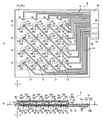
図15(a)は、荷重分布検出装置4の平面図であり、同図(b)は、荷重分布検出装置4の正面図である。また、図16(a)は、荷重分布検出装置4の底面図であり、同図(b)は、図15(a)のA−A線断面図である。また、図17(a)は、本実施形態における弾性部材20の平面図であり、同図(b)は、弾性部材20の底面図である。また、同図(c)は、同図(a)のB−B線断面図であり、同図(d)は、同図(a)のE−E線断面図である。   FIG. 15A is a plan view of the load distribution detection device 4, and FIG. 15B is a front view of the load distribution detection device 4. FIG. 16A is a bottom view of the load distribution detecting device 4, and FIG. 16B is a cross-sectional view taken along the line AA in FIG. FIG. 17A is a plan view of the elastic member 20 in the present embodiment, and FIG. 17B is a bottom view of the elastic member 20. FIG. 3C is a cross-sectional view taken along the line BB of FIG. 1A, and FIG. 4D is a cross-sectional view taken along the line EE of FIG.

図15(a)および図16(a)に示されるように、第1の固定電極32および第2の固定電極34は、それぞれ略コの字状に構成され、互いに斜め方向に向き合うように配置されている。また、第3の固定電極36は、略矩形状(略菱形状)に構成され、第1の固定電極32および第2の固定電極34の間に配置されている。換言すれば、第3の固定電極36の周囲を囲むような形状に、第1の固定電極32および第2の固定電極34は構成されている。   As shown in FIGS. 15 (a) and 16 (a), the first fixed electrode 32 and the second fixed electrode 34 are each formed in a substantially U-shape and arranged so as to face each other in an oblique direction. Has been. The third fixed electrode 36 is configured in a substantially rectangular shape (substantially diamond shape), and is disposed between the first fixed electrode 32 and the second fixed electrode 34. In other words, the first fixed electrode 32 and the second fixed electrode 34 are configured so as to surround the periphery of the third fixed electrode 36.

第1の固定電極32は、接続配線15を介してx方向に隣接するもの同士が電気的に接続されると共に、互いに電気的に接続された状態でまとめて配線14を介して制御装置60に接続されている。また、第2の固定電極34は、接続配線15を介してy方向に隣接するもの同士が電気的に接続されると共に、互いに電気的に接続された状態でまとめて配線14を介して制御装置60に接続されている。そして、第3の固定電極36は、平面視で左上がりの対角線L2方向に連続する対角線方向帯状電極13の一部として構成され、配線14を介して対角線方向帯状電極13ごと制御装置60に接続されている。   The first fixed electrodes 32 that are adjacent to each other in the x direction via the connection wiring 15 are electrically connected to each other and are collectively connected to the control device 60 via the wiring 14 while being electrically connected to each other. It is connected. The second fixed electrodes 34 are electrically connected to each other adjacent to each other in the y direction via the connection wiring 15 and are collectively connected to each other via the wiring 14 while being electrically connected to each other. 60. The third fixed electrode 36 is configured as a part of the diagonal strip electrode 13 that continues in the diagonally upward diagonal L2 direction in plan view, and is connected to the control device 60 together with the diagonal strip electrode 13 via the wiring 14. Has been.

本実施形態では、図16(a)に示されるように、第1の固定電極32、第2の固定電極34、第3の固定電極36(対角線方向帯状電極13)および接続電極15を基板10の底面10bに設けている。従って、本実施形態では、接続配線15の途中にジャンパ配線15aおよび絶縁層15bを設けることで、互いに交差することとなる第1の固定電極32を接続する接続配線15、第2の固定電極34を接続する接続配線15、および対角線方向帯状電極13が電気的に短絡しないようにしている。   In this embodiment, as shown in FIG. 16A, the first fixed electrode 32, the second fixed electrode 34, the third fixed electrode 36 (diagonal band electrode 13), and the connection electrode 15 are attached to the substrate 10. Is provided on the bottom surface 10b. Therefore, in this embodiment, by providing the jumper wiring 15a and the insulating layer 15b in the middle of the connection wiring 15, the connection wiring 15 and the second fixed electrode 34 that connect the first fixed electrodes 32 that intersect each other. Are not electrically short-circuited with the connection wiring 15 and the diagonal strip electrode 13.

弾性部材20は、図17(a)〜(d)に示されるように、第1〜第3の固定電極32、34、36の形状および配置に合わせて凸部22および凹部24が底面20bに形成されている。そして、可動電極40は、弾性部材20の底面20bにおいて、第1〜第3の固定電極32、34、36の全てと対向する1つの電極として設けられている。換言すれば、可動電極40は、複数の第1〜第3の固定電極32、34、36にそれぞれ対向する複数の電極が、全て互いに接続された状態となっている。   As shown in FIGS. 17A to 17D, the elastic member 20 has a convex portion 22 and a concave portion 24 on the bottom surface 20b in accordance with the shape and arrangement of the first to third fixed electrodes 32, 34, and 36. Is formed. The movable electrode 40 is provided as one electrode facing all of the first to third fixed electrodes 32, 34, 36 on the bottom surface 20 b of the elastic member 20. In other words, the movable electrode 40 is in a state where a plurality of electrodes respectively opposed to the plurality of first to third fixed electrodes 32, 34, 36 are connected to each other.

このような電極構成により、本実施形態では、荷重検出用の検出要素100として、第1の固定電極32および可動電極40の対からなる第1の検出要素100a、および第2の固定電極34および可動電極40の対からなる第2の検出要素100bを略同位置に設けると共に、これらと略同位置にさらに、第3の固定電極36および可動電極40の対からなる位置特定用検出要素106を設けるようにしている。   With such an electrode configuration, in this embodiment, as the detection element 100 for load detection, the first detection element 100a formed of a pair of the first fixed electrode 32 and the movable electrode 40, the second fixed electrode 34, and A second detection element 100b composed of a pair of movable electrodes 40 is provided at substantially the same position, and a position specifying detection element 106 composed of a pair of the third fixed electrode 36 and the movable electrode 40 is further provided at substantially the same position as these. I am trying to provide it.

従って、本実施形態の制御装置60は、各第1の検出要素100a、各第2の検出要素100bおよび各位置特定用検出要素106における静電容量の変化を検出する静電容量検出処理手段62と、各第1の検出要素100aおよび各第2の検出要素100bにおける静電容量の変化量に基づいてz方向の荷重の大きさを導出する力学量換算処理手段64と、各位置特定用検出要素106における静電容量の変化量に基づいて複数のz方向の荷重の位置を特定する位置特定処理手段66を備えている。   Therefore, the control device 60 according to the present embodiment detects the capacitance change in each first detection element 100a, each second detection element 100b, and each position specifying detection element 106. And a mechanical quantity conversion processing means 64 for deriving the magnitude of the load in the z direction based on the amount of change in capacitance in each first detection element 100a and each second detection element 100b, and each position specifying detection Position specifying processing means 66 for specifying the positions of a plurality of loads in the z direction based on the amount of change in capacitance in the element 106 is provided.

これにより、本実施形態では、第3の実施形態と同様に、複雑な制御を採用しなくともゴースト現象を回避することができるため、処理速度を向上させることが可能となっている。すなわち、第1の検出要素100aおよび第2の検出要素100bにおける静電容量変化によって複数のz方向の荷重の位置を検出する際にゴースト現象が発生するような場合であっても、位置特定用検出要素106における静電容量の変化によって複数のz方向の荷重の位置を特定することができる。また、汎用のワンチップマイコン等から制御装置60を構成することができるため、コストを削減すると共に、設計の自由度を向上させることが可能となっている。   Thus, in the present embodiment, similarly to the third embodiment, the ghost phenomenon can be avoided without adopting complicated control, so that the processing speed can be improved. That is, even if a ghost phenomenon occurs when detecting the positions of a plurality of loads in the z direction due to capacitance changes in the first detection element 100a and the second detection element 100b, The position of a plurality of loads in the z direction can be specified by a change in capacitance in the detection element 106. In addition, since the control device 60 can be configured from a general-purpose one-chip microcomputer or the like, it is possible to reduce costs and improve design flexibility.

さらに、本実施形態では、所定の方向に隣接されるもの同士が電気的に接続される電極を全て基板10に設けられる固定電極30としているため、荷重を受けて繰り返し変形する弾性部材20に設けられる可動電極40の構成を簡素化することが可能となっている。これにより、製造コストを低減すると共に、弾性部材20および可動電極40の強度および耐久性を高めることができる。また、弾性部材20の形状の自由度が高まるため、装置の強度および耐久性を高めつつ、装置全体のさらなる薄型化、コンパクト化を図ることも可能となっている。   Furthermore, in this embodiment, since the electrodes that are electrically connected to each other adjacent to each other in a predetermined direction are the fixed electrodes 30 provided on the substrate 10, they are provided on the elastic member 20 that repeatedly deforms under a load. It is possible to simplify the configuration of the movable electrode 40 to be provided. Thereby, while reducing manufacturing cost, the intensity | strength and durability of the elastic member 20 and the movable electrode 40 can be improved. Further, since the degree of freedom of the shape of the elastic member 20 is increased, it is possible to further reduce the thickness and size of the entire device while increasing the strength and durability of the device.

なお、第1〜第3の固定電極32、34、36の接続方向は、それぞれx方向、y方向および対角線L2方向に限定されるものではなく、互いに異なる方向であればその他の方向であってもよい。また、第1〜第3の固定電極32、34、36の形状および配置は、その他の適宜の形状および配置を採用することが可能である。同様に、可動電極40ならびに弾性部材20の凸部22および凹部24の形状および配置についても、その他の適宜の形状および配置を採用することが可能である。また、位置特定用検出要素106における静電容量変化を、z方向の荷重の導出に利用するようにしてもよい。また、z方向の荷重の導出を省略し、荷重が作用した位置のみを検出するようにしてもよい。また、対角線方向帯状電極13および第3の固定電極36を省略し、位置特定用検出要素106および位置特定処理手段66を設けないシンプルな構成としてもよい。また、第1の実施形態および第2の実施形態において示した各種構成を本実施形態の荷重分布検出装置3に適用してもよいことは言うまでもない。   Note that the connection directions of the first to third fixed electrodes 32, 34, and 36 are not limited to the x direction, the y direction, and the diagonal L2 direction, respectively. Also good. Further, other appropriate shapes and arrangements can be adopted as the shapes and arrangements of the first to third fixed electrodes 32, 34, and 36. Similarly, other appropriate shapes and arrangements can be adopted for the shapes and arrangements of the movable electrode 40 and the convex portions 22 and the concave portions 24 of the elastic member 20. Further, the capacitance change in the position detection element 106 may be used to derive the load in the z direction. Alternatively, the derivation of the load in the z direction may be omitted, and only the position where the load is applied may be detected. Alternatively, the diagonal band electrode 13 and the third fixed electrode 36 may be omitted, and the position specifying detection element 106 and the position specifying processing unit 66 may be omitted. Needless to say, the various configurations shown in the first embodiment and the second embodiment may be applied to the load distribution detection device 3 of the present embodiment.

また、弾性部材20を例えば導電性ゴム等の導電性の材料から構成し、弾性部材20自体を可動電極40とするようにしてもよい。なお、この場合、弾性部材20とシールド電極50の間に絶縁層を設ける等して、弾性部材20(すなわち、可動電極40)とシールド電極50が電気的に短絡しないように構成することが好ましい。このように、弾性部材20自体を可動電極40とすることで、弾性部材20および可動電極40をさらに簡素化することが可能となるため、装置の強度および耐久性をより高めつつ、装置全体をさらに薄型化、コンパクト化することが可能となる。   Alternatively, the elastic member 20 may be made of a conductive material such as conductive rubber, and the elastic member 20 itself may be used as the movable electrode 40. In this case, it is preferable that the elastic member 20 (that is, the movable electrode 40) and the shield electrode 50 are not electrically short-circuited by providing an insulating layer between the elastic member 20 and the shield electrode 50. . Thus, by making the elastic member 20 itself the movable electrode 40, it becomes possible to further simplify the elastic member 20 and the movable electrode 40. Therefore, while further improving the strength and durability of the device, Furthermore, it becomes possible to make it thin and compact.

また、本実施形態では、第1の固定電極32および可動電極40の対からなる第1の検出要素100a、第2の固定電極34および可動電極40の対からなる第2の検出要素100b、および第3の固定電極36および可動電極40の対からなる位置特定用検出要素106を設けるようにした例を示したが、第1の検出要素100aおよび第2の検出要素100bの代わりに、第1の固定電極32および第2の固定電極34と可動電極40の対からなる検出要素100を設けるようにしてもよい。すなわち、2つの固定電極30(第1の固定電極32および第2の固定電極34)の間における静電容量が、可動電極40の移動(変位)に伴って変化するのを検出するようにしてもよい。さらに、位置特定用検出要素106についても、第1の固定電極32および第3の固定電極36と可動電極40の対、または第2の固定電極34および第3の固定電極36と可動電極40の対から構成し、可動電極40の移動(変位)に伴う2つの固定電極30の間における静電容量の変化を検出するようにしてもよい。   In the present embodiment, the first detection element 100a composed of a pair of the first fixed electrode 32 and the movable electrode 40, the second detection element 100b composed of the pair of the second fixed electrode 34 and the movable electrode 40, and Although the example in which the position specifying detection element 106 including the pair of the third fixed electrode 36 and the movable electrode 40 is provided is shown, the first detection element 100a and the second detection element 100b are replaced by the first detection element 106a. Alternatively, the detection element 100 including the fixed electrode 32 and the second fixed electrode 34 and the movable electrode 40 may be provided. That is, it is detected that the capacitance between the two fixed electrodes 30 (the first fixed electrode 32 and the second fixed electrode 34) changes as the movable electrode 40 moves (displaces). Also good. Further, with respect to the position detection element 106, a pair of the first fixed electrode 32 and the third fixed electrode 36 and the movable electrode 40 or a pair of the second fixed electrode 34 and the third fixed electrode 36 and the movable electrode 40 is used. It may be configured by a pair, and a change in capacitance between the two fixed electrodes 30 accompanying the movement (displacement) of the movable electrode 40 may be detected.

以上説明したように、上記各実施形態に係る荷重分布検出装置1〜4は、検出面(x−y平面)内における荷重の分布を検出する荷重分布検出装置であって、検出面に沿って配列される複数の固定電極30と、固定電極30に対向して設けられる可動電極40と、固定電極30および可動電極40の対からなる複数の静電容量検出部(検出要素100、第1の検出要素100a、第2の検出要素100b、z方向専用検出要素102および位置特定用検出要素106)と、可動電極40に対して固定電極30の反対側に設けられるシールド電極50と、を備え、固定電極30は、所定の方向に隣接するもの同士が電気的に接続されている。   As described above, the load distribution detection devices 1 to 4 according to the above embodiments are load distribution detection devices that detect a load distribution in the detection surface (xy plane), and follow the detection surface. A plurality of fixed electrodes 30 arranged, a movable electrode 40 provided to face the fixed electrode 30, and a plurality of capacitance detection units (detection elements 100, first electrodes) each including a pair of the fixed electrode 30 and the movable electrode 40. A detection element 100a, a second detection element 100b, a z-direction dedicated detection element 102 and a position detection element 106), and a shield electrode 50 provided on the opposite side of the fixed electrode 30 with respect to the movable electrode 40, The fixed electrodes 30 adjacent to each other in a predetermined direction are electrically connected.

このような構成とすることで、簡素且つ安価な構成でありながらも、用途を問わず、荷重分布を高精度に検出することができる。すなわち、所定の方向に隣接する固定電極50同士を電気的に接続することにより、処理負荷を増大させることなく広範囲における荷重分布を高速に検出するだけではなく、シールド電極50を設けることによって、荷重を加える外部の物体の材質や静電気等に影響されることなく荷重分布を検出することが可能となる。さらに、固定電極30の構成および接続態様を工夫することにより、従来の装置では困難であった面方向荷重の検出や複数荷重の位置の特定等を、簡素且つ安価な構成で実現することができる。   By adopting such a configuration, the load distribution can be detected with high accuracy regardless of the application, though the configuration is simple and inexpensive. That is, by electrically connecting the fixed electrodes 50 adjacent to each other in a predetermined direction, not only can the load distribution in a wide range be detected at high speed without increasing the processing load, but also by providing the shield electrode 50, the load It is possible to detect the load distribution without being affected by the material of the external object to be applied, static electricity or the like. Furthermore, by devising the configuration and connection mode of the fixed electrode 30, it is possible to realize the detection of the surface direction load, the specification of the positions of the plurality of loads, etc., which are difficult with the conventional apparatus, with a simple and inexpensive configuration. .

また、荷重分布検出装置1〜4は、弾性材料から構成され、検出面に沿って配置される略シート状の弾性部材20を備え、可動電極40およびシールド電極50は、弾性部材20に設けられている。このようにすることで、装置全体を簡素且つ安価に構成すると共に、従来の装置と比較して薄型化、コンパクト化することができる。さらに、可動電極40の移動およびこれに伴う静電容量の変化を適宜に設定することが可能となるため、検出精度を向上させることが可能となる。   The load distribution detection devices 1 to 4 include a substantially sheet-like elastic member 20 made of an elastic material and disposed along the detection surface. The movable electrode 40 and the shield electrode 50 are provided on the elastic member 20. ing. In this way, the entire apparatus can be configured simply and inexpensively, and can be made thinner and more compact as compared with conventional apparatuses. Furthermore, since it is possible to appropriately set the movement of the movable electrode 40 and the change in electrostatic capacity associated therewith, it is possible to improve the detection accuracy.

また、荷重分布検出装置3および4では、固定電極30は、第1の方向(x方向)に隣接するもの同士が電気的に接続される第1の固定電極32と、第1の方向と交差する第2の方向(荷重分布検出装置3では対角線L1方向、荷重分布検出装置4ではy方向)に隣接するもの同士が電気的に接続される第2の固定電極34と、を含んでいる。このようにすることで、例えば複数荷重の位置の特定を容易にしたり、荷重を受ける弾性部材20をより簡素に構成したりすることが可能となるため、装置の適用範囲を拡大し、様々な用途に使用することができる。   In the load distribution detection devices 3 and 4, the fixed electrode 30 intersects the first fixed electrode 32 to which the adjacent ones in the first direction (x direction) are electrically connected, and the first direction. And a second fixed electrode 34 that is electrically connected to each other in the second direction (the diagonal L1 direction in the load distribution detection device 3 and the y direction in the load distribution detection device 4). In this way, for example, it is possible to easily specify the position of a plurality of loads or to more simply configure the elastic member 20 that receives the load. Can be used for applications.

また、荷重分布検出装置3では、可動電極40は、1組の第1の固定電極32および第2の固定電極34ごとに複数設けられると共に、第1の方向(x方向)および第2の方向(対角線L1方向)のいずれとも異なる第3の方向(y方向)に隣接するもの同士が電気的に接続されている。このようにすることで、複雑な制御を採用することなく、複数の荷重位置の特定を容易に行うことができる。   In the load distribution detection device 3, a plurality of movable electrodes 40 are provided for each pair of the first fixed electrode 32 and the second fixed electrode 34, and the first direction (x direction) and the second direction are provided. Those adjacent in a third direction (y direction) different from any of (diagonal line L1 direction) are electrically connected. By doing so, it is possible to easily identify a plurality of load positions without employing complicated control.

また、荷重分布検出装置3は、第2の固定電極34および可動電極40の対からなる静電容量検出部(位置特定用検出要素106)における静電容量の変化に基づき、検出面内における荷重の位置を特定する位置特定処理手段66を備えている。このようにすることで、複数の荷重位置の特定を容易にし、荷重分布の検出を高速化することができる。   Further, the load distribution detection device 3 is based on a change in capacitance in a capacitance detection unit (position specifying detection element 106) composed of a pair of the second fixed electrode 34 and the movable electrode 40. There is provided position specifying processing means 66 for specifying the position. By doing in this way, specification of a some load position can be made easy and the detection of load distribution can be sped up.

また、荷重分布検出装置4では、可動電極40は、全ての固定電極30に対向する1つの電極として設けられている。このようにすることで、弾性部材20の構成をより簡素化すると共に形状の自由度を高めることが可能となるため、強度および耐久性を向上させたり、検出精度を向上させたり等することで、装置の汎用性をさらに高めることができる。   In the load distribution detection device 4, the movable electrode 40 is provided as one electrode facing all the fixed electrodes 30. By doing in this way, since it becomes possible to simplify the structure of the elastic member 20 and to raise the freedom degree of a shape, by improving an intensity | strength and durability, improving a detection precision, etc. The versatility of the apparatus can be further enhanced.

また、荷重分布検出装置4では、固定電極30は、第1の方向(x方向)および第2の方向(y方向)のいずれとも異なる第3の方向(対角線L2方向)に隣接するもの同士が電気的に接続される第3の固定電極36をさらに含んでいる。このようにすることで、複雑な制御を採用することなく、複数の荷重位置の特定を容易に行うことが可能となるため、装置の汎用性をさらに高めることができる。   In the load distribution detection device 4, the fixed electrodes 30 are adjacent to each other in a third direction (diagonal L2 direction) different from both the first direction (x direction) and the second direction (y direction). A third fixed electrode 36 that is electrically connected is further included. By doing in this way, since it becomes possible to identify a some load position easily, without employ | adopting complicated control, the versatility of an apparatus can further be improved.

また、荷重分布検出装置4では、第3の固定電極36および可動電極40の対からなる静電容量検出部(位置特定用検出要素106)における静電容量の変化に基づき、検出面内における荷重の位置を特定する位置特定処理手段66を備えている。このようにすることで、複数の荷重位置の特定を容易にし、荷重分布の検出を高速化することが可能となるため、装置の汎用性をさらに高めることができる。   Further, in the load distribution detection device 4, the load in the detection surface is based on the change in the capacitance in the capacitance detection unit (position specifying detection element 106) composed of the pair of the third fixed electrode 36 and the movable electrode 40. There is provided position specifying processing means 66 for specifying the position. By doing so, it is possible to easily specify a plurality of load positions and to speed up the detection of the load distribution, thereby further enhancing the versatility of the apparatus.

また、荷重分布検出装置2は、静電容量検出部(検出要素100)における静電容量の変化に基づいて、検出面の法線方向に作用する法線方向荷重(z方向の荷重Fz)を導出し、互いに近接する複数の静電容量検出部における静電容量の変化に基づいて、検出面の面方向に作用する面方向荷重(x−y平面内の荷重Fxy)を導出する力学量換算処理手段66を備えている。このようにすることで、簡素な構成および制御方式を採用しながらも、従来の装置では検出が困難であった面方向荷重の分布を、法線方向荷重の分布と共に検出することが可能となるため、装置の汎用性をさらに高めることができる。なお、荷重分布検出装置3および4において、面方向荷重の導出機能を設けるようにしてもよいことは言うまでもない。   In addition, the load distribution detection device 2 generates a normal direction load (a load Fz in the z direction) that acts in the normal direction of the detection surface based on a change in capacitance in the capacitance detection unit (detection element 100). Derived and converted into a mechanical quantity for deriving a surface direction load (load Fxy in the xy plane) acting in the surface direction of the detection surface based on the change in capacitance in a plurality of capacitance detection units adjacent to each other Processing means 66 is provided. In this way, while adopting a simple configuration and control method, it is possible to detect the distribution of the surface direction load, which was difficult to detect with the conventional apparatus, together with the distribution of the normal direction load. Therefore, the versatility of the apparatus can be further enhanced. Needless to say, the load distribution detection devices 3 and 4 may be provided with a function of deriving a surface direction load.

また、力学量換算処理手段66は、互いに近接する少なくとも3箇所の静電容量検出部における静電容量の変化量の重心位置を算出することにより、面方向荷重を導出するものであってもよい。この場合、電極の構成をより簡素化することが可能になると共に、面方向荷重の導出を高速化、高精度化することができる。   Further, the mechanical quantity conversion processing means 66 may derive the surface direction load by calculating the gravity center position of the change amount of the capacitance in at least three capacitance detection units close to each other. . In this case, the configuration of the electrode can be further simplified, and the derivation of the surface load can be speeded up and made highly accurate.

また、荷重分布検出装置1〜4は、絶縁性の材料から構成され、検出面に沿って配置される略シート状の絶縁部材(基板10)を備え、固定電極30は、絶縁部材に設けられている。このようにすることで、基板10とは別に絶縁層を設ける必要がなくなるため、装置全体をより簡素化、薄型化することができる。   The load distribution detection devices 1 to 4 are made of an insulating material and include a substantially sheet-like insulating member (substrate 10) disposed along the detection surface, and the fixed electrode 30 is provided on the insulating member. ing. By doing in this way, since it becomes unnecessary to provide an insulating layer separately from the board | substrate 10, the whole apparatus can be simplified more and thinned.

また、荷重分布検出装置1〜4では、絶縁部材(基板10)は、絶縁性の弾性材料(樹脂フィルム)から構成されている。このようにすることで、例えば曲面に沿って装置を配置したり、荷重を受ける際に荷重を加える物体に沿って装置全体をたわみ変形させたり等することが可能となるため、装置の汎用性をさらに高めることができる。   Moreover, in the load distribution detection apparatuses 1 to 4, the insulating member (substrate 10) is made of an insulating elastic material (resin film). In this way, for example, the apparatus can be arranged along a curved surface, or the entire apparatus can be bent and deformed along an object to which a load is applied when receiving a load. Can be further enhanced.

また、荷重分布検出装置1〜4は、弾性材料から構成され、絶縁部材(基板10)に対して弾性部材20の反対側に配置される略シート状の補助弾性部材70を備えるものであってもよい。このようにすることで、装置の強度および合成を用途や使用環境等に応じて適宜に設定することができる。   The load distribution detection devices 1 to 4 include a substantially sheet-like auxiliary elastic member 70 made of an elastic material and disposed on the opposite side of the elastic member 20 with respect to the insulating member (substrate 10). Also good. By doing in this way, the intensity | strength and synthesis | combination of an apparatus can be set suitably according to a use, use environment, etc.

また、補助弾性部材70は、絶縁性の材料から構成され、固定電極30は、絶縁部材(基板10)と補助弾性部材70の間に設けられるようにしてもよい。このようにすることで、補助弾性部材70を簡素且つコンパクトな構成でありながらも、固定電極30を適宜に保護すると共に、外部の機器との電気的短絡を適宜に防止することができる。   The auxiliary elastic member 70 may be made of an insulating material, and the fixed electrode 30 may be provided between the insulating member (substrate 10) and the auxiliary elastic member 70. In this way, while the auxiliary elastic member 70 has a simple and compact configuration, the fixed electrode 30 can be appropriately protected and an electrical short circuit with an external device can be appropriately prevented.

また、荷重分布検出装置1〜4は、固定電極30に対して可動電極40の反対側に配置される補助シールド電極52を備えるものであってもよい。このようにすることで、周囲の静電気等の影響をより効果的に排除することが可能となるため、検出精度を高めると共に装置の汎用性を高めることができる。   Further, the load distribution detection devices 1 to 4 may include an auxiliary shield electrode 52 disposed on the opposite side of the movable electrode 40 with respect to the fixed electrode 30. By doing so, it is possible to more effectively eliminate the influence of surrounding static electricity and the like, so that the detection accuracy can be enhanced and the versatility of the apparatus can be enhanced.

以上、本発明の実施の形態について説明したが、本発明の荷重分布検出装置は、上記した実施の形態に限定されるものではなく、本発明の要旨を逸脱しない範囲内において種々変更を加え得ることは勿論である。   As mentioned above, although embodiment of this invention was described, the load distribution detection apparatus of this invention is not limited to above-described embodiment, In the range which does not deviate from the summary of this invention, a various change can be added. Of course.

例えば、基板10の材質は、樹脂に限定されるものではなく、例えば各種絶縁ゴムやガラス、セラミックス等、その他の適宜の材質を採用することが可能であり、弾性部材20の材質についても、弾性変形可能な材質であればその他の材質であってもよい。また、検出面は、x−y平面に限定されるものではなく、例えばx−z平面や所定の斜面等であってもよいし、受力面21または装置全体を曲面状に構成することにより、検出面を曲面とするようにしてもよい。また、固定電極30および可動電極40等と制御装置60の接続は、リード線等を介したものであってもよい。   For example, the material of the substrate 10 is not limited to the resin, and other appropriate materials such as various insulating rubbers, glasses, ceramics, and the like can be employed. The elastic member 20 is also elastic. Other materials may be used as long as they are deformable. Further, the detection surface is not limited to the xy plane, and may be, for example, an xz plane, a predetermined slope, or the like, and the force receiving surface 21 or the entire apparatus is configured in a curved shape. The detection surface may be a curved surface. Further, the connection between the fixed electrode 30 and the movable electrode 40 and the control device 60 may be via a lead wire or the like.

また、上記実施形態において示した作用および効果は、本発明から生じる最も好適な作用および効果を列挙したものに過ぎず、本発明による作用および効果は、これらに限定されるものではない。   In addition, the functions and effects shown in the above embodiment are merely a list of the most preferable functions and effects resulting from the present invention, and the functions and effects of the present invention are not limited to these.

本発明の荷重分布検出装置は、例えばタッチパネルやロボット等、荷重分布の検出を必要とする各種機器において利用することができる。   The load distribution detection apparatus of the present invention can be used in various devices that require detection of load distribution, such as a touch panel and a robot.

1、2、3、4 荷重分布検出装置
10 基板
20 弾性部材
30 固定電極
30a z方向専用固定電極
32 第1の固定電極
34 第2の固定電極
36 第3の固定電極
40 可動電極
40a z方向専用可動電極
50 シールド電極
52 補助シールド電極
60 制御装置
64 力学量換算処理手段
66 位置特定処理手段
70 補助弾性部材
100 検出要素
100a 第1の検出要素
100b 第2の検出要素
102 z方向専用検出要素
106 位置特定用検出要素
1, 2, 3, 4 Load distribution detection device 10 Substrate 20 Elastic member 30 Fixed electrode 30a Fixed z-direction electrode 32 First fixed electrode 34 Second fixed electrode 36 Third fixed electrode 40 Movable electrode 40a Exclusive for z-direction Movable electrode 50 Shield electrode 52 Auxiliary shield electrode 60 Control device 64 Mechanical quantity conversion processing means 66 Position specifying processing means 70 Auxiliary elastic member 100 Detection element 100a First detection element 100b Second detection element 102 z-direction dedicated detection element 106 Position Detection element for identification

Claims (15)

検出面内における荷重の分布を検出する荷重分布検出装置であって、
前記検出面に沿って配列される複数の固定電極と、
前記固定電極に対向して設けられる可動電極と、
前記固定電極および前記可動電極の対からなる複数の静電容量検出部と、
前記可動電極に対して前記固定電極の反対側に設けられるシールド電極と、を備え、
前記固定電極は、所定の方向に隣接するもの同士が電気的に接続されることを特徴とする、
荷重分布検出装置。
A load distribution detection device that detects a load distribution in a detection plane,
A plurality of fixed electrodes arranged along the detection surface;
A movable electrode provided facing the fixed electrode;
A plurality of capacitance detectors composed of a pair of the fixed electrode and the movable electrode;
A shield electrode provided on the opposite side of the fixed electrode with respect to the movable electrode, and
The fixed electrodes are electrically connected to each other adjacent in a predetermined direction,
Load distribution detection device.
弾性材料から構成され、前記検出面に沿って配置される略シート状の弾性部材を備え、
前記可動電極および前記シールド電極は、前記弾性部材に設けられることを特徴とする、
請求項1に記載の荷重分布検出装置。
It is made of an elastic material, and includes a substantially sheet-like elastic member arranged along the detection surface,
The movable electrode and the shield electrode are provided on the elastic member,
The load distribution detection apparatus according to claim 1.
前記固定電極は、
第1の方向に隣接するもの同士が電気的に接続される第1の固定電極と、
前記第1の方向と交差する第2の方向に隣接するもの同士が電気的に接続される第2の固定電極と、を含むことを特徴とする、
請求項1または2に記載の荷重分布検出装置。
The fixed electrode is
A first fixed electrode in which the ones adjacent in the first direction are electrically connected;
A second fixed electrode that is electrically connected to each other adjacent to the second direction intersecting the first direction,
The load distribution detection device according to claim 1 or 2.
前記可動電極は、1組の前記第1の固定電極および前記第2の固定電極ごとに複数設けられると共に、前記第1の方向および前記第2の方向のいずれとも異なる第3の方向に隣接するもの同士が電気的に接続されることを特徴とする、
請求項3に記載の荷重分布検出装置。
A plurality of the movable electrodes are provided for each pair of the first fixed electrode and the second fixed electrode, and are adjacent to a third direction different from both the first direction and the second direction. It is characterized in that things are electrically connected to each other,
The load distribution detection apparatus according to claim 3.
前記第2の固定電極および前記可動電極の対からなる前記静電容量検出部における静電容量の変化に基づき、前記検出面内における荷重の位置を特定する位置特定処理手段を備えることを特徴とする、
請求項4に記載の荷重分布検出装置。
It comprises a position specifying processing means for specifying a position of a load in the detection surface based on a change in capacitance in the capacitance detecting unit comprising the pair of the second fixed electrode and the movable electrode. To
The load distribution detection apparatus according to claim 4.
前記可動電極は、全ての前記固定電極に対向する1つの電極として設けられることを特徴とする、
請求項3に記載の荷重分布検出装置。
The movable electrode is provided as one electrode facing all the fixed electrodes,
The load distribution detection apparatus according to claim 3.
前記固定電極は、前記第1の方向および前記第2の方向のいずれとも異なる第3の方向に隣接するもの同士が電気的に接続される第3の固定電極をさらに含むことを特徴とする、
請求項6に記載の荷重分布検出装置。
The fixed electrode further includes a third fixed electrode that is electrically connected to ones adjacent to each other in a third direction different from both the first direction and the second direction.
The load distribution detection apparatus according to claim 6.
前記第3の固定電極および前記可動電極の対からなる前記静電容量検出部における静電容量の変化に基づき、前記検出面内における荷重の位置を特定する位置特定処理手段を備えることを特徴とする、
請求項7に記載の荷重分布検出装置。
And a position specifying processing means for specifying a position of a load in the detection surface based on a change in capacitance in the capacitance detecting unit comprising the pair of the third fixed electrode and the movable electrode. To
The load distribution detection apparatus according to claim 7.
前記静電容量検出部における静電容量の変化に基づいて、前記検出面の法線方向に作用する法線方向荷重を導出し、互いに近接する複数の前記静電容量検出部における静電容量の変化に基づいて、前記検出面の面方向に作用する面方向荷重を導出する力学量換算処理手段を備えることを特徴とする、
請求項1乃至8のいずれかに記載の荷重分布検出装置。
Based on the change in capacitance in the capacitance detection unit, a normal direction load acting in the normal direction of the detection surface is derived, and the capacitance in the plurality of capacitance detection units close to each other is derived. Based on a change, characterized in that it comprises a mechanical quantity conversion processing means for deriving a surface direction load acting on the surface direction of the detection surface,
The load distribution detection device according to any one of claims 1 to 8.
前記力学量換算処理手段は、互いに近接する少なくとも3箇所の静電容量検出部における静電容量の変化量の重心位置を算出することにより、前記面方向荷重を導出することを特徴とする、
請求項9に記載の荷重分布検出装置。
The mechanical quantity conversion processing means derives the plane direction load by calculating the center of gravity position of the amount of change in capacitance in at least three capacitance detection units adjacent to each other.
The load distribution detection apparatus according to claim 9.
絶縁性の材料から構成され、前記検出面に沿って配置される略シート状の絶縁部材を備え、
前記固定電極は、前記絶縁部材に設けられることを特徴とする、
請求項1乃至10のいずれかに記載の荷重分布検出装置。
Consists of an insulating material, comprising a substantially sheet-like insulating member disposed along the detection surface,
The fixed electrode is provided on the insulating member,
The load distribution detection apparatus according to any one of claims 1 to 10.
前記絶縁部材は、絶縁性の弾性材料から構成されることを特徴とする、
請求項11に記載の荷重分布検出装置。
The insulating member is composed of an insulating elastic material,
The load distribution detection device according to claim 11.
弾性材料から構成され、前記絶縁部材に対して前記弾性部材の反対側に配置される略シート状の補助弾性部材を備えることを特徴とする、
請求項11または12に記載の荷重分布検出装置。
It is made of an elastic material and includes a substantially sheet-like auxiliary elastic member disposed on the opposite side of the elastic member with respect to the insulating member.
The load distribution detection device according to claim 11 or 12.
前記補助弾性部材は、絶縁性の材料から構成され、
前記固定電極は、前記絶縁部材と前記補助弾性部材の間に設けられることを特徴とする、
請求項13に記載の荷重分布検出装置。
The auxiliary elastic member is made of an insulating material,
The fixed electrode is provided between the insulating member and the auxiliary elastic member,
The load distribution detection device according to claim 13.
前記固定電極に対して前記可動電極の反対側に配置される補助シールド電極を備えることを特徴とする、
請求項1乃至14のいずれかに記載の荷重分布検出装置。
The auxiliary shield electrode disposed on the opposite side of the movable electrode with respect to the fixed electrode,
The load distribution detection apparatus according to any one of claims 1 to 14.
JP2013009141A 2013-01-22 2013-01-22 Load distribution detector Pending JP2014142193A (en)

Priority Applications (1)

Application Number Priority Date Filing Date Title
JP2013009141A JP2014142193A (en) 2013-01-22 2013-01-22 Load distribution detector

Applications Claiming Priority (1)

Application Number Priority Date Filing Date Title
JP2013009141A JP2014142193A (en) 2013-01-22 2013-01-22 Load distribution detector

Publications (1)

Publication Number Publication Date
JP2014142193A true JP2014142193A (en) 2014-08-07

Family

ID=51423609

Family Applications (1)

Application Number Title Priority Date Filing Date
JP2013009141A Pending JP2014142193A (en) 2013-01-22 2013-01-22 Load distribution detector

Country Status (1)

Country Link
JP (1) JP2014142193A (en)

Cited By (24)

* Cited by examiner, † Cited by third party
Publication number Priority date Publication date Assignee Title
EP3037797A1 (en) 2014-12-22 2016-06-29 Panasonic Intellectual Property Management Co., Ltd. Pressure sensing element comprising electrode including protrusion having elasticity
JP2016123844A (en) * 2014-12-26 2016-07-11 住友理工株式会社 Cardiopulmonary resuscitation assisting apparatus
EP3073236A1 (en) 2015-03-25 2016-09-28 Panasonic Intellectual Property Management Co., Ltd. Pressure sensor
WO2017022258A1 (en) * 2015-07-31 2017-02-09 住友理工株式会社 Capacitive sensor, sensor sheet and method for manufacturing capacitive sensor
JP2017054510A (en) * 2015-09-09 2017-03-16 株式会社 ハイディープHiDeep Inc. Touch input device capable of touch pressure detection including display module
WO2017071221A1 (en) * 2015-10-30 2017-05-04 京东方科技集团股份有限公司 Pressure detection device, grating, and display device and display method thereof
WO2017099522A1 (en) * 2015-12-11 2017-06-15 엘지이노텍 주식회사 Sensor device for detecting pressure
WO2018051917A1 (en) * 2016-09-13 2018-03-22 ソニー株式会社 Sensor, band, electronic device, and wristwatch type electronic device
US10078027B2 (en) 2015-03-19 2018-09-18 Panasonic Intellectual Property Management Co., Ltd. Pressure sensing element including electrode having protrusion
WO2018220339A1 (en) * 2017-06-03 2018-12-06 Zedsen Limited Air pressure sensor
WO2019087770A1 (en) * 2017-10-31 2019-05-09 パナソニックIpマネジメント株式会社 Pressure-sensing device and vehicle
JP2019090734A (en) * 2017-11-15 2019-06-13 オムロン株式会社 Capacitive pressure sensor
JP2019090730A (en) * 2017-11-15 2019-06-13 オムロン株式会社 Capacitive pressure sensor
JP2019090729A (en) * 2017-11-15 2019-06-13 オムロン株式会社 Capacitive pressure sensor
JPWO2018150754A1 (en) * 2017-02-16 2019-07-04 アルプスアルパイン株式会社 Capacitance sensor and input device
US10365172B2 (en) 2017-06-09 2019-07-30 Panasonic Intellectual Property Management Co., Ltd. Tactile sensor that includes two sheets each having at least either flexibility or elasticity
JP2019158716A (en) * 2018-03-15 2019-09-19 オムロン株式会社 Capacitive pressure sensor
WO2019193822A1 (en) * 2018-04-04 2019-10-10 Nissha株式会社 Tiled sensor
US10648873B2 (en) * 2015-12-11 2020-05-12 Lg Innotek Co., Ltd. Sensor device for detecting pressure
WO2020230853A1 (en) 2019-05-16 2020-11-19 Cyberdyne株式会社 Tactile force detection device, tactile force detection method, and robot arm
WO2021140967A1 (en) * 2020-01-06 2021-07-15 ソニーグループ株式会社 Pressure sensor and electronic device
WO2022255031A1 (en) * 2021-05-31 2022-12-08 Nissha株式会社 Finger with tactile sensor for robot hand and robot hand with tactile sensor using same
WO2023047665A1 (en) * 2021-09-24 2023-03-30 パナソニックIpマネジメント株式会社 Load sensor
WO2023181911A1 (en) * 2022-03-24 2023-09-28 パナソニックIpマネジメント株式会社 Load sensor

Citations (11)

* Cited by examiner, † Cited by third party
Publication number Priority date Publication date Assignee Title
JPH01178836A (en) * 1988-01-09 1989-07-17 Anima Kk Pressure distribution measuring apparatus
JPH01254827A (en) * 1988-04-05 1989-10-11 Enitsukusu:Kk Pressure sensing plate for detecting uneven image pressure distribution
JPH0278925A (en) * 1988-09-16 1990-03-19 Yokohama Syst Kenkyusho:Kk Electrostatic capacity type pressure sensor
JP2000065516A (en) * 1998-08-20 2000-03-03 Nippon Telegr & Teleph Corp <Ntt> Sensor circuit for surface shape recognition
JP2006226742A (en) * 2005-02-16 2006-08-31 Iom Kk Load distribution detection sheet, and detecting/displaying system of load distribution
JP2009058445A (en) * 2007-08-31 2009-03-19 Niigata Univ Tactile sensor
JP2010244347A (en) * 2009-04-07 2010-10-28 Toshiba Mobile Display Co Ltd Contact position sensor and display device
JP2011018177A (en) * 2009-07-08 2011-01-27 Hosiden Corp Capacitance type touch sensor
JP2011065515A (en) * 2009-09-18 2011-03-31 Hitachi Displays Ltd Display device
JP2011180950A (en) * 2010-03-03 2011-09-15 Oga Inc Input device
WO2011122345A1 (en) * 2010-03-29 2011-10-06 シャープ株式会社 Pressure detection device and manufacturing method of same, display device and manufacturing method of same, and tft substrate with pressure detection device

Patent Citations (11)

* Cited by examiner, † Cited by third party
Publication number Priority date Publication date Assignee Title
JPH01178836A (en) * 1988-01-09 1989-07-17 Anima Kk Pressure distribution measuring apparatus
JPH01254827A (en) * 1988-04-05 1989-10-11 Enitsukusu:Kk Pressure sensing plate for detecting uneven image pressure distribution
JPH0278925A (en) * 1988-09-16 1990-03-19 Yokohama Syst Kenkyusho:Kk Electrostatic capacity type pressure sensor
JP2000065516A (en) * 1998-08-20 2000-03-03 Nippon Telegr & Teleph Corp <Ntt> Sensor circuit for surface shape recognition
JP2006226742A (en) * 2005-02-16 2006-08-31 Iom Kk Load distribution detection sheet, and detecting/displaying system of load distribution
JP2009058445A (en) * 2007-08-31 2009-03-19 Niigata Univ Tactile sensor
JP2010244347A (en) * 2009-04-07 2010-10-28 Toshiba Mobile Display Co Ltd Contact position sensor and display device
JP2011018177A (en) * 2009-07-08 2011-01-27 Hosiden Corp Capacitance type touch sensor
JP2011065515A (en) * 2009-09-18 2011-03-31 Hitachi Displays Ltd Display device
JP2011180950A (en) * 2010-03-03 2011-09-15 Oga Inc Input device
WO2011122345A1 (en) * 2010-03-29 2011-10-06 シャープ株式会社 Pressure detection device and manufacturing method of same, display device and manufacturing method of same, and tft substrate with pressure detection device

Cited By (40)

* Cited by examiner, † Cited by third party
Publication number Priority date Publication date Assignee Title
EP3037797A1 (en) 2014-12-22 2016-06-29 Panasonic Intellectual Property Management Co., Ltd. Pressure sensing element comprising electrode including protrusion having elasticity
US9752940B2 (en) 2014-12-22 2017-09-05 Panasonic Intellectual Property Management Co., Ltd. Pressure sensing element comprising electrode including protrusion having elasticity
JP2016123844A (en) * 2014-12-26 2016-07-11 住友理工株式会社 Cardiopulmonary resuscitation assisting apparatus
US10078027B2 (en) 2015-03-19 2018-09-18 Panasonic Intellectual Property Management Co., Ltd. Pressure sensing element including electrode having protrusion
EP3073236A1 (en) 2015-03-25 2016-09-28 Panasonic Intellectual Property Management Co., Ltd. Pressure sensor
US9904395B2 (en) 2015-03-25 2018-02-27 Panasonic Intellectual Property Management Co., Ltd. Pressure sensor comprising first pressure sensitive element and second pressure sensitive element
WO2017022258A1 (en) * 2015-07-31 2017-02-09 住友理工株式会社 Capacitive sensor, sensor sheet and method for manufacturing capacitive sensor
CN107532961B (en) * 2015-07-31 2019-09-03 住友理工株式会社 The manufacturing method of capacitive type sensor, sensor chip and capacitive type sensor
CN107532961A (en) * 2015-07-31 2018-01-02 住友理工株式会社 The manufacture method of capacitive type sensor, sensor chip and capacitive type sensor
JPWO2017022258A1 (en) * 2015-07-31 2018-02-15 住友理工株式会社 Capacitance type sensor, sensor sheet, and method of manufacturing capacitance type sensor
TWI622329B (en) * 2015-07-31 2018-04-21 住友理工股份有限公司 Capacitance type sensor, sensor sheet, and manufacturing method of capacitance type sensor
JP2017054510A (en) * 2015-09-09 2017-03-16 株式会社 ハイディープHiDeep Inc. Touch input device capable of touch pressure detection including display module
WO2017071221A1 (en) * 2015-10-30 2017-05-04 京东方科技集团股份有限公司 Pressure detection device, grating, and display device and display method thereof
US10648873B2 (en) * 2015-12-11 2020-05-12 Lg Innotek Co., Ltd. Sensor device for detecting pressure
WO2017099522A1 (en) * 2015-12-11 2017-06-15 엘지이노텍 주식회사 Sensor device for detecting pressure
US10648872B2 (en) 2015-12-11 2020-05-12 Lg Innotek Co., Ltd. Sensor device for detecting pressure
US20180356300A1 (en) * 2015-12-11 2018-12-13 Lg Innotek Co., Ltd. Sensor device for detecting pressure
CN109073485A (en) * 2015-12-11 2018-12-21 Lg伊诺特有限公司 For detecting the sensor device of pressure
KR20170069672A (en) * 2015-12-11 2017-06-21 엘지이노텍 주식회사 Pressure sensor device
KR102400892B1 (en) 2015-12-11 2022-05-23 엘지이노텍 주식회사 Pressure sensor device
WO2018051917A1 (en) * 2016-09-13 2018-03-22 ソニー株式会社 Sensor, band, electronic device, and wristwatch type electronic device
US11536619B2 (en) 2016-09-13 2022-12-27 Sony Corporation Sensor, band, electronic device, and wristwatch-type electronic device
JPWO2018051917A1 (en) * 2016-09-13 2019-06-24 ソニー株式会社 Sensors, bands, electronic devices and wristwatch-type electronic devices
CN109690273A (en) * 2016-09-13 2019-04-26 索尼公司 Sensor, band, electronic equipment and Wristwatch-type electronic equipment
JPWO2018150754A1 (en) * 2017-02-16 2019-07-04 アルプスアルパイン株式会社 Capacitance sensor and input device
US11226250B2 (en) 2017-06-03 2022-01-18 Zedsen Limited Sensing apparatus
WO2018220339A1 (en) * 2017-06-03 2018-12-06 Zedsen Limited Air pressure sensor
US10365172B2 (en) 2017-06-09 2019-07-30 Panasonic Intellectual Property Management Co., Ltd. Tactile sensor that includes two sheets each having at least either flexibility or elasticity
WO2019087770A1 (en) * 2017-10-31 2019-05-09 パナソニックIpマネジメント株式会社 Pressure-sensing device and vehicle
JP2019090734A (en) * 2017-11-15 2019-06-13 オムロン株式会社 Capacitive pressure sensor
JP2019090729A (en) * 2017-11-15 2019-06-13 オムロン株式会社 Capacitive pressure sensor
JP2019090730A (en) * 2017-11-15 2019-06-13 オムロン株式会社 Capacitive pressure sensor
JP2019158716A (en) * 2018-03-15 2019-09-19 オムロン株式会社 Capacitive pressure sensor
JP2019184300A (en) * 2018-04-04 2019-10-24 Nissha株式会社 Tiled sensor
WO2019193822A1 (en) * 2018-04-04 2019-10-10 Nissha株式会社 Tiled sensor
WO2020230853A1 (en) 2019-05-16 2020-11-19 Cyberdyne株式会社 Tactile force detection device, tactile force detection method, and robot arm
WO2021140967A1 (en) * 2020-01-06 2021-07-15 ソニーグループ株式会社 Pressure sensor and electronic device
WO2022255031A1 (en) * 2021-05-31 2022-12-08 Nissha株式会社 Finger with tactile sensor for robot hand and robot hand with tactile sensor using same
WO2023047665A1 (en) * 2021-09-24 2023-03-30 パナソニックIpマネジメント株式会社 Load sensor
WO2023181911A1 (en) * 2022-03-24 2023-09-28 パナソニックIpマネジメント株式会社 Load sensor

Similar Documents

Publication Publication Date Title
JP2014142193A (en) Load distribution detector
JP6347292B2 (en) Sensor device, input device and electronic apparatus
EP3196741B1 (en) Touch screen and touch positioning method therefor, and display device
KR102464731B1 (en) Matrix sensor for image touch sensing
JP6304235B2 (en) Sensor device, input device and electronic device
KR101471753B1 (en) Touch sensing electrode structure
US10394339B2 (en) Sensor, input device, keyboard, and electronic device
KR20110076188A (en) Mutual capacitance sensing device and method for manufacturing the same
US8912930B2 (en) Capacitive touch keyboard
JP2015056005A (en) Sensor device, input device, and electronic equipment
JP5877864B2 (en) Conductive pattern structure of capacitive touch panel
KR20140067971A (en) Touch sensitive screen
JP6314986B2 (en) Sensor, input device and electronic device
KR20100022748A (en) Touch sensor and method of detecting touch pressure
US20180095562A1 (en) Capacitive input device
CN204794961U (en) Controlling element of actuator and force transducer matrix with but elastic deformation
EP3500915B1 (en) Touch substrate, touch panel and touch apparatus having the same, and fabricating method thereof
JP7267916B2 (en) POSITION DETECTION SENSOR, POSITION DETECTION DEVICE, AND INFORMATION PROCESSING SYSTEM
US20180173357A1 (en) Force sensor dot pattern
KR101145156B1 (en) Capacitive Force-based Touch Screen
KR20220022109A (en) touch panel
KR101927795B1 (en) Touch input device for sensing a position and a pressure magnitude of touch
US20240102871A1 (en) Force Input Localisation
JP6443989B2 (en) Input device
JP7178667B2 (en) touch sensor

Legal Events

Date Code Title Description
A621 Written request for application examination

Free format text: JAPANESE INTERMEDIATE CODE: A621

Effective date: 20160113

A977 Report on retrieval

Free format text: JAPANESE INTERMEDIATE CODE: A971007

Effective date: 20161013

A131 Notification of reasons for refusal

Free format text: JAPANESE INTERMEDIATE CODE: A131

Effective date: 20161025

A521 Request for written amendment filed

Free format text: JAPANESE INTERMEDIATE CODE: A523

Effective date: 20161226

A131 Notification of reasons for refusal

Free format text: JAPANESE INTERMEDIATE CODE: A131

Effective date: 20170314

A02 Decision of refusal

Free format text: JAPANESE INTERMEDIATE CODE: A02

Effective date: 20170926