EP3971479A1 - Gas burner assembly and household appliance comprising a gas burner assembly - Google Patents
Gas burner assembly and household appliance comprising a gas burner assembly Download PDFInfo
- Publication number
- EP3971479A1 EP3971479A1 EP20197350.0A EP20197350A EP3971479A1 EP 3971479 A1 EP3971479 A1 EP 3971479A1 EP 20197350 A EP20197350 A EP 20197350A EP 3971479 A1 EP3971479 A1 EP 3971479A1
- Authority
- EP
- European Patent Office
- Prior art keywords
- burner
- gas
- crown
- burner assembly
- inlet port
- Prior art date
- Legal status (The legal status is an assumption and is not a legal conclusion. Google has not performed a legal analysis and makes no representation as to the accuracy of the status listed.)
- Withdrawn
Links
- 238000010411 cooking Methods 0.000 claims abstract description 22
- 230000008878 coupling Effects 0.000 claims abstract description 19
- 238000010168 coupling process Methods 0.000 claims abstract description 19
- 238000005859 coupling reaction Methods 0.000 claims abstract description 19
- 238000002156 mixing Methods 0.000 claims abstract description 8
- 238000000034 method Methods 0.000 claims description 5
- 239000000463 material Substances 0.000 claims description 4
- 230000000284 resting effect Effects 0.000 claims description 4
- 229910001018 Cast iron Inorganic materials 0.000 claims description 3
- 238000004512 die casting Methods 0.000 claims description 3
- 238000002347 injection Methods 0.000 claims description 3
- 239000007924 injection Substances 0.000 claims description 3
- 229910000831 Steel Inorganic materials 0.000 claims description 2
- 239000004411 aluminium Substances 0.000 claims description 2
- 229910052782 aluminium Inorganic materials 0.000 claims description 2
- XAGFODPZIPBFFR-UHFFFAOYSA-N aluminium Chemical compound [Al] XAGFODPZIPBFFR-UHFFFAOYSA-N 0.000 claims description 2
- 238000006073 displacement reaction Methods 0.000 claims description 2
- 239000010959 steel Substances 0.000 claims description 2
- 239000000243 solution Substances 0.000 description 12
- 210000002683 foot Anatomy 0.000 description 10
- 230000000712 assembly Effects 0.000 description 9
- 238000000429 assembly Methods 0.000 description 9
- 238000004140 cleaning Methods 0.000 description 3
- 239000000203 mixture Substances 0.000 description 3
- 238000002360 preparation method Methods 0.000 description 2
- 238000002485 combustion reaction Methods 0.000 description 1
- 238000010276 construction Methods 0.000 description 1
- 230000001419 dependent effect Effects 0.000 description 1
- 238000009826 distribution Methods 0.000 description 1
- 230000002349 favourable effect Effects 0.000 description 1
- 239000002241 glass-ceramic Substances 0.000 description 1
- 238000009434 installation Methods 0.000 description 1
- 230000003993 interaction Effects 0.000 description 1
- 238000005304 joining Methods 0.000 description 1
- 238000004519 manufacturing process Methods 0.000 description 1
- 229910052751 metal Inorganic materials 0.000 description 1
- 239000002184 metal Substances 0.000 description 1
- 229920001296 polysiloxane Polymers 0.000 description 1
- 238000007789 sealing Methods 0.000 description 1
- 239000007787 solid Substances 0.000 description 1
- 238000003860 storage Methods 0.000 description 1
- 238000007669 thermal treatment Methods 0.000 description 1
- 230000007704 transition Effects 0.000 description 1
Images

Classifications
-
- F—MECHANICAL ENGINEERING; LIGHTING; HEATING; WEAPONS; BLASTING
- F24—HEATING; RANGES; VENTILATING
- F24C—DOMESTIC STOVES OR RANGES ; DETAILS OF DOMESTIC STOVES OR RANGES, OF GENERAL APPLICATION
- F24C3/00—Stoves or ranges for gaseous fuels
- F24C3/08—Arrangement or mounting of burners
- F24C3/085—Arrangement or mounting of burners on ranges
-
- F—MECHANICAL ENGINEERING; LIGHTING; HEATING; WEAPONS; BLASTING
- F24—HEATING; RANGES; VENTILATING
- F24C—DOMESTIC STOVES OR RANGES ; DETAILS OF DOMESTIC STOVES OR RANGES, OF GENERAL APPLICATION
- F24C15/00—Details
- F24C15/10—Tops, e.g. hot plates; Rings
- F24C15/107—Pan supports or grates therefor
Definitions
- the present invention relates to a gas burner assembly according to the preamble of claim 1.
- the present invention further relates to a household appliance, in particular a gas cooking appliance, comprising a gas burner assembly, according to claim 14.
- Gas burner assemblies are used in household cooking appliances for thermal treatment of food. Particularly for gas cooking hobs, gas burner assemblies are arranged on a worktop providing a fireplace for arranging a cookware thereon, which cookware is used to prepare the food therein. For a safe and solid placement of the cookware a cookware support is usually provided, which is positioned above the gas burner. For cleaning purposes, the cookware support and some components of the gas burner are separately removable from the worktop of the gas cooking appliance and after the cleaning process the components have to be re-assembled in reverse order.
- a gas burner assembly of a gas cooking hob which comprises a burner crown that is attached to a bottom side of cookware support arms.
- a burner cap is fixed between the cookware support and the burner crown. Said arrangement of coupled burner crown, burner cap and cookware support can be jointly removed and put back into position in a single motion. After being put into position, a gas inlet flange projecting from the lower side of the burner crown is coupled to a gas outlet of the gas cooking hob.
- a gas burner assembly which may be used in a household appliance, particularly in a gas cooking appliance, comprises a burner body, a burner crown and a burner cap.
- the burner body has a gas outlet port and the burner crown has a gas inlet port, which is assignable to the gas outlet port of the burner body.
- the burner cap covers a top side of the burner crown.
- the arrangement of burner crown and burner cap defines a mixing chamber and/or gas feeding channel and is connected or connectable to a cookware support in a way to enable a joint or simultaneous handling, particularly a joint or simultaneous coupling with or decoupling from the burner body.
- the gas burner assembly comprises adjustment means, which enable a relative movement, particularly a relative vertical movement, of the burner crown and/or the gas inlet port in relation to the cookware support.
- the core of the present invention is to provide a one-piece burner unit, particularly an upper burner portion, in terms of joint or simultaneous handling, which is capable of absorbing tolerances and insofar of avoiding gas leakages.
- Joint or simultaneous handling may be understood as an assembling, or positioning respectively, or disassembling from a worktop, for example in order to perform a cleaning process thereon.
- the gas outlet port of the burner body is aligned with the gas inlet port of the burner crown.
- the alignment is adjusted in a way allowing vertical gas flow.
- the alignment may further enable a vertically executed positioning and/or disassembling of the one piece burner unit, particularly the upper burner portion.
- the burner crown and/or the gas inlet port may be coupled with or connected to the cookware support by a first fixation means, wherein the coupling or connection allows a limited displacement of the burner crown and/or gas inlet port in relation to the cookware support.
- said first fixation means may be configured to create a coupling without a rigid attachment, rather, at least one degree of freedom may be implemented in the system.
- the first fixation means comprises at least one first screw or bolt.
- An end of said thread or bolt is fixed to the cookware support, preferably in a blind hole of the cookware support.
- a head of the first screw or bolt is configured to move in relation to the burner crown and/or the gas inlet port while the thread end or bolt end of the first screw or bolt is tightened or locked.
- the head of the first screw or bolt is configured to move, in particular to move a limited distance, inside of a through hole arranged in the burner crown.
- the through hole preferably comprises a limit stop for the head of the first screw or bolt.
- Said limit stop may be configured to arrange for the screw head resting thereon in an end position of said relative movement.
- the through hole arranged in the burner crown may be formed as a first portion of the through hole with a bigger diameter, in which the screw head is movable, and a second portion of the through hole with a smaller diameter, which the screw head cannot enter.
- a step or collar is established at the transition between first and second portions, which step or collar forming a limit stop for the screw head.
- a specific embodiment is characterized in that the burner crown and burner cap comprise at least one pair of corresponding through holes which are slidably penetrated by a shaft or thread of the first screw or bolt.
- the through hole of the burner cap may be arranged or arrangeable adjacent to the portion with the smaller diameter.
- An alternative or additional solution to the above-described slidable screw head may be considered as well, being a support to or a replacement for this solution.
- Said alternative or additional solution is in particular a coupling of the assembly of burner crown and burner cap with the cookware support by means of or comprising a telescopic guidance, for example a telescopic tube or the like, and/or by means of or comprising a spring balancer.
- Such kinds of alternative or additional solutions may also be characterized by a limit stop or any other type of movement limitation.
- the burner cap may be fixedly attached to the burner crown by use of a second fixation means, preferably by use of at least one second screw or bolt.
- Said at least one second screw may be configured to be completely screwed in, so that its screw head locks the burner cap tightly to the burner crown.
- a screw hole with a sufficient depth leaving unfilled space after tightening the second fixation means is favourable.
- the gas inlet port of the burner crown is configured to be set in gastight operative connection with the gas outlet port of the burner body.
- the gas outlet port and the gas inlet port preferably comprise coupling means configured to establish said gastight connection.
- the coupling means between the gas outlet port and the gas inlet port may comprise a labyrinth seal.
- a flat seal arrangement may be provided by a flat lower annular surface of the burner crown, which rests on a flat upper annular surface of the burner body.
- Said labyrinth seal is preferably configured to establish the gastight connection by simply positioning the specific upper burner portion on its dedicated position, characterized by the allocation of the gas inlet port of the burner crown to the gas outlet port of the burner body.
- An alternative solution to the labyrinth seal may be a joining of a conical gas inlet port and a similarly conical gas outlet port, which fit together by a custom-fit coupling when the upper burner portion is positioned.
- Another alternative solution may be a provision of a gasket, preferably a high temperature gasket, between the burner crown and the burner body.
- the cookware support comprises at least three, preferably four, support arms as well as support legs assigned to the support arms, particularly a related number of support legs, which means that each support leg may be connected to a dedicated support arm.
- Each one of the support legs may comprise a support surface at its free end, which support surface preferably being equipped with an elastic layer.
- a specifically preferred solution is characterized in that the cookware support is made by cast iron. Preferably, it is produced in a single manufacturing step, in particular by using a single mould.
- the mixing chamber and/or gas feeding channel defined by the burner crown and the burner cap is favourably a sealed channel or sealed chamber, which is formed annularly.
- the gas inlet port of the burner crown is arranged offset from a central axis of the burner crown.
- the burner crown is preferably of a dual-burner type, which generates an inner and an outer flame ring.
- the flames of the inner flame ring comprise a directional component oriented radially inwards, i.e. towards the central axis of the burner crown, while the flames of the outer flame ring are directed outwards.
- One specific embodiment is characterized by a burner crown, which is made of an aluminium material, preferably manufactured by a die-casting process. Additionally or alternatively, the specific embodiment comprises a burner cap, which is made of steel, preferably manufactured by stamping. A further specific embodiment may, also additionally or alternatively, provide a cookware support, which is made of cast iron.
- a household appliance in particular a gas cooking appliance, which comprises at least one gas burner assembly according to anyone of the above-described embodiments.
- a specific embodiment of the household appliance further comprises a horizontal worktop for the placement of the gas burner assembly.
- the burner body of said gas burner assembly comprises a gas injection means and particularly a horizontal Venturi tube arranged below the bottom side of the worktop.
- the gas outlet port of the burner body is accessible from above through a cut-out or through hole in the worktop. Said access may be provided above the top side of the worktop.
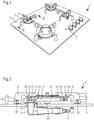
- a domestic gas cooking appliance 1 as illustrated with Fig. 1 comprises four gas burner assemblies 3 positioned on a worktop 5 approximately in a rectangular arrangement.
- the worktop 5 of the present example is made of glass ceramics, however, any other known material, such like a metal plate, may be used alternatively.
- the gas burner assemblies 3 work as fireplaces for the preparation of food, which preparation is usually performed using a cookware, for example a pot or a pan, placed on one of the gas burner assemblies 3.
- the operation of the gas burner assemblies 3 is controlled by means of control elements, which are rotary controls 7 in the present example.
- the four gas burner assemblies 3 are constructed similarly and mainly differ only in their dimensions, at least partially.
- Fig. 2 shows the gas burner assembly 3 arranged in the left rear position (in installation position) of the gas cooking appliance 1 in a cross-sectional view cut through a centre line of the gas burner assembly 3.
- Fig. 3 which shows the gas burner assembly 3 of Fig. 2 in an exploded view, the components and the construction of the gas burner assembly 3 are described as follows.
- the gas burner assembly 3 comprises a cookware support 9, a burner crown 11, a burner cap 13 and a burner body 15.
- the burner body 15 has a gas injector 17, which is connected (not shown) to a domestic gas supply system for a feed of gas to the gas burner assembly 3.
- the gas injector 17 feeds the gas jet to a horizontal Venturi tube 19 by way of injection.
- the Venturi tube 19 is adapted to mix the injected gas with primary air, thereby establishing a gas-air mixture.
- the cookware support 9 has four positioning foots 21, each one comprising a horizontally aligned arm portion 23 and a leg portion 25, which is integrally formed with the arm portion 23 by forming an angle of about 100 degrees. That way, the leg portions 25 are slightly inclined relative to the vertical, thereby contributing to a stable placement for cookware on the cookware support 9.
- the four positioning foots 21 are connected with each other to establish an arrangement roughly designed as a "+", however, without being directly connected with each other. That means, the free ends of the four positioning foots 21 are facing each other, but being distant from each other.
- the connection of the four positioning foots 21 is realized by means of an annular connection element 27.
- the upper surface of the annular connection element 27 is connected to the bottom side of the arm portion 23 of each positioning foot 21.
- the annular connection element 27 is integrally formed with the four positioning foots 21, wherein the one-piece cookware support 9 is produced by a die-casting process.
- the free end of the leg portion 25 of each positioning foot 21, forming a footprint of the cookware support 9, is equipped with a bumper element 29 made of a rubber or silicone material.
- the bumper element 29 has a connection pin 31 inserted in a mounting hole 33 of the positioning foot 21.
- the burner crown 11 is designed in an angular structure. In its cross section, the burner crown 11 is U-shaped forming a lower portion of an angular mixing chamber and/or gas feeding channel 43 and being adapted to feed the gas-air mixture to burner ports 41 of the burner crown 11. Since the gas burner assembly 3 of the present example is of a dual-burner type, said burner ports 41 are arranged in an inner and an outer ring wall of the burner crown providing gas passage directed both to the inward and to the outward. That way, gas combustion by generation of an inner and an outer flame ring is performed. The arrangement of the burner ports 41 is performed in a way equidistantly to each other, hence generating flame rings, which provide an even heat distribution.
- the burner cap 13 is also shaped annularly in alignment with the open top side of the burner crown 11.
- the burner cap 13 is fixed to the burner crown 11 by first fixation screws 47 passing through a hole in the burner cap 13 and screwed tightly into first screw holes 55 arranged in the burner crown 11.
- the burner body 15 is implemented in the gas cooking appliance 1 by a cup-shaped chamber 37 passing through a through hole 39 in the worktop 5.
- the cup-shaped chamber 37 is arranged downstream the Venturi tube 19 and an elbow connection between Venturi tube 19 and cup-shaped chamber 37.
- An end portion of the cup-shaped chamber 37 forms a gas outlet port 59 of the burner body 15.
- a gas inlet port 45 is arranged enabling the supply of the gas-air mixture established in the Venturi tube 19 and passed on by the cup-shaped chamber 37. Due to the annular shape of the burner crown 11, said gas inlet port 45 is arranged offset from a central axis of the burner crown 11.
- the assembly of burner crown 11 and burner cap 13 is coupled with the cookware support 9 by second fixation screws 49, thereby defining an upper burner portion 35.
- Said second fixation screws 49 are inserted in receiving through holes 51 from the bottom side of the burner crown 11.
- the second fixation screws 49 are not only passing through said receiving through holes 51 but also through burner cap through holes 53 in the burner cap 13 arranged in alignment with the receiving through holes 51.
- the second fixation screws 49 are finally screwed into second screw holes 57 being blind holes on the bottom side of the storage area of the cookware support 9.
- the second screw holes 49 are arranged also in alignment with the receiving through holes 51 and the burner cap through holes 53.
- the afore-mentioned coupling between the assembly of burner crown 11 and burner cap 13 to the cookware support 9 is not realized as a rigid connection. Rather, a limited and guided relative movement of the unit of burner crown 11 screwed together with the burner cap 13 in relation to the cookware support 9 is configured to perform a safe coupling between the gas outlet port 59 at the burner body 15 and the gas inlet port 45 at the burner crown 11 after placement of the upper burner portion 35 on the worktop 5 at its destination position. Due to said limited and guided relative movement tolerances of the whole gas burner assembly 3 and a potential uneven orientation of the worktop 5 can be compensated, resulting in an avoidance of gas leakage at all times and under all circumstances.
- Said guided movement is realized by the receiving through holes 51 forming guiding means for the shafts or the threaded bars of the second fixation screws 49, wherein the limited movement is realized by the heads of the second fixation screws 49 resting against allocated limit stops inside of the receiving through holes 51 in an end position of the guided movement.
- the gas outlet port 59 and the gas inlet port 45 comprise coupling means configured to establish said gastight connection.
- Said coupling means establish a labyrinth seal, which is performing the sealing after positioning the upper burner portion 35.
- An alternative solution to the labyrinth seal can also be an interaction between a conical outer surface of the gas inlet port 45 and a similarly conical inner surface of the cup-shaped chamber 37 and/or of the gas outlet port 59, said conical outer surface engaging said conical inner surface after placing the upper burner portion 35.
- the gas burner assembly 3 further comprises an igniter means 61 arranged on the top side of the burner body 15 and above the worktop 5.
- the ignitor means 61 is configured to spark the flame rings, particularly by providing an ignition spark by means of the allocated rotary control 7 operated with an axial push thereof.
Landscapes
- Engineering & Computer Science (AREA)
- Chemical & Material Sciences (AREA)
- Combustion & Propulsion (AREA)
- Mechanical Engineering (AREA)
- General Engineering & Computer Science (AREA)
- Gas Burners (AREA)
Abstract
Description
- The present invention relates to a gas burner assembly according to the preamble of claim 1. The present invention further relates to a household appliance, in particular a gas cooking appliance, comprising a gas burner assembly, according to claim 14.
- Gas burner assemblies are used in household cooking appliances for thermal treatment of food. Particularly for gas cooking hobs, gas burner assemblies are arranged on a worktop providing a fireplace for arranging a cookware thereon, which cookware is used to prepare the food therein. For a safe and solid placement of the cookware a cookware support is usually provided, which is positioned above the gas burner. For cleaning purposes, the cookware support and some components of the gas burner are separately removable from the worktop of the gas cooking appliance and after the cleaning process the components have to be re-assembled in reverse order.
- From
EP 2 589 879 A1 a gas burner assembly of a gas cooking hob is known, which comprises a burner crown that is attached to a bottom side of cookware support arms. A burner cap is fixed between the cookware support and the burner crown. Said arrangement of coupled burner crown, burner cap and cookware support can be jointly removed and put back into position in a single motion. After being put into position, a gas inlet flange projecting from the lower side of the burner crown is coupled to a gas outlet of the gas cooking hob. Said prior art gas burner assembly, however, is highly dependent on high dimensional accuracy, any tolerances between the involved components of the gas burner assembly as well as in relation to the worktop of the gas cooking hob result in gas leakages at the connection point between gas inlet flange and gas outlet or, on the other hand, in an instable placement of the cookware support on the worktop. - It is an object of the present invention to provide a gas burner assembly and/or a household appliance, with which tolerances present in a gas hob assembly, e.g. non-planarity of the worktop of the gas cooking hob, can be absorbed and the risk of gas leakages is avoided.
- The object is achieved for the gas burner assembly of the preamble of claim 1 according to the characterizing features of claim 1.
- A gas burner assembly, which may be used in a household appliance, particularly in a gas cooking appliance, comprises a burner body, a burner crown and a burner cap. The burner body has a gas outlet port and the burner crown has a gas inlet port, which is assignable to the gas outlet port of the burner body. The burner cap covers a top side of the burner crown. The arrangement of burner crown and burner cap defines a mixing chamber and/or gas feeding channel and is connected or connectable to a cookware support in a way to enable a joint or simultaneous handling, particularly a joint or simultaneous coupling with or decoupling from the burner body. According to the present invention, the gas burner assembly comprises adjustment means, which enable a relative movement, particularly a relative vertical movement, of the burner crown and/or the gas inlet port in relation to the cookware support.
- The core of the present invention is to provide a one-piece burner unit, particularly an upper burner portion, in terms of joint or simultaneous handling, which is capable of absorbing tolerances and insofar of avoiding gas leakages. Joint or simultaneous handling may be understood as an assembling, or positioning respectively, or disassembling from a worktop, for example in order to perform a cleaning process thereon.
- In particular, the gas outlet port of the burner body is aligned with the gas inlet port of the burner crown. The alignment is adjusted in a way allowing vertical gas flow. The alignment may further enable a vertically executed positioning and/or disassembling of the one piece burner unit, particularly the upper burner portion.
- The burner crown and/or the gas inlet port may be coupled with or connected to the cookware support by a first fixation means, wherein the coupling or connection allows a limited displacement of the burner crown and/or gas inlet port in relation to the cookware support. That means, said first fixation means may be configured to create a coupling without a rigid attachment, rather, at least one degree of freedom may be implemented in the system.
- Preferably, the first fixation means comprises at least one first screw or bolt. An end of said thread or bolt is fixed to the cookware support, preferably in a blind hole of the cookware support. A head of the first screw or bolt is configured to move in relation to the burner crown and/or the gas inlet port while the thread end or bolt end of the first screw or bolt is tightened or locked.
- According to embodiments, the head of the first screw or bolt is configured to move, in particular to move a limited distance, inside of a through hole arranged in the burner crown. In order not to enable unlimited movement, the through hole preferably comprises a limit stop for the head of the first screw or bolt. Said limit stop may be configured to arrange for the screw head resting thereon in an end position of said relative movement. In particular, the through hole arranged in the burner crown may be formed as a first portion of the through hole with a bigger diameter, in which the screw head is movable, and a second portion of the through hole with a smaller diameter, which the screw head cannot enter. In that specific solution of the through hole, a step or collar is established at the transition between first and second portions, which step or collar forming a limit stop for the screw head.
- A specific embodiment is characterized in that the burner crown and burner cap comprise at least one pair of corresponding through holes which are slidably penetrated by a shaft or thread of the first screw or bolt. In the above-mentioned case of the through hole of the burner crown with two portions with different diameters, the through hole of the burner cap may be arranged or arrangeable adjacent to the portion with the smaller diameter.
- An alternative or additional solution to the above-described slidable screw head may be considered as well, being a support to or a replacement for this solution. Said alternative or additional solution is in particular a coupling of the assembly of burner crown and burner cap with the cookware support by means of or comprising a telescopic guidance, for example a telescopic tube or the like, and/or by means of or comprising a spring balancer. Such kinds of alternative or additional solutions may also be characterized by a limit stop or any other type of movement limitation.
- The burner cap may be fixedly attached to the burner crown by use of a second fixation means, preferably by use of at least one second screw or bolt. Said at least one second screw may be configured to be completely screwed in, so that its screw head locks the burner cap tightly to the burner crown. In that specific solution, a screw hole with a sufficient depth leaving unfilled space after tightening the second fixation means is favourable.
- An even cheaper solution for the coupling between burner crown and burner cap may be found by omitting the use of the second fixation means. Said solution may provide for the burner cap just being laid down on the upper side of the burner crown. That way, the burner cap is kept in position by its weight force. In addition, in order to avoid a slipping of the burner cap and getting out of its correct place, bordering means, particularly lateral bordering means, may be provided.
- In particular, the gas inlet port of the burner crown is configured to be set in gastight operative connection with the gas outlet port of the burner body. The gas outlet port and the gas inlet port preferably comprise coupling means configured to establish said gastight connection.
- The coupling means between the gas outlet port and the gas inlet port may comprise a labyrinth seal. Additionally or alternatively, a flat seal arrangement may be provided by a flat lower annular surface of the burner crown, which rests on a flat upper annular surface of the burner body. Said labyrinth seal is preferably configured to establish the gastight connection by simply positioning the specific upper burner portion on its dedicated position, characterized by the allocation of the gas inlet port of the burner crown to the gas outlet port of the burner body.
- An alternative solution to the labyrinth seal may be a joining of a conical gas inlet port and a similarly conical gas outlet port, which fit together by a custom-fit coupling when the upper burner portion is positioned. Another alternative solution may be a provision of a gasket, preferably a high temperature gasket, between the burner crown and the burner body.
- Preferably, the cookware support comprises at least three, preferably four, support arms as well as support legs assigned to the support arms, particularly a related number of support legs, which means that each support leg may be connected to a dedicated support arm. Each one of the support legs may comprise a support surface at its free end, which support surface preferably being equipped with an elastic layer.
- A specifically preferred solution is characterized in that the cookware support is made by cast iron. Preferably, it is produced in a single manufacturing step, in particular by using a single mould.
- The mixing chamber and/or gas feeding channel defined by the burner crown and the burner cap is favourably a sealed channel or sealed chamber, which is formed annularly.
- According to a specific embodiment, the gas inlet port of the burner crown is arranged offset from a central axis of the burner crown. The burner crown is preferably of a dual-burner type, which generates an inner and an outer flame ring. The flames of the inner flame ring comprise a directional component oriented radially inwards, i.e. towards the central axis of the burner crown, while the flames of the outer flame ring are directed outwards.
- One specific embodiment is characterized by a burner crown, which is made of an aluminium material, preferably manufactured by a die-casting process. Additionally or alternatively, the specific embodiment comprises a burner cap, which is made of steel, preferably manufactured by stamping. A further specific embodiment may, also additionally or alternatively, provide a cookware support, which is made of cast iron.
- Further, the object is achieved for a household appliance according to claim 14.
- According to a further aspect of the invention, a household appliance, in particular a gas cooking appliance, is provided, which comprises at least one gas burner assembly according to anyone of the above-described embodiments.
- A specific embodiment of the household appliance further comprises a horizontal worktop for the placement of the gas burner assembly. The burner body of said gas burner assembly comprises a gas injection means and particularly a horizontal Venturi tube arranged below the bottom side of the worktop. The gas outlet port of the burner body is accessible from above through a cut-out or through hole in the worktop. Said access may be provided above the top side of the worktop.
- Novel and inventive features of the present invention are set forth in the appended claims.
- The present invention will be described in further detail with reference to the drawing, in which
- Fig. 1
- illustrates a domestic gas cooking appliance comprising four gas burner assemblies in a perspective view,
- Fig. 2
- is a cross-sectional view through the gas cooking appliance of
Fig. 1 along the line II - II illustrating one of the gas burner assemblies, and - Fig. 3
- illustrates the gas burner assembly of
Fig. 2 in the cross-sectional view according toFig. 2 , but in an exploded view. - A domestic gas cooking appliance 1 as illustrated with
Fig. 1 comprises fourgas burner assemblies 3 positioned on aworktop 5 approximately in a rectangular arrangement. Theworktop 5 of the present example is made of glass ceramics, however, any other known material, such like a metal plate, may be used alternatively. When operated, thegas burner assemblies 3 work as fireplaces for the preparation of food, which preparation is usually performed using a cookware, for example a pot or a pan, placed on one of thegas burner assemblies 3. The operation of thegas burner assemblies 3 is controlled by means of control elements, which are rotary controls 7 in the present example. - The four
gas burner assemblies 3 are constructed similarly and mainly differ only in their dimensions, at least partially. By way of illustration,Fig. 2 shows thegas burner assembly 3 arranged in the left rear position (in installation position) of the gas cooking appliance 1 in a cross-sectional view cut through a centre line of thegas burner assembly 3. With reference toFig. 2 as well as toFig. 3 , which shows thegas burner assembly 3 ofFig. 2 in an exploded view, the components and the construction of thegas burner assembly 3 are described as follows. - The
gas burner assembly 3 comprises acookware support 9, aburner crown 11, aburner cap 13 and aburner body 15. Theburner body 15 has agas injector 17, which is connected (not shown) to a domestic gas supply system for a feed of gas to thegas burner assembly 3. Thegas injector 17 feeds the gas jet to ahorizontal Venturi tube 19 by way of injection. TheVenturi tube 19 is adapted to mix the injected gas with primary air, thereby establishing a gas-air mixture. - The
cookware support 9 has four positioning foots 21, each one comprising a horizontally alignedarm portion 23 and aleg portion 25, which is integrally formed with thearm portion 23 by forming an angle of about 100 degrees. That way, theleg portions 25 are slightly inclined relative to the vertical, thereby contributing to a stable placement for cookware on thecookware support 9. - The four positioning foots 21 are connected with each other to establish an arrangement roughly designed as a "+", however, without being directly connected with each other. That means, the free ends of the four positioning foots 21 are facing each other, but being distant from each other. The connection of the four positioning foots 21 is realized by means of an
annular connection element 27. The upper surface of theannular connection element 27 is connected to the bottom side of thearm portion 23 of each positioningfoot 21. Theannular connection element 27 is integrally formed with the four positioning foots 21, wherein the one-piece cookware support 9 is produced by a die-casting process. - The free end of the
leg portion 25 of each positioningfoot 21, forming a footprint of thecookware support 9, is equipped with abumper element 29 made of a rubber or silicone material. Thebumper element 29 has aconnection pin 31 inserted in a mountinghole 33 of thepositioning foot 21. - The
burner crown 11 is designed in an angular structure. In its cross section, theburner crown 11 is U-shaped forming a lower portion of an angular mixing chamber and/orgas feeding channel 43 and being adapted to feed the gas-air mixture toburner ports 41 of theburner crown 11. Since thegas burner assembly 3 of the present example is of a dual-burner type, saidburner ports 41 are arranged in an inner and an outer ring wall of the burner crown providing gas passage directed both to the inward and to the outward. That way, gas combustion by generation of an inner and an outer flame ring is performed. The arrangement of theburner ports 41 is performed in a way equidistantly to each other, hence generating flame rings, which provide an even heat distribution. - In order to build up a mixing chamber and/or
gas feeding channel 43 closed on its top side, theburner cap 13 is also shaped annularly in alignment with the open top side of theburner crown 11. Theburner cap 13 is fixed to theburner crown 11 by first fixation screws 47 passing through a hole in theburner cap 13 and screwed tightly into first screw holes 55 arranged in theburner crown 11. - The
burner body 15 is implemented in the gas cooking appliance 1 by a cup-shapedchamber 37 passing through a throughhole 39 in theworktop 5. The cup-shapedchamber 37 is arranged downstream theVenturi tube 19 and an elbow connection betweenVenturi tube 19 and cup-shapedchamber 37. An end portion of the cup-shapedchamber 37 forms agas outlet port 59 of theburner body 15. - At the bottom side of the
burner crown 11 agas inlet port 45 is arranged enabling the supply of the gas-air mixture established in theVenturi tube 19 and passed on by the cup-shapedchamber 37. Due to the annular shape of theburner crown 11, saidgas inlet port 45 is arranged offset from a central axis of theburner crown 11. - The assembly of
burner crown 11 andburner cap 13 is coupled with thecookware support 9 by second fixation screws 49, thereby defining anupper burner portion 35. Said second fixation screws 49 are inserted in receiving throughholes 51 from the bottom side of theburner crown 11. The second fixation screws 49 are not only passing through said receiving throughholes 51 but also through burner cap throughholes 53 in theburner cap 13 arranged in alignment with the receiving throughholes 51. The second fixation screws 49 are finally screwed into second screw holes 57 being blind holes on the bottom side of the storage area of thecookware support 9. The second screw holes 49 are arranged also in alignment with the receiving throughholes 51 and the burner cap throughholes 53. For a safe coupling between the assembly ofburner crown 11 andburner cap 13 to thecookware support 9, a relevant screw-in depth is provided, which is realized in that said second screw holes 57 are arranged in the connection areas betweenconnection element 27 and positioning foots 21. - The afore-mentioned coupling between the assembly of
burner crown 11 andburner cap 13 to thecookware support 9 is not realized as a rigid connection. Rather, a limited and guided relative movement of the unit ofburner crown 11 screwed together with theburner cap 13 in relation to thecookware support 9 is configured to perform a safe coupling between thegas outlet port 59 at theburner body 15 and thegas inlet port 45 at theburner crown 11 after placement of theupper burner portion 35 on theworktop 5 at its destination position. Due to said limited and guided relative movement tolerances of the wholegas burner assembly 3 and a potential uneven orientation of theworktop 5 can be compensated, resulting in an avoidance of gas leakage at all times and under all circumstances. - Said guided movement is realized by the receiving through
holes 51 forming guiding means for the shafts or the threaded bars of the second fixation screws 49, wherein the limited movement is realized by the heads of the second fixation screws 49 resting against allocated limit stops inside of the receiving throughholes 51 in an end position of the guided movement. - By attaching the
burner crown 11 and theburner cap 13 to thecookware support 9 with forming saidupper burner portion 35, these three elements can be handled as a one-piece part. Hence, if theupper burner portion 35 has to be removed from the gas cooking appliance 1, theupper burner portion 35 can be taken away in a single motion. It is not required to remove individual parts of a gas burner unit from the gas cooking appliance 1. Similarly, if theupper burner portion 35 has to be placed on the gas cooking appliance 1 again, it can be placed and positioned in a single motion. Coincidently, the coupling of theupper burner portion 35 with theburner body 15 is realized by avoiding gas leakages, at all times and under all circumstances as mentioned above. - In order to further support gastight connection, the
gas outlet port 59 and thegas inlet port 45 comprise coupling means configured to establish said gastight connection. Said coupling means establish a labyrinth seal, which is performing the sealing after positioning theupper burner portion 35. An alternative solution to the labyrinth seal can also be an interaction between a conical outer surface of thegas inlet port 45 and a similarly conical inner surface of the cup-shapedchamber 37 and/or of thegas outlet port 59, said conical outer surface engaging said conical inner surface after placing theupper burner portion 35. Another contribution to a sealed connection is provided by a flat lowerannular surface 11a arranged around thegas inlet port 45 of theburner crown 11 resting a flat upperannular surface 15a arranged around thegas outlet port 59 of theburner body 15, thereby forming a flat seal arrangement. - The
gas burner assembly 3 further comprises an igniter means 61 arranged on the top side of theburner body 15 and above theworktop 5. The ignitor means 61 is configured to spark the flame rings, particularly by providing an ignition spark by means of the allocated rotary control 7 operated with an axial push thereof. -
- 1
- gas cooking appliance
- 3
- gas burner assembly
- 5
- worktop
- 7
- rotary control
- 9
- cookware support
- 11
- burner crown
- 11a
- lower annular surface
- 13
- burner cap
- 15
- burner body
- 15a
- upper annular surface
- 17
- gas injector
- 19
- Venturi tube
- 21
- positioning foot
- 23
- arm portion
- 25
- leg portion
- 27
- connection element
- 29
- bumper element
- 31
- connection pin
- 33
- mounting hole
- 35
- upper burner portion
- 37
- cup-shaped chamber
- 39
- worktop through hole
- 41
- burner port
- 43
- mixing chamber / gas feeding channel
- 45
- gas inlet port
- 47
- first fixation screw
- 49
- second fixation screw
- 51
- receiving through hole
- 53
- burner cap through hole
- 55
- first screw hole
- 57
- second screw hole
- 59
- gas outlet port
- 61
- ignitor means
Claims (15)
- A gas burner assembly (3), particularly for a household appliance, more particularly for a gas cooking appliance (1), the gas burner assembly (3) comprising- a burner body (15) having a gas outlet port (59),- a burner crown (11) having a gas inlet port (45) assignable to the gas outlet port (59) of the burner body (15), and- a burner cap (13) covering a top side of the burner crown (11),the arrangement of burner crown (11) and burner cap (13) defining a mixing chamber and/or gas feeding channel (43) and being connected or connectable to a cookware support (9) in a way to enable a joint or simultaneous handling, particularly a joint or simultaneous coupling with or decoupling from the burner body (15),
characterized by
adjustment means (49, 51, 57), enabling a relative movement, particularly a relative vertical movement, of the burner crown (11) and/or of the gas inlet port (45) in relation to the cookware support (9). - The gas burner assembly (3) according to claim 1,
characterized in that
the gas outlet port (59) of the burner body (15) is aligned with the gas inlet port (45) of the burner crown (11), the alignment allowing vertical gas flow. - The gas burner assembly (3) according to claim 1 or 2,
characterized in that
the burner crown (11) and/or the gas inlet port (45) is/are coupled with or connected to the cookware support (9) by a first fixation means (49), wherein the coupling or connection allows a limited displacement of the burner crown (11) and/or of the gas inlet port (45) in relation to the cookware support (9). - The gas burner assembly (3) according to claim 3,
characterized in that
the first fixation means (49) comprises at least one first screw (49) or bolt, a thread end or bolt end thereof being fixed to the cookware support (9), preferably in a blind hole (57) of the cookware support (9), wherein a head of the first screw (49) or bolt is configured to move in relation to the burner crown (11) and/or gas inlet port (45) while the thread end or bolt end of the first screw (49) or bolt is tightened or locked. - The gas burner assembly (3) according to claim 4,
characterized in that
the head of the first screw (49) or bolt is configured to move, in particular to move a limited distance, inside of a receiving through hole (51) arranged in the burner crown (11), wherein the receiving through hole (51) preferably comprises a limit stop for the head of the first screw (49) or bolt. - The gas burner assembly (3) according to claim 4 or 5,
characterized in that
the burner crown (11) and burner cap (13) comprise at least one pair of corresponding through holes (51, 53), which are slidably penetrated by a shaft or thread of the first screw (49) or bolt. - The gas burner assembly (3) according to anyone of the preceding claims,
characterized in that
the burner cap (13) is fixedly attached to the burner crown (11) by means of a second fixation means (47), preferably by means of at least one second screw (47) or bolt. - The gas burner assembly (3) according to anyone of the preceding claims,
characterized in that
the gas inlet port (45) of the burner crown (11) is configured to be set in gastight operative connection with the gas outlet port (59) of the burner body (15), the gas outlet port (59) and the gas inlet port (45) preferably comprising coupling means configured to establish said gastight connection. - The gas burner assembly (3) according to claim 8,
characterized in that
the coupling means between gas outlet port (59) and gas inlet port (45) comprise a labyrinth seal and/or a flat lower annular surface (11a) of the burner crown (11) resting a flat upper annular surface (15a) of the burner body (15), thereby forming a flat seal arrangement. - The gas burner assembly (3) according to anyone of the preceding claims,
characterized in that
the cookware support (9) comprises at least three, preferably four, support arms (23) as well as at least three, preferably four, support legs (25) assigned to the support arms (23), each one of the support legs (25) comprising a support surface, which support surface preferably being equipped with an elastic layer (29). - The gas burner assembly according to anyone of the preceding claims,
characterized in that
the mixing chamber and/or gas feeding channel (43) is a sealed channel or sealed chamber, which is formed annularly. - The gas burner assembly (3) according to claim 11,
characterized in that
the gas inlet port (45) of the burner crown (11) is arranged offset from a central axis of the burner crown (11), the burner crown (11) preferably generating an inner and an outer flame ring. - The gas burner assembly (3) according to anyone of the preceding claims,
characterized in that
the burner crown (11) is made of an aluminium material, preferably manufactured by a die-casting process,
and/or
the burner cap (13) is made of steel, preferably manufactured by stamping,
and/or
the cookware support (9) is made of cast iron. - A household appliance, in particular a gas cooking appliance (1), comprising
at least one gas burner assembly (3) according to anyone of the preceding claims. - The household appliance according to claim 14,
further comprising
a horizontal worktop (5) for the placement of the gas burner assembly (3), wherein the burner body (15) of the gas burner assembly (3) comprises a gas injection means (17,) and particularly a horizontal Venturi tube (19), arranged below the bottom side of the worktop (5), and wherein the gas outlet port (59) of the burner body (15) is accessible from above through a cut-out or through hole (37) in the worktop (5), preferably above the top side of the worktop (5).
Priority Applications (2)
| Application Number | Priority Date | Filing Date | Title |
|---|---|---|---|
| EP20197350.0A EP3971479A1 (en) | 2020-09-22 | 2020-09-22 | Gas burner assembly and household appliance comprising a gas burner assembly |
| PCT/EP2021/071947 WO2022063473A1 (en) | 2020-09-22 | 2021-08-05 | Gas burner assembly and household appliance comprising a gas burner assembly |
Applications Claiming Priority (1)
| Application Number | Priority Date | Filing Date | Title |
|---|---|---|---|
| EP20197350.0A EP3971479A1 (en) | 2020-09-22 | 2020-09-22 | Gas burner assembly and household appliance comprising a gas burner assembly |
Publications (1)
| Publication Number | Publication Date |
|---|---|
| EP3971479A1 true EP3971479A1 (en) | 2022-03-23 |
Family
ID=72613861
Family Applications (1)
| Application Number | Title | Priority Date | Filing Date |
|---|---|---|---|
| EP20197350.0A Withdrawn EP3971479A1 (en) | 2020-09-22 | 2020-09-22 | Gas burner assembly and household appliance comprising a gas burner assembly |
Country Status (2)
| Country | Link |
|---|---|
| EP (1) | EP3971479A1 (en) |
| WO (1) | WO2022063473A1 (en) |
Citations (6)
| Publication number | Priority date | Publication date | Assignee | Title |
|---|---|---|---|---|
| GB184334A (en) * | 1921-06-28 | 1922-08-17 | Charles Stephen Barnes | Improvements in or relating to gas burners for heating and cooking purposes |
| GB968296A (en) * | 1962-04-19 | 1964-09-02 | Sidney Flavel & Co Ltd | Pan supports for gas-heated cooking appliances |
| WO2013017986A2 (en) * | 2011-07-29 | 2013-02-07 | Indesit Company S.P.A. | Gas burner, in particular for a food cooking appliance |
| EP2589879A1 (en) | 2011-11-04 | 2013-05-08 | Electrolux Home Products Corporation N.V. | Gas burner assembly, gas cooking hob and gas burner appliance |
| EP3546833A1 (en) * | 2018-03-26 | 2019-10-02 | Electrolux Appliances Aktiebolag | Gas cooking assembly and a hob comprising the same |
| US20200182458A1 (en) * | 2018-12-07 | 2020-06-11 | Bsh Home Appliances Corporation | Gas cooking grate with integral burner |
-
2020
- 2020-09-22 EP EP20197350.0A patent/EP3971479A1/en not_active Withdrawn
-
2021
- 2021-08-05 WO PCT/EP2021/071947 patent/WO2022063473A1/en not_active Ceased
Patent Citations (7)
| Publication number | Priority date | Publication date | Assignee | Title |
|---|---|---|---|---|
| GB184334A (en) * | 1921-06-28 | 1922-08-17 | Charles Stephen Barnes | Improvements in or relating to gas burners for heating and cooking purposes |
| GB968296A (en) * | 1962-04-19 | 1964-09-02 | Sidney Flavel & Co Ltd | Pan supports for gas-heated cooking appliances |
| WO2013017986A2 (en) * | 2011-07-29 | 2013-02-07 | Indesit Company S.P.A. | Gas burner, in particular for a food cooking appliance |
| EP2589879A1 (en) | 2011-11-04 | 2013-05-08 | Electrolux Home Products Corporation N.V. | Gas burner assembly, gas cooking hob and gas burner appliance |
| EP2589879B1 (en) * | 2011-11-04 | 2017-01-11 | Electrolux Home Products Corporation N.V. | Gas burner assembly, gas cooking hob and gas burner appliance |
| EP3546833A1 (en) * | 2018-03-26 | 2019-10-02 | Electrolux Appliances Aktiebolag | Gas cooking assembly and a hob comprising the same |
| US20200182458A1 (en) * | 2018-12-07 | 2020-06-11 | Bsh Home Appliances Corporation | Gas cooking grate with integral burner |
Also Published As
| Publication number | Publication date |
|---|---|
| WO2022063473A1 (en) | 2022-03-31 |
Similar Documents
| Publication | Publication Date | Title |
|---|---|---|
| EP1838997B1 (en) | Gas burner for cooking appliances | |
| US8689779B2 (en) | Gas burner | |
| EP2226560A2 (en) | Burner with multiple flame rings for ranges | |
| NZ588231A (en) | Accomodation of expansion in burner assembly of gas cooker | |
| AU2016218155B2 (en) | A gas burner assembly | |
| WO2012144265A1 (en) | Burner for stove | |
| EP1459012B1 (en) | Gas burner with several flame sectors | |
| CN212869872U (en) | Three-ring fire stove burner with double injection pipes | |
| CN109959007B (en) | Burner fire cover for gas stove and burner using same | |
| TWI797355B (en) | Burners for gas stoves and gas stoves | |
| WO2022063473A1 (en) | Gas burner assembly and household appliance comprising a gas burner assembly | |
| CN220892243U (en) | Burner assembly and stove | |
| CN220892242U (en) | Burner and kitchen range | |
| CN111006213B (en) | Burner and gas stove | |
| CN114562745B (en) | A stove installation structure and cooking appliance thereof | |
| CN119713268B (en) | Burners and stoves | |
| CN119713269B (en) | Burner assembly and stove | |
| GB2545323A (en) | Cooking hob gas burner | |
| CN215597342U (en) | Dry burning prevention sensor mounting structure for stove and stove | |
| CN222363885U (en) | Burner and kitchen range | |
| CN219889554U (en) | Top air inlet type gas stove cooking range assembly and gas stove | |
| CN119042628B (en) | Burner and stove | |
| US20250164106A1 (en) | Inward fired radial gas burner assembly and cooktop appliance | |
| US20250164107A1 (en) | Inward fired radial gas burner assembly for cooktop appliance and method for fabrication | |
| CN116817273B (en) | Top air inlet type gas stove cooking range assembly and gas stove |
Legal Events
| Date | Code | Title | Description |
|---|---|---|---|
| PUAI | Public reference made under article 153(3) epc to a published international application that has entered the european phase |
Free format text: ORIGINAL CODE: 0009012 |
|
| STAA | Information on the status of an ep patent application or granted ep patent |
Free format text: STATUS: THE APPLICATION HAS BEEN PUBLISHED |
|
| AK | Designated contracting states |
Kind code of ref document: A1 Designated state(s): AL AT BE BG CH CY CZ DE DK EE ES FI FR GB GR HR HU IE IS IT LI LT LU LV MC MK MT NL NO PL PT RO RS SE SI SK SM TR |
|
| STAA | Information on the status of an ep patent application or granted ep patent |
Free format text: STATUS: REQUEST FOR EXAMINATION WAS MADE |
|
| 17P | Request for examination filed |
Effective date: 20220923 |
|
| RBV | Designated contracting states (corrected) |
Designated state(s): AL AT BE BG CH CY CZ DE DK EE ES FI FR GB GR HR HU IE IS IT LI LT LU LV MC MK MT NL NO PL PT RO RS SE SI SK SM TR |
|
| GRAP | Despatch of communication of intention to grant a patent |
Free format text: ORIGINAL CODE: EPIDOSNIGR1 |
|
| STAA | Information on the status of an ep patent application or granted ep patent |
Free format text: STATUS: GRANT OF PATENT IS INTENDED |
|
| INTG | Intention to grant announced |
Effective date: 20230531 |
|
| STAA | Information on the status of an ep patent application or granted ep patent |
Free format text: STATUS: THE APPLICATION IS DEEMED TO BE WITHDRAWN |
|
| 18D | Application deemed to be withdrawn |
Effective date: 20231011 |