EP2226560A2 - Burner with multiple flame rings for ranges - Google Patents
Burner with multiple flame rings for ranges Download PDFInfo
- Publication number
- EP2226560A2 EP2226560A2 EP09179437A EP09179437A EP2226560A2 EP 2226560 A2 EP2226560 A2 EP 2226560A2 EP 09179437 A EP09179437 A EP 09179437A EP 09179437 A EP09179437 A EP 09179437A EP 2226560 A2 EP2226560 A2 EP 2226560A2
- Authority
- EP
- European Patent Office
- Prior art keywords
- flame crown
- crown
- mentioned
- grooves
- small
- Prior art date
- Legal status (The legal status is an assumption and is not a legal conclusion. Google has not performed a legal analysis and makes no representation as to the accuracy of the status listed.)
- Withdrawn
Links
Images


Classifications
-
- F—MECHANICAL ENGINEERING; LIGHTING; HEATING; WEAPONS; BLASTING
- F23—COMBUSTION APPARATUS; COMBUSTION PROCESSES
- F23D—BURNERS
- F23D14/00—Burners for combustion of a gas, e.g. of a gas stored under pressure as a liquid
- F23D14/02—Premix gas burners, i.e. in which gaseous fuel is mixed with combustion air upstream of the combustion zone
- F23D14/04—Premix gas burners, i.e. in which gaseous fuel is mixed with combustion air upstream of the combustion zone induction type, e.g. Bunsen burner
- F23D14/06—Premix gas burners, i.e. in which gaseous fuel is mixed with combustion air upstream of the combustion zone induction type, e.g. Bunsen burner with radial outlets at the burner head
-
- F—MECHANICAL ENGINEERING; LIGHTING; HEATING; WEAPONS; BLASTING
- F23—COMBUSTION APPARATUS; COMBUSTION PROCESSES
- F23D—BURNERS
- F23D14/00—Burners for combustion of a gas, e.g. of a gas stored under pressure as a liquid
- F23D14/46—Details, e.g. noise reduction means
- F23D14/62—Mixing devices; Mixing tubes
- F23D14/64—Mixing devices; Mixing tubes with injectors
-
- F—MECHANICAL ENGINEERING; LIGHTING; HEATING; WEAPONS; BLASTING
- F23—COMBUSTION APPARATUS; COMBUSTION PROCESSES
- F23D—BURNERS
- F23D2900/00—Special features of, or arrangements for burners using fluid fuels or solid fuels suspended in a carrier gas
- F23D2900/14—Special features of gas burners
- F23D2900/14062—Special features of gas burners for cooking ranges having multiple flame rings
Definitions
- Another specification of the invention is that the distance between surface(4.3) at the end of the bore (4.3) that created vertical venturi effect in big flame crown (4) after small flame crown (3) is mounted to big flame crown (4) and bottom surface (3.3) located at small flame crown (3) and creates horizontal venturi effect is between 1 and 10 mm preferably around 2.5 mm.
- Another specification of the invention is the burning may be increased or decreased in small flame crown (3) by changing diameter of the ports of small flame crown (3). This change may only be possible by changing small flame crown (3).
- the invention is convenient to be used in all places where these type multi burners are used currently. Particularly it is convenient to be used in household cookers.
Abstract
Description
- It is the multi-burning system mountable to domestic gas cooking appliances used in houses and provides homogeneous heating of cooker placed on it. This burning system provides homogeneous distribution of flame by burning so as ring with three or four levels. There are one or two inner ring burning and one and two outer ring burning according to the burning system. The flow rate of gas is regulated by means of a gas valve and thus the control of inner ring and outer ring are made. The burner systems used in currently used ovens or cookers sing burning system is used. Totally three different burnings as small, medium and large are provided on oven or cooker in three different burner. Besides them also burners those accommodates two or three burning systems inside them are started to be used. These burners those accommodate two types of burning inside them are usually accommodate small and large burner inside of them simultaneously: These burners are separated as power systems 2.5 kW, 3.6 Kw, 3.8 kW, 4.5kW and 5kW generally. But it is required to send air and gas mixture with correct ratio to the ports of the burner by designing each of these burners separately in order to obtain this power.
- The burners those have this type one inner ring and one outer ring burning system have been used in Far East countries for many years. But this type of burning systems used in the Far East countries do not provide excessive control. A mixing chamber is implemented to these types of systems today and they took their current modern form. In case of to talk on technical space in the operation of the system requires, one or more inlet provides air entrance and this primary air mixes with gas in a mixing chamber this is carried to burning chambers by venturi effect. The air - gas mixture those come out through burning ports are provided to burn by a means of ignition. For continuity of burning secondary air drawn out of the environment during burning.
- At the same in order to be able to mount such type or similar burners to cooker or oven they need to have same mechanical connections. Since oven producer places holes and connection points on the iron sheet placed on the iron sheet according to this. If it is needed to give a simple example to this, the centers of the ears those are called as ear in which thread is opened and the center of bore of bored place located on the top iron sheet of the oven and to which this burner will be attached are same. Therefore, burner producers keep these connection points fixed while they are making designs. If these connection points are changed, oven producers may not use them.
- Burners for ovens or cookers those equipped two or more gas head exist so as known burners those have three heads one of them looks at inside and two of them looks outer side of the cooker.
- There is a patent application with patent number
GB2233444 - However the above mentioned structure unfortunately is not quite convenient to use in side supplements of gas cookers. The reason of this is the low profiles of these burners those do not allow the use of long grooves those mix gas and air mixture. Furthermore, peripheral flame crown oriented to inner side will have lesser flame. Also the reason of this is the burning problem in this type of burners resulted from interferences of crowns of which their opposite surfaces facing each other to each other.
- There is patent application with patent number
WO 2007007298 (A2) on 13th July 2006 recorded in the name of Bek Metal Enjeksiyon San. Ve Tic. Ltd. Sti.. The said patent application is related with burners those are used in gas cookers and have multi flame crown. A chamber cover that is developed and can be easily removed and attached is mentioned in the said invention. The said cover is shown withfigure 4 in the invention. This chamber cover placed in the system causes cost overrun in these type products and it may hinder the arrival of air gas mixture homogeneously in case of this cover gets loose in the system. - Also it is asserted that there is a burner that ensures the protection of impurities to skip in injector inlet by closing the top of the injector that provides gas entrance and prevention of blockages those may occur by means of this. But the cover that closes the top of the injector is not connected to the system mechanically. It is quite difficult to prevent entrance of impurities between this kind of a cover that does not connected mechanically and is left idle in the system. Since cleaning agents of this type of system are composed of very small particles and liquids. As it is known liquids and very small particles may move from the smallest emptiness that they find and they may pass from the smallest emptiness in the system. In this sense the invention cannot solve the problem absolutely
- The solution of the technical problem explained in above can be possible with the burner that is our invention. The above mentioned patent application does not cover our invention although it constitutes a technical infrastructure to our invention. Gas - air mixture does not come out from a middle point and this zone is closed. Therefore, it s impossible any substance that enters from outside to block gas outlet and gas exit points. Also housewives of today have difficulty in cleaning of this kind of systems. Because the design structure of burners those have multi-burning system is quite complex. Therefore, dismantling these burners is quite hard.
- In the patent application recorded in the name of SABAF SPA (IT) on 24th June 1997 with patent number
EP 0797048 (A1 ), a burner is mentioned with a central flame ring, two co-central circular crown, basically a horizontal venturi effect chamber and bore or grooves for providing air and gas from venturi chamber to central crown for gas cooking appliances. The said patent said that the total vertical height of the burner is reduced relative to the previous one. But the height of circular crown that provides small burning and located in the middle of cylindrical head shown withfigure 16 is reduced. In the said invention the secondary air that was given from the bottom was insufficient and at the same time a secondary air feeding is required from a second place. Therefore, the crown at the middle part is raised a little more. - The patent application dated 23rd January 1004 with number
WO2005080870 A1 recorded in the name of BURNER SYSTEM INTERNATIONAL(BSI) is related with a burner head that has a peripheral crown and carries burning head that is fed by radial grooves extended from the said central head fed by a central orifice for gas cooking appliances. In the mentioned system wastes those come from outside to burner cup that carries the burning head and that is shown byfigure 1 may be very easy and the burning of the system may be affected by time because of central head in the middle is fed through an orifice.
Also the said radial grooves may become dirty in time and air-gas mixture may not be fed in the desired efficiency within the system. Also the said central head is located very high relative to peripheral crown and therefore, total vertical height of burner is increased. This also causes higher cooker production of cooker producers. Thus the invention is not an economic solution. - The solution of the technical problem explained in above can be possible with the burner that is our invention. The above mentioned patent application does not cover our invention although it constitutes a technical infrastructure to our invention. This vertical height can be drawn to lower heights as per the requirement of the design of our invention and secondary air quantity that comes through cooker and burner to middle crown section is increased. The design of our invention allows this. Therefore, our invention is exceeded the known state of art and contains innovation.
- In the patent application in June 2001 with number
EP1297281 (A1 ) recorded in the name of SABAF SPA [IT] a burner is explained that covers minimum two gas heads minimum a circular one, a mixing chamber that carries venturi effect, grooves for incoming primary air to minimum one of the mentioned circular head, a house, a head and the grooves for enterance of primary air that contains radial grooves for feeding gas/primary air and a seperationdividing into grooves component for distribution of gas/primary air. The part that separates air-gas mixture and primary air is called byfigure 4 in the said invention. This part mentioned in the invention separates primary air and air gas mixture by connecting with screws those are mechanical connection components or with the help of deformed pins by forging. However, in case of the mentioned part withfigure 4 is connected to system by using a connection component such as screw, the leakages may connection points and this also may effect the efficiency of the system negatively. The connection with screw is not an ideal solution. On the hand in case of part deformed by forging is used the small leakages may be prevented but in this case it is impossible to adjust defective manufacturing. This also may open way time and cost lose in serious sense. Also a burner's that is connected to the system in the shape of cross by the help of screws or pins deformed by forging groves through which primary air and gas/primary air pass may be blocked in a very short period. This groove cannot be cleaned fully since housewives cannot dismantle this part shown withnumber 4 and this causes the blockage of them in the future. - In the patent application dated
9th January 1998 with patent number WO9830838 A1
In the patent application in July 1994 with patent numberEP0634608 A2 recorded in the name ofDEFENDI OFF MEC 10 SRL [IT] a burner having multi-pieces that contains flame outlets from two surfaces and radial grooves that will connect these outlets are explained. This invention is composed of five components. The production of this burner which operates with injector holder system is difficult and costly. - The patent application dated
23rd September 1997 with patent number EP0903538 A1 recorded in the name of SABAF SPA [IT] contains a central flame crown and two peripheral flame crowns. There is a horizontal venture chamber formed between house and flame cover in this burner. However the said burner has many disadvantages besides its advantages. Since the venturi effect is formed between the house and flame cover the geometric form of the cover that will create this effect has great importance and it increase the cost of production. This venture effect if formed by the flame cove that is produced for this burner only and use of similar covers are not possible. Again this venture effect is affected negatively in any deformation that will be formed in the said cover. The open top of the injector that provides gas to the chamber in which venturi effect is formed and during cleaning of the burner some impurities may run inside may cause blockages. - Consequently the existence of the need for multi-burners those eliminate the disadvantages of multi-burners in the current technology and insufficiency of available solutions require to make a development in the related technological area.
- The purpose of the invention is to develop a burner that uses both horizontal and vertical venturi effect and provides homogeneous heating of saucepans and pans those are put on ovens and cookers in houses.
- The other purpose of the invention is to realize the said horizontal venturi effect independent from the flame cover.
- Another purpose of the invention is to prevent impurities to run into the inlet of injector and to avoid from blockages those may occur by means of this.
- Another purpose of the invention is easy mounting and dismantling.
- Another purpose of the invention is easy cleaning of gas feeding routes because of its easy dismantling.
- Another purpose of the invention is two flame crowns those may engage to each other and the injector holder that caries these two flame crowns can be produced by easy casting method.
- Another purpose of the invention is that the invention can be mounted without making any changes instead of this type of burners in the known state of art.
The burner realized in order to reach the purposes of the invention is basically composed of two flame crowns those create horizontal and vertical venturi effect when they are mounted to each other and a injector holder that carries these two flame crowns and provides the attachment of the burner to cooker or oven and two flame covers those close these two flame crowns and direct flame to gas outlet ports. The structural and characteristic specifications of the invention and all of its advantages will be understood more clearly by means of figures those are given below and detailed explanation that is made by references to these figures and therefore it is necessary to make assessment by taking into consideration of these figures and detailed explanation. -
-
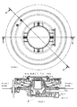
Figure 1 ; perspective view of the invention -
Figure 2 ; side view of the invention that is mounted to the cooker. -
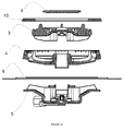
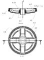
Figure 3 ; expanded cross-section view of the invention along A-A axis. -
Figure 4 ; expanded cross-section view of the invention along B-B axis. -
Figure 5 ; expanded cross-section view of the invention along C-C axis. -
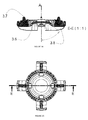
Figure 6 ; perspective view of the injector holder of the invention -
Figure 7 ; perspective view of the injector holder of the invention from the other side, -
Figure 8 ; to view of the injector holder of the invention, -
Figure 9 ; D-D cross-section view of the injector holder of the invention, -
Figure 10 ; blasted cross-section view of the invention -
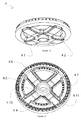
Figure 11 ; perspective view of the small crown of the invention -
Figure 12 ; perspective view of the small crown of the invention from the other side -
Figure 13 ; E-E cross-section view of the small crown of the invention -
Figure 14 ; top view of the small crown of the invention -
Figure 15 ; perspective view of the big crown of the invention -
Figure 16 ; perspective view of the big crown of the invention from the other side -
Figure 17 ; F-F cross-section view of the big crown of the invention -
- 1. Burner of the said invention
- 2. Injector
- 3. Small flame crown
- 3.1. Ports of small flame crown
- 3.2. Four grooves at the bottom of the small flame crown (3)
- 3.3. The bottom surface located at the center of the small flame crown (3) and creates horizontal venturi effect
- 3.4. Four bores minimum one distributed radially around the center of the small flame crown (3)
- 3.5. Top surface located in the center of the small flame crown (3)
- 3.6. Inclined surface located at the end of the bottom surface (3.3) located at the center of the small flame crown (3) and creates horizontal venturi effect
- 3.7. Four elevations distributed radially to the peripheral of the ports of small flame crown (3)
- 3.8. Side walls of four grooves (3.2)
- 3.9. Top walls of grooves (3.2)
- 4. Big flame crown
- 4.1. Grooves located at the bottom of the big flame crown (4)
- 4.2. Level of the grooves (4.1) located at the bottom of the big flame crown (4)
- 4.3. Bore creates vertical venturi effect
- 4.4. Air grooves those provide secondary air suction
- 4.5. Inner ports of the big flame crown (4)
- 4.6. Four grooves as minimum two distributed radially in the inner side of big flame crown (4)
- 4.7. Side walls of the groove (4.6)
- 4.8. Outer ports of the big flame crown (4)
- 4.9. Peripheral groove located in the big flame crown (4)
- 4.10. Surface at the end of the bore (4.3) that creates vertical venturi effect
- 4.11. Outer surface that covers the bore (4.3) that creates vertical venturi effect
- 5. injector holder
- 5.1. injector holder skirt
- 5.2. Four peripheral bores on injector holder skirts (5.1)
- 5.3. Thermo coupling slot
- 5.4. Ignition unit slot
- 5.5. Pin
- 5.6. Bore located at the bottom of the injector holder (5)
- 5.7. Grooves having certain profile
- 5.8. Walls rising around the grooves (5.7) of the injector holder (5)
- 6. Iron sheet located on the oven and cooker
- 7. Volume (7) that provides the suction of primary air
- 7.1. Inlet of the volume (7)
- 7.2. Outlet of the volume
- 8. Second volume that provides air/gas mixture
- 8.1. Outlet of the volume(8)
- 9. Small flame cover
- 10. Big flame cover
- 11. Thermo coupling
- 12. Ignition unit
- 13. Screws
- The invention is tried to be explained in details based upon the attached drawings. In order to mount said invention burner (1) to a cooker; there are the injector holder (5) that carries the injector (2), thermo coupling (11) and ignition unit (12), small flame crown (3) and big flame crown (4) to be mounted to oven iron sheet (6), four bores (5.2) on the periphery of injector holder skirts (5.1), two thermo coupling slots (5.3) for the purpose of providing the attachment of security system to the invention, an ignition unit slot (5.4) for the purpose of providing more rigid attachment of the invention three pins (5.5) and two bores (5.6) in points close to these pins (5.5) as shown in
Figure 2 . The said invention can be mounted into the oven easily by screws (13) by means of four bores (5.2) on the periphery of the injector holder skirts (5.1), three pins (5.5) located at the bottom of the injector holder (5) and two bores (5.6) at close points to these pins (5.5). Four bores (5.2) on the periphery of the injector holder skirts (5.1), three pins (5.5) located at the bottom of the injector holder (5) and two bores (5.6) at close points to these pins (5.5) are designed with the same distances of bore centers of the burners in the known state of art. Due to this oven producers may use this invention without making any modification in the designs of ovens and cookers those they use previously. However, in case of requested, these mounting points may be brought to requested measures.
Two thermo coupling slots (5.3) for the purpose of providing the attachment of security system to the above said invention do not exist in the known state of art. - The purpose for making these slots (5.3) as two units one of these slots is placed in a different position and in another implementation it is placed in another position in the previous known state of art This invention gets together two different implementation on a single injector holder (5). Due to this oven and cooker producers can use this invention without modifying security slot bores (6.1) bored on the iron sheet (6) placed on ovens or cookers.
- Grooves (5.7) having a specific tapered profile minimum two units distributed radially are used in perspective view of the injector holder of the burner (5) used in the invention on
Figure 8 . These grooves (5.7) may be used as four units preferably. The α angle of this said groove is between 20° and 80° relative to A axis and inclined around 60° preferably. The invention is designed such that when the above said big flame crown (4) is joined with the injector holder, a volume (7) is formed when the groove of the said injector holder (5.7) is joined with grooves (4.1) located at the bottom of big flame crown (4). Inlet orifice (7.1) of this volume provides primary air suction from external environment by staying at the top of iron sheet (6) of oven or cooker. The outlet orifice of this volume (7.2) is opened to mixing chamber of the injector holder (5). - There are walls (5.8) rising around the grooves (5.7) of the injector holder (5) at the surrounding of the groove of the injector holder of the burner. Turning of big flame crown (4) to right or left is prevented by clamping the level (4.2) of grooves (4.1)located at the bottom of the big flame crown (4) by means of elevating these walls (5.8) with a certain angle. An angle relative to B axis of the elevated walls (5.8) is between 5° and 45° and inclined an angle around 10° preferably. The injector holder (5) and the big flame crown is connected to each other in the way that is explained in above.
- There is bore (4.3) located in the middle center of big flame crown (4) and created venturi effect. There is a certain tapered angle in this bore (4.3). By way of mixing this flammable gas exiting from the orifice of injector (2) and air that comes from the exit orifice (7.2) of the volume (7) from which primary air comes are suctioned towards above from this bore (4.3). Four air grooves (4.4) minimum two which provide secondary air suction those look like slices so as triangle distributed radially around the bore (4.3) located at the middle center of big flame crown(4). These air grooves (4.4) in the invention provides air feeding of ports (3.1) of small flame crown (3) and inner ports (4.5) of big flame crown (4) by suctioning secondary air from external environment from just external side of iron sheet of oven and cooker (6).
- The purpose in here is to prevent the cutoff of the secondary air by saucepan or pan located multi-burning burner (1) during cooking on oven or cooker. If the secondary air is not suctioned into the system, the feeding the ports of small flame crown and inner ports of big flame crown will be cut and these ports will be turned off. The emission rates of burner will be increased by blowing unburned gas to environment.
- There are four grooves (4.6) as minimum two distributed radially in the inner side of big flame crown (4). Side walls (4.7) of this groove (4.6) is made in the form that it will be leveled. The side walls (3.8) of four air grooves (3.2) minimum two grooves which are distributed radially located at the bottom of small flame crown (3) are designed to be engaged inside of four air grooves (4.6) at least two grooves distributed radially inner side of big flame crown (4). Ω angle of top walls of (3.9) said grooves (3.2) are inclined between 2° and 25° preferably 5° to C axis. Small flame crown (3) and big flame crown (4) are attached to each other by this way. Turning of small flame crown (3) to right or left is prevented by locking it to the big flame crown (4) in this way. A second volume is formed by the engagement of side walls (4.7) of four grooves (3.2) minimum two distributed radially and located at the bottom of small flame crown (3) into side walls (4.7) of four grooves (3.2) minimum two distributed radially located inside of the big flame crown (4). The said volume (8) provides feeding of ports (3.1) of small flame crown (3), inner ports (4.5) and outer ports (4.8) of big flame crown(4) by the suction of primary air/gas mixture that comes out from the bore (4.3) located at middle center of big flame crown (4) and that creates vertical venturi effect by this volume (8). Before the primary air/gas mixture that comes our from the bore (4.3) that creates vertical venturi effect fill into the second volume (8) acts towards the said volume by striking to the bottom surface (3.3) located at the center of small flame crown (3) and creates horizontal venturi effect. A part of primary air/gas mixture reached to upper surface (3.5) of small flame crown (3) by coming out from four bores (3.4) minimum one distributed radially around the center of small flame crown (3). The primary air/gas mixture that comes our with a certain form from here is provided to come out from ports (3.1) of small flame (3) crown by striking to the cover of small flame (9). The exit of the other part of the primary air/gas mixture from the inner (4.5) and outer (4.8) ports of big flame crown (4) is provided by continuing its movement, coming out of outlet orifice (8.1) second volume (8), striking onto the big flame cover (9) located on big flame crown, distributing into peripheral groove located into big flame crown (4).
- Burning of the system is provided by ignition unit (12) placed to an ignition unit slot (5.4) located for providing the attachment of ignition unit to the invention. The burning together with ignition starts in outer port (4.8) and inner port (4.5) of big flame crown (4) of the burner (1). Inner ports (4.5) of big flame crown (4.5) is located such that burning is provided in outer ports (3.1) of small flame crown (3)immediately after the initial ignition. 10
- Another specification of the invention is that the area of outlet orifice (8.1) of second volume (8) is between 1 % and 15 % preferably around 3 % of total area of peripheral groove (4.9) located in big flame crown.
- Another specification of the invention is that at least the area of one of the bores from four bores (3.4) distributed radially around the center of small flame crown (3) is between 1 % and 10 % preferably around 2 % of the total area of the upper surface (3.5) located at the center of small flame crown (3).
- Another specification of the invention is that the angle γ of the angled surface (3.6) located at the end of the bottom surface located at the center of small flame crown and creates horizontal venturi effect is inclined between 20° and 70° preferably around 50° relative to A axis.
- Another specification of the invention is that the distance between surface(4.3) at the end of the bore (4.3) that created vertical venturi effect in big flame crown (4) after small flame crown (3) is mounted to big flame crown (4) and bottom surface (3.3) located at small flame crown (3) and creates horizontal venturi effect is between 1 and 10 mm preferably around 2.5 mm.
- Another specification of the invention is the burning may be increased or decreased in small flame crown (3) by changing diameter of the ports of small flame crown (3). This change may only be possible by changing small flame crown (3).
- Another specification of the invention is that ϕ angle of external surface (4.11) that covers the bore (4.3) which creates vertical venturi effect at big flame crown (4) is inclined between 5° and 45°, preferably 10° relative to A axis.
- Another specification of the invention is that there are at least four elevations (3.7) distributed radially to outer periphery of the ports of small flame crown (3). The external diameter distances of these elevations (3.7) to each other is smaller than the internal diameter of big flame cover (10) Sliding of the big flame cover (10) to the ports of the small flame crown (3.1) is prevented by this way. Also another purpose of this elevation (3.7) is to prevent turn off of these ports (3.1) by closing small flame crown ports (3.1) directly with their bottoms, in case of saucepan, pan or pot with small diameter are put on the burner.
- Another specification of the invention is that the injector holder (5), big flame crown (4) and small flame crown (3) mentioned in above and constitute the main burst of burner (1) are produced by casting method and they can be mounted to each other without machining.
- By means of this since the burner (1) is produced more easily than other burners used currently, by decreasing the cost in great ratio it provides ease of implementation of this type burners to ovens and cookers.
- The invention is convenient to be used in all places where these type multi burners are used currently. Particularly it is convenient to be used in household cookers.
- The protection content of this application is determined in claims section and cannot be limited by the explanations with the purpose illustration absolutely. It is obvious that an expert in technology may apply the novelty that is put forward in the invention by changing he forms of parts and using similar structures to other areas. Therefore, it is obvious that such structures are deprived of the criteria of novelty.
Claims (19)
Applications Claiming Priority (1)
| Application Number | Priority Date | Filing Date | Title |
|---|---|---|---|
| TR2009/01741A TR200901741A2 (en) | 2009-03-06 | 2009-03-06 | Multiple gas burner for furnaces. |
Publications (2)
| Publication Number | Publication Date |
|---|---|
| EP2226560A2 true EP2226560A2 (en) | 2010-09-08 |
| EP2226560A3 EP2226560A3 (en) | 2015-09-02 |
Family
ID=42230235
Family Applications (1)
| Application Number | Title | Priority Date | Filing Date |
|---|---|---|---|
| EP09179437.0A Withdrawn EP2226560A3 (en) | 2009-03-06 | 2009-12-16 | Burner with multiple flame rings for ranges |
Country Status (2)
| Country | Link |
|---|---|
| EP (1) | EP2226560A3 (en) |
| TR (1) | TR200901741A2 (en) |
Cited By (13)
| Publication number | Priority date | Publication date | Assignee | Title |
|---|---|---|---|---|
| CN102466228A (en) * | 2010-10-28 | 2012-05-23 | 林内株式会社 | Gas burner |
| WO2012085610A1 (en) * | 2010-12-22 | 2012-06-28 | Sabaf S.P.A. | Gas burner |
| CN102563647A (en) * | 2010-12-09 | 2012-07-11 | 樱花卫厨(中国)股份有限公司 | Combustor integrated with full-premixed combustion and atmospheric combustion |
| CN103418773A (en) * | 2012-05-17 | 2013-12-04 | 萨巴夫股份有限公司 | Method for manufacturing a gas burner |
| CN103900087A (en) * | 2014-02-10 | 2014-07-02 | 广东美的厨房电器制造有限公司 | Burner and gas stove |
| EP2884176A3 (en) * | 2013-12-11 | 2015-08-12 | Whirlpool Corporation | Additional primary air supply for cooktop gas burners |
| EP2629010A3 (en) * | 2012-02-16 | 2018-01-10 | Jinhong Liang | Burner for gas ovens |
| US10317088B2 (en) | 2015-07-02 | 2019-06-11 | Mabe, S.A. De C.V. | Triple ring flame burner |
| WO2019223402A1 (en) * | 2018-05-23 | 2019-11-28 | 宁波方太厨具有限公司 | Upper air inlet cooker burner |
| CN112128759A (en) * | 2020-09-30 | 2020-12-25 | 宁波方太厨具有限公司 | Stove burner |
| CN112856412A (en) * | 2021-01-12 | 2021-05-28 | 宁波方太厨具有限公司 | Combustor base, combustor and cooking utensils |
| US11234557B2 (en) | 2018-03-14 | 2022-02-01 | Ashley Bryant | Stovetop cooking and grilling assembly |
| WO2022240373A3 (en) * | 2021-05-12 | 2023-03-23 | Liva Gaz Armaturleri Ve Endustriyel Mutfak Aksesuarlari Sanayi Ve Ticaret Limited Sirketi | Burner for gas stoves |
Families Citing this family (1)
| Publication number | Priority date | Publication date | Assignee | Title |
|---|---|---|---|---|
| EP2868968A1 (en) | 2013-11-04 | 2015-05-06 | Turas Gaz Armatürleri Sanayi. Ve Ticaret A.S. | Burner Having Multiple Burning Rings |
Family Cites Families (3)
| Publication number | Priority date | Publication date | Assignee | Title |
|---|---|---|---|---|
| FR2804496B1 (en) * | 2000-01-28 | 2002-07-19 | Sourdillon Sa | MULTIPLE FLAME CROWN GAS BURNER |
| EP1714075B1 (en) * | 2004-01-23 | 2012-07-11 | Burner Systems International (BSI) | Gas burner for a cooking applicance |
| ITMC20050036A1 (en) * | 2005-04-29 | 2006-10-30 | So M I Press Societa Metalli Iniettati Spa | DOUBLE BURNER FOR GAS COOKERS, WITH MULTIPLE CONCENTRIC FLAME CHAINS, HIGH POWER. |
-
2009
- 2009-03-06 TR TR2009/01741A patent/TR200901741A2/en unknown
- 2009-12-16 EP EP09179437.0A patent/EP2226560A3/en not_active Withdrawn
Non-Patent Citations (1)
| Title |
|---|
| None * |
Cited By (24)
| Publication number | Priority date | Publication date | Assignee | Title |
|---|---|---|---|---|
| CN102466228A (en) * | 2010-10-28 | 2012-05-23 | 林内株式会社 | Gas burner |
| CN102466228B (en) * | 2010-10-28 | 2015-06-10 | 林内株式会社 | Gas burner |
| CN102563647A (en) * | 2010-12-09 | 2012-07-11 | 樱花卫厨(中国)股份有限公司 | Combustor integrated with full-premixed combustion and atmospheric combustion |
| WO2012085610A1 (en) * | 2010-12-22 | 2012-06-28 | Sabaf S.P.A. | Gas burner |
| CN102563644A (en) * | 2010-12-22 | 2012-07-11 | 萨巴夫股份有限公司 | Gas burner |
| US10247410B2 (en) | 2010-12-22 | 2019-04-02 | Sabaf S.P.A. | Gas burner |
| AU2010366054B2 (en) * | 2010-12-22 | 2015-06-11 | Sabaf S.P.A. | Gas burner |
| CN102563644B (en) * | 2010-12-22 | 2015-08-19 | 萨巴夫股份有限公司 | gas burner |
| EP2629010A3 (en) * | 2012-02-16 | 2018-01-10 | Jinhong Liang | Burner for gas ovens |
| CN103418773A (en) * | 2012-05-17 | 2013-12-04 | 萨巴夫股份有限公司 | Method for manufacturing a gas burner |
| CN103418773B (en) * | 2012-05-17 | 2016-06-29 | 萨巴夫股份有限公司 | For the method manufacturing gas burner |
| US9513012B2 (en) | 2013-12-11 | 2016-12-06 | Whirlpool Corporation | Additional primary air access for surface gas burners |
| EP2884176A3 (en) * | 2013-12-11 | 2015-08-12 | Whirlpool Corporation | Additional primary air supply for cooktop gas burners |
| US10228128B2 (en) | 2013-12-11 | 2019-03-12 | Whirlpool Corporation | Additional primary air access for surface gas burners |
| US11098891B2 (en) | 2013-12-11 | 2021-08-24 | Whirlpool Corporation | Additional primary air access for surface gas burners |
| CN103900087B (en) * | 2014-02-10 | 2016-08-17 | 广东美的厨房电器制造有限公司 | Burner and gas-cooker |
| CN103900087A (en) * | 2014-02-10 | 2014-07-02 | 广东美的厨房电器制造有限公司 | Burner and gas stove |
| US10317088B2 (en) | 2015-07-02 | 2019-06-11 | Mabe, S.A. De C.V. | Triple ring flame burner |
| US11234557B2 (en) | 2018-03-14 | 2022-02-01 | Ashley Bryant | Stovetop cooking and grilling assembly |
| WO2019223402A1 (en) * | 2018-05-23 | 2019-11-28 | 宁波方太厨具有限公司 | Upper air inlet cooker burner |
| CN112128759A (en) * | 2020-09-30 | 2020-12-25 | 宁波方太厨具有限公司 | Stove burner |
| CN112128759B (en) * | 2020-09-30 | 2021-07-23 | 宁波方太厨具有限公司 | Stove burner |
| CN112856412A (en) * | 2021-01-12 | 2021-05-28 | 宁波方太厨具有限公司 | Combustor base, combustor and cooking utensils |
| WO2022240373A3 (en) * | 2021-05-12 | 2023-03-23 | Liva Gaz Armaturleri Ve Endustriyel Mutfak Aksesuarlari Sanayi Ve Ticaret Limited Sirketi | Burner for gas stoves |
Also Published As
| Publication number | Publication date |
|---|---|
| EP2226560A3 (en) | 2015-09-02 |
| TR200901741A2 (en) | 2009-08-21 |
Similar Documents
| Publication | Publication Date | Title |
|---|---|---|
| EP2226560A2 (en) | Burner with multiple flame rings for ranges | |
| EP2140200B1 (en) | Improved gas burner for cooking appliances | |
| EP1838997B1 (en) | Gas burner for cooking appliances | |
| RU2650455C2 (en) | Improved gas burner | |
| US10145568B2 (en) | High efficiency high power inner flame burner | |
| JP2006505761A (en) | Gas burner for cooker | |
| KR20170127019A (en) | Bottom cup covers and burners and gas appliances | |
| US11530819B2 (en) | Pan support, a gas stove and a method for producing a pan support | |
| CN108443883B (en) | Fire cover, burner and gas cooker | |
| CN111853789B (en) | Flat-plate combustor and flat-plate gas stove | |
| CN211060111U (en) | Structure is adjusted to gas air inlet that mixes | |
| CN111964054B (en) | Inner ring fire cover for combustor and combustor with inner ring fire cover | |
| CN109416174B (en) | Gas burner and household cooking appliance | |
| CN114051572A (en) | Gas burner | |
| CN114278938A (en) | Burner fire cover and burner | |
| CN110657430A (en) | Burner for kitchen range | |
| CN210267207U (en) | Stove burner assembly | |
| CN111256125B (en) | Burner for gas stove | |
| CN209840089U (en) | Burner of gas stove | |
| CN215863392U (en) | Burner for gas stove | |
| CN216844675U (en) | Burner fire cover and burner | |
| CN216079796U (en) | Burner for gas stove | |
| CN215216238U (en) | Burner fire cover and burner using same | |
| CN217274118U (en) | Burner for gas stove | |
| CN219713347U (en) | Complete upper air inlet kitchen range |
Legal Events
| Date | Code | Title | Description |
|---|---|---|---|
| PUAI | Public reference made under article 153(3) epc to a published international application that has entered the european phase |
Free format text: ORIGINAL CODE: 0009012 |
|
| AK | Designated contracting states |
Kind code of ref document: A2 Designated state(s): AT BE BG CH CY CZ DE DK EE ES FI FR GB GR HR HU IE IS IT LI LT LU LV MC MK MT NL NO PL PT RO SE SI SK SM TR |
|
| PUAL | Search report despatched |
Free format text: ORIGINAL CODE: 0009013 |
|
| AK | Designated contracting states |
Kind code of ref document: A3 Designated state(s): AT BE BG CH CY CZ DE DK EE ES FI FR GB GR HR HU IE IS IT LI LT LU LV MC MK MT NL NO PL PT RO SE SI SK SM TR |
|
| AX | Request for extension of the european patent |
Extension state: AL BA RS |
|
| RIC1 | Information provided on ipc code assigned before grant |
Ipc: F23D 14/64 20060101ALI20150724BHEP Ipc: F23D 14/06 20060101AFI20150724BHEP |
|
| 17P | Request for examination filed |
Effective date: 20150915 |
|
| 17Q | First examination report despatched |
Effective date: 20180424 |
|
| STAA | Information on the status of an ep patent application or granted ep patent |
Free format text: STATUS: THE APPLICATION IS DEEMED TO BE WITHDRAWN |
|
| 18D | Application deemed to be withdrawn |
Effective date: 20180905 |