EP3971325A1 - Système de génération de h2 et de capture de co2 - Google Patents
Système de génération de h2 et de capture de co2 Download PDFInfo
- Publication number
- EP3971325A1 EP3971325A1 EP20306071.0A EP20306071A EP3971325A1 EP 3971325 A1 EP3971325 A1 EP 3971325A1 EP 20306071 A EP20306071 A EP 20306071A EP 3971325 A1 EP3971325 A1 EP 3971325A1
- Authority
- EP
- European Patent Office
- Prior art keywords
- supercapacitive
- particles
- zone
- compartment
- electrode compartment
- Prior art date
- Legal status (The legal status is an assumption and is not a legal conclusion. Google has not performed a legal analysis and makes no representation as to the accuracy of the status listed.)
- Withdrawn
Links
- 229910001868 water Inorganic materials 0.000 claims abstract description 45
- 238000005868 electrolysis reaction Methods 0.000 claims abstract description 44
- 238000000034 method Methods 0.000 claims abstract description 43
- XLYOFNOQVPJJNP-UHFFFAOYSA-N water Substances O XLYOFNOQVPJJNP-UHFFFAOYSA-N 0.000 claims abstract description 43
- 230000008569 process Effects 0.000 claims abstract description 41
- UFHFLCQGNIYNRP-UHFFFAOYSA-N Hydrogen Chemical compound [H][H] UFHFLCQGNIYNRP-UHFFFAOYSA-N 0.000 claims abstract description 37
- 238000004519 manufacturing process Methods 0.000 claims abstract description 21
- 238000004891 communication Methods 0.000 claims abstract description 10
- 230000009467 reduction Effects 0.000 claims abstract description 7
- 239000002245 particle Substances 0.000 claims description 92
- OKTJSMMVPCPJKN-UHFFFAOYSA-N Carbon Chemical compound [C] OKTJSMMVPCPJKN-UHFFFAOYSA-N 0.000 claims description 55
- 239000003792 electrolyte Substances 0.000 claims description 48
- CURLTUGMZLYLDI-UHFFFAOYSA-N Carbon dioxide Chemical compound O=C=O CURLTUGMZLYLDI-UHFFFAOYSA-N 0.000 claims description 47
- 229910052799 carbon Inorganic materials 0.000 claims description 43
- 229910002092 carbon dioxide Inorganic materials 0.000 claims description 39
- 239000001569 carbon dioxide Substances 0.000 claims description 39
- 238000003860 storage Methods 0.000 claims description 34
- -1 hydroxide ions Chemical class 0.000 claims description 24
- BVKZGUZCCUSVTD-UHFFFAOYSA-N carbonic acid Chemical compound OC(O)=O BVKZGUZCCUSVTD-UHFFFAOYSA-N 0.000 claims description 16
- 150000003839 salts Chemical class 0.000 claims description 16
- BVKZGUZCCUSVTD-UHFFFAOYSA-M Bicarbonate Chemical compound OC([O-])=O BVKZGUZCCUSVTD-UHFFFAOYSA-M 0.000 claims description 11
- BVKZGUZCCUSVTD-UHFFFAOYSA-L Carbonate Chemical compound [O-]C([O-])=O BVKZGUZCCUSVTD-UHFFFAOYSA-L 0.000 claims description 9
- 239000012528 membrane Substances 0.000 claims description 9
- 239000007787 solid Substances 0.000 claims description 8
- 229910002091 carbon monoxide Inorganic materials 0.000 claims description 7
- UGFAIRIUMAVXCW-UHFFFAOYSA-N Carbon monoxide Chemical compound [O+]#[C-] UGFAIRIUMAVXCW-UHFFFAOYSA-N 0.000 claims description 6
- 238000000354 decomposition reaction Methods 0.000 claims description 5
- 238000007599 discharging Methods 0.000 claims description 4
- MYMOFIZGZYHOMD-UHFFFAOYSA-N Dioxygen Chemical compound O=O MYMOFIZGZYHOMD-UHFFFAOYSA-N 0.000 claims description 3
- 229910001882 dioxygen Inorganic materials 0.000 claims description 3
- 239000004215 Carbon black (E152) Substances 0.000 claims description 2
- 150000001875 compounds Chemical class 0.000 claims description 2
- 229930195733 hydrocarbon Natural products 0.000 claims description 2
- 150000002430 hydrocarbons Chemical class 0.000 claims description 2
- 239000000725 suspension Substances 0.000 claims description 2
- 239000002609 medium Substances 0.000 description 23
- 239000001257 hydrogen Substances 0.000 description 17
- 229910052739 hydrogen Inorganic materials 0.000 description 17
- VTYYLEPIZMXCLO-UHFFFAOYSA-L calcium carbonate Substances [Ca+2].[O-]C([O-])=O VTYYLEPIZMXCLO-UHFFFAOYSA-L 0.000 description 14
- 238000006243 chemical reaction Methods 0.000 description 13
- 239000000758 substrate Substances 0.000 description 9
- 229910052784 alkaline earth metal Inorganic materials 0.000 description 8
- 239000011575 calcium Substances 0.000 description 8
- 239000002002 slurry Substances 0.000 description 8
- PXHVJJICTQNCMI-UHFFFAOYSA-N nickel Substances [Ni] PXHVJJICTQNCMI-UHFFFAOYSA-N 0.000 description 7
- UXVMQQNJUSDDNG-UHFFFAOYSA-L Calcium chloride Chemical compound [Cl-].[Cl-].[Ca+2] UXVMQQNJUSDDNG-UHFFFAOYSA-L 0.000 description 6
- 239000012736 aqueous medium Substances 0.000 description 6
- 229910000019 calcium carbonate Inorganic materials 0.000 description 6
- XLYOFNOQVPJJNP-ZSJDYOACSA-N heavy water Substances [2H]O[2H] XLYOFNOQVPJJNP-ZSJDYOACSA-N 0.000 description 6
- 239000007788 liquid Substances 0.000 description 6
- 229910002640 NiOOH Inorganic materials 0.000 description 5
- 239000001110 calcium chloride Substances 0.000 description 5
- 229910001628 calcium chloride Inorganic materials 0.000 description 5
- 239000007789 gas Substances 0.000 description 5
- 239000000243 solution Substances 0.000 description 5
- 229910000990 Ni alloy Inorganic materials 0.000 description 4
- 239000003513 alkali Substances 0.000 description 4
- QVGXLLKOCUKJST-UHFFFAOYSA-N atomic oxygen Chemical compound [O] QVGXLLKOCUKJST-UHFFFAOYSA-N 0.000 description 4
- 230000015572 biosynthetic process Effects 0.000 description 4
- 150000004649 carbonic acid derivatives Chemical class 0.000 description 4
- 239000003054 catalyst Substances 0.000 description 4
- 230000000694 effects Effects 0.000 description 4
- 239000011244 liquid electrolyte Substances 0.000 description 4
- 229910021508 nickel(II) hydroxide Inorganic materials 0.000 description 4
- 230000003647 oxidation Effects 0.000 description 4
- 238000007254 oxidation reaction Methods 0.000 description 4
- 239000001301 oxygen Substances 0.000 description 4
- 229910052760 oxygen Inorganic materials 0.000 description 4
- HEMHJVSKTPXQMS-UHFFFAOYSA-M Sodium hydroxide Chemical compound [OH-].[Na+] HEMHJVSKTPXQMS-UHFFFAOYSA-M 0.000 description 3
- 150000001342 alkaline earth metals Chemical class 0.000 description 3
- 230000008901 benefit Effects 0.000 description 3
- 229910052791 calcium Inorganic materials 0.000 description 3
- 230000003197 catalytic effect Effects 0.000 description 3
- 238000002484 cyclic voltammetry Methods 0.000 description 3
- 239000012530 fluid Substances 0.000 description 3
- 229910052749 magnesium Inorganic materials 0.000 description 3
- VNWKTOKETHGBQD-UHFFFAOYSA-N methane Chemical compound C VNWKTOKETHGBQD-UHFFFAOYSA-N 0.000 description 3
- 239000000203 mixture Substances 0.000 description 3
- 230000010287 polarization Effects 0.000 description 3
- 239000010935 stainless steel Substances 0.000 description 3
- 229910001220 stainless steel Inorganic materials 0.000 description 3
- 238000011144 upstream manufacturing Methods 0.000 description 3
- IJGRMHOSHXDMSA-UHFFFAOYSA-N Atomic nitrogen Chemical compound N#N IJGRMHOSHXDMSA-UHFFFAOYSA-N 0.000 description 2
- 150000001450 anions Chemical class 0.000 description 2
- 238000013459 approach Methods 0.000 description 2
- 229940075397 calomel Drugs 0.000 description 2
- 229910021401 carbide-derived carbon Inorganic materials 0.000 description 2
- 239000002041 carbon nanotube Substances 0.000 description 2
- 229910021393 carbon nanotube Inorganic materials 0.000 description 2
- 230000008878 coupling Effects 0.000 description 2
- 238000010168 coupling process Methods 0.000 description 2
- 238000005859 coupling reaction Methods 0.000 description 2
- ZOMNIUBKTOKEHS-UHFFFAOYSA-L dimercury dichloride Chemical compound Cl[Hg][Hg]Cl ZOMNIUBKTOKEHS-UHFFFAOYSA-L 0.000 description 2
- 239000008151 electrolyte solution Substances 0.000 description 2
- 230000007613 environmental effect Effects 0.000 description 2
- SZVJSHCCFOBDDC-UHFFFAOYSA-N ferrosoferric oxide Chemical compound O=[Fe]O[Fe]O[Fe]=O SZVJSHCCFOBDDC-UHFFFAOYSA-N 0.000 description 2
- 238000002347 injection Methods 0.000 description 2
- 239000007924 injection Substances 0.000 description 2
- NUJOXMJBOLGQSY-UHFFFAOYSA-N manganese dioxide Chemical compound O=[Mn]=O NUJOXMJBOLGQSY-UHFFFAOYSA-N 0.000 description 2
- 239000000463 material Substances 0.000 description 2
- 229910052751 metal Inorganic materials 0.000 description 2
- 239000002184 metal Substances 0.000 description 2
- 229910044991 metal oxide Inorganic materials 0.000 description 2
- 229910052759 nickel Inorganic materials 0.000 description 2
- 238000004313 potentiometry Methods 0.000 description 2
- 239000002244 precipitate Substances 0.000 description 2
- 230000001737 promoting effect Effects 0.000 description 2
- 238000004064 recycling Methods 0.000 description 2
- 230000004044 response Effects 0.000 description 2
- 230000002269 spontaneous effect Effects 0.000 description 2
- 230000003068 static effect Effects 0.000 description 2
- 238000012546 transfer Methods 0.000 description 2
- 239000004966 Carbon aerogel Substances 0.000 description 1
- OKTJSMMVPCPJKN-IGMARMGPSA-N Carbon-12 Chemical compound [12C] OKTJSMMVPCPJKN-IGMARMGPSA-N 0.000 description 1
- VEXZGXHMUGYJMC-UHFFFAOYSA-M Chloride anion Chemical compound [Cl-] VEXZGXHMUGYJMC-UHFFFAOYSA-M 0.000 description 1
- 238000009825 accumulation Methods 0.000 description 1
- 230000002378 acidificating effect Effects 0.000 description 1
- 238000004458 analytical method Methods 0.000 description 1
- 125000000129 anionic group Chemical group 0.000 description 1
- 239000007864 aqueous solution Substances 0.000 description 1
- 230000033558 biomineral tissue development Effects 0.000 description 1
- 239000003738 black carbon Substances 0.000 description 1
- 235000010216 calcium carbonate Nutrition 0.000 description 1
- 238000004364 calculation method Methods 0.000 description 1
- 239000003990 capacitor Substances 0.000 description 1
- 235000019241 carbon black Nutrition 0.000 description 1
- 239000003575 carbonaceous material Substances 0.000 description 1
- 238000010349 cathodic reaction Methods 0.000 description 1
- 230000008859 change Effects 0.000 description 1
- 239000002131 composite material Substances 0.000 description 1
- 239000012141 concentrate Substances 0.000 description 1
- 229920001940 conductive polymer Polymers 0.000 description 1
- 238000010276 construction Methods 0.000 description 1
- 238000010612 desalination reaction Methods 0.000 description 1
- 238000013461 design Methods 0.000 description 1
- 238000002296 dynamic light scattering Methods 0.000 description 1
- 230000005611 electricity Effects 0.000 description 1
- 230000001747 exhibiting effect Effects 0.000 description 1
- 239000004744 fabric Substances 0.000 description 1
- 239000006260 foam Substances 0.000 description 1
- 229910021389 graphene Inorganic materials 0.000 description 1
- 239000010439 graphite Substances 0.000 description 1
- 229910002804 graphite Inorganic materials 0.000 description 1
- 125000005842 heteroatom Chemical group 0.000 description 1
- 150000002431 hydrogen Chemical class 0.000 description 1
- 150000004706 metal oxides Chemical class 0.000 description 1
- 238000001465 metallisation Methods 0.000 description 1
- 238000002156 mixing Methods 0.000 description 1
- BFDHFSHZJLFAMC-UHFFFAOYSA-L nickel(ii) hydroxide Chemical compound [OH-].[OH-].[Ni+2] BFDHFSHZJLFAMC-UHFFFAOYSA-L 0.000 description 1
- 229910052757 nitrogen Inorganic materials 0.000 description 1
- 229910000510 noble metal Inorganic materials 0.000 description 1
- 238000003921 particle size analysis Methods 0.000 description 1
- 230000000737 periodic effect Effects 0.000 description 1
- 229920000642 polymer Polymers 0.000 description 1
- 230000008092 positive effect Effects 0.000 description 1
- 238000001556 precipitation Methods 0.000 description 1
- 238000002407 reforming Methods 0.000 description 1
- 230000008929 regeneration Effects 0.000 description 1
- 238000011069 regeneration method Methods 0.000 description 1
- 230000001105 regulatory effect Effects 0.000 description 1
- 239000013535 sea water Substances 0.000 description 1
- HPALAKNZSZLMCH-UHFFFAOYSA-M sodium;chloride;hydrate Chemical group O.[Na+].[Cl-] HPALAKNZSZLMCH-UHFFFAOYSA-M 0.000 description 1
- 238000001179 sorption measurement Methods 0.000 description 1
- 239000000126 substance Substances 0.000 description 1
- 238000004832 voltammetry Methods 0.000 description 1
Images


Classifications
-
- C—CHEMISTRY; METALLURGY
- C25—ELECTROLYTIC OR ELECTROPHORETIC PROCESSES; APPARATUS THEREFOR
- C25B—ELECTROLYTIC OR ELECTROPHORETIC PROCESSES FOR THE PRODUCTION OF COMPOUNDS OR NON-METALS; APPARATUS THEREFOR
- C25B1/00—Electrolytic production of inorganic compounds or non-metals
- C25B1/01—Products
- C25B1/02—Hydrogen or oxygen
- C25B1/04—Hydrogen or oxygen by electrolysis of water
-
- C—CHEMISTRY; METALLURGY
- C25—ELECTROLYTIC OR ELECTROPHORETIC PROCESSES; APPARATUS THEREFOR
- C25B—ELECTROLYTIC OR ELECTROPHORETIC PROCESSES FOR THE PRODUCTION OF COMPOUNDS OR NON-METALS; APPARATUS THEREFOR
- C25B11/00—Electrodes; Manufacture thereof not otherwise provided for
- C25B11/04—Electrodes; Manufacture thereof not otherwise provided for characterised by the material
- C25B11/042—Electrodes formed of a single material
- C25B11/043—Carbon, e.g. diamond or graphene
-
- B—PERFORMING OPERATIONS; TRANSPORTING
- B01—PHYSICAL OR CHEMICAL PROCESSES OR APPARATUS IN GENERAL
- B01D—SEPARATION
- B01D53/00—Separation of gases or vapours; Recovering vapours of volatile solvents from gases; Chemical or biological purification of waste gases, e.g. engine exhaust gases, smoke, fumes, flue gases, aerosols
- B01D53/34—Chemical or biological purification of waste gases
- B01D53/46—Removing components of defined structure
- B01D53/62—Carbon oxides
-
- C—CHEMISTRY; METALLURGY
- C25—ELECTROLYTIC OR ELECTROPHORETIC PROCESSES; APPARATUS THEREFOR
- C25B—ELECTROLYTIC OR ELECTROPHORETIC PROCESSES FOR THE PRODUCTION OF COMPOUNDS OR NON-METALS; APPARATUS THEREFOR
- C25B1/00—Electrolytic production of inorganic compounds or non-metals
- C25B1/01—Products
- C25B1/14—Alkali metal compounds
- C25B1/16—Hydroxides
-
- C—CHEMISTRY; METALLURGY
- C25—ELECTROLYTIC OR ELECTROPHORETIC PROCESSES; APPARATUS THEREFOR
- C25B—ELECTROLYTIC OR ELECTROPHORETIC PROCESSES FOR THE PRODUCTION OF COMPOUNDS OR NON-METALS; APPARATUS THEREFOR
- C25B1/00—Electrolytic production of inorganic compounds or non-metals
- C25B1/01—Products
- C25B1/18—Alkaline earth metal compounds or magnesium compounds
- C25B1/20—Hydroxides
-
- C—CHEMISTRY; METALLURGY
- C25—ELECTROLYTIC OR ELECTROPHORETIC PROCESSES; APPARATUS THEREFOR
- C25B—ELECTROLYTIC OR ELECTROPHORETIC PROCESSES FOR THE PRODUCTION OF COMPOUNDS OR NON-METALS; APPARATUS THEREFOR
- C25B11/00—Electrodes; Manufacture thereof not otherwise provided for
- C25B11/02—Electrodes; Manufacture thereof not otherwise provided for characterised by shape or form
- C25B11/037—Electrodes made of particles
-
- C—CHEMISTRY; METALLURGY
- C25—ELECTROLYTIC OR ELECTROPHORETIC PROCESSES; APPARATUS THEREFOR
- C25B—ELECTROLYTIC OR ELECTROPHORETIC PROCESSES FOR THE PRODUCTION OF COMPOUNDS OR NON-METALS; APPARATUS THEREFOR
- C25B15/00—Operating or servicing cells
- C25B15/08—Supplying or removing reactants or electrolytes; Regeneration of electrolytes
- C25B15/081—Supplying products to non-electrochemical reactors that are combined with the electrochemical cell, e.g. Sabatier reactor
-
- C—CHEMISTRY; METALLURGY
- C25—ELECTROLYTIC OR ELECTROPHORETIC PROCESSES; APPARATUS THEREFOR
- C25B—ELECTROLYTIC OR ELECTROPHORETIC PROCESSES FOR THE PRODUCTION OF COMPOUNDS OR NON-METALS; APPARATUS THEREFOR
- C25B15/00—Operating or servicing cells
- C25B15/08—Supplying or removing reactants or electrolytes; Regeneration of electrolytes
- C25B15/087—Recycling of electrolyte to electrochemical cell
-
- C—CHEMISTRY; METALLURGY
- C25—ELECTROLYTIC OR ELECTROPHORETIC PROCESSES; APPARATUS THEREFOR
- C25B—ELECTROLYTIC OR ELECTROPHORETIC PROCESSES FOR THE PRODUCTION OF COMPOUNDS OR NON-METALS; APPARATUS THEREFOR
- C25B9/00—Cells or assemblies of cells; Constructional parts of cells; Assemblies of constructional parts, e.g. electrode-diaphragm assemblies; Process-related cell features
- C25B9/17—Cells comprising dimensionally-stable non-movable electrodes; Assemblies of constructional parts thereof
- C25B9/19—Cells comprising dimensionally-stable non-movable electrodes; Assemblies of constructional parts thereof with diaphragms
-
- B—PERFORMING OPERATIONS; TRANSPORTING
- B01—PHYSICAL OR CHEMICAL PROCESSES OR APPARATUS IN GENERAL
- B01D—SEPARATION
- B01D2251/00—Reactants
- B01D2251/60—Inorganic bases or salts
- B01D2251/604—Hydroxides
-
- B—PERFORMING OPERATIONS; TRANSPORTING
- B01—PHYSICAL OR CHEMICAL PROCESSES OR APPARATUS IN GENERAL
- B01D—SEPARATION
- B01D2257/00—Components to be removed
- B01D2257/50—Carbon oxides
- B01D2257/504—Carbon dioxide
-
- Y—GENERAL TAGGING OF NEW TECHNOLOGICAL DEVELOPMENTS; GENERAL TAGGING OF CROSS-SECTIONAL TECHNOLOGIES SPANNING OVER SEVERAL SECTIONS OF THE IPC; TECHNICAL SUBJECTS COVERED BY FORMER USPC CROSS-REFERENCE ART COLLECTIONS [XRACs] AND DIGESTS
- Y02—TECHNOLOGIES OR APPLICATIONS FOR MITIGATION OR ADAPTATION AGAINST CLIMATE CHANGE
- Y02C—CAPTURE, STORAGE, SEQUESTRATION OR DISPOSAL OF GREENHOUSE GASES [GHG]
- Y02C20/00—Capture or disposal of greenhouse gases
- Y02C20/40—Capture or disposal of greenhouse gases of CO2
-
- Y—GENERAL TAGGING OF NEW TECHNOLOGICAL DEVELOPMENTS; GENERAL TAGGING OF CROSS-SECTIONAL TECHNOLOGIES SPANNING OVER SEVERAL SECTIONS OF THE IPC; TECHNICAL SUBJECTS COVERED BY FORMER USPC CROSS-REFERENCE ART COLLECTIONS [XRACs] AND DIGESTS
- Y02—TECHNOLOGIES OR APPLICATIONS FOR MITIGATION OR ADAPTATION AGAINST CLIMATE CHANGE
- Y02E—REDUCTION OF GREENHOUSE GAS [GHG] EMISSIONS, RELATED TO ENERGY GENERATION, TRANSMISSION OR DISTRIBUTION
- Y02E60/00—Enabling technologies; Technologies with a potential or indirect contribution to GHG emissions mitigation
- Y02E60/30—Hydrogen technology
- Y02E60/36—Hydrogen production from non-carbon containing sources, e.g. by water electrolysis
-
- Y—GENERAL TAGGING OF NEW TECHNOLOGICAL DEVELOPMENTS; GENERAL TAGGING OF CROSS-SECTIONAL TECHNOLOGIES SPANNING OVER SEVERAL SECTIONS OF THE IPC; TECHNICAL SUBJECTS COVERED BY FORMER USPC CROSS-REFERENCE ART COLLECTIONS [XRACs] AND DIGESTS
- Y02—TECHNOLOGIES OR APPLICATIONS FOR MITIGATION OR ADAPTATION AGAINST CLIMATE CHANGE
- Y02P—CLIMATE CHANGE MITIGATION TECHNOLOGIES IN THE PRODUCTION OR PROCESSING OF GOODS
- Y02P20/00—Technologies relating to chemical industry
- Y02P20/10—Process efficiency
- Y02P20/133—Renewable energy sources, e.g. sunlight
-
- Y—GENERAL TAGGING OF NEW TECHNOLOGICAL DEVELOPMENTS; GENERAL TAGGING OF CROSS-SECTIONAL TECHNOLOGIES SPANNING OVER SEVERAL SECTIONS OF THE IPC; TECHNICAL SUBJECTS COVERED BY FORMER USPC CROSS-REFERENCE ART COLLECTIONS [XRACs] AND DIGESTS
- Y02—TECHNOLOGIES OR APPLICATIONS FOR MITIGATION OR ADAPTATION AGAINST CLIMATE CHANGE
- Y02P—CLIMATE CHANGE MITIGATION TECHNOLOGIES IN THE PRODUCTION OR PROCESSING OF GOODS
- Y02P20/00—Technologies relating to chemical industry
- Y02P20/151—Reduction of greenhouse gas [GHG] emissions, e.g. CO2
Definitions
- the present invention concerns a system and process for H 2 generation and CO 2 capture.
- US 2020/0040467 describes an electrolyzer comprising one catalytic electrode for hydrogen generation (HER) coupled with a redox active positive electrode that replaces the classical catalytic electrode for oxygen generation (OER).
- the positive electrode is made of nickel hydroxide Ni(OH) 2 .
- Ni(OH) 2 is produced at the cathode and Ni(OH) 2 is oxidized in NiOOH at the anode.
- the system charge must be stopped once the positive electrode is fully charged/oxidized Then the cell must be heated (up to 95°C) which promotes the spontaneous reduction of the NiOOH by water leading back to the Ni (OH) 2 electrode's initial state.
- WO 201784589 describes an electrolyzer containing 3 electrodes, the 2 classical electrodes for HER and OER which are coupled with a Ni(OH) 2 electrode.
- the system HER electrode/Ni(OH) 2 electrode is charged generating respectively H 2 at the negative electrode and NiOOH at the positive electrode.
- the system NiOOH electrode/OER electrode is charged leading to the reduction of NiOOH into NI(OH) 2 and to the oxidation of water into O 2 .
- WO 2019/193283 describes an electrolyzer having during the charge an OER electrode that generates O 2 coupled with one cathode wherein a metal deposition takes place.
- the metal is chosen to present an important H 2 overpotential. Once fully charged, this electrode is coupled with a catalytic HER electrode, which leads to the spontaneous Oxidation of the metal and the concomitant reduction of the proton into H 2 .
- the present invention aims at solving the technical problem of providing a device and process for the electrolysis of water for the production of hydrogen (H 2 ).
- the invention aims at solving the technical problem of providing a device and process for capturing/storing CO 2 .
- the present invention aims to solve the technical problem of providing a device and process for the electrolysis of water for the production of hydrogen by avoiding the production of oxygen (O 2 ) at the anode, and in particular avoiding the simultaneous production of the two gases, H 2 and O 2 , and thus their potential mixing in the event of an incident.
- the present invention aims at solving the technical problem of promoting the rate of hydrogen production by suppressing the slow and limiting reaction of oxygen generation, and thus to be able to work at high current density.
- the present invention further aims at solving the technical problem of providing a device and process for the production of hydrogen by water electrolysis having a simpler electrode architecture than existing electrolyzers, in particular in order to reduce manufacturing and operating costs.
- the present invention further aims at solving the technical problem of providing a device and process for the electrolysis of water for the production of hydrogen having a good lifetime.
- the present invention further aims at solving the technical problem of providing a device and process for the production of hydrogen by water electrolysis with limited environmental impact, preferably from a renewable energy source.
- the present invention further aims at solving the technical problem of providing a device and process for the production of hydrogen by water electrolysis with additional benefit on environmental impact.
- the present invention aims at solving the above technical problems in a reliable and industrially usable manner.
- the invention relates to the generation of hydrogen from an aqueous electrolyte by means of a specific electrochemical device and process.
- the electrolysis device (or electrolyzer) according to the invention allows the generation of dihydrogen from water (H 2 O).
- the present invention relates to a device forming an hybrid electrolyzer coupling a supercapacitive flow electrode (instead of an OER electrode) to a HER cathode, thereby promoting the H 2 production, and a process operating such a device.
- H 2 is produced from water in the negative compartment according to the reaction equation 2H 2 O + 2e - -> H 2 + 2OH - (in alkaline medium), while OH- anions are electrostatically stored at the surface of particles in the positive compartment. Therefore, such device and process lead to an accumulation of OH - and thereby the overall [OH - ]/[H + ] ratio is de-balanced.
- the present invention relates to a hybrid electrolyzer producing H 2 by electrolysis and involving a supercapacitive flow electrode.
- the inventors propose a novel device and process wherein the extra amount of OH - is used for storing CO 2 via a carbonation reactor. According to inventors, such device and process is not a problem that has been addressed so far in the field of electrolyzers.
- a device and process according to the invention generates H 2 and capture CO 2 .
- the present invention relates in particular to a device comprising an (i) electrolysis cell comprising (ia) a negative electrode compartment 20 for the reduction of water (H 2 O) into dihydrogen (H 2 ) and (ib) a supercapacitive flow compartment as a positive electrode compartment 10, wherein said electrolysis cell is in fluidic communication with a carbonation reactor 50.
- the supercapacitive particles may flow through said positive electrode compartment 10 from a first zone 13 of discharged supercapacitive particles 12 to a second zone 23 of charged supercapacitive particles 1).
- the hydroxide ions (OH - ) are produced in the negative electrode compartment 20 being in excess in comparison with the initial OH - concentration in the electrolyte 11, and wherein the electrolyte is in fluidic communication 51 between the electrolysis cell and a carbonation reactor 50 having an inlet 71 for injecting CO 2 , wherein hydroxide ions and carbon dioxide (CO 2 ) are under reacting conditions in said carbonation reactor 50 to form one or more deprotonated forms of carbonic acid or a salt thereof, and wherein said carbonation reactor 50 comprises an outlet 72 for discharging said deprotonated form(s) of carbonic acid or salt thereof from said carbonation reactor 23.
- the transfer of hydroxide ions (OH - ) from the negative electrode compartment to said second zone is performed through said positive electrode compartment.
- a transport of negatively charged hydroxide ions is promoted by means of the supercapacitive particles which are positively charged.
- the liquid electrolyte flows through both electrode compartments. This is primarily given by utilizing porous diaphragm based separator. In such a case feeding of just one electrode compartment leads to significant electrolyte cross-over. If a dense polymer anion selective membrane is used as a separator, the situation differs. Liquid electrolyte can be fed only to one electrode compartment without significant cross-over. This can result in simplification of the liquid electrolyte circulation.
- the negative compartment has its own electrolyte circulation system.
- This electrolyte circulation system allows to create an electrolyte flow in the negative compartment by 1/ suppling "new" electrolyte to the cell via an inlet into the cell, 2/ extracting the "OH- concentrated” electrolyte via an outlet.
- the OH- concentrated electrolyte can then be circulated to a carbonation reactor where CO 2 and an alkali or alkaline earth metal, (for example Ca, Mg, etc) based salt are injected leading to the formation of carbonates (for example: Calcium carbonates).
- the quantity of injected CO 2 is controlled to regulate the extra amount of OH- ions and thereby recover the initial [OH - ] concentration, in other words to rebalance the initial overall [OH - ]/[H + ] ratio.
- the source of Ca and/or Mg is brine form seawater desalination, which is injected to the formation of carbonates.
- said second zone 23 comprises said carbonation reactor 50 which forms a storage container of said charged supercapacitive particles 12.
- the present invention relates also to a process comprising the production of dihydrogen (H 2 ) by electrolysis, wherein said process comprises operating a device as defined in the present invention.
- the present invention relates also to a process comprising the production of dihydrogen (H 2 ) by electrolysis, wherein said process comprises (i) flowing supercapacitive particles 12 into a positive electrode compartment 10 of a electrolysis cell from a first zone 13 containing discharged supercapacitive particles to a second zone 23 containing charged supercapacitive particles 12, (ii) generating dihydrogen (H 2 ) in a negative electrode compartment 20 by water (H 2 O) electrolysis at a basic pH thereby producing hydroxide ions (OH - ) in excess in comparison with the initial OH - concentration in the electrolyte 11, said hydroxide ions being at least in part transferred from said electrolysis cell to said second zone 23, wherein said process comprises providing said second zone 23 with carbon dioxide (CO 2 ) in presence with said hydroxide ions in said second zone 23 to form one or more deprotonated forms of carbonic acid or a salt thereof.
- CO 2 carbon dioxide
- the present invention relates also to a use or a method of a combination of a system having a negative electrode compartment 20 reducing water into dihydrogen and a flow supercapacitor system as positive electrode compartment 10, with a carbonation reactor 50, said flow supercapacitor system being in fluidic communication 51 with said carbonation reactor 50.
- said use or method is for producing dihydrogen and consuming carbon dioxide.
- the extra OH - concentration is used to store CO 2 via a carbonation device and process, thereby having a positive effect on environment to limit the amount of CO 2 in atmosphere.
- CO 2 injected in such a basic medium quantitatively produces one or more deprotonated forms of carbonic acid or a salt thereof, typically as carbonate and/or bicarbonate in solution or solid form.
- deprotonated forms of carbonic acid or a salt thereof are mostly as carbonate and in much lower extent as bicarbonate in solution or solid form.
- said deprotonated form of carbonic acid is a carbonate ion (CO 3 2- ) and/or a bicarbonate ion (HCO 3 - ).
- said carbonate in a subsequent step of the carbonation reactor, is reacted to produce carbon monoxide (CO), or solid carbonate, or a compound comprising carbon, for example a hydrocarbon.
- CO carbon monoxide
- solid carbonate or a compound comprising carbon, for example a hydrocarbon.
- said second zone comprises a tank 40 storing said charged supercapacitive particles 12 wherein said charged supercapacitive particles are discharging.
- the electrolyte is recirculated to operate a new cycle in the electrolysis cell and carbonation reactor.
- the present invention advantageously limits the concentration of OH - in the device and process.
- the present invention advantageously allows to both generate H 2 and store CO 2 via the production of solid carbonates as mineralization of CO 2 .
- such a device and process can advantageously accelerate the self-discharge of the supercapacitive particles.
- this allows reducing the time of the regeneration phase of the supercapacitive particles.
- the device according to the invention produces dihydrogen from solar energy. Accordingly, in one embodiment, the device of the invention is powered by one or more photovoltaic cells.
- said positive electrode compartment 10 forms a supercapacitive suspension electrode.
- supercapacitive electrodes or “supercapacitive particles” refer to electrodes or electrode particles, respectively, having an electrochemical double layer on the surface or exhibiting redox activity that is akin to pseudo-capacitive behaviour under polarization.
- the charge storage is of a purely or essentially electrostatic nature.
- supercapacitive compartment or “supercapacitive flow compartment” refer to a compartment having one or more supercapacitive electrodes or supercapacitive particles.
- the supercapacitive electrodes used are generally based on porous carbon developing a large specific surface area (typically between 500 and 3000 m2/g).
- the surfaces of the supercapacitive carbon particles are functionalized with the aid of heteroatoms (functions with N, O, etc.) or a redox mediator is added to generate an additional redox activity, which is similar to pseudo-capacity.
- the supercapacitive particles are carbon particles with an electrochemical double layer.
- supercapacitive particles are particles with a redox activity comparable to pseudo-capacitive behaviour under polarization.
- supercapacitive particles are carbon particles.
- the conductive carbon particles have a BET specific surface area greater than 500m 2 /g.
- supercapacitive particles have an average diameter of 1 to 500 ⁇ m, preferably 10 to 500 ⁇ m.
- the supercapacitive particles have a mass capacity of 50 to 500 F/g.
- the supercapacitive particles are conductive carbon particles with a mass capacity of 50 to 500 F/g in an aqueous medium.
- conductive carbon particles commonly used for supercapacitors can be used, such as activated carbon (AC), carbon fibre-cloth (Active fibres composite - AFC), carbide-derived carbon (CDC), carbon aerogel, graphite, graphene or carbon nanotubes (CNT).
- AC activated carbon
- CDC carbide-derived carbon
- CNT carbon nanotubes
- These can be activated carbon blacks such as NORIT A ULTRA ® or DARCO ® from CABOT.
- the supercapacitive particles are in contact with a conductive substrate in the positive electrode compartment.
- the supercapacitive particles become positively charged (polarized) on contact with the electrode (conductive substrate) in the positive electrode compartment.
- the electrode is a conductive substrate resistant in the aqueous medium under consideration: noble metal, stainless steel, carbon, nickel (foam), or nickel alloy.
- the supercapacitive particles are suspended in a charge-conducting liquid medium, referred to as an electrolyte medium.
- the electrolytic medium comprising the conductive carbon particles is a solution, preferably an aqueous solution, and typically, a concentrated solution of conductive carbon particles called slurry.
- the electrolytic medium is an aqueous medium.
- the electrolysis device comprises an aqueous electrolytic solution in the positive electrode compartment.
- the electrolytic medium comprises an electrolyte adapted to the positive electrode compartment.
- the electrolyte in basic medium allows providing the following reaction at the negative electrode: 2H 2 O + 2 e - -> H 2 + 2 OH - (cathodic reaction).
- the hydroxyde anion of the electrolyte accumulate on the surface of positively charged supercapacitive particles in the anode compartment.
- the electrolytic medium is alkaline and comprises NaOH or KOH (comprises 3 to 10M, typically 5M).
- the electrolyte in the positive electrode compartment is the same as that in the negative electrode compartment.
- the carbon/liquid mass ratio of the electrolytic medium containing the conductive carbon particles is 0.05 to 0.95, preferably 0.05 to 0.75.
- the mixture of supercapacitive particles with finer particles of black carbon improves the electric conductivity.
- the particles are stored outside the electrolytic cell in one or more containers.
- the device of the invention comprises one or more containers in the first zone comprising said supercapacitive particles, said container(s) being in fluidic communication with the positive electrode compartment.
- a container is positioned upstream an inlet for supercapacitive particles in the positive electrode compartment.
- such a container stores supercapacitive particles in essentially, and preferably totally, discharged form.
- Essentially discharged means that they are sufficiently discharged to allow them to be satisfactorily charged for the operation of the electrolysis device when passing through the positive electrode compartment.
- one or more containers are placed downstream of the outlet of the supercapacitive particles from the positive electrode compartment.
- such a container downstream the positive electrode compartment stores supercapacitive particles in substantially, preferably fully charged form.
- "Essentially charged” means that they are sufficiently charged after passage through the positive electrode compartment for satisfactory operation of the electrolysis device.
- Such container downstream the positive electrode compartment is positioned in the second zone of a device or process according to the invention.
- CO 2 is injected in said second zone to allow CO 2 to evolve in presence of hydroxide ions and thereby provide a pronated form of carbon dioxide.
- a Ca-based salt for example CaCl 2
- the device of the invention comprises a container storing a Ca-based salt (for example CaCl 2 ) in fluidic communication with the carbonation reactor.
- a Ca-based salt for example CaCl 2
- the chloride ion (Cl - ) is trapped, for example by using an anionic exchange membrane.
- the device comprises one or more containers upstream the second zone for injecting a Ca-based salt in said second zone.
- the device allows continuous or semi-continuous operation.
- the device or process of the invention comprises a first storage container (in said first zone) upstream the positive electrode compartment for storing supercapacitive particles in discharged form, which are injected into the positive electrode compartment to be charged therein during their circulation in the positive electrode compartment and are then sent to a second storage container (in said second zone) downstream the positive electrode compartment for storage in charged form.
- the supercapacitive particles discharge themselves by self-discharge in said second zone.
- such (self)discharge can be achieved within a few hours in an aqueous medium, for example overnight (5 to 10 hours).
- the discharged conductive particles are ready for a new passage through the positive electrode compartment for their charge.
- the supercapacitive particles are discharged by a discharge system.
- the supercapacitive particles stored in the second zone can be recycled to the first zone without passing through the positive electrode compartment.
- the supercapacitive particles discharged can flow from the second zone to the positive electrode compartment for circulation and charging, and then the charged particles are sent to the first zone.
- the charged particles are stored in the first zone for sufficient time for discharge. In this way, cycles can be repeated in succession: According to the first embodiment: first zone -> electrode -> second zone -> first zone.
- the flow of supercapacitive particles is determined according to the instantaneous charge to be stored electrostatically at the positive electrode to counteract the desired/used charge to reduce water/proton to dihydrogen.
- the volume of the medium (electrolyte) containing the carbon particles and/or the concentration of the conductive carbon particles in the liquid medium, and thus the size of the storage container(s) containing them, is determined as a function of the capacity and the desired charge of the positive electrode.
- the size of the container can be determined accordingly.
- the electrolysis device includes a power supply to create a potential difference between the positive and negative electrodes.
- the device generates hydrogen until the capacity of the anode compartment (positive electrode compartment) is fully charged.
- Any electrolyzer electrode capable of generating hydrogen can be used as the electrode of the negative electrode compartment.
- nickel nickel alloys can be used.
- said positive electrode compartment 10 and negative electrode compartment 20 are separated by a membrane 30.
- separator membranes that may be quite conventional for an electrolyzer.
- a more conventional separator membrane such as a cellulosic membrane or porous PP/PE films with a surface finish can be used.
- the electrolysis device is connected to a power supply device enabling a potential difference to be established between the anode and the cathode.
- the electrolysers are dimensioned to operate at high current densities, of the order of 0,2-0.5 A/cm 2 in alkaline medium to 1-2 A/cm 2 in acidic medium/
- the voltage necessary to get such current densities is high, higher or equal to 1.9V (only 1.23 V for the thermodynamic decomposition voltage of water under standard conditions).
- the operating voltage corresponds to the sum of the thermodynamic decomposition voltage of water, the kinetic overvoltage at the 2 electrodes and ohmic drop.
- the slow O 2 release kinetic at the anode which requires an overvoltage of about 0.4 V and above to operate at mentioned currents.
- said process comprises supplying said electrode cell with electric power at an operating voltage below the decomposition potential of water to avoid generation of dioxygen (O 2 ), optionally said device is powered by one or more photovoltaic cells.
- the invention operates at a potential difference between the two electrodes (anode and cathode) less than the operating voltage of a classical electrolyzer, OER being not involved.
- the operating voltage corresponds to the sum of the voltage necessary lower than the sum of the thermodynamic decomposition voltage of water, of the HER overvoltage and ohmic drop.
- the invention allows limiting the operating voltage of the electrolyzer.
- the operating voltage necessary to the electrolyzer is selected to generate dihydrogen at the cathode (HER) but avoiding generating dioxygen at the anode (OER).
- a power supply device for applying an operating voltage as described above.
- the current density is greater than 10 mA/cm 2 , for example greater than 100 mA/cm 2 .
- a device comprises a negative electrode (HER cathode) combined with a positive electrode (supercapacitive flow electrode).
- HER cathode negative electrode
- positive electrode supercapacitive flow electrode
- the invention avoids producing, in particular, simultaneously the two gas H 2 and O 2 , and thus their possible accidental mixture. Indeed, O 2 is not produced in the positive compartment electrode.
- the invention avoids the provision of a complex device for separating (spatially or temporally) the electrodes.
- the invention optimizes the H 2 production rate at lower potential and provide added value by using the extra concentration of OH - to store CO 2 .
- the invention makes it possible to provide a safer electrolysis device (H 2 and O 2 mixture is avoided).
- the invention makes it possible to provide an electrolysis device enabling the production of hydrogen from water, preferably more efficiently and above all less expensively.
- the invention allows providing a device and process for dihydrogen production by water electrolysis having a good lifetime, notably with possible recycling over thousands of cycles of supercapacitive particles.
- the medium since only the reduction of water takes place (and not its oxidation), the medium concentrates in OH - ions, a periodic readjustment of the pH/electrolyte quantity is performed.
- the OH - concentration is controlled and/or monitored in the second zone and/or in the positive electrode compartment and/or in the negative electrode compartment.
- the device or process according to the invention is described within the framework of a relatively simple operation.
- the device or process according to the statement may comprise a plurality of positive and/or negative electrode compartments and a plurality of storage containers.
- the expression "one” e.g. one electrode
- the expression “one” means “at least one” and covers the variants "one or more” (e.g. one or more electrodes).
- the invention makes it possible to provide an electrolysis device for coupling with one or more photovoltaic (PV) cells.
- PV photovoltaic
- the invention makes it possible to reduce the operating voltage and thus advantageously, in particular, to reduce the number of PV cells required to supply electricity to the electrolysis device according to the invention.
- the invention makes it possible to supply so-called “green” hydrogen since it is produced from solar energy for the electric power supply of the electrolysis device, as opposed mainly to hydrogen produced by methane reforming.
- each example has a general scope.
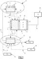
- Figure 1 schematically represents a device 1 comprising a positive electrode compartment 10 comprising a positive electrode 15 and a negative compartment electrode 20 comprising a negative electrode 25. On figure 1 , the power supply for device 1 electrolysis is not shown.
- the positive electrode compartment comprises an aqueous electrolyte medium 11 in which conductive carbon particles 12 circulating in the positive electrode compartment 10 are suspended.
- the conductive carbon particles 12 become positively charged in the positive electrode compartment 10.
- the negative electrode compartment 20 comprises an aqueous electrolyte medium 21 generating gaseous dihydrogen.
- the gaseous dihydrogen may be released through a pipe 61 for gas circulation and stored in a container 60.
- the electrolyte medium circulating in the positive electrode compartment 10 can be injected from a first storage container 40 via a fluid circulation line 42. Such first storage container 40 is located in the first zone 13.
- the electrolyte medium 11 circulating in the positive electrode compartment 10 can be directed from the positive electrode compartment 10 to a second storage container 50 via a fluid circulation line 51.
- the electrolytic medium 11 comprising the conductive carbon particles 12 can be recycled after discharge toward the first storage container 40 through a pipe 52 for fluidic circulation.
- the recycling of carbon 12 particles can be achieved by injection from the second reservoir 50 to the positive electrode compartment 10 via a fluid circulation line 53.
- the conductive carbon particles 12 are positively charged in the positive electrode compartment 10.
- the electrolytic medium 11 comprising the conductive carbon particles 12 is then directed through a pipe 54 for fluidic circulation to a first storage container 40.
- the charged 12 conductive carbon particles are discharged into the storage container 40 and/or 50, depending on the design.
- Asymmetric system generates H 2 in the cathodic compartment and stores energy electrostatically in the anodic compartment by flowing supercapacitive particles from a first zone having a storage container 40 to a second zone having a storage container 50.
- a basic electrolyte eg. KOH 5M
- the system consumes H 2 O at the cathode and generates OH - according to the reaction: 2H 2 O + 2 e - -> H 2 + 2 OH - . Therefore, an extra quantity of hydroxide ions (OH - ) is produced in the electrolyte and the positive electrode compartment 10 contains hydroxide ions.
- the charged supercapacitive particles are stored in the second storage container 50.
- Such second storage container 50 is located in the second zone 23. Therefore, the second storage container 50 and second zone 23 contain also hydroxide ions.
- CO 2 stored in a container 70 is injected through a pipe 71 in the second zone 23 in a controlled manner to create in presence of the hydroxide ions one or more deprotonated forms of carbonic acid.
- an alkali or alkaline earth metal salt, (for example CaCl 2) stored in a container 90 is injected through pipe 91 from said container 90 to the carbonation reactor 50 to provide solid carbonates XCO3 (typically CaCO 3 in case of CaCl 2 ) which can be stored in container 80.
- the carbonation reactor also works as or comprises a liquid/solid separator in order to separate the precipitated XCO 3 , for example CaCO 3 , from the liquid electrolyte.
- the storage container 50 and the carbonation rector 100 are separate devices preferably linked by one or more pipes 73 for fluidic circulation of the hydroxide ions from the second storage container 50 to the carbonation reactor 100. Accordingly, the injected CO 2 is trapped by the system via a carbonation reaction/process.
- the produced deprotonated form of carbonic acid or salt thereof can be stored in a container 80 downstream the second storage container 50 which are in fluidic communication via a pipe 72.
- the invention consists in a 2-step process :
- Figure 2 illustrates the behaviour of the negative electrode in linear voltammetry and the response of the positive electrode in cyclic voltammetry (calomel reference electrode).
- Figure 3 schematically represents a device 1 comprising a positive electrode compartment 10 comprising a positive electrode 15 and a negative compartment electrode 20 comprising a negative electrode 25. On figure 3 , the power supply for device 1 electrolysis is not shown. Such device 1 according to figure 3 is similar to a device 1 according to figure 1 , except the carbonation reactor is separate from the second storage container 50.
- CO 2 stored in a container 70 is injected through a pipe 71 in the second zone 23 in a controlled manner to create in presence of the hydroxide ions, one or more deprotonated forms of carbonic acid, which leads to the formation of an insoluble salt thereof (designated "XCO 3 ", wherein X is one or more alkali or alkaline earth metal, for example Ca, Mg, etc.) by carbonation reaction in the carbonation reactor 100, reducing at least in part the hydroxide ions concentration.
- the electrolytic medium 11 comprising the conductive carbon particles 12 can be recycled after discharge toward the first storage container 40 from the carbonation reactor 100 through a pipe 52 for fluidic circulation to the first storage container 40.
- the conductive carbon particles 12 are recirculated from the second storage container 50 to the first storage container 40 and the electrolyte 11 is recirculated through the carbonation reactor 100 to react with CO 2 prior to being recirculated to the first storage container 40.
- FIG. 4 schematically represents a device 1 comprising a positive electrode compartment 10 comprising a positive electrode 15 and a negative compartment electrode 20 comprising a negative electrode 25.
- the power supply for device 1 electrolysis is not shown.
- Such device 1 according to figure 4 is similar to a device 1 according to figure 3 , except electrolyte 11 of the positive electrode compartment 10 and electrolyte 21 of the negative compartment electrode 20 are not in contact and physically separated by membrane 30. Electrolytes 11 and 21 have separate circuit of circulation. Electrolyte 11 is from the first storage container 40 to the positive electrode compartment 10 and then to the second storage container 50. Electrolyte 11 can be recirculated back to the first storage container 40 from the second storage container 50.
- Electrolyte 21 is from the negative electrode compartment 20 to the carbonation reactor 100.
- CO 2 stored in a container 70 is injected through a pipe 71 in the reactor 100 in a controlled manner to create in presence of hydroxide ions, one or more deprotonated forms of carbonic acid which leads to the formation of an insoluble salt thereof (designated "XCO 3 ", wherein X is one or more alkali or alkaline earth metal, for example Ca, Mg, etc.) by carbonation reaction in the carbonation reactor 100, reducing at least in part the hydroxide ions concentration.
- XCO 3 an insoluble salt thereof
- Electrolyte 21 can be recirculated back to the negative electrode compartment 20 from the carbonation reactor 100 via the pipe 56.
- the particle size is classically defined by particle size analysis such as: dynamic light scattering (particles suspended in a liquid, typically water), or laser diffraction.
- the specific surface area (m2/g) of the particles is classically defined by nitrogen adsorption and BET analysis (Brunauer, Emmett and Teller).
- the capacities of the carbon electrodes are determined by potentiometry or cyclic voltammetry.
- the working electrode to be characterized is immersed in the electrolyte and is connected to a counter electrode (usually inert) via a potentiostat/galvanostat.
- a reference electrode e.g. calomel in an aqueous medium, is used to measure the change in its potential as a function of the charge carried between the working electrode and the counter-electrode.
- potentiometry a constant current is applied to the electrode, its potential increases linearly as a function of the load applied from its potential of zero charge to the maximum limit potential applied. The capacitance then corresponds to the inverse of the slope obtained.
- an electrochemical cell consists in :
- the apparent surface of both electrode is 1 cm 2 .
- the electrolyte is a KOH 5M solution.
- the carbon electrode is charged positively under polarization.
- the OH- ions of the electrolyte are attracted by the positive charge of the surface: an electrochemical double layer is formed at the electrode/electrolyte interface.
- the charge that is stored in the (+) capacitive electrode corresponds to the useful charge to generate H 2 .
- Q 1,35 C
- the finite charge of carbon (particles) is renewed thanks to an adapted flow.
- an electrochemical cell consists in :
- the apparent surface of electrode is still 1 cm 2 (as for example 1)
- Rate of carbon particles in the aqueous electrolyte 0.25 (solid / liquid mass ratio).
- Working current density is fixed at 100 mA/cm 2 .
- 2,4m 3 of KOH electrolyte is used.
- This extra quantity of OH- is regulated via the injection of CO 2 to recover the initial concentration at the entrance of the electrolyzer for a new cycle.
Landscapes
- Chemical & Material Sciences (AREA)
- Engineering & Computer Science (AREA)
- Chemical Kinetics & Catalysis (AREA)
- Electrochemistry (AREA)
- Materials Engineering (AREA)
- Metallurgy (AREA)
- Organic Chemistry (AREA)
- Inorganic Chemistry (AREA)
- Health & Medical Sciences (AREA)
- Biomedical Technology (AREA)
- Environmental & Geological Engineering (AREA)
- Analytical Chemistry (AREA)
- General Chemical & Material Sciences (AREA)
- Oil, Petroleum & Natural Gas (AREA)
- Life Sciences & Earth Sciences (AREA)
- Sustainable Development (AREA)
- Electrolytic Production Of Non-Metals, Compounds, Apparatuses Therefor (AREA)
Priority Applications (5)
| Application Number | Priority Date | Filing Date | Title |
|---|---|---|---|
| EP20306071.0A EP3971325A1 (fr) | 2020-09-21 | 2020-09-21 | Système de génération de h2 et de capture de co2 |
| EP21777547.7A EP4214353A1 (fr) | 2020-09-21 | 2021-09-21 | Système de génération de h2 et de capture de co2 |
| PCT/EP2021/075850 WO2022058600A1 (fr) | 2020-09-21 | 2021-09-21 | Système de génération de h2 et de capture de co2 |
| US18/026,886 US20240018671A1 (en) | 2020-09-21 | 2021-09-21 | System for h2 generation and co2 capture |
| CN202180064448.8A CN116322941A (zh) | 2020-09-21 | 2021-09-21 | 用于h2生成和co2捕集的系统 |
Applications Claiming Priority (1)
| Application Number | Priority Date | Filing Date | Title |
|---|---|---|---|
| EP20306071.0A EP3971325A1 (fr) | 2020-09-21 | 2020-09-21 | Système de génération de h2 et de capture de co2 |
Publications (1)
| Publication Number | Publication Date |
|---|---|
| EP3971325A1 true EP3971325A1 (fr) | 2022-03-23 |
Family
ID=72709271
Family Applications (2)
| Application Number | Title | Priority Date | Filing Date |
|---|---|---|---|
| EP20306071.0A Withdrawn EP3971325A1 (fr) | 2020-09-21 | 2020-09-21 | Système de génération de h2 et de capture de co2 |
| EP21777547.7A Pending EP4214353A1 (fr) | 2020-09-21 | 2021-09-21 | Système de génération de h2 et de capture de co2 |
Family Applications After (1)
| Application Number | Title | Priority Date | Filing Date |
|---|---|---|---|
| EP21777547.7A Pending EP4214353A1 (fr) | 2020-09-21 | 2021-09-21 | Système de génération de h2 et de capture de co2 |
Country Status (4)
| Country | Link |
|---|---|
| US (1) | US20240018671A1 (fr) |
| EP (2) | EP3971325A1 (fr) |
| CN (1) | CN116322941A (fr) |
| WO (1) | WO2022058600A1 (fr) |
Citations (5)
| Publication number | Priority date | Publication date | Assignee | Title |
|---|---|---|---|---|
| US20090169452A1 (en) * | 2007-12-28 | 2009-07-02 | Constantz Brent R | Methods of sequestering co2 |
| US20120183462A1 (en) * | 2007-08-09 | 2012-07-19 | Lawrence Livermore National Security, Llc | Electrochemical Production of Metal Hydroxide Using Metal Silicates |
| WO2017084589A1 (fr) | 2015-11-18 | 2017-05-26 | 复旦大学 | Procédé et dispositif pour produire de l'hydrogène par électrolyse de l'eau avec un procédé en deux étapes basé sur un système à trois électrodes |
| US20170306510A1 (en) * | 2014-11-19 | 2017-10-26 | Technion Research & Development Foundation Limited | Methods and system for hydrogen production by water electrolysis |
| WO2019193283A1 (fr) | 2018-04-03 | 2019-10-10 | Ergosup | Procede electrochimique de production d'hydrogene gazeux sous pression par electrolyse puis par conversion electrochimique |
-
2020
- 2020-09-21 EP EP20306071.0A patent/EP3971325A1/fr not_active Withdrawn
-
2021
- 2021-09-21 US US18/026,886 patent/US20240018671A1/en active Pending
- 2021-09-21 CN CN202180064448.8A patent/CN116322941A/zh active Pending
- 2021-09-21 EP EP21777547.7A patent/EP4214353A1/fr active Pending
- 2021-09-21 WO PCT/EP2021/075850 patent/WO2022058600A1/fr active Application Filing
Patent Citations (6)
| Publication number | Priority date | Publication date | Assignee | Title |
|---|---|---|---|---|
| US20120183462A1 (en) * | 2007-08-09 | 2012-07-19 | Lawrence Livermore National Security, Llc | Electrochemical Production of Metal Hydroxide Using Metal Silicates |
| US20090169452A1 (en) * | 2007-12-28 | 2009-07-02 | Constantz Brent R | Methods of sequestering co2 |
| US20170306510A1 (en) * | 2014-11-19 | 2017-10-26 | Technion Research & Development Foundation Limited | Methods and system for hydrogen production by water electrolysis |
| US20200040467A1 (en) | 2014-11-19 | 2020-02-06 | Technion Research & Development Foundation Limited | Methods and system for hydrogen production by water electrolysis |
| WO2017084589A1 (fr) | 2015-11-18 | 2017-05-26 | 复旦大学 | Procédé et dispositif pour produire de l'hydrogène par électrolyse de l'eau avec un procédé en deux étapes basé sur un système à trois électrodes |
| WO2019193283A1 (fr) | 2018-04-03 | 2019-10-10 | Ergosup | Procede electrochimique de production d'hydrogene gazeux sous pression par electrolyse puis par conversion electrochimique |
Non-Patent Citations (1)
| Title |
|---|
| K.B.HATZELLY. GOGOTSI ET AL., ELECTROCHIMICA ACTA, vol. 111, 2013, pages 888 - 897 |
Also Published As
| Publication number | Publication date |
|---|---|
| CN116322941A (zh) | 2023-06-23 |
| WO2022058600A1 (fr) | 2022-03-24 |
| EP4214353A1 (fr) | 2023-07-26 |
| US20240018671A1 (en) | 2024-01-18 |
Similar Documents
| Publication | Publication Date | Title |
|---|---|---|
| Chatenet et al. | Water electrolysis: from textbook knowledge to the latest scientific strategies and industrial developments | |
| Zhang et al. | Redox-mediated water splitting for decoupled H2 production | |
| US9518329B2 (en) | Method for electrochemically converting carbon dioxide | |
| US9217202B2 (en) | Membrane reactor | |
| US10854906B2 (en) | Redox flow battery with carbon dioxide based redox couple | |
| EP2823528B1 (fr) | Batterie à flux redox pour la génération d'hydrogène | |
| US20090045073A1 (en) | Electrolysis cell comprising sulfur dioxide-depolarized anode and method of using the same in hydrogen generation | |
| US20130118912A1 (en) | Compositions, Electrodes, Methods, and Systems for Water Electrolysis and Other Electrochemical Techniques | |
| Scott | Sustainable and green electrochemical science and technology | |
| US7282294B2 (en) | Hydrogen storage-based rechargeable fuel cell system and method | |
| JP6089188B2 (ja) | 第3電極を備えた水素製造装置および水素製造方法 | |
| US9145614B2 (en) | Membrane reactor | |
| US11050076B1 (en) | Flow cell systems, flow cell batteries, and hydrogen production processes | |
| WO2011028264A2 (fr) | Procédés et systèmes utilisant des matériaux et des électrodes pour l'électrolyse de l'eau, et autres techniques électrochimiques | |
| EP3971325A1 (fr) | Système de génération de h2 et de capture de co2 | |
| Shao et al. | Decoupled hydrogen and oxygen evolution for efficient water splitting by using nickel hydride batteries | |
| US20230332299A1 (en) | Water electrolysis device for hydrogen production | |
| JP3921300B2 (ja) | 水素発生装置 | |
| WO2023119779A1 (fr) | Procédé d'électrolyse de solution aqueuse | |
| US20230207851A1 (en) | Redox Ion Exchange Membranes and Applications Thereof | |
| Oraby et al. | Green Hydrogen Production Directly from Seawater with No Corrosion Using a Nonmetallic Electrode: A Novel Solution and a Proof of Concept | |
| Singh et al. | Water splitting via electrocatalysis and photocatalysis: Engineering stumbling blocks and advancements | |
| SE546000C2 (en) | Electrochemical system comprising two half-cells and method for electrochemical production of gas | |
| CN116815208A (zh) | 电解装置及电解装置的驱动方法 | |
| KR20230052610A (ko) | 신재생 에너지 및 연료 전지를 이용하는 복합 발전 시스템 및 이에 사용되는 수소 생산 시스템 |
Legal Events
| Date | Code | Title | Description |
|---|---|---|---|
| PUAI | Public reference made under article 153(3) epc to a published international application that has entered the european phase |
Free format text: ORIGINAL CODE: 0009012 |
|
| STAA | Information on the status of an ep patent application or granted ep patent |
Free format text: STATUS: THE APPLICATION HAS BEEN PUBLISHED |
|
| AK | Designated contracting states |
Kind code of ref document: A1 Designated state(s): AL AT BE BG CH CY CZ DE DK EE ES FI FR GB GR HR HU IE IS IT LI LT LU LV MC MK MT NL NO PL PT RO RS SE SI SK SM TR |
|
| RAP1 | Party data changed (applicant data changed or rights of an application transferred) |
Owner name: TOTALENERGIES ONETECH |
|
| STAA | Information on the status of an ep patent application or granted ep patent |
Free format text: STATUS: THE APPLICATION IS DEEMED TO BE WITHDRAWN |
|
| 18D | Application deemed to be withdrawn |
Effective date: 20220924 |