EP3970482B1 - Rollstuhl für vierbeiniges tier - Google Patents
Rollstuhl für vierbeiniges tier Download PDFInfo
- Publication number
- EP3970482B1 EP3970482B1 EP20850415.9A EP20850415A EP3970482B1 EP 3970482 B1 EP3970482 B1 EP 3970482B1 EP 20850415 A EP20850415 A EP 20850415A EP 3970482 B1 EP3970482 B1 EP 3970482B1
- Authority
- EP
- European Patent Office
- Prior art keywords
- legged animal
- legged
- wheel
- connecting wire
- ring frame
- Prior art date
- Legal status (The legal status is an assumption and is not a legal conclusion. Google has not performed a legal analysis and makes no representation as to the accuracy of the status listed.)
- Active
Links
Images


Classifications
-
- A—HUMAN NECESSITIES
- A61—MEDICAL OR VETERINARY SCIENCE; HYGIENE
- A61H—PHYSICAL THERAPY APPARATUS, e.g. DEVICES FOR LOCATING OR STIMULATING REFLEX POINTS IN THE BODY; ARTIFICIAL RESPIRATION; MASSAGE; BATHING DEVICES FOR SPECIAL THERAPEUTIC OR HYGIENIC PURPOSES OR SPECIFIC PARTS OF THE BODY
- A61H3/00—Appliances for aiding patients or disabled persons to walk about
- A61H3/04—Wheeled walking aids for patients or disabled persons
-
- A—HUMAN NECESSITIES
- A01—AGRICULTURE; FORESTRY; ANIMAL HUSBANDRY; HUNTING; TRAPPING; FISHING
- A01K—ANIMAL HUSBANDRY; AVICULTURE; APICULTURE; PISCICULTURE; FISHING; REARING OR BREEDING ANIMALS, NOT OTHERWISE PROVIDED FOR; NEW BREEDS OF ANIMALS
- A01K15/00—Devices for taming animals, e.g. nose-rings or hobbles; Devices for overturning animals in general; Training or exercising equipment; Covering boxes
- A01K15/02—Training or exercising equipment, e.g. mazes or labyrinths for animals ; Electric shock devices; Toys specially adapted for animals
-
- A—HUMAN NECESSITIES
- A61—MEDICAL OR VETERINARY SCIENCE; HYGIENE
- A61D—VETERINARY INSTRUMENTS, IMPLEMENTS, TOOLS, OR METHODS
- A61D9/00—Bandages, poultices, compresses specially adapted to veterinary purposes
-
- A—HUMAN NECESSITIES
- A61—MEDICAL OR VETERINARY SCIENCE; HYGIENE
- A61H—PHYSICAL THERAPY APPARATUS, e.g. DEVICES FOR LOCATING OR STIMULATING REFLEX POINTS IN THE BODY; ARTIFICIAL RESPIRATION; MASSAGE; BATHING DEVICES FOR SPECIAL THERAPEUTIC OR HYGIENIC PURPOSES OR SPECIFIC PARTS OF THE BODY
- A61H3/00—Appliances for aiding patients or disabled persons to walk about
- A61H3/008—Appliances for aiding patients or disabled persons to walk about using suspension devices for supporting the body in an upright walking or standing position, e.g. harnesses
-
- A—HUMAN NECESSITIES
- A61—MEDICAL OR VETERINARY SCIENCE; HYGIENE
- A61H—PHYSICAL THERAPY APPARATUS, e.g. DEVICES FOR LOCATING OR STIMULATING REFLEX POINTS IN THE BODY; ARTIFICIAL RESPIRATION; MASSAGE; BATHING DEVICES FOR SPECIAL THERAPEUTIC OR HYGIENIC PURPOSES OR SPECIFIC PARTS OF THE BODY
- A61H3/00—Appliances for aiding patients or disabled persons to walk about
- A61H2003/007—Appliances for aiding patients or disabled persons to walk about secured to the patient, e.g. with belts
-
- A—HUMAN NECESSITIES
- A61—MEDICAL OR VETERINARY SCIENCE; HYGIENE
- A61H—PHYSICAL THERAPY APPARATUS, e.g. DEVICES FOR LOCATING OR STIMULATING REFLEX POINTS IN THE BODY; ARTIFICIAL RESPIRATION; MASSAGE; BATHING DEVICES FOR SPECIAL THERAPEUTIC OR HYGIENIC PURPOSES OR SPECIFIC PARTS OF THE BODY
- A61H2203/00—Additional characteristics concerning the patient
- A61H2203/03—Additional characteristics concerning the patient especially adapted for animals
Definitions
- the present invention relates to a four-legged animal wheelchair for a four-legged animal (quadruped) that suffers walking difficulty because its forelimb or hindlimb is paralyzed or amputated or the like due to sickness or an accident and has insufficient motor function.
- Patent Literature 1 discloses a four-legged animal wheelchair that can be more comfortably used by a four-legged animal without interfering with the curving of the body when the four-legged animal turns directions with hindlimbs having an insufficient motor function due to sickness or an accident or the like (Patent Literature 1).
- Patent Literature 1 Japanese Patent Application Laid-Open No. 2015-70816
- Patent Applications DE10343357-A1 , US2013/104813-A1 and US5224444-A each disclose wheelchairs for four-legged animals.
- a four-legged animal that wears the conventional four-legged animal wheelchair forms a triangle with the tail or the head at the top and a line connecting the left and right wheels at the bottom.
- the belly or chest near an impaired limb keeps facing upward, limiting a movement of normal limbs that are supposed to trigger a standing motion. Consequently, the four-legged animal cannot stand up by itself and keeps struggling in a side-lying state, causing scratches on the elbow or knee.
- An object of the present invention is to provide a four-legged animal wheelchair that enables a four-legged animal that falls or the like and is placed into a side-lying state to stand up by itself.
- a four-legged animal wheelchair is a four-legged animal wheel chair used for a four-legged animal in order to solve the problem such that a four-legged animal that falls or the like and is placed in a side-lying state can stand up by itself, the four-legged animal wheelchair including: a ring frame attachable to the body of the four-legged animal near impaired limbs; a plurality of wheel support members that are slidably provided along the outer circumference of the ring frame and rotatably support wheels; and wheel displacement mechanisms for displacing, when the four-legged animal changes from an upright state to a side-lying state, a plurality of the wheels to positions in the upright state.
- the wheel displacement mechanism may include: a support shaft that is provided on the wheel support member and has the axis parallel to the axial direction of the ring frame; a swinging axle having a proximal end swingingly supported around the support shaft and a distal end that rotatably supports the wheel; a pinion gear fixed to the swinging axle; a swinging plate that is swingingly supported around the support shaft and has tooth spaces in engagement with the pinion gear; and stoppers that regulate the swinging range of the swinging axle and the swinging plate within a predetermined angle range.
- the wheel displacement mechanism may include: a support shaft that is provided on the wheel support member and has the axis parallel to the axial direction of the ring frame; a pair of swing arms, each having a proximal end swingingly supported around the support shaft and a distal end that rotatably supports the wheel; stoppers that regulate the swinging range of the swing arm within a predetermined angle range; an inner connecting wire connecting the inner sides of the swing arms; an outer connecting wire connecting the outer sides of the swing arms; a fall sensor for detecting a change of the four-legged animal from an upright state to a side-lying state; and a wire drive mechanism that reduces the tension of the inner connecting wire and pulls both ends of the outer connecting wire when the fall sensor detects the side-lying state of the four-legged animal.
- the wire drive mechanism may include two fixed pulleys spaced at a predetermined distance, a pair of traveling pulleys provided to reciprocate relative to the respective fixed pulleys, and drive motors for reciprocating the traveling pulleys, the inner connecting wire is wound around the first traveling pulley of the pair of traveling pulleys and the first fixed pulley, both ends of the inner connecting wire are connected to the inner side of the swing arm, the outer connecting wire is wound around the second traveling pulley and the second fixed pulley, and both ends of the outer connecting wire are connected to the outer side of the swing arm while being wound around the ring frame.
- the four-legged animal wheelchair may further include a lock mechanism for locking each of the wheel support members at a predetermined position on the ring frame when the four-legged animal stands up in an upright state, the lock mechanism unlocking the wheel support members while the wire drive mechanism swings the swing arms.
- the four-legged animal wheelchair may further include a holder or a saddle that is attachable to the body of the four-legged animal near normal limbs, a connecting frame connecting the holder or the saddle and the ring frame, and a fall sensor for detecting a change of the four-legged animal from an upright state to a side-lying state, wherein the connecting frame may be configured to elastically deform around rotating shafts in the lateral direction, the vertical direction, and the longitudinal direction with respect to the four-legged animal, and the connecting frame may include an elastic-force adjusting mechanism for reducing the elastic force of the connecting frame when the fall sensor detects the side-lying state of the four-legged animal.
- the present invention enables a four-legged animal that falls or the like and is placed into a side-lying state to stand up by itself.
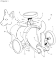
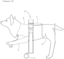
- a four-legged animal wheelchair 1A of the first embodiment is used for a four-legged animal that suffers walking difficulty because its hindlimbs are paralyzed or amputated or the like due to sickness or an accident and have insufficient motor function.
- the four-legged animal is a dog but is not limited thereto.
- the present invention is applicable to all animals walking with four legs. In the following description, indicated directions are shown by using the longitudinal direction, the lateral direction, and the vertical direction of a four-legged animal.
- the four-legged animal wheelchair 1A of the first embodiment mainly includes a ring frame 2 attachable to a body near impaired limbs, three wheel support members 3 slidably provided along the outer circumference of the ring frame 2, wheel displacement mechanisms 5 for displacing the wheels 4 to positions in an upright state, a holder 6 attachable to the front body part of a four-legged animal, and a connecting frame 7 connecting the holder 6 and the ring frame 2.
- the configurations will be described below.
- the ring frame 2 is attachable to the body of a four-legged animal near impaired limbs.
- the ring frame 2 is attached to the body near the hindlimbs.
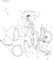
- the ring frame 2 is ring-shaped and has grooves 21 on the front end face and the rear end face along the circumferential direction as illustrated in Figure 2 .
- the ring frame 2 is divided into upper and lower parts as illustrated in Figure 2 .
- the upper and lower parts are configured to be connected via connecting fittings 22.
- a cushioning material (not illustrated) for reducing an impact to the body surface of the four-legged animal is attached to the inner surface of the ring frame 2.
- a saddle 8 for holding the body near the impaired limbs is connected to the lower end of the ring frame 2.
- impaired-limb covers 9 for holding impaired limbs are removably provided.
- the impaired-limb covers 9 are made of a flexible material and have an auxiliary wheel 91 at the lower ends.
- the wheel support members 3 are slidably provided along the outer circumference of the ring frame 2 and rotatably support the wheels 4.
- the wheel support members 3 each have a circumferential length that is determined by trisecting the circumference of the ring frame 2 as illustrated in Figure 2 .
- the claws 31 protruded inward are provided on the circumferential ends of the wheel support members 3.
- the wheel support members 3 are attached by inserting the claws 31 of the wheel support members 3 into the grooves 21 of the divided ring frames 2 and connecting the ring frames 2.
- the positional relationship of the three wheel support members 3 in the circumferential direction of the ring frames 2 is fixed by providing them so as to be in contact with one another.
- the configuration of the wheel support members 3 are not limited thereto and may be changed when necessary.
- the number of wheel support members 3 may be four or more.
- the positional relationship among the wheel support members 3 may be fixed by connecting the wheel support members 3 with a link frame or the like.
- the wheel displacement mechanism 5 displaces a plurality of the wheels 4 to positions in an upright state when the four-legged animal changes from an upright state to a side-lying state.
- the wheel displacement mechanism 5 is provided for each of the three wheel support members 3.
- the wheel displacement mechanism 5 includes a support shaft 51 that is provided on the wheel support member 3 and has the axis parallel to the axial direction of the ring frame 2, a swinging axle 52 having a proximal end swingingly supported around the support shaft 51 and a distal end that rotatably supports the wheel 4, a pinion gear 53 fixed to the swinging axle 52, a swinging plate 54 that is swingingly supported around the support shaft 51 and has tooth spaces in engagement with the pinion gear 53, and stoppers 55 that regulate the swinging range of the swinging axle 52 and the swinging plate 54 within a predetermined angle range.
- the stoppers 55 are provided such that the swinging axle 52 and the swinging plate 54 have a swinging range of about 60°.
- the stoppers 55 are not limited to this configuration. In other words, for a four-legged animal in an upright state, it is only necessary to regulate any two of the swinging axles 52 in a linear form substantially along the horizontal direction.
- the swinging plate 54 is substantially fan-shaped. The shape is not limited thereto.
- the holder 6 is attachable to the front body (chest) of the four-legged animal and is made of a flexible material.
- the holder 6 is divided into the upper and lower parts as illustrated in Figure 2 .
- the upper and lower parts can be connected with a hook-and-loop fastener or the like.
- the connecting frame 7 connects the holder 6 and the ring frame 2.
- the connecting frame 7 has the front end connected to the upper end of the holder 6 and the rear end connected to the upper end of the ring frame 2.
- the connecting frame 7 is configured to elastically deform around rotating shafts in the lateral direction, the vertical direction, and the longitudinal direction with respect to the four-legged animal.
- the connecting frame 7 includes a front member 71 swinging around a lateral rotating shaft 70a, an intermediate member 72 swinging around a vertical rotating shaft 70b, and a rear member 73 rotating around a longitudinal rotating shaft 70c that are connected to one another.
- coil springs 74 are provided to apply, in response to a swing or a rotation from a normal upright state, an elastic force in a direction that enables recovery to the normal state.
- the coil springs 74 are each configured to adjust an elastic force with a screw or the like.
- a fall sensor (not illustrated) for detecting a change of the four-legged animal from an upright state to a side-lying state is located without interfering with the ring frames 2 or the like. Additionally, an elastic-force adjusting mechanism 75 is provided to reduce the elastic force of the connecting frame 7 when the fall sensor detects the side-lying state of the four-legged animal.
- the elastic-force adjusting mechanism 75 is configured such that the tension of an adjusting wire 76 hung on the rear member 73 is adjusted by the forward and backward rotations of a tension adjusting motor 77. In a normal upright state, the tension of the adjusting wire 76 is increased to pull the rear member 73 backward and is brought into contact with a fixing member 78, thereby increasing the elastic force of the connecting frame 7.
- the fall sensor When the fall sensor detects the side-lying state of the four-legged animal, the rear member 73 is released from the fixing member 78 by reducing the tension of the adjusting wire 76. This reduces the elastic force of the connecting frame 7. Thus, even when the holder 6 near the normal limbs and the ring frames 2 near the impaired limbs are connected to each other, the four-legged animal in the side-lying state easily moves the normal limbs and stands up by itself.
- the fall sensor may be properly selected from mechanisms including a tilt sensor and a gyro sensor that can detect a change of the four-legged animal from an upright state to a side-lying state.
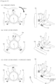
- the four-legged animal wheelchair 1A attached to a four-legged animal according to the first embodiment has wheels 4a and 4b laterally placed at the bottom in contact with the ground in a normal upright state, so that the swinging axles 52 of the wheels 4 come into contact with the upper stoppers 55 and are regulated in a linear form substantially along the horizontal direction.
- the left and right wheels 4a and 4b are rotatably supported at normal positions as substitutes for impaired limbs, enabling smooth walking only with normal limbs.
- the swinging plate 54 In the upright state, the swinging plate 54 is brought into contact with the lower stopper 55 by its own weight. Since an upper wheel 4c is placed in a free state, the upper wheel 4c may be directed upward as illustrated in Figure 4(a) or may be tilted in contact with one of the left and right stoppers 55.
- the wheel 4b When the four-legged animal falls or the like and is placed into a side-lying state, as illustrated in Figure 4(b) , the wheel 4b, one of the wheels in contact with the ground, and the upper wheel 4c separated from the ground are brought into contact with the ground. Furthermore, the swinging plate 54 is brought into contact with the pinion gear 53 that is on the lower side by its own weight. In the side-lying state, the belly of the four-legged animal is directed upward once.
- the ring frames 2 and the wheel support members 3 are configured to rotate relative to each other.
- the ring frames 2 attached to the rear body are smoothly rotated relative to the wheel support members 3 whose rotations are regulated by the wheels 4b and 4c that are in contact with the ground. This allows the rear body to follow the twisting motion of the front body, so that the four-legged animal stands up by itself in a normal upright state.
- the elastic-force adjusting mechanism 75 reduces the elastic force of the connecting frame 7.
- the left and right wheels 4b and 4c may remain diagonal to the ground as illustrated in Figure 4(b) .
- the wheel displacement mechanisms 5 displace the wheels 4b and 4c to positions in the upright state.
- the weight of the four-legged animal and the weight of the four-legged animal wheelchair 1A on the support shafts 51 are combined to swing the swinging axles 52 into contact with the upper stoppers 55.
- the swinging axles 52 of the wheels 4b and 4c are placed in a linear form substantially along the horizontal direction and return to positions in the normal upright state.
- the swinging plate 54 engaged with the pinion gear 53 is dragged upward with the swinging axle 52.
- the swinging plate 54 is swung toward the ground by its own weight.
- the first embodiment of the four-legged animal wheelchair 1A according to the present invention as described above achieves the following effects:
- a second embodiment of the four-legged animal wheelchair according to the present invention will be described below.
- the configurations identical or equivalent to those of the first embodiment described above are indicated by the same reference numerals, and a redundant explanation thereof is omitted.
- a four-legged animal wheelchair 1B according to the second embodiment features wheel displacement mechanisms 5 that are also suitable for a four-legged animal having long legs with a high center of gravity.
- the four-legged animal wheelchair 1B of the second embodiment is configured for hindlimbs as in the first embodiment and includes two wheel support members 3, 3 slidable along the outer circumference of ring frames 2. Between the wheel support members 3, a drive box 10 and a power-supply box 11 are slidably provided along the outer circumference of the ring frames 2.
- the drive box 10 contains a wire drive mechanism, which will be described later, and the power-supply box 11 supplies power to the drive box 10.
- the wheel displacement mechanism 5 is provided for each of the two wheel support members 3.
- the wheel displacement mechanism 5 includes a support shaft 51 that is provided in the wheel support member 3 and has the axis parallel to the axial direction of the ring frame 2, a pair of swing arms 56, 56 each having a proximal end swingingly supported around the support shaft 51 and a distal end that rotatably supports a wheel 4, stoppers 55 that regulate the swinging range of the swing arm 56 within a predetermined angle range, an inner connecting wire 57 connecting the inner sides of the swing arms 56, an outer connecting wire 58 connecting the outer sides of the swing arms 56, a fall sensor (not illustrated) for detecting a change of the four-legged animal from an upright state to a side-lying state, and a wire drive mechanism 59 that reduces the tension of the inner connecting wire 57 and pulls both ends of the outer connecting wire 58 when the fall sensor detects the side-lying state of the four-legged animal.
- the wire drive mechanism 59 is provided in the drive box 10 and includes two fixed pulleys 61, 61 spaced at a predetermined distance, a pair of traveling pulleys 62, 62 provided to reciprocate relative to the respective fixed pulleys 61, drive motors 63 for reciprocating the traveling pulleys 62, motor arms 64 fixed to the drive shafts of the drive motors 63, respectively, and traction belts 65 each of which connect the motor arm 64 and the traveling pulley 62.
- the inner connecting wire 57 is wound around the first traveling pulley 62 of the pair of traveling pulleys 62, 62 and the first fixed pulley 61, and both ends of the inner connecting wire 57 are connected to the inner side of the swing arm 56.
- the outer connecting wire 58 is wound around the second traveling pulley 62 and the second fixed pulley 61, and both ends of the outer connecting wire 58 are connected to the outer side of the swing arm 56 while being wound around the ring frame 2.
- the inner side and the outer side indicates an inner side and an outer side relative to the pair of swing arms 56, 56 in a normal upright state.
- the positional relationship between the swing arms 56 is laterally reversed each time the four-legged animal falls, so that the relationship between the inner side and the outer side is also reversed.
- a lock mechanism 80 is provided to lock each of the wheel support members 3 at a predetermined position on the ring frame 2 when the four-legged animal stands up in an upright state.
- the lock mechanism 80 unlocks the wheel support members 3 while the wire drive mechanism 59 swings the swing arms 56.
- the lock mechanism 80 includes a pair of through holes 81, 81 located at the base part of the wheel support member 3 with point symmetry with respect to the center of the support shaft 51, a pair of spring lock pins 82, 82 located on the inner surface and the outer surface of the swing arm 56 so as to pass through the through holes 81, and a locking hole 83 provided at a predetermined position on the outer surface of the ring frame 2, the spring lock pins 82 being insertable into and removable from the locking hole 83.
- one of the drive motors 63 winds up the traction belt 65 by using the motor arm 64 and holds the first traveling pulley 62 separated from the first fixed pulley 61 in a normal upright state.
- the swing arms 56 are pulled close to each other by the inner connecting wire 57 and are held in contact with the stoppers 55.
- the spring lock pin 82 provided on the inner side of the swing arm 56 is inserted into the locking hole 83 of the ring frame 2 while passing through the through hole 81 of the wheel support member 3.
- the sliding movements of the wheel support members 3 are regulated with respect to the ring frames 2, so that the wheel support members 3 are locked in a normal upright state.
- the spring lock pin 82 is not excessively pressed to the ring frame 2 by a spring elastic force.
- one of the drive motors 63 is placed into an idle state; meanwhile, the other drive motor 63 winds up the traction belt 65 by using the motor arm 64 and pulls the second traveling pulley 62 in a direction that separates from the second fixed pulley 61.
- the second traveling pulley 62 reaches the remotest position, the other drive motor 63 stops.
- the ring frames 2 attached to the rear body are smoothly rotated relative to the wheel support members 3 that are pulled inward by the inner connecting wire 57. This allows the rear body to follow the twisting motion of the front body, so that the four-legged animal stands up in a normal upright state.
- an elastic-force adjusting mechanism 75 reduces the elastic force of a connecting frame 7.
- the spring lock pin 82 provided on the inner side (the outer side before swinging) of the swing arm 56 is inserted into the locking hole 83 of the ring frame 2 while passing through the through hole 81 of the wheel support member 3.
- the sliding movements of the wheel support members 3 are regulated with respect to the ring frames 2, so that the wheel support members 3 are locked in a normal upright state.
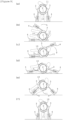
- a first-half process ( Figures 9(b) to 9(d) ), in which a large torque is not necessary for the traction of the swing arms 56, causes the drive motors 63 to wind up the traction belts 65 by using the motor arms 64, thereby quickly swinging and moving the swing arms 56.
- a second-half process ( Figures 9(d) to 9(f) ), in which a large torque is necessary for the traction of the swing arms 56, causes the drive motors 63 to wind up the traction belts 65 by using the proximal ends of the motor arms 64, thereby slowly swinging the swing arms 56 with a high torque. In this way, the winding speed and torque of the traction belt 65 are properly adjusted according to the steps of the displacing motions of the wheels 4.
- the second embodiment of the four-legged animal wheelchair as described above according to the present invention achieves, in addition to the effects of the first embodiment, the following effects:
- a third embodiment of the four-legged animal wheelchair according to the present invention will be described below.
- the configurations identical or equivalent to those of the foregoing embodiments are indicated by the same reference numerals, and a redundant explanation thereof is omitted.
- the first and second embodiments described the four-legged animal wheelchairs 1A and 1B for hindlimbs.
- a feature of a four-legged animal wheelchair 1C of the third embodiment is that the four-legged animal wheelchair 1B of the second embodiment is configured for forelimbs.
- ring frames 2 are provided on the rear end of a holder 6 attached to the front body of a four-legged animal.
- the ring frames 2 and a saddle 8 attached to the rear body of the four-legged animal are connected to each other via a connecting frame 7.
- the four-legged animal wheelchair according to the present invention is not limited to the foregoing embodiments and can be properly changed.
- the ring frames 2 are separably configured to facilitate the attachment and detachment of the four-legged animal wheelchair to and from the four-legged animal.
- the ring frames 2 may not be separable if the four-legged animal can easily wear and remove the wheelchair.
- an inner connecting wire 57 and an outer connecting wire 58 are separably configured but may not be separable.
- the holder 6 and the saddle 8 are attached near normal limbs and are connected to the ring frames 2 by using the connecting frame 7.
- the present invention is not limited to this configuration.
- the ring frames 2 firmly attachable near impaired limbs eliminate the need for providing the holder 6, the saddle 8, and the connecting frame 7.
- the saddle 8 is provided to hold the rear body, which is a body near impaired limbs.
- the present invention is not limited to this configuration.
- the configuration can be omitted depending upon the body shape of the four-legged animal.
- the rear body of the four-legged animal may be covered with an integral cover 12 that is a combination of a cushioning material and the impaired-limb covers 9, and the ring frames 2 may be fixed to the outer surface of the integral cover 12.
- the rod-like connecting frame 7 connects the holder 6 or the saddle 8 and the ring frames 2.
- the present invention is not limited to this configuration.
- the connection may be made via a spring member, e.g., a plate spring or a mesh-type net material 13 made of a flexible material as illustrated in Figure 12 .
Landscapes
- Health & Medical Sciences (AREA)
- Life Sciences & Earth Sciences (AREA)
- Veterinary Medicine (AREA)
- General Health & Medical Sciences (AREA)
- Animal Behavior & Ethology (AREA)
- Public Health (AREA)
- Physical Education & Sports Medicine (AREA)
- Epidemiology (AREA)
- Pain & Pain Management (AREA)
- Rehabilitation Therapy (AREA)
- Environmental Sciences (AREA)
- Zoology (AREA)
- Animal Husbandry (AREA)
- Biodiversity & Conservation Biology (AREA)
- Engineering & Computer Science (AREA)
- Wood Science & Technology (AREA)
- Handcart (AREA)
Claims (6)
- Rollstuhl für vierbeinige Lebewesen, der für ein vierbeiniges Lebewesen verwendet wird, gekennzeichnet durch:einen Ringrahmen, der an einem Körper des vierbeinigen Lebewesens in der Nähe von beeinträchtigten Gliedmaßen anbringbar ist;eine Vielzahl von Radstützelementen, die entlang eines Außenumfangs des Ringrahmens verschiebbar vorgesehen sind und Räder drehbar stützen; undRadversatzmechanismen, um dann, wenn das vierbeinige Lebewesen von einem aufrechten Zustand zu einem auf der Seite liegenden Zustand wechselt, eine Vielzahl der Räder zu Positionen im aufrechten Zustand zu versetzen.
- Rollstuhl für vierbeinige Lebewesen nach Anspruch 1, wobei der Radversatzmechanismus folgendes enthält:eine Stützwelle, die an dem Radstützelement vorgesehen ist und eine Achse parallel zu einer axialen Richtung des Ringrahmens hat;eine Schwingachse mit einem proximalen Ende, das um die Stützwelle herum schwingend gestützt ist, und einem distalen Ende, das das Rad drehbar stützt;ein Ritzel, das an der Schwingachse fixiert ist;eine Schwingplatte, die um die Stützwelle herum schwingend gestützt ist und Zahnlücken in Eingriff mit dem Ritzel hat; undStopper, die einen Schwingungsbereich der Schwingachse und der Schwingungsplatte innerhalb eines vorbestimmten Winkelbereichs regulieren.
- Rollstuhl für vierbeinige Lebewesen nach Anspruch 1, wobei der Radversatzmechanismus folgendes enthält:eine Stützwelle, die an dem Radstützelement vorgesehen ist und eine Achse parallel zu einer axialen Richtung des Ringrahmens hat;ein Paar von Schwingarmen, die jeweils ein proximales Ende, das um die Stützwelle schwingend gestützt ist, und ein distales Ende, das das Rad drehbar stützt, haben;Stopper, die einen Schwingungsbereich des Schwingarms innerhalb eines vorbestimmten Winkelbereichs regulieren;einen inneren Verbindungsdraht, der innere Seiten der Schwingarme verbindet;einen äußeren Verbindungsdraht, der äußere Seiten der Schwingarme verbindet;einen Sturzsensor zum Erkennen eines Wechsels des vierbeinigen Lebewesens vom aufrechten Zustand zu einem auf der Seite liegenden Zustand; undeinen Drahtantriebsmechanismus, der eine Spannung bzw. Zugkraft des inneren Verbindungsdrahts reduziert und beide Enden des äußeren Verbindungsdrahts zieht, wenn der Sturzsensor den auf der Seite liegenden Zustand des vierbeinigen Lebewesens erkennt.
- Rollstuhl für vierbeinige Lebewesen nach Anspruch 3, wobei der Drahtantriebsmechanismus zwei feste Rollen enthält, die mit einem vorbestimmten Abstand beabstandet sind, ein Paar von Laufrollen, die vorgesehen sind, um sich relativ zu den jeweiligen festen Rollen hin- und herzubewegen, und Antriebsmotoren zum Hin- und Herbewegen der Laufrollen, und
der innere Verbindungsdraht um die erste Laufrolle des Paars von Laufrollen und die erste feste Rolle gewickelt ist, beide Enden des inneren Verbindungsdrahts mit einer inneren Seite des Schwingarms verbunden sind, der äußere Verbindungsdraht um die zweite Laufrolle und die zweite feste Rolle gewickelt ist und beide Enden des äußeren Verbindungsdrahts mit einer äußeren Seite des Schwingarms verbunden sind, während sie um den Ringrahmen gewickelt sind. - Rollstuhl für vierbeinige Lebewesen nach Anspruch 3 oder 4, der weiterhin einen Verriegelungsmechanismus umfasst, um jedes der Radstützelemente bei einer vorbestimmten Position an dem Ringrahmen zu verriegeln, wenn das vierbeinige Lebewesen in einem aufrechten Zustand aufsteht, wobei der Verriegelungsmechanismus die Radstützelemente entriegelt, während der Drahtantriebsmechanismus die Schwingarme schwingt.
- Rollstuhl für vierbeinige Lebewesen nach einem der Ansprüche 1 bis 5, der weiterhin eine Halterung oder einen Sattel umfasst, die oder der an dem Körper des vierbeinigen Lebewesens in der Nähe von normalen Gliedmaßen anbringbar ist, einen Verbindungsrahmen, der die Halterung oder den Sattel und den Ringrahmen verbindet, und einen Sturzsensor zum Erkennen eines Wechselns des vierbeinigen Lebewesens von einem aufrechten Zustand zu einem auf der Seite liegenden Zustand,wobei der Verbindungsrahmen derart konfiguriert ist, dass er sich um Drehwellen herum in einer lateralen Richtung, einer vertikalen Richtung und einer longitudinalen Richtung in Bezug auf das vierbeinige Lebewesen elastisch verformt, undder Verbindungsrahmen einen Einstellmechanismus für elastische Kraft enthält, um eine elastische Kraft des Verbindungsrahmens zu reduzieren, wenn der Sturzsensor den auf der Seite liegenden Zustand des vierbeinigen Lebewesens erkennt.
Applications Claiming Priority (2)
| Application Number | Priority Date | Filing Date | Title |
|---|---|---|---|
| JP2019143476 | 2019-08-05 | ||
| PCT/JP2020/029594 WO2021024967A1 (ja) | 2019-08-05 | 2020-08-01 | 四足動物用車椅子 |
Publications (3)
| Publication Number | Publication Date |
|---|---|
| EP3970482A1 EP3970482A1 (de) | 2022-03-23 |
| EP3970482A4 EP3970482A4 (de) | 2022-07-20 |
| EP3970482B1 true EP3970482B1 (de) | 2023-07-26 |
Family
ID=74502643
Family Applications (1)
| Application Number | Title | Priority Date | Filing Date |
|---|---|---|---|
| EP20850415.9A Active EP3970482B1 (de) | 2019-08-05 | 2020-08-01 | Rollstuhl für vierbeiniges tier |
Country Status (4)
| Country | Link |
|---|---|
| US (1) | US11951068B2 (de) |
| EP (1) | EP3970482B1 (de) |
| JP (1) | JP6832605B1 (de) |
| WO (1) | WO2021024967A1 (de) |
Families Citing this family (8)
| Publication number | Priority date | Publication date | Assignee | Title |
|---|---|---|---|---|
| US11547091B1 (en) * | 2021-07-16 | 2023-01-10 | Thomas C. Cook | Animal mobility device |
| USD987917S1 (en) * | 2021-08-22 | 2023-05-30 | Nengfei Li | Adjustable pet wheelchair |
| USD987918S1 (en) * | 2021-08-23 | 2023-05-30 | Nengfei Li | Adjustable pet wheelchair |
| USD987921S1 (en) * | 2021-10-19 | 2023-05-30 | Nengfei Li | Adjustable pet wheelchair |
| US12133509B2 (en) | 2022-06-20 | 2024-11-05 | Sunteqnos Corporation | Wheelchair for quadrupedal animals |
| JP7492305B1 (ja) * | 2022-07-22 | 2024-05-29 | 洋明 是枝 | 四足動物用車椅子 |
| WO2025177953A1 (ja) * | 2024-02-20 | 2025-08-28 | 洋明 是枝 | 四足動物用車椅子 |
| USD1047314S1 (en) * | 2024-07-13 | 2024-10-15 | Jibo Tu | Pet wheelchair |
Family Cites Families (11)
| Publication number | Priority date | Publication date | Assignee | Title |
|---|---|---|---|---|
| GB9116481D0 (en) * | 1991-07-30 | 1991-09-11 | Hill Richard W | Improvements in or relating to walking aids for animals |
| US6820572B1 (en) * | 2003-05-23 | 2004-11-23 | Lincoln J. Parkes | Mobile prosthetic apparatus for disabled four-legged animals |
| DE10343357B4 (de) * | 2003-09-12 | 2017-04-06 | Thorsten Kiefer | Vorrichtung zur Entlastung und Stabilisierung von vierbeinigen Tierkörpern |
| JP3878609B2 (ja) * | 2004-02-20 | 2007-02-07 | 株式会社有薗製作所 | ペット用車椅子 |
| JP4244233B2 (ja) * | 2006-08-01 | 2009-03-25 | 延行 島岡 | ペット用車椅子 |
| US7549398B2 (en) * | 2007-10-18 | 2009-06-23 | Wheels For Pets, Llc | Adjustable wheelchair for pets |
| WO2012007935A2 (en) * | 2010-07-11 | 2012-01-19 | Nekuda D.M. Technologies And Design Ltd. | Walking aid for disabled four-legged animals |
| JP5460916B1 (ja) * | 2013-10-04 | 2014-04-02 | 康彰 大島 | 四足動物用車椅子 |
| ITUB20153031A1 (it) * | 2015-08-10 | 2017-02-10 | Amil S R L | Carrello di ausilio alla deambulazione di animali |
| KR20180110525A (ko) * | 2017-03-29 | 2018-10-10 | 이신호 | 애완동물용 보행 보조장치 |
| US20190209417A1 (en) * | 2018-01-05 | 2019-07-11 | Hui Chu Laicheng | Walking aid for pets with limb injury |
-
2020
- 2020-08-01 EP EP20850415.9A patent/EP3970482B1/de active Active
- 2020-08-01 WO PCT/JP2020/029594 patent/WO2021024967A1/ja not_active Ceased
- 2020-08-01 JP JP2020565998A patent/JP6832605B1/ja not_active Expired - Fee Related
-
2022
- 2022-01-07 US US17/571,442 patent/US11951068B2/en active Active
Also Published As
| Publication number | Publication date |
|---|---|
| WO2021024967A1 (ja) | 2021-02-11 |
| EP3970482A1 (de) | 2022-03-23 |
| US11951068B2 (en) | 2024-04-09 |
| US20220125664A1 (en) | 2022-04-28 |
| EP3970482A4 (de) | 2022-07-20 |
| JPWO2021024967A1 (ja) | 2021-09-13 |
| JP6832605B1 (ja) | 2021-02-24 |
Similar Documents
| Publication | Publication Date | Title |
|---|---|---|
| EP3970482B1 (de) | Rollstuhl für vierbeiniges tier | |
| US9554960B2 (en) | Wearable motion supporting device | |
| CN108697568B (zh) | 支撑结构 | |
| CN112168524A (zh) | 一种可实现坐立行三态转换的辅助移动轮椅外骨骼装置 | |
| CN102843991A (zh) | 四足动物的康复或运动帮助装置 | |
| CN110575366A (zh) | 一种主被动结合的下肢助力外骨骼机器人 | |
| JP4489880B2 (ja) | 玩具像の下肢を動かす機構 | |
| US20190175435A1 (en) | Muscular strength assisting apparatus | |
| CN110841245A (zh) | 一种适用于多模式的康复减重步行训练车 | |
| JP4979834B1 (ja) | 犬の歩行補助具 | |
| US20110257567A1 (en) | Motion assist device | |
| CN2831850Y (zh) | 可拖曳的袋子 | |
| JP5946203B1 (ja) | 膝補助装具 | |
| CN113398527A (zh) | 一种固定式多自由度机械臂减重下肢外骨骼康复机器人 | |
| CN108938223A (zh) | 一种可折叠的医疗急救担架 | |
| TW202128108A (zh) | 介助用裝置 | |
| CN212940468U (zh) | 一种刚柔耦合可穿戴式助行外骨骼系统 | |
| JP2018030183A (ja) | 動作補助装置 | |
| US9387145B2 (en) | Care support apparatus | |
| CN112022618A (zh) | 一种刚柔耦合可穿戴式助行外骨骼系统 | |
| CN213697396U (zh) | 一种骨折牵引装置 | |
| KR101478603B1 (ko) | 휠체어용 접이식 이동 발판 | |
| JP6296896B2 (ja) | ペット用車椅子 | |
| CN109620502B (zh) | 关节松动设备 | |
| US20080176720A1 (en) | Walking frame |
Legal Events
| Date | Code | Title | Description |
|---|---|---|---|
| STAA | Information on the status of an ep patent application or granted ep patent |
Free format text: STATUS: THE INTERNATIONAL PUBLICATION HAS BEEN MADE |
|
| PUAI | Public reference made under article 153(3) epc to a published international application that has entered the european phase |
Free format text: ORIGINAL CODE: 0009012 |
|
| STAA | Information on the status of an ep patent application or granted ep patent |
Free format text: STATUS: REQUEST FOR EXAMINATION WAS MADE |
|
| 17P | Request for examination filed |
Effective date: 20211213 |
|
| AK | Designated contracting states |
Kind code of ref document: A1 Designated state(s): AL AT BE BG CH CY CZ DE DK EE ES FI FR GB GR HR HU IE IS IT LI LT LU LV MC MK MT NL NO PL PT RO RS SE SI SK SM TR |
|
| A4 | Supplementary search report drawn up and despatched |
Effective date: 20220622 |
|
| RIC1 | Information provided on ipc code assigned before grant |
Ipc: A61H 3/04 20060101ALI20220615BHEP Ipc: A61D 9/00 20060101ALI20220615BHEP Ipc: A01K 15/02 20060101AFI20220615BHEP |
|
| DAV | Request for validation of the european patent (deleted) | ||
| DAX | Request for extension of the european patent (deleted) | ||
| GRAP | Despatch of communication of intention to grant a patent |
Free format text: ORIGINAL CODE: EPIDOSNIGR1 |
|
| STAA | Information on the status of an ep patent application or granted ep patent |
Free format text: STATUS: GRANT OF PATENT IS INTENDED |
|
| INTG | Intention to grant announced |
Effective date: 20230315 |
|
| GRAS | Grant fee paid |
Free format text: ORIGINAL CODE: EPIDOSNIGR3 |
|
| GRAA | (expected) grant |
Free format text: ORIGINAL CODE: 0009210 |
|
| STAA | Information on the status of an ep patent application or granted ep patent |
Free format text: STATUS: THE PATENT HAS BEEN GRANTED |
|
| P01 | Opt-out of the competence of the unified patent court (upc) registered |
Effective date: 20230519 |
|
| AK | Designated contracting states |
Kind code of ref document: B1 Designated state(s): AL AT BE BG CH CY CZ DE DK EE ES FI FR GB GR HR HU IE IS IT LI LT LU LV MC MK MT NL NO PL PT RO RS SE SI SK SM TR |
|
| REG | Reference to a national code |
Ref country code: CH Ref legal event code: EP |
|
| REG | Reference to a national code |
Ref country code: DE Ref legal event code: R096 Ref document number: 602020014654 Country of ref document: DE |
|
| REG | Reference to a national code |
Ref country code: IE Ref legal event code: FG4D |
|
| REG | Reference to a national code |
Ref country code: LT Ref legal event code: MG9D |
|
| REG | Reference to a national code |
Ref country code: NL Ref legal event code: MP Effective date: 20230726 |
|
| PGFP | Annual fee paid to national office [announced via postgrant information from national office to epo] |
Ref country code: FR Payment date: 20230823 Year of fee payment: 4 Ref country code: DE Payment date: 20230831 Year of fee payment: 4 |
|
| REG | Reference to a national code |
Ref country code: AT Ref legal event code: MK05 Ref document number: 1590839 Country of ref document: AT Kind code of ref document: T Effective date: 20230726 |
|
| PG25 | Lapsed in a contracting state [announced via postgrant information from national office to epo] |
Ref country code: NL Free format text: LAPSE BECAUSE OF FAILURE TO SUBMIT A TRANSLATION OF THE DESCRIPTION OR TO PAY THE FEE WITHIN THE PRESCRIBED TIME-LIMIT Effective date: 20230726 |
|
| PG25 | Lapsed in a contracting state [announced via postgrant information from national office to epo] |
Ref country code: GR Free format text: LAPSE BECAUSE OF FAILURE TO SUBMIT A TRANSLATION OF THE DESCRIPTION OR TO PAY THE FEE WITHIN THE PRESCRIBED TIME-LIMIT Effective date: 20231027 |
|
| PG25 | Lapsed in a contracting state [announced via postgrant information from national office to epo] |
Ref country code: IS Free format text: LAPSE BECAUSE OF FAILURE TO SUBMIT A TRANSLATION OF THE DESCRIPTION OR TO PAY THE FEE WITHIN THE PRESCRIBED TIME-LIMIT Effective date: 20231126 |
|
| PG25 | Lapsed in a contracting state [announced via postgrant information from national office to epo] |
Ref country code: SE Free format text: LAPSE BECAUSE OF FAILURE TO SUBMIT A TRANSLATION OF THE DESCRIPTION OR TO PAY THE FEE WITHIN THE PRESCRIBED TIME-LIMIT Effective date: 20230726 Ref country code: RS Free format text: LAPSE BECAUSE OF FAILURE TO SUBMIT A TRANSLATION OF THE DESCRIPTION OR TO PAY THE FEE WITHIN THE PRESCRIBED TIME-LIMIT Effective date: 20230726 Ref country code: PT Free format text: LAPSE BECAUSE OF FAILURE TO SUBMIT A TRANSLATION OF THE DESCRIPTION OR TO PAY THE FEE WITHIN THE PRESCRIBED TIME-LIMIT Effective date: 20231127 Ref country code: NO Free format text: LAPSE BECAUSE OF FAILURE TO SUBMIT A TRANSLATION OF THE DESCRIPTION OR TO PAY THE FEE WITHIN THE PRESCRIBED TIME-LIMIT Effective date: 20231026 Ref country code: LV Free format text: LAPSE BECAUSE OF FAILURE TO SUBMIT A TRANSLATION OF THE DESCRIPTION OR TO PAY THE FEE WITHIN THE PRESCRIBED TIME-LIMIT Effective date: 20230726 Ref country code: LT Free format text: LAPSE BECAUSE OF FAILURE TO SUBMIT A TRANSLATION OF THE DESCRIPTION OR TO PAY THE FEE WITHIN THE PRESCRIBED TIME-LIMIT Effective date: 20230726 Ref country code: IS Free format text: LAPSE BECAUSE OF FAILURE TO SUBMIT A TRANSLATION OF THE DESCRIPTION OR TO PAY THE FEE WITHIN THE PRESCRIBED TIME-LIMIT Effective date: 20231126 Ref country code: HR Free format text: LAPSE BECAUSE OF FAILURE TO SUBMIT A TRANSLATION OF THE DESCRIPTION OR TO PAY THE FEE WITHIN THE PRESCRIBED TIME-LIMIT Effective date: 20230726 Ref country code: GR Free format text: LAPSE BECAUSE OF FAILURE TO SUBMIT A TRANSLATION OF THE DESCRIPTION OR TO PAY THE FEE WITHIN THE PRESCRIBED TIME-LIMIT Effective date: 20231027 Ref country code: FI Free format text: LAPSE BECAUSE OF FAILURE TO SUBMIT A TRANSLATION OF THE DESCRIPTION OR TO PAY THE FEE WITHIN THE PRESCRIBED TIME-LIMIT Effective date: 20230726 Ref country code: AT Free format text: LAPSE BECAUSE OF FAILURE TO SUBMIT A TRANSLATION OF THE DESCRIPTION OR TO PAY THE FEE WITHIN THE PRESCRIBED TIME-LIMIT Effective date: 20230726 |
|
| PG25 | Lapsed in a contracting state [announced via postgrant information from national office to epo] |
Ref country code: PL Free format text: LAPSE BECAUSE OF FAILURE TO SUBMIT A TRANSLATION OF THE DESCRIPTION OR TO PAY THE FEE WITHIN THE PRESCRIBED TIME-LIMIT Effective date: 20230726 |
|
| REG | Reference to a national code |
Ref country code: CH Ref legal event code: PL |
|
| PG25 | Lapsed in a contracting state [announced via postgrant information from national office to epo] |
Ref country code: LU Free format text: LAPSE BECAUSE OF NON-PAYMENT OF DUE FEES Effective date: 20230801 |
|
| PG25 | Lapsed in a contracting state [announced via postgrant information from national office to epo] |
Ref country code: ES Free format text: LAPSE BECAUSE OF FAILURE TO SUBMIT A TRANSLATION OF THE DESCRIPTION OR TO PAY THE FEE WITHIN THE PRESCRIBED TIME-LIMIT Effective date: 20230726 |
|
| REG | Reference to a national code |
Ref country code: DE Ref legal event code: R097 Ref document number: 602020014654 Country of ref document: DE |
|
| PG25 | Lapsed in a contracting state [announced via postgrant information from national office to epo] |
Ref country code: SM Free format text: LAPSE BECAUSE OF FAILURE TO SUBMIT A TRANSLATION OF THE DESCRIPTION OR TO PAY THE FEE WITHIN THE PRESCRIBED TIME-LIMIT Effective date: 20230726 Ref country code: RO Free format text: LAPSE BECAUSE OF FAILURE TO SUBMIT A TRANSLATION OF THE DESCRIPTION OR TO PAY THE FEE WITHIN THE PRESCRIBED TIME-LIMIT Effective date: 20230726 Ref country code: LU Free format text: LAPSE BECAUSE OF NON-PAYMENT OF DUE FEES Effective date: 20230801 Ref country code: ES Free format text: LAPSE BECAUSE OF FAILURE TO SUBMIT A TRANSLATION OF THE DESCRIPTION OR TO PAY THE FEE WITHIN THE PRESCRIBED TIME-LIMIT Effective date: 20230726 Ref country code: EE Free format text: LAPSE BECAUSE OF FAILURE TO SUBMIT A TRANSLATION OF THE DESCRIPTION OR TO PAY THE FEE WITHIN THE PRESCRIBED TIME-LIMIT Effective date: 20230726 Ref country code: DK Free format text: LAPSE BECAUSE OF FAILURE TO SUBMIT A TRANSLATION OF THE DESCRIPTION OR TO PAY THE FEE WITHIN THE PRESCRIBED TIME-LIMIT Effective date: 20230726 Ref country code: CZ Free format text: LAPSE BECAUSE OF FAILURE TO SUBMIT A TRANSLATION OF THE DESCRIPTION OR TO PAY THE FEE WITHIN THE PRESCRIBED TIME-LIMIT Effective date: 20230726 Ref country code: SK Free format text: LAPSE BECAUSE OF FAILURE TO SUBMIT A TRANSLATION OF THE DESCRIPTION OR TO PAY THE FEE WITHIN THE PRESCRIBED TIME-LIMIT Effective date: 20230726 Ref country code: CH Free format text: LAPSE BECAUSE OF NON-PAYMENT OF DUE FEES Effective date: 20230831 Ref country code: MC Free format text: LAPSE BECAUSE OF FAILURE TO SUBMIT A TRANSLATION OF THE DESCRIPTION OR TO PAY THE FEE WITHIN THE PRESCRIBED TIME-LIMIT Effective date: 20230726 |
|
| REG | Reference to a national code |
Ref country code: BE Ref legal event code: MM Effective date: 20230831 |
|
| REG | Reference to a national code |
Ref country code: IE Ref legal event code: MM4A |
|
| PG25 | Lapsed in a contracting state [announced via postgrant information from national office to epo] |
Ref country code: IT Free format text: LAPSE BECAUSE OF FAILURE TO SUBMIT A TRANSLATION OF THE DESCRIPTION OR TO PAY THE FEE WITHIN THE PRESCRIBED TIME-LIMIT Effective date: 20230726 |
|
| PLBE | No opposition filed within time limit |
Free format text: ORIGINAL CODE: 0009261 |
|
| STAA | Information on the status of an ep patent application or granted ep patent |
Free format text: STATUS: NO OPPOSITION FILED WITHIN TIME LIMIT |
|
| 26N | No opposition filed |
Effective date: 20240429 |
|
| PG25 | Lapsed in a contracting state [announced via postgrant information from national office to epo] |
Ref country code: IE Free format text: LAPSE BECAUSE OF NON-PAYMENT OF DUE FEES Effective date: 20230801 |
|
| PG25 | Lapsed in a contracting state [announced via postgrant information from national office to epo] |
Ref country code: IE Free format text: LAPSE BECAUSE OF NON-PAYMENT OF DUE FEES Effective date: 20230801 Ref country code: SI Free format text: LAPSE BECAUSE OF FAILURE TO SUBMIT A TRANSLATION OF THE DESCRIPTION OR TO PAY THE FEE WITHIN THE PRESCRIBED TIME-LIMIT Effective date: 20230726 |
|
| PG25 | Lapsed in a contracting state [announced via postgrant information from national office to epo] |
Ref country code: BE Free format text: LAPSE BECAUSE OF NON-PAYMENT OF DUE FEES Effective date: 20230831 |
|
| PG25 | Lapsed in a contracting state [announced via postgrant information from national office to epo] |
Ref country code: BG Free format text: LAPSE BECAUSE OF FAILURE TO SUBMIT A TRANSLATION OF THE DESCRIPTION OR TO PAY THE FEE WITHIN THE PRESCRIBED TIME-LIMIT Effective date: 20230726 |
|
| PG25 | Lapsed in a contracting state [announced via postgrant information from national office to epo] |
Ref country code: BG Free format text: LAPSE BECAUSE OF FAILURE TO SUBMIT A TRANSLATION OF THE DESCRIPTION OR TO PAY THE FEE WITHIN THE PRESCRIBED TIME-LIMIT Effective date: 20230726 |
|
| REG | Reference to a national code |
Ref country code: DE Ref legal event code: R119 Ref document number: 602020014654 Country of ref document: DE |
|
| GBPC | Gb: european patent ceased through non-payment of renewal fee |
Effective date: 20240801 |
|
| PG25 | Lapsed in a contracting state [announced via postgrant information from national office to epo] |
Ref country code: DE Free format text: LAPSE BECAUSE OF NON-PAYMENT OF DUE FEES Effective date: 20250301 |
|
| PG25 | Lapsed in a contracting state [announced via postgrant information from national office to epo] |
Ref country code: GB Free format text: LAPSE BECAUSE OF NON-PAYMENT OF DUE FEES Effective date: 20240801 |
|
| PG25 | Lapsed in a contracting state [announced via postgrant information from national office to epo] |
Ref country code: FR Free format text: LAPSE BECAUSE OF NON-PAYMENT OF DUE FEES Effective date: 20240831 |
|
| PG25 | Lapsed in a contracting state [announced via postgrant information from national office to epo] |
Ref country code: CY Free format text: LAPSE BECAUSE OF FAILURE TO SUBMIT A TRANSLATION OF THE DESCRIPTION OR TO PAY THE FEE WITHIN THE PRESCRIBED TIME-LIMIT; INVALID AB INITIO Effective date: 20200801 |
|
| PG25 | Lapsed in a contracting state [announced via postgrant information from national office to epo] |
Ref country code: HU Free format text: LAPSE BECAUSE OF FAILURE TO SUBMIT A TRANSLATION OF THE DESCRIPTION OR TO PAY THE FEE WITHIN THE PRESCRIBED TIME-LIMIT; INVALID AB INITIO Effective date: 20200801 |
|
| PG25 | Lapsed in a contracting state [announced via postgrant information from national office to epo] |
Ref country code: TR Free format text: LAPSE BECAUSE OF FAILURE TO SUBMIT A TRANSLATION OF THE DESCRIPTION OR TO PAY THE FEE WITHIN THE PRESCRIBED TIME-LIMIT Effective date: 20230726 |