EP3969795B1 - Anschlussvorrichtung - Google Patents
Anschlussvorrichtung Download PDFInfo
- Publication number
- EP3969795B1 EP3969795B1 EP20731550.8A EP20731550A EP3969795B1 EP 3969795 B1 EP3969795 B1 EP 3969795B1 EP 20731550 A EP20731550 A EP 20731550A EP 3969795 B1 EP3969795 B1 EP 3969795B1
- Authority
- EP
- European Patent Office
- Prior art keywords
- clamping
- elongate member
- flexible elongate
- carriage
- arrangement
- Prior art date
- Legal status (The legal status is an assumption and is not a legal conclusion. Google has not performed a legal analysis and makes no representation as to the accuracy of the status listed.)
- Active
Links
Images


Classifications
-
- F—MECHANICAL ENGINEERING; LIGHTING; HEATING; WEAPONS; BLASTING
- F16—ENGINEERING ELEMENTS AND UNITS; GENERAL MEASURES FOR PRODUCING AND MAINTAINING EFFECTIVE FUNCTIONING OF MACHINES OR INSTALLATIONS; THERMAL INSULATION IN GENERAL
- F16L—PIPES; JOINTS OR FITTINGS FOR PIPES; SUPPORTS FOR PIPES, CABLES OR PROTECTIVE TUBING; MEANS FOR THERMAL INSULATION IN GENERAL
- F16L3/00—Supports for pipes, cables or protective tubing, e.g. hangers, holders, clamps, cleats, clips, brackets
- F16L3/24—Supports for pipes, cables or protective tubing, e.g. hangers, holders, clamps, cleats, clips, brackets with special member for attachment to profiled girders
-
- F—MECHANICAL ENGINEERING; LIGHTING; HEATING; WEAPONS; BLASTING
- F16—ENGINEERING ELEMENTS AND UNITS; GENERAL MEASURES FOR PRODUCING AND MAINTAINING EFFECTIVE FUNCTIONING OF MACHINES OR INSTALLATIONS; THERMAL INSULATION IN GENERAL
- F16B—DEVICES FOR FASTENING OR SECURING CONSTRUCTIONAL ELEMENTS OR MACHINE PARTS TOGETHER, e.g. NAILS, BOLTS, CIRCLIPS, CLAMPS, CLIPS OR WEDGES; JOINTS OR JOINTING
- F16B19/00—Bolts without screw-thread; Pins, including deformable elements; Rivets
- F16B19/02—Bolts or sleeves for positioning of machine parts, e.g. notched taper pins, fitting pins, sleeves, eccentric positioning rings
-
- F—MECHANICAL ENGINEERING; LIGHTING; HEATING; WEAPONS; BLASTING
- F16—ENGINEERING ELEMENTS AND UNITS; GENERAL MEASURES FOR PRODUCING AND MAINTAINING EFFECTIVE FUNCTIONING OF MACHINES OR INSTALLATIONS; THERMAL INSULATION IN GENERAL
- F16B—DEVICES FOR FASTENING OR SECURING CONSTRUCTIONAL ELEMENTS OR MACHINE PARTS TOGETHER, e.g. NAILS, BOLTS, CIRCLIPS, CLAMPS, CLIPS OR WEDGES; JOINTS OR JOINTING
- F16B2/00—Friction-grip releasable fastenings
- F16B2/02—Clamps, i.e. with gripping action effected by positive means other than the inherent resistance to deformation of the material of the fastening
- F16B2/06—Clamps, i.e. with gripping action effected by positive means other than the inherent resistance to deformation of the material of the fastening external, i.e. with contracting action
- F16B2/08—Clamps, i.e. with gripping action effected by positive means other than the inherent resistance to deformation of the material of the fastening external, i.e. with contracting action using bands
-
- F—MECHANICAL ENGINEERING; LIGHTING; HEATING; WEAPONS; BLASTING
- F16—ENGINEERING ELEMENTS AND UNITS; GENERAL MEASURES FOR PRODUCING AND MAINTAINING EFFECTIVE FUNCTIONING OF MACHINES OR INSTALLATIONS; THERMAL INSULATION IN GENERAL
- F16B—DEVICES FOR FASTENING OR SECURING CONSTRUCTIONAL ELEMENTS OR MACHINE PARTS TOGETHER, e.g. NAILS, BOLTS, CIRCLIPS, CLAMPS, CLIPS OR WEDGES; JOINTS OR JOINTING
- F16B21/00—Means for preventing relative axial movement of a pin, spigot, shaft or the like and a member surrounding it; Stud-and-socket releasable fastenings
- F16B21/02—Releasable fastening devices locking by rotation
-
- F—MECHANICAL ENGINEERING; LIGHTING; HEATING; WEAPONS; BLASTING
- F16—ENGINEERING ELEMENTS AND UNITS; GENERAL MEASURES FOR PRODUCING AND MAINTAINING EFFECTIVE FUNCTIONING OF MACHINES OR INSTALLATIONS; THERMAL INSULATION IN GENERAL
- F16B—DEVICES FOR FASTENING OR SECURING CONSTRUCTIONAL ELEMENTS OR MACHINE PARTS TOGETHER, e.g. NAILS, BOLTS, CIRCLIPS, CLAMPS, CLIPS OR WEDGES; JOINTS OR JOINTING
- F16B37/00—Nuts or like thread-engaging members
- F16B37/04—Devices for fastening nuts to surfaces, e.g. sheets, plates
- F16B37/045—Devices for fastening nuts to surfaces, e.g. sheets, plates specially adapted for fastening in channels, e.g. sliding bolts, channel nuts
- F16B37/046—Devices for fastening nuts to surfaces, e.g. sheets, plates specially adapted for fastening in channels, e.g. sliding bolts, channel nuts with resilient means for urging the nut inside the channel
-
- F—MECHANICAL ENGINEERING; LIGHTING; HEATING; WEAPONS; BLASTING
- F16—ENGINEERING ELEMENTS AND UNITS; GENERAL MEASURES FOR PRODUCING AND MAINTAINING EFFECTIVE FUNCTIONING OF MACHINES OR INSTALLATIONS; THERMAL INSULATION IN GENERAL
- F16G—BELTS, CABLES, OR ROPES, PREDOMINANTLY USED FOR DRIVING PURPOSES; CHAINS; FITTINGS PREDOMINANTLY USED THEREFOR
- F16G11/00—Means for fastening cables or ropes to one another or to other objects; Caps or sleeves for fixing on cables or ropes
- F16G11/10—Quick-acting fastenings; Clamps holding in one direction only
- F16G11/105—Clamps holding in one direction only
- F16G11/106—Clamps holding in one direction only using a toothed surface
-
- F—MECHANICAL ENGINEERING; LIGHTING; HEATING; WEAPONS; BLASTING
- F16—ENGINEERING ELEMENTS AND UNITS; GENERAL MEASURES FOR PRODUCING AND MAINTAINING EFFECTIVE FUNCTIONING OF MACHINES OR INSTALLATIONS; THERMAL INSULATION IN GENERAL
- F16L—PIPES; JOINTS OR FITTINGS FOR PIPES; SUPPORTS FOR PIPES, CABLES OR PROTECTIVE TUBING; MEANS FOR THERMAL INSULATION IN GENERAL
- F16L3/00—Supports for pipes, cables or protective tubing, e.g. hangers, holders, clamps, cleats, clips, brackets
- F16L3/02—Supports for pipes, cables or protective tubing, e.g. hangers, holders, clamps, cleats, clips, brackets partly surrounding the pipes, cables or protective tubing
- F16L3/04—Supports for pipes, cables or protective tubing, e.g. hangers, holders, clamps, cleats, clips, brackets partly surrounding the pipes, cables or protective tubing and pressing it against a wall or other support
-
- F—MECHANICAL ENGINEERING; LIGHTING; HEATING; WEAPONS; BLASTING
- F16—ENGINEERING ELEMENTS AND UNITS; GENERAL MEASURES FOR PRODUCING AND MAINTAINING EFFECTIVE FUNCTIONING OF MACHINES OR INSTALLATIONS; THERMAL INSULATION IN GENERAL
- F16L—PIPES; JOINTS OR FITTINGS FOR PIPES; SUPPORTS FOR PIPES, CABLES OR PROTECTIVE TUBING; MEANS FOR THERMAL INSULATION IN GENERAL
- F16L3/00—Supports for pipes, cables or protective tubing, e.g. hangers, holders, clamps, cleats, clips, brackets
- F16L3/08—Supports for pipes, cables or protective tubing, e.g. hangers, holders, clamps, cleats, clips, brackets substantially surrounding the pipe, cable or protective tubing
- F16L3/10—Supports for pipes, cables or protective tubing, e.g. hangers, holders, clamps, cleats, clips, brackets substantially surrounding the pipe, cable or protective tubing divided, i.e. with two members engaging the pipe, cable or protective tubing
- F16L3/1058—Supports for pipes, cables or protective tubing, e.g. hangers, holders, clamps, cleats, clips, brackets substantially surrounding the pipe, cable or protective tubing divided, i.e. with two members engaging the pipe, cable or protective tubing one member being flexible or elastic
-
- F—MECHANICAL ENGINEERING; LIGHTING; HEATING; WEAPONS; BLASTING
- F16—ENGINEERING ELEMENTS AND UNITS; GENERAL MEASURES FOR PRODUCING AND MAINTAINING EFFECTIVE FUNCTIONING OF MACHINES OR INSTALLATIONS; THERMAL INSULATION IN GENERAL
- F16L—PIPES; JOINTS OR FITTINGS FOR PIPES; SUPPORTS FOR PIPES, CABLES OR PROTECTIVE TUBING; MEANS FOR THERMAL INSULATION IN GENERAL
- F16L3/00—Supports for pipes, cables or protective tubing, e.g. hangers, holders, clamps, cleats, clips, brackets
- F16L3/08—Supports for pipes, cables or protective tubing, e.g. hangers, holders, clamps, cleats, clips, brackets substantially surrounding the pipe, cable or protective tubing
- F16L3/12—Supports for pipes, cables or protective tubing, e.g. hangers, holders, clamps, cleats, clips, brackets substantially surrounding the pipe, cable or protective tubing comprising a member substantially surrounding the pipe, cable or protective tubing
- F16L3/137—Supports for pipes, cables or protective tubing, e.g. hangers, holders, clamps, cleats, clips, brackets substantially surrounding the pipe, cable or protective tubing comprising a member substantially surrounding the pipe, cable or protective tubing and consisting of a flexible band
-
- F—MECHANICAL ENGINEERING; LIGHTING; HEATING; WEAPONS; BLASTING
- F16—ENGINEERING ELEMENTS AND UNITS; GENERAL MEASURES FOR PRODUCING AND MAINTAINING EFFECTIVE FUNCTIONING OF MACHINES OR INSTALLATIONS; THERMAL INSULATION IN GENERAL
- F16L—PIPES; JOINTS OR FITTINGS FOR PIPES; SUPPORTS FOR PIPES, CABLES OR PROTECTIVE TUBING; MEANS FOR THERMAL INSULATION IN GENERAL
- F16L3/00—Supports for pipes, cables or protective tubing, e.g. hangers, holders, clamps, cleats, clips, brackets
- F16L3/24—Supports for pipes, cables or protective tubing, e.g. hangers, holders, clamps, cleats, clips, brackets with special member for attachment to profiled girders
- F16L3/243—Supports for pipes, cables or protective tubing, e.g. hangers, holders, clamps, cleats, clips, brackets with special member for attachment to profiled girders the special member being inserted in the profiled girder
- F16L3/2431—Supports for pipes, cables or protective tubing, e.g. hangers, holders, clamps, cleats, clips, brackets with special member for attachment to profiled girders the special member being inserted in the profiled girder the special member being inserted and subsequently rotated to a limited extent
-
- F—MECHANICAL ENGINEERING; LIGHTING; HEATING; WEAPONS; BLASTING
- F16—ENGINEERING ELEMENTS AND UNITS; GENERAL MEASURES FOR PRODUCING AND MAINTAINING EFFECTIVE FUNCTIONING OF MACHINES OR INSTALLATIONS; THERMAL INSULATION IN GENERAL
- F16M—FRAMES, CASINGS OR BEDS OF ENGINES, MACHINES OR APPARATUS, NOT SPECIFIC TO ENGINES, MACHINES OR APPARATUS PROVIDED FOR ELSEWHERE; STANDS; SUPPORTS
- F16M11/00—Stands or trestles as supports for apparatus or articles placed thereon ; Stands for scientific apparatus such as gravitational force meters
- F16M11/02—Heads
- F16M11/04—Means for attachment of apparatus; Means allowing adjustment of the apparatus relatively to the stand
- F16M11/041—Allowing quick release of the apparatus
-
- F—MECHANICAL ENGINEERING; LIGHTING; HEATING; WEAPONS; BLASTING
- F16—ENGINEERING ELEMENTS AND UNITS; GENERAL MEASURES FOR PRODUCING AND MAINTAINING EFFECTIVE FUNCTIONING OF MACHINES OR INSTALLATIONS; THERMAL INSULATION IN GENERAL
- F16M—FRAMES, CASINGS OR BEDS OF ENGINES, MACHINES OR APPARATUS, NOT SPECIFIC TO ENGINES, MACHINES OR APPARATUS PROVIDED FOR ELSEWHERE; STANDS; SUPPORTS
- F16M11/00—Stands or trestles as supports for apparatus or articles placed thereon ; Stands for scientific apparatus such as gravitational force meters
- F16M11/02—Heads
- F16M11/04—Means for attachment of apparatus; Means allowing adjustment of the apparatus relatively to the stand
- F16M11/043—Allowing translations
- F16M11/045—Allowing translations adapted to left-right translation movement
-
- F—MECHANICAL ENGINEERING; LIGHTING; HEATING; WEAPONS; BLASTING
- F16—ENGINEERING ELEMENTS AND UNITS; GENERAL MEASURES FOR PRODUCING AND MAINTAINING EFFECTIVE FUNCTIONING OF MACHINES OR INSTALLATIONS; THERMAL INSULATION IN GENERAL
- F16M—FRAMES, CASINGS OR BEDS OF ENGINES, MACHINES OR APPARATUS, NOT SPECIFIC TO ENGINES, MACHINES OR APPARATUS PROVIDED FOR ELSEWHERE; STANDS; SUPPORTS
- F16M2200/00—Details of stands or supports
- F16M2200/02—Locking means
- F16M2200/025—Locking means for translational movement
- F16M2200/027—Locking means for translational movement by friction
Definitions
- This invention relates to connecting devices. More particularly, but not exclusively, this invention relates to connecting devices for connecting elongate articles to elongate supports. Embodiments of the invention relate to connecting devices for connecting pipes to struts.
- Pipes, and other elongate articles are often installed in buildings close to the roof or ceiling.
- the pipe, or other article is generally secured to carrying struts by means of connecting devices. There may be a large number of such struts, which can result in the installation being very time consuming.
- specific clamps to fit the outer diameter of the pipes with or without insulation may also be required.
- EP 2 475 911 A1 discloses securing apparatus comprising a support arrangement to support an article, and first and second cooperating arrangements to cooperate with a flexible elongate member. At least one of the first and second cooperating arrangements comprises a clamping arrangement to clamp the flexible elongate member in a securing position extending between the first and second cooperating arrangements across the article and thereby secure the article in engagement with the support arrangement.
- US 3,628,221 discloses a safety belt arrangement.
- An end of a housing carries the end of a safety belt.
- Clamping elements are not in direct contact with a sponge rubber spring, but with a sliding member.
- the sliding member is connected to a bush by two actuating pins engaging into slots of the bush.
- the other end of the safety belt is clamped directly by means of the clamping elements.
- a slot extending obliquely to the direction of movement of the sliding member and of the clamping elements, into which slot the belt is fitted and retained by wedge action by releasing the bush.
- a connecting device for connecting an article to a support according to claim 1.
- the connecting device comprises:
- the article may be a cylindrical article.
- the article may be a pipe.
- the support may be an elongate support, such as a strut.
- the connecting device may be a connecting assembly.
- the flexible elongate member may be a substantially flat flexible elongate member.
- the flexible elongate member may be a strap.
- the flexible elongate member may be formed of a malleable material, such as a suitable metallic material.
- the flexible elongate member may be coated, for example with a plastics material, to prevent metal on metal contact.
- the body may be a unitary component.
- the body may comprise an inner main part and an outer cover part.
- the inner main part may be formed of a metal, such as zinc.
- the outer cover part may be formed of a plastics material.
- the clamping element may comprise a wedge. It will be appreciated that other suitable types of clamping element may be used, for example a roller.
- the body may have a clamping surface against which the flexible elongate member can be clamped.
- the clamping surface may be provided in the inner main part of the body.
- the clamping element may comprise a clamping face to clamp the flexible elongate member against the clamping surface.
- the body may have a holding portion for holding the article.
- the holding portion may be a substantially V shaped surface.
- the outer cover part may have the holding portion.
- An upper resilient member may be disposed on the holding portion. The upper resilient member may be deformable to adopt the shape of the holding portion.
- the upper resilient member may be resiliently compressible when the flexible elongate member is tightened around the article, thereby preventing over tightening of the flexible elongate member.
- the upper resilient member may provide greater friction than the holding portion, thereby reducing longitudinal movement of the article.
- the body may define an access formation to allow access of the flexible elongate member to an internal region of the body.
- the inner main part may define the access formation.
- the access formation may be an aperture defined by the body.
- the access formation may be defined by the inner main part.
- the access formation may communicate with the first access region to allow the flexible elongate member to extend from the first access region.
- the body and the flexible elongate member may include corresponding attaching formations to attach an end region of the flexible elongate member to the body.
- One of the corresponding attaching formations may comprise a hole defined by one of the flexible elongate member and the body.
- the other of the attaching formations may comprise a projection on the other of the flexible elongate member and the body.
- the attaching formation on the body may be arranged within said internal region of the body.
- the inner main part of the body may define the hole or may comprise the projection.
- the hole may be defined by the flexible elongate member.
- the projection may be provided on the body.
- the projection may be a pin.
- the projection may be provided on the inner main part of the body.
- the projection may be received in the hole in the end of the flexible elongate member to attach the flexible elongate member to the body.
- the attaching formations may comprise deflection formations on the body.
- the deflection formations may be provided on the outer cover part.
- the deflection members may be provided on the holding portion, and may extend therefrom.
- Each of the deflection formations may be elongate.
- Each deflection formation may comprise a deflection rib.
- the deflection formations may extend through the access formation in the inner main part.
- the projection may comprise an inclined surface to guide the end region of the flexible elongate member over the projection as the flexible elongate member is inserted into the body.
- the deflection formations may be arranged opposite each other across the projection. The deflection formations may be arranged on opposite sides of the projection.
- the deflection formations may engage the end region of the flexible elongate member as the flexible elongate member is inserted into the body. Each deflection formation may engage a respective opposite edge region of the flexible elongate member to deflect the edge regions around the projection.
- the projection may have an apex. Each deflection formation may engage the opposite edge regions of the flexible elongate member to deform the end region around the apex.
- the edge regions of the flexible elongate member are so deflected by the deflection formations until the projection is received by the hole in the end region of the flexible elongate member.
- the deflection formations may constitute retaining formations to retain the flexible elongate member on the projection.
- the deflection formations may retain the flexible elongate member on the projection.
- the connecting device may comprise a fastening arrangement for fastening the clamping arrangement to the support.
- the fastening arrangement may include an aperture defined through the body.
- the aperture may be defined through the inner main part of the body.
- the fastening arrangement may include a fastener which can be inserted through the aperture in the body, or through the aperture in the inner main part, to fasten the clamping arrangement to the support.
- the fastener may be a screw or bolt.
- the fastening arrangement may further include a nut, to which the fastener is attached. The nut may be configured to engage the support to fasten the clamping arrangement to the support.
- the carriage may comprise a holder to hold the clamping element.
- the holder may be a frame.
- the clamping element may be captive in the holder.
- the urging arrangement may comprise a spring member.
- the urging arrangement may comprise one or more spring members.
- The, or each, spring member may be a zig zag spring.
- One version of the carriage may comprise an urging arrangement comprising two of the spring members. It will be appreciated that the urging arrangement may comprise any suitable number of spring members.
- the spring members may be arranged opposite one another, the clamping element being disposed between the spring members.
- Another version of the carriage may comprise an urging arrangement comprising a single spring member, which may be arranged substantially centrally on the reaction member.
- the urging arrangement may extend from the reaction member to the clamping element.
- the urging arrangement may extend from the reaction member to the holder.
- the spring member may extend from the reaction member to the clamping element.
- the spring member may extend from the reaction member to the holder.
- the body may define an internal space to receive the carriage.
- the internal space may be defined by the inner main part of the body.
- the clamping surface may be a surface defining the internal space.
- the carriage may be substantially flat.
- the carriage may be insertable into the body, or into the inner main part.
- the carriage may be slidable into the internal space in the body, or in the inner main part.
- the connecting device may include a securing arrangement to secure the carriage to the body, or to the inner main part.
- the securing arrangement may comprise a detent formation.
- the detent formation may comprise a hook formation.
- the detent formation may be provided on one of the carriage and the body.
- the securing arrangement may comprise a cooperating formation cooperable with the detent formation.
- the cooperating formation may be a recess to receive the detent formation.
- the cooperating formation may be provided on the other of the carriage and the body.
- the securing arrangement may comprise a first securing formation on the carriage.
- the securing arrangement may comprise a second securing formation on the body.
- the first securing formation may comprise the detent formation.
- the second securing formation may comprise the cooperating formation to cooperate with the detent formation.
- the second securing formation may be a recess defined by the body.
- One of the carriage and the body may comprise two of the detent formations on opposite sides of the carriage or the body.
- the other of the carriage and the body may comprise two of the cooperating formations on opposite sides of the body or the carriage.
- the carriage may comprise the two detent formations on opposite sides of the carriage.
- the body may comprise the two cooperating formations on opposite sides of the body. Each cooperating formation may comprise one of the recesses.
- the carriage may be inserted through the first opening arrangement into the internal space.
- the inner main part may define the first opening arrangement.
- the first opening arrangement may have a first carriage receiving region to receive a portion of the carriage therethrough.
- the second securing formation may be provided adjacent the carriage receiving region.
- the carriage may extend through second opening arrangement when the carriage is received in the internal space.
- the inner main part may define the second opening arrangement.
- the second opening arrangement may have a second carriage receiving region to receive a portion of the carriage therethrough.
- the first and second opening arrangements may provide communication between a region external of the body and the internal space.
- the first opening arrangement may be defined at one end of the body.
- the second opening arrangement may be defined at the opposite end of the body.
- the inner main part may have opposite first and second sides, and front and rear faces.
- the inner main part may define the internal space.
- the inner main part may define the opposite first and second opening arrangements.
- the inner main part may define the first and second carriage receiving regions and the first and second access regions.
- the outer cover part may further include downwardly extending side wall portions, and front and rear wall portions.
- the side wall portions may extend over the first and second sides of the inner main part.
- the front and rear wall portions may extend over the front and rear faces.
- the front wall portion may constitute the second securing formation in another version of the securing arrangement.
- the front wall portion may extend across said first carriage receiving region.
- the front wall portion may extend across said reaction member, thereby securing the carriage in the body.
- the front wall portion may provide an abutment to allow the reaction member to apply the reaction force to the urging arrangement.
- the clamping element may be provided on the release portion.
- the release portion may be movable relative to the first securing formation.
- the first opening arrangement may have a first access region to provide access for the flexible elongate member to the internal space.
- the first opening arrangement may be defined at a first end of the body.
- the inner main part may define the first access region.
- the first access region may be open to communicate with the first carriage receiving region.
- the first access region and the first carriage receiving region may be separate from each other.
- the second opening arrangement may have a second access region to provide access for the flexible elongate member to the internal space.
- the second opening arrangement may be defined at the opposite second end of the body.
- the inner main part may define the second access region.
- the second access region may be open to communicate with the second carriage receiving region.
- the second access region and the second carriage receiving region may be separate from each other.
- the front wall portion may define a front opening, which may align with the first access region of the first opening arrangement.
- the rear wall portion may define a rear recess, which may align with the second carriage receiving region.
- the rear wall portion may define a rear opening, which may align with the second access region of the second opening arrangement.
- the carriage may have first and second opposite ends.
- the first securing formation may be provided at the first end of the carriage.
- the release portion may extend to the opposite second end of the carriage.
- the second end of the carriage may project from the second opening arrangement.
- the second end of the carriage may project from the second carriage receiving region of the second opening arrangement.
- the carriage may include a ramp formation to direct the flexible elongate member through the body.
- the ramp formation may direct the flexible elongate member through the first access region.
- the ramp formation may extend between the clamping element and the first end of the carriage.
- the ramp formation may extend between the clamping element and reaction member.
- the ramp formation may comprise two adjacent ramps.
- the ramps may be provided on opposite sides of the clamping element.
- the ramps provide the advantage that they assist in arranging the elongate member as flat as possible.
- the elongate member may be naturally curved/coiled. As a result, it may cause the clamping element problems in gripping the strap.
- the flattening of the elongate member by the ramps facilitates the clamping element gripping the elongate member.
- the ramp formation may comprise a ramped surface.
- Each of the ramps may comprise a respective ramped surface.
- the, or each, ramped surface of the ramp formation may be disposed further from the clamping surface of the body, or the inner main part, than the clamping face of the clamping element.
- the clamping face of the clamping element When the clamping element is in the non-clamping position, the clamping face of the clamping element may be disposed further from the clamping surface of the body, or the inner main part, than the, or each, ramped surface of the ramp formation. This allows the clamping face to be fully disengaged from the flexible elongate member when the clamping element is in the non-clamping position.
- the carriage may define an aperture arranged to align with the aperture in the body, or with the aperture in the inner main part, whereby the fastener can be inserted through the aperture in the carriage.
- the aperture in the carriage may be defined through the release portion.
- the connecting device may further include a tightening element for tightening the flexible elongate member against the article.
- the tightening element may be movable to engage the flexible elongate member and urge the flexible elongate member into tight engagement with the article.
- the tightening element may be held by the body, or by the inner main part.
- the tightening element may be rotatable to a tightened position in which the tightening element is tightened against the flexible elongate member. In the tightened position, the flexible elongate member is pulled tightly against the article by the tightening element.
- the tightening element may be rotatable to a non-tightened position in which the tightening element is not tightened against the flexible elongate member. In the non-tightened position, the flexible elongate member is not tightened against the article by the tightening element.
- the tightening element may have a main axis about which the tightening element rotates.
- the tightening element may comprise a shaft aligned with the main axis.
- the shaft may comprise a proximal portion and a distal portion.
- the tightening element may further include a cam member for engaging the flexible elongate member. Said cam member may be offset from the main axis.
- the cam member may be a central portion. The cam member may be arranged between the proximal and distal portions.
- the body, or the inner main part, may include an engaging portion for engaging the cam member.
- the engaging portion may have a cam engaging surface for engaging the cam member.
- the engaging portion may include a stop member, which may extend from the cam engaging surface. The stop member may engage the cam member when the cam member is in the non-tightened position.
- the cam member may comprise a nose portion.
- the cam engaging surface and the stop member may define a cam receiving recess therebetween for receiving the nose portion.
- the cam receiving recess may receive the nose portion when the tightening element is in the non-tightened position.
- the cam member may define a stop recess.
- the stop recess may be opposite the nose portion.
- the stop recess may receive the stop member when the tightening element is in the tightened position, thereby stopping the tightening element from being rotated beyond the tightened position.
- the cam member and the body may comprise locking formations for locking the tightening element in the non-tightened position.
- the locking formations may comprise an indentation on one of the tightening element and the body, and a protrusion on the other of the tightening element and the body.
- the locking formation on the body may be on the inner main part.
- the indentation may be on the tightening element.
- the indentation may be defined by the cam member.
- the indentation may be defined at an end of the stop recess defined by the cam member.
- the locking formations may comprise two of the indentations.
- the indentations may be on opposite sides of the tightening element.
- the indentations may be defined opposite each other across the stop recess.
- the indentations may be defined at opposite ends of the stop recess.
- the protrusion may be on the body.
- the locking formations may comprise two of the protrusions.
- the protrusions may be arranged on opposite sides of the body.
- the, or each, protrusion may be on the inner main part.
- Each protrusion may be arranged on a respective one of the first and second sides of the inner main part.
- the connecting device may comprise cooperating affixing formations to affix the outer cover part to the inner main part.
- the cooperating affixing formations may comprise a plurality of fins on one of the outer cover part and the inner main part.
- the cooperating affixing member may further include a plurality of concavities defined by the other of the outer cover part and the inner main part.
- the plurality of fins may be provided on the inner main part.
- the plurality of concavities may be defined by the outer cover part.
- the plurality of concavities may be defined by the first and second side wall portions of the outer cover part.
- the plurality of concavities may be defined at the lower edges of the aforesaid first and second side wall portions.
- the plurality of concavities may receive the plurality of fins to affix the outer cover part to the inner main part.
- the cooperating affixing formations may frictionally engage each other to affix the outer cover part to the inner main part.
- the weight of the article, and/or the force applied thereto by the flexible elongate member may ensure that the outer cover part to the inner main part are securely affixed to each other.
- the plurality of fins may be provided on the first and second sides of the inner main part.
- the plurality of fins may be provided on lower regions of the first and second sides of the inner main part.
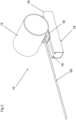
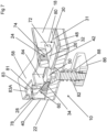
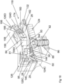
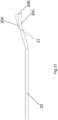
- Figures 1 to 14 of the drawings show a connecting device 10 for connecting an article 12, in the form of a pipe, to a support 14, in the form of a strut.
- the support 14 has return formations 16 extending inwardly thereof.
- the connecting device 10 comprises a clamping arrangement 18 and a flexible elongate member 20.
- the flexible elongate member 20 is in the form of a strap formed of a metallic material.
- the clamping arrangement 18 is disposed on the support 14, and fastened thereto in a manner described below.
- the article 12 is then disposed on the clamping arrangement 18, and attached thereto by means of the flexible elongate member 20.
- the flexible elongate member 20 extends from one end of the clamping arrangement 18, and is wrapped around the article 12.
- the flexible elongate member 20 is inserted back into the opposite end of the clamping arrangement 18 to be clamped therein.
- a tightening element 24 (see Figure 3 ) can then be moved to a tightened position to tighten the flexible elongate member 20 against the article 12
- the clamping arrangement 18 comprises a body 22 having opposite first and second sides 22A, 22B.
- the body 22 defines an internal space 26 extending therethrough.
- the body 22 defines opposite first and second opening arrangements 28, 30 to provide communication between the region external of the body 22 and the internal space 26.
- the first opening arrangement 28 is defined at a first end of the body 22.
- the second opening arrangement 30 is defined at the opposite second end of the body 22.
- the connecting device 10 further includes a carriage 32 (see Figures 6 and 7 ) receivable in the internal space 26.
- the first and second opening arrangements 28, 30 have respective first and second carriage receiving regions 29, 31.
- the carriage 32 is shown specifically in Figure 14 , and carries a clamping element 34 in the form of a wedge captive within a frame 35.
- the clamping element 34 is movable between a clamping position (shown in Figures 8 and 10 ), and a non-clamping position (shown in Figure 13 ). The clamping position and the non-clamping position of the clamping element 34 are described in more detail below.
- the connecting device 10 includes a securing arrangement for securing the carriage 32 to the body 22.
- the securing arrangement comprises two detent formations 36 on the carriage 32 and two cooperating formations 38 on the body 22 (see Figure 4 ), the cooperating formations 38 being configured to cooperate with the detent formations 36 to secure the carriage 32 to the body 22.
- the carriage 32 further includes a reaction member 40 extending between the detent formations 36 at a first end 37 of the carriage 32.
- the detent formations 36 are in the form of outwardly extending hook formations arranged on opposite sides of the carriage 32.
- the cooperating formations 38 are in the form of recesses defined externally in the body 22. The recesses are defined on opposite sides of the body 22 adjacent the first carriage receiving region 29.
- the carriage 32 further includes a substantially planar release portion 42 attached to the reaction member 40 by an urging arrangement in the form of two zig zag springs 44.
- the reaction member 40 can apply a reaction force to the springs 44, so that the springs 44 urge the release portion 42 away from the reaction member 40. As explained below, this movement of the release portion away from the reaction member 40 urges the clamping element 34 to its clamping position.
- the clamping element 34 is provided on the release portion 42.
- the clamping element 34 has a clamping face 46 that is sloped relative to the release portion 42.
- the clamping face 46 is provided with teeth to enhance the grip of the clamping element 34 on the flexible elongate member 20.
- the springs 44 are provided on opposite sides of the clamping element 34, and extend between the release portion 42 and the reaction member 40. The zig zags of the springs 44 are oriented in the plane of the release portion 42.
- the release portion 42 extends to a second end 48 of the carriage 32, and includes an edge region 49 at said second end 48.
- the edge region 49 projects from the body 22 through the second carriage receiving region 31 of the second opening arrangement 30.
- the edge region 49 can be pressed by the user to move the release portion 42 towards the reaction member 40, as indicated by the arrow A in Figures 8 , 10 and 14 . As explained below, this has the effect of moving the clamping element to the non-clamping position (shown in Figure 13 ), by releasing the clamping element 34 from clamping engagement with the flexible elongate member 20.
- the release portion 42 defines a through aperture 50, the purpose of which is described below.
- the body 22 also defines a first access region 78 of the first opening arrangement 28 (see Figure 4 ), and a second access region 80 of the second opening arrangement 30 (see Figure 5 ).
- the first and second access regions 78, 80 are provided to allow access of the flexible elongate member 20 to the internal space 26.
- the first access region 78 communicates with the first carriage receiving region 29.
- the second access region 80 communicates with the second carriage receiving region 31.
- the carriage 32 further includes a ramp formation 52 arranged between the clamping element 34 and the reaction member 40.
- the ramp formation 52 comprises two ramps 54 which extend adjacent the clamping element 34 on opposite sides thereof.
- the body 22 has a V shaped upper holding portion 56 (see Figures 8 to 11 ) for holding the article 12.
- An upper resilient member 58 is adhered to the holding portion 56.
- the upper resilient member 58 is deformable to adopt the shape of the holding portion 56.
- the upper resilient member 58 is resiliently compressible when the flexible elongate member 20 is tightened around the article 12 thereon. This has the effect of preventing over tightening of the flexible elongate member 20 around the article 12. In addition, the upper resilient member 58 provides greater friction than the holding portion 56, thereby reducing longitudinal movement of the article 12.
- the body 22 includes a clamping surface 60 against which the flexible elongate member 20 can be clamped by the clamping element 34. When so clamped, the flexible elongate member 20 is held between the clamping face 46 of the clamping element 34 and the clamping surface 60 of the body 22.
- the body 22 also includes an engaging surface 62 for engaging the clamping element 34 to provide a clamping force on the clamping element 34 when the clamping element 34 clamps the flexible elongate member 20.
- Each of the ramps 54 has a ramped surface 55 to guide the flexible elongate member 20 from the clamping element 34 to the exit region 78. As shown in Figures 8 and 10 , when the clamping element 34 is in the clamping position each of the ramped surfaces 55 of the ramps 54 is disposed further from the clamping surface 60 of the body 22 than the clamping face 46 of the clamping element 34.
- the clamping face 46 of the clamping element 34 is disposed further from the clamping surface 60 of the body 22 than each of the ramped surfaces 55 of the ramp 54. This allows the clamping face 46 to be fully disengaged from the flexible elongate member 20 when the clamping element 34 is in the non-clamping position.
- the clamping surface 60 is a surface defining part of the internal space 26. As can be seen from Figure 8 , the clamping surface 60 is sloped relative to the release portion 42 of the carriage 32. The clamping surface 60 extends at substantially the same angle as the clamping face 46 of the clamping element 34. In use, the flexible elongate member 20 is clamped by the clamping element 34 between the clamping face 46 and the clamping surface 60.
- the tightening element 24 is shown in more detail in Figure 12 , and comprises a bolt insertable into the body 22 at a region over the release portion 42 of the carriage 32.
- the tightening element 24 comprises a head 64 defining a receiving formation in the form of a hexagonal recess 66 for receiving a key with a hexagonal end profile, such as an Allen key. This allows the tightening element 24 to be rotated between a non-tightened position shown in Figures 8 , and 9 , and a tightened position shown in Figure 10 and 11 .
- the head 64 of the tightening element 24 could be provided with a different receiving formation, for example a slot to receive the end of a flat blade screwdriver, or a cross recess to receive the end of a cross head screwdriver, such as a Philips screwdriver.
- the tightening element 24 comprises a shaft 68 having aligned proximal and distal portions 70, 72, the proximal portion 70 being provided at a proximal end of the shaft 68, adjacent the head 64.
- the distal portion 72 is spaced from the proximal portion 70 by a cam member 74.
- the cam member 74 is offset from the aligned proximal and distal portions 70, 72.
- the distal portion 72 extends from the cam member 74 to a distal end of the shaft 68.
- a radially projecting lug 75 is provided on the distal portion 72 at the distal end of the shaft 68.
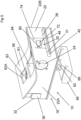
- Figures 9 and 11 show the clamping arrangement 18 from the second side 22B of the body 22.
- the body 22 defines a through bore 69 for receiving the tightening element 24.
- a shoulder portion 77 is provided between the through bore 69 and the second side 22B. The shoulder portion 77 extends in a semi-circle around the through bore 69.
- An elongate recess 79 extends from the shoulder portion 77 to the first side 22A. At each end of the shoulder portion 77, the second side provides notched regions 77A, 77B to hold the lug 75 and thereby hold the tightening element 24 in the non-tightened or tightened positions.
- the tightening element 24 is inserted through the body 22 to a position in which the head 64 is flush with the first side 22A. On insertion, the tightening element is oriented so that the elongate recess 79 receives the lug 75 thereby allowing the tightening element 24 to be received in the through bore 69. When so received, the tightening element 24 is rotated about its main axis to the non-tightened position shown in Figures 8 and 9 . In the non-tightened position, the lug 75 is received in the notched region 77A.
- the user When it is desired tighten the elongate member 20 around the article 12, the user inserts a suitable driver into the hexagonal recess 68, and rotates the tightening element 24 about its main axis from the non-tightened position to the tightened position shown in Figures 10 and 11 . In the tightened position, the lug 75 is received in the notched region 77B.
- the cam member 74 When the tightening element 24 is rotated to the tightened position, the cam member 74 is rotated into tight engagement with the flexible elongate member 20 when the flexible elongate member 20 is wrapped around the article 12 and clamped by the clamping element 34. This pushes the flexible elongate member 20, in the region of the cam member 74, towards the release portion 42. The effect is to pull the flexible elongate member 20 tightly around the article 12.
- the body 22 and the flexible elongate member 20 include corresponding attaching formations to attach an end region 20A (see Figures 24(i) to 29 ) of the flexible elongate member 20 to the body 22.
- the attaching formation of the flexible elongate member 20 is a hole 21 defined in the end region 20A thereof.
- the attaching formation of the body 22 is a projection 81 within the body 22.
- the projection 81 has an apex 81A (see Figure 6 ).
- the body 22 defines an access aperture 83 defined in the V shaped holding portion 56 to allow access to the end region 20A of the flexible elongate member 20.
- a corresponding aperture 83A is defined in the upper resilient member 58. The corresponding aperture 83A is aligned with the aperture 83.
- the access aperture 83 allows the user to install the end region 20A of the flexible elongate member 20 on the projection 81.
- the access aperture 83 communicates with the first access region 78 to allow the flexible elongate member 20 to extend from the projection 81 through the first access region 78.
- the end region 20A of the flexible elongate member 20 may be installed on the projection 81 by the manufacturer. It will be appreciated that other forms of attaching formation could be used.
- the aforesaid end region 20A of the flexible elongate member 20 is fed through the first access region 78 over the projection 81.
- the projection 81 has an inclined surface 85 to engage the end region 20A of the flexible elongate member 20, and allow said end region 20A to slide across the projection 81.
- the user can then manipulate, via the access aperture 83, the end region 20A of the flexible elongate member 20 to arrange the end region 20A over the projection 81, so that the projection 81 is received through the hole 21 in the end region 20A.
- the flexible elongate member 20 extends from the body 22, exiting therefrom via the first access region 78.
- the article 12 is then arranged on the upper resilient member 58 adhered to the V shaped holding portion 56.
- the flexible elongate member 20 is then wrapped around the article 12 and fed back into the body 22 via the second access region 80.
- the flexible elongate member 20 is then fed between the clamping element 34 and the clamping surface 60 of the body 22.
- the spring 44 pulls the clamping element 34 in the direction indicated by the arrow A, thereby clamping the flexible elongate member 20 between the clamping element 34 and the clamping surface 60.
- the tightening element 24 is then rotated from the non-tightened position shown in Figure 8 to the tightened position shown in Figure 9 . This rotation causes the cam member to engage the flexible elongate member 20, and tighten the flexible elongate member 20 against the article 12.
- the connecting device 10 further includes a fastener comprising a countersunk bolt 82 to fasten the connecting device 10 to the support 12.
- the bolt 82 extends through the body 22 via an aperture 84 through the body 22.
- a nut 86 is provided on the bolt 82 so that when the bolt 82 is screwed into the nut 86, the nut 86 is driven into engagement with the return formations 16 of the support 14, thereby fastening the clamping arrangement 18 to the support 14.
- the head of the bolt 82 has a receiving formation in the form of a hexagonal recess to receive a suitable driver in the form of a key with a hexagonal end profile, such as an Allen key.
- the aperture 50 through the release portion 42 of the carriage 32 provides access for the driver to the head of the bolt 82 to allow the bolt 82 to be screwed into the nut 86.
- the bolt 82 is provided with a compression spring 88 extending between the nut 86 and the body 22 to prevent the bolt 82 working itself loose.
- the head of the bolt 82 could be provided with a different receiving formation, for example a slot to receive the end of a flat blade screwdriver, or a cross recess to receive the end of a cross head screwdriver, such as a Phifins screwdriver.
- a connecting device 10 that can attach an article 12, in the form of a pipe, to a support 14, in the form of a strut.
- the connecting device 10 can accommodate various different sizes of pipe in one product so the user does not need to stock several different sized devices.
- the connecting device 10 minimises the number of nuts and bolts used to clamp an article. Only two screws/bolts are used in the connecting device 10, i.e. the bolt 82 to fasten the clamping device 10 to the support 14, and the tightening element 24 to tighten the elongate member 20 around the article 12.
- the projecting edge region of the release portion 42 can be pressed to move the clamping element 34 out of engagement with the elongate member 20, thereby releasing the elongate member 20.
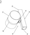
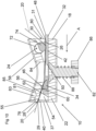
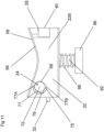
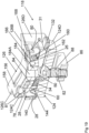
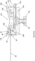
- FIG. 15 to 32 A second embodiment of the connecting device 10 is shown in Figures 15 to 32 , comprising a clamping arrangement 118.
- Figures 15 to 17 show the clamping arrangement 118.
- Figure 17 is an exploded view of the clamping arrangement 118, which comprises a body 122 formed of an inner main part 124 received by an outer cover part 126.
- the outer cover part 126 extends around the inner main part 124 when the outer cover part 126 receives the inner main part 124.
- the clamping arrangement 118 comprises features of the clamping arrangement 18. Those features are designated with the same reference numerals as the corresponding features shown in Figures 1 to 14 .
- the inner main part 124 has the opposite first and second sides 124A, 124B, and front and rear faces 124C, 124D.
- the inner main part 124 defines the internal space 26 and the opposite first and second opening arrangements 28, 30.
- the inner main part 124 also defines the first and second carriage receiving regions 29, 31, and the first and second access regions 78, 80.
- the outer cover part 126 comprises an upper resilient member 158 on an upper V shaped holding portion 156.
- the outer cover part 126 further includes downwardly extending side wall portions 126A, 126B, and front and rear wall portions 126C, 126D.
- the side wall portions 126A, 126B extend over the first and second sides 124A, 124B of the inner main part 124.
- the front and rear wall portions 126C, 126D extend over the front and rear faces 124C, 124D.
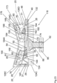
- the front wall portion 126C defines a front opening 178, which aligns with the first access region 78 of the first opening arrangement 28 when the inner main part 124 is received within the outer cover part 126.
- the rear wall portion 126D defines a rear recess 131 and a rear opening 180.
- the rear recess 131 aligns with the second carriage receiving region 31, and the rear opening 180 aligns with the second access region 80 of the second opening arrangement 30.
- the bolt 82 extends through the inner main part 124 to secure the clamping arrangement 118 to the support 14.
- the inner main part 124 defines the aperture 84 to allow the user to reach the bolt 82 with a suitable tool, such as a key with a hexagonal end profile.
- the outer cover part 126 includes a central bore portion 184 defining a through bore 184A.
- the central bore portion 184 extends through the aperture 84, as shown in Figures 18 to 23 and 25 .
- the user can reach the bolt 82 with the tool via the through bore 184A
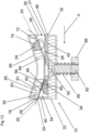
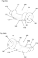
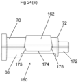
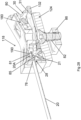
- FIG. 160 there is shown another version of the tightening element, generally designated 160.
- the tightening element 160 is generally the same as the tightening element 24 shown in Figure 12 .
- the tightening element 160 differs from the tightening element 24 in that the radially projecting lug 75 is omitted.
- the tightening element 160 comprises a cam member 162 having a nose portion 164.
- the tightening element 160 further includes a locating member 172 at the distal portion 72.
- the locating member 172 constitutes a journal supported in an aperture in the side wall 124B.
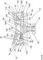
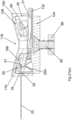
- the inner main part 124 includes an engaging portion 166 having a cam engaging surface 168 and a stop member 170.
- the stop member 170 extends from a lower edge of the cam engaging surface 168.
- the cam engaging surface 168 and the stop member 170 define a cam receiving recess 173 therebetween for receiving the nose portion 164 when the tightening element 160 is in the non-tightened position, shown in Figures 22 and 25 .
- the cam member 162 defines an elongate stop recess 174 opposite the nose portion 164.
- the stop recess 174 receives the stop member 170, thereby stopping the tightening element 160 from being rotated beyond the tightened position shown in Figure 21 .
- the cam member 162 and the inner main part 124 comprise locking formations for locking the tightening element 160 in the non-tightened position.
- the locking formations comprise two indentations 175 defined by the cam member 162.
- the indentations 175 are defined at opposite ends of the elongate stop recess 174 defined by the cam member 162.
- the locking formations may further include two protrusions 176 on the inner main part 124 (see Figures 20 and 21 ).
- the protrusions 176 are arranged on the opposite sides 124A, 124B of the inner main part 124.
- the protrusions 176 are received in the indentations 175 when the tightening element 160 is in its non-tightening position, thereby locking the tightening element 160 in the non-tightening position.
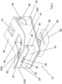
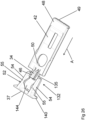
- a further modification comprises a carriage 132 (see Figure 24 ).
- the carriage 132 can be used with either of the clamping arrangements 18 or 118, but is shown in use with the clamping arrangement 118.
- the carriage 132 is similar to the carriage 32 and carries the clamping element 34.
- the carriage 132 is secured to the inner main part 124 of the body 122 by means of the outer cover part 126, as explained below.
- An urging arrangement in the form of a zig zag spring 144, is provided.
- the carriage 132 includes a reaction member 140 extending across the ramps 54.
- the carriage 132 is held in the inner main part 124 by the front wall portion 126C of the outer cover part 126.
- the front wall portion 126C extends over the reaction member 140 in the first carriage receiving region 29 of the first opening arrangement 28.
- the absence of an aperture or recess in the front wall portion 126C aligned with said first carriage receiving recess 29 prevents the carriage 132 being removed from the inner main part 124.
- the front wall portion 126C also provides an abutment for the reaction member 140, thereby allowing the reaction member 140 to apply a reaction force against the spring 144.
- the carriage 132 further includes a release portion 142 on which the clamping element 34 is attached.
- the clamping element 34 is captive within a frame 135.
- the release portion 142 is connected to the reaction member 140 by the spring 144.
- the spring 144 is aligned with the clamping element 34, and is oriented out of the plane of the release portion 142.
- the release portion 42 defines the through aperture 50.
- the inner main part 124 includes the clamping surface 60 and the engaging surface 62 to clamp the flexible elongate member 20.
- the projection 81 is provided within the inner main part 124.
- the projection has a ramped surface 85 along which the end region 20A of the flexible elongate member 20 can slide.
- the inner main part 124 defines the access aperture 83 to allow access to the end region 20A of the flexible elongate member 20 when it is installed on the projection 81.
- a corresponding inner aperture 83B is defined in the outer covering part 126 and through the upper resilient member 158. The inner aperture 83B is aligned with the aperture 83.
- the outer covering part 126 also defines two outer apertures 83C aligned with the aperture 83.
- the outer covering part 126 also has two elongate deflection formations, each deflection formation being in the form of a deflection rib 190 between the inner aperture 83B and the outer apertures 83C.
- Each rib 190 has a lower edge 190A (see Figure 30 ).
- the ribs 190 extend downwardly from the holding portion 156 through the aperture 83 on opposite sides of the projection 81.
- the ribs 190 are arranged such that the lower edge 190A of each rib 190 is substantially level with the apex of the projection 81.
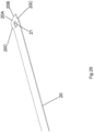
- Figures 27(i) to 27(vi) show the sequence for feeding the end region 20A of the flexible elongate member 20 into the inner main part 124 to receive the projection 81 in the hole 21 in the end region 20A of the flexible elongate member 20.
- the flexible elongate member 20 is lined up with the first access region 78 of the first opening arrangement 28.
- the flexible elongate member 20 is fed into the inner main part 124 via the first access region 78.
- the end edge of the flexible elongate member 20 at the end region 20A engages the inclined surface 85 of the projection 81.
- Figure 27(iii) shows the flexible elongate member 20 fed further into the inner main part 124. This causes the end region 20A to be deformed upwardly along the inclined surface 85. Further movement of the flexible elongate member 20 into the inner main part 124 moves the end edge 20B of the flexible elongate member 20 into engagement with the lower edge 190A of each of the ribs 190 ( Figure 27(iv) ).
- Figure 27(v) is a sectional perspective view of the view shown in Figure 27(v) .
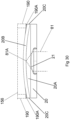
- Figures 29 to 31 show the deformation of the end region 20A of the flexible elongate member 20.
- Figure 30 shows the projection 81 and the ribs 190 schematically in broken lines.
- Figures 29 to 31 show the upward deformation of the end region 20A caused by its movement along the inclined surface 85. They also show the downward deformation of the edge regions 20C around the projection 81, caused by the ribs 190.
- the lower edges 190A of the ribs 190 are substantially level with the apex of the projection 81. Therefore, when the end region 20A is mounted over the projection 81, with the projection 81 received in the hole 21, the end region 20A is prevented from detaching itself from the projection 81 by the ribs 190.
- the inner main part 124 and the outer cover part 126 comprise cooperating affixing formations comprising a plurality of fins 192 at the lower edges of the first and second sides 124A, 124B, and a plurality of corresponding concavities 194 defined in the lower edges of the side wall portions 126A, 126B.
- the affixing formations further include snap fit members 194 on the lower edge of the side wall portions 126A. The snap fit members 194 are arranged to engage the lower edges of the first and second sides 124A, 124B, between the fins 192.
- the fins 192 are received in the concavities 194, and snap fit members engage the under the edges of the first and second sides 124A, 124B, thereby affixing the outer cover part 126 to the inner main part 124.
- the weight of the article 12 clamped thereto, and/or the clamping force applied thereto by the flexible elongate member 20 ensure that the outer cover part 126 to the inner main part 124 are securely affixed to each other.
- the carriage 32 could be used in the clamping arrangement 118 with appropriate changes to the inner main part 124, or the carriage 132 could be used with the clamping arrangement 18 with appropriate changes to the body 22.
- the tightening element 24 could be used with the clamping arrangement 118 with appropriate changes to the inner main part 124, or the tightening element 160 could be used with the clamping arrangement 18 with appropriate changes to the body 22.
Landscapes
- Engineering & Computer Science (AREA)
- General Engineering & Computer Science (AREA)
- Mechanical Engineering (AREA)
- Clamps And Clips (AREA)
Claims (15)
- Verbindungsvorrichtung (10) zum Verbinden eines Gegenstandes (12) mit einem Träger (14), wobei die Verbindungsvorrichtung (10) umfasst:ein flexibles längliches Glied (20); undeine Klemmanordnung (18) zum Festklemmen des flexiblen länglichen Glieds (20) um den Gegenstand (12) herum;wobei die Klemmanordnung (18) einen Körper (22) und ein Klemmelement (34) umfasst, wobei das Klemmelement (34) zwischen Klemm- und Nichtklemmstellungen beweglich ist;wobei in der Klemmstellung das Klemmelement (34) das flexible längliche Glied (20) an den Körper (22) klemmt, wodurch der Gegenstand (12) an der Klemmanordnung (18) befestigt wird, und in der Nichtklemmstellung das flexible längliche Glied (20) durch den Körper (22) hindurch beweglich ist;wobei die Verbindungsvorrichtung (10) ferner einen Schlitten (32) umfasst, um das Klemmelement (34) zu tragen, wobei der Schlitten (32) eine Druck ausübende Anordnung (44) aufweist und der Schlitten (32) ferner ein Reaktionsglied (40) aufweist, um eine Reaktionskraft auf die Druck ausübende Anordnung (44) auszuüben und die Druck ausübende Anordnung (44) in die Lage zu versetzen, das Klemmelement (34) in die Klemmstellung zu drücken;wobei der Körper (22) eine erste Öffnungsanordnung (28) definiert, durch die der Schlitten (32) in den Körper (22) einführbar ist, und der Körper (22) eine zweite Öffnungsanordnung (30) definiert, durch die sich der Schlitten (32) erstreckt, wenn der Schlitten (32) in dem Körper (22) aufgenommen ist;und wobei die zweite Öffnungsanordnung (30) der ersten Öffnungsanordnung (28) gegenüberliegt und der Schlitten (32) einen Freigabeabschnitt (42) zum Bewegen des Klemmelements (34) von der Klemmstellung zu der Nichtklemmstellung aufweist, wobei sich der Freigabeabschnitt (42) durch die zweite Öffnungsanordnung (30) erstreckt, wenn der Schlitten (32) in einem Innenraum des Körpers aufgenommen ist.
- Verbindungsvorrichtung (10) nach Anspruch 1, wobei der Körper (22) ein inneres Hauptteil (124) und ein äußeres Abdeckteil (126) umfasst, wobei das innere Hauptteil (124) eine gegenüberliegende erste und zweite Seite (124A, 124B) und vordere und hintere Flächen (124C, 124D) aufweist und das äußere Abdeckteil (126) ferner sich nach unten erstreckende Seiten-, Vorder- und Rückwandabschnitte (126A, 126B, 126C, 126D) aufweist, wobei sich die Seitenwandabschnitte (126A, 126B) über die erste und zweite Seite (124A, 124B) des inneren Hauptteils (124) erstrecken und sich die Vorder- und Rückwandabschnitte (126C, 126D) über die Vorder- und Rückflächen (124C, 124D) erstrecken.
- Verbindungsvorrichtung (10) nach Anspruch 1 oder 2, wobei der Körper (22) eine Klemmfläche (60) aufweist, gegen die das flexible längliche Glied (20) anklemmbar ist, und das Klemmelement (34) eine Klemmfläche umfasst, um das flexible längliche Glied (20) gegen die Klemmfläche (60) zu klemmen.
- Verbindungsvorrichtung (10) nach einem der vorhergehenden Ansprüche, wobei der Körper (22) und das flexible längliche Glied (20) entsprechende Befestigungsausbildungen aufweisen, um einen Endbereich (20A) des flexiblen länglichen Glieds (20) an dem Körper (22) zu befestigen, wobei eine der entsprechenden Befestigungsausbildungen ein Loch (21) umfasst, das entweder durch das flexible längliche Glied (20) oder den Körper (22) definiert ist, und die andere der Befestigungsausbildungen einen Vorsprung (81) an dem anderen des flexiblen länglichen Glieds (20) oder dem Körper (22) umfasst.
- Verbindungsvorrichtung (10) nach einem der vorhergehenden Ansprüche, umfassend eine Befestigungsanordnung zum Befestigen der Klemmanordnung (18) an dem Träger (14), wobei die Befestigungsanordnung eine durch den Körper (22) definierte Öffnung (84) und ein Befestigungsmittel (82) aufweist, das durch die Öffnung in den Körper (22) einführbar ist.
- Verbindungsvorrichtung (10) nach einem der vorhergehenden Ansprüche, wobei der Schlitten (32) im Wesentlichen flach ist.
- Verbindungsvorrichtung (10) nach einem vorhergehenden Anspruch, wobei ein zweites Ende des Schlittens (32) aus der zweiten Öffnungsanordnung (30) herausragt.
- Verbindungsvorrichtung (10) nach einem vorhergehenden Anspruch, wobei der Schlitten (32) eine Rampenausbildung (52) aufweist, um das flexible längliche Glied (20) durch den Körper (22) hindurch zu führen, wobei sich die Rampenausbildung (52) zwischen dem Klemmelement (34) und dem Reaktionsglied (40) erstreckt.
- Verbindungsvorrichtung (10) nach einem vorhergehenden Anspruch, wobei die Verbindungsvorrichtung (10) ferner ein Festspannelement (24) zum Festspannen des flexiblen länglichen Glieds (20) gegen den Gegenstand (12) aufweist, wobei das Festspannelement (24) beweglich ist, um mit dem flexiblen länglichen Glied (20) in Eingriff zu kommen und das flexible längliche Glied (20) in festen Eingriff mit dem Gegenstand (12) zu drücken.
- Verbindungsvorrichtung (10) nach Anspruch 9, wobei das Festspannelement (24) von dem Körper (22) gehalten wird und das Festspannelement (24) zwischen einer Festspannstellung, in der das Festspannelement (24) gegen das flexible längliche Glied (20) festgespannt ist, und einer nicht festgespannten Stellung, in der das Festspannelement (24) nicht gegen das flexible längliche Glied (20) festgespannt ist, drehbar ist.
- Verbindungsvorrichtung (10) nach Anspruch 10, wobei das Festspannelement (24) eine Hauptachse aufweist, um die herum sich das Festspannelement (24) dreht, wobei das Festspannelement (24) eine Welle (68) aufweist, die mit der Hauptachse ausgerichtet ist.
- Verbindungsvorrichtung (10) nach Anspruch 11, wobei der Welle (68) einen proximalen Abschnitt (70) und einen distalen Abschnitt (72) umfasst und das Festspannelement (24) ferner ein Nockenglied (74) zum Eingriff mit dem flexiblen länglichen Glied (20) umfasst, wobei das Nockenglied (74) von der Hauptachse versetzt ist.
- Verbindungsvorrichtung (10) nach Anspruch 12, wobei der Körper (22) einen Eingriffsabschnitt (166) mit einer Nockeneingriffsfläche (168) zum Eingriff mit dem Nockenglied (74) aufweist, und wobei der Eingriffsabschnitt (166) ferner ein Anschlagglied (170) aufweist, das sich von der Nockeneingriffsfläche (168) erstreckt, wobei das Anschlagglied (170) mit dem Nockenglied (74) in Eingriff steht, wenn sich das Nockenglied (74) in der nicht festgespannten Stellung befindet.
- Verbindungsvorrichtung (10) nach einem der Ansprüche 12 bis 13, wobei das Nockenglied (162) und der Körper (122) Verriegelungsausbildungen zum Verriegeln des Festspannelementes (160) in der nicht festgespannten Stellung umfassen, wobei die Verriegelungsausbildungen eine Vertiefung (175) auf entweder dem Festspannelement (160) oder dem Körper (122) und einen Vorsprung (176) auf dem anderen des Festspannelements (160) und des Körpers (122) umfassen.
- Verbindungsvorrichtung nach Anspruch 14, wobei die Vertiefung (175) durch das Nockenglied (162) definiert ist und der Vorsprung (176) sich auf dem Körper (122) befindet.
Applications Claiming Priority (4)
| Application Number | Priority Date | Filing Date | Title |
|---|---|---|---|
| GBGB1906663.8A GB201906663D0 (en) | 2019-05-11 | 2019-05-11 | Connecting device |
| GB201915523A GB201915523D0 (en) | 2019-10-25 | 2019-10-25 | Connecting device |
| GB2006024.0A GB2585748B (en) | 2019-05-11 | 2020-04-24 | Connecting device |
| PCT/IB2020/054197 WO2020229937A1 (en) | 2019-05-11 | 2020-05-04 | Connecting device |
Publications (3)
| Publication Number | Publication Date |
|---|---|
| EP3969795A1 EP3969795A1 (de) | 2022-03-23 |
| EP3969795C0 EP3969795C0 (de) | 2024-07-17 |
| EP3969795B1 true EP3969795B1 (de) | 2024-07-17 |
Family
ID=71080044
Family Applications (1)
| Application Number | Title | Priority Date | Filing Date |
|---|---|---|---|
| EP20731550.8A Active EP3969795B1 (de) | 2019-05-11 | 2020-05-04 | Anschlussvorrichtung |
Country Status (12)
| Country | Link |
|---|---|
| US (1) | US12286993B2 (de) |
| EP (1) | EP3969795B1 (de) |
| JP (1) | JP7543312B2 (de) |
| CN (1) | CN113811710B (de) |
| AU (1) | AU2020273644A1 (de) |
| BR (1) | BR112021019525A2 (de) |
| CA (1) | CA3132018A1 (de) |
| CL (1) | CL2021002979A1 (de) |
| GB (2) | GB2615902B (de) |
| MX (1) | MX2021013740A (de) |
| WO (1) | WO2020229937A1 (de) |
| ZA (1) | ZA202107528B (de) |
Families Citing this family (2)
| Publication number | Priority date | Publication date | Assignee | Title |
|---|---|---|---|---|
| GB2615902B (en) * | 2019-05-11 | 2024-01-03 | Gripple Ltd | Connecting device |
| AU2021221793A1 (en) * | 2021-04-22 | 2022-11-10 | Woodform Architectural Pty Ltd t/a Sculptform | A Batten Fixing Clip And A Method Of Fixing The Clip |
Family Cites Families (82)
| Publication number | Priority date | Publication date | Assignee | Title |
|---|---|---|---|---|
| US2345279A (en) * | 1943-02-09 | 1944-03-28 | Adel Prec Products Corp | Wire supporting clip |
| US2426708A (en) * | 1944-06-12 | 1947-09-02 | Adel Prec Products Corp | Adjustable wire or conduit clip |
| US3532311A (en) * | 1968-05-01 | 1970-10-06 | Spring Steel Fasteners Inc | Spring clip hanger for conduit and the like |
| GB1227568A (de) * | 1968-05-02 | 1971-04-07 | ||
| JPS479120Y1 (de) * | 1969-04-05 | 1972-04-06 | ||
| US3698042A (en) * | 1971-01-25 | 1972-10-17 | Sidney H Hirschhorn | Rope clamps |
| GB1419760A (en) * | 1971-09-23 | 1975-12-31 | Piddington R W | Releasable locking means for controlling movement between relatively movable members |
| GB2075588B (en) * | 1980-05-10 | 1984-05-02 | Marston Albert & Co Ltd | Locks |
| US4458385A (en) * | 1982-05-20 | 1984-07-10 | Hollingsead International, Inc. | Avionic clamp having separate strap and locking member |
| US4510650A (en) * | 1983-12-28 | 1985-04-16 | Hollingsead International, Inc. | Cable clamp assembly |
| US4813105A (en) * | 1984-02-06 | 1989-03-21 | Hollingsead International, Inc. | Cable clamp |
| GB8421027D0 (en) * | 1984-08-17 | 1984-09-19 | Conoco Inc | Clamps for pipelines |
| US4665590A (en) * | 1986-04-11 | 1987-05-19 | Illinois Tool Works Inc. | Cord retainer assembly |
| JPH0619212B2 (ja) | 1986-07-08 | 1994-03-16 | いすゞ自動車株式会社 | 燃焼器 |
| JPH066252Y2 (ja) * | 1986-07-19 | 1994-02-16 | 加藤発条株式会社 | コルゲートチューブ固定用突堤を備えたバンドクリップ |
| JPH01501919A (ja) | 1986-09-10 | 1989-07-06 | ナショナル・モールディング・コーポレーション | コードファスナー |
| JPS63272302A (ja) * | 1987-04-30 | 1988-11-09 | モリト株式会社 | 紐の調節固定具及びその製造方法 |
| US4768741A (en) * | 1987-04-30 | 1988-09-06 | Logsdon Duane D | Pipe hangers |
| US4878270A (en) * | 1989-05-09 | 1989-11-07 | Westerkamp Myron M | Rope tie-down apparatus |
| JP2534800Y2 (ja) * | 1990-04-27 | 1997-05-07 | 大和化成工業 株式会社 | ベルトクランプ |
| US5042114A (en) * | 1991-01-04 | 1991-08-27 | Parrish Charles E | Adjustable clamp with handle |
| US5402557A (en) | 1993-05-03 | 1995-04-04 | Dalen; Thomas M. | Dynamic self-adjusting tie-down device for transportable items |
| US5291637A (en) * | 1993-06-01 | 1994-03-08 | Jonathan Meyers | Vibration resistant metallic tie |
| US5423644A (en) * | 1993-08-05 | 1995-06-13 | R.C. First Enterprises, Inc. | Cargo tie-down having mechanical advantage |
| CA2186814A1 (en) * | 1996-03-01 | 1997-09-02 | Bell Sportrack, Division Of Bell Sports Canada Inc. | Universal load-carrying utility rack for vehicles |
| US5671505A (en) * | 1996-05-15 | 1997-09-30 | National Molding Corp. | Preloadable cord lock requiring less force to preload and to actuate |
| US5775653A (en) * | 1996-05-30 | 1998-07-07 | Chrysler Corporation | Clamp device for attaching and positively orienting a vehicular component to a tubular member |
| US5779259A (en) * | 1996-06-14 | 1998-07-14 | Lin; Jack | Toe-strap of a ski boot binding |
| US5745959A (en) * | 1997-01-07 | 1998-05-05 | The Burton Corporation | Ratchet-type buckle |
| US6126122A (en) * | 1997-11-06 | 2000-10-03 | Sioux Chief Manufacturing Co., Inc. | Double ratchet arm pipe clamp |
| IL122449A (en) * | 1997-12-04 | 2000-08-13 | Menachem Izhack | Fastening device for installing gas or liquid conducting pipes |
| US6185303B1 (en) * | 1997-12-23 | 2001-02-06 | Francis R. Losey | Enclosure mounting bracket |
| US5894639A (en) * | 1998-03-19 | 1999-04-20 | Robert O. Boden | Cord lock apparatus |
| US6347817B1 (en) * | 2000-03-07 | 2002-02-19 | Yeh-Chien Chou | Locking device for use in a cargo support to lock a retractable tube |
| US6374464B1 (en) * | 2000-07-25 | 2002-04-23 | Chin-Kuo Lai | Buckle with fine adjustment means |
| US6457214B1 (en) * | 2000-10-13 | 2002-10-01 | Robert O. Boden | Tamper-resistant cord lock apparatus |
| US6868585B2 (en) * | 2001-07-26 | 2005-03-22 | Indiana Mills & Manufacturing, Inc. | Web adjuster device |
| US6684667B2 (en) * | 2001-08-10 | 2004-02-03 | Zelco Industries, Inc. | Luggage strap with ratchet and lock |
| JP2003134648A (ja) * | 2001-10-16 | 2003-05-09 | Yazaki Corp | クランプおよびその取付構造 |
| US6898825B1 (en) * | 2003-08-18 | 2005-05-31 | Scott R. Charest | Hose clamp |
| JP4257288B2 (ja) | 2004-12-16 | 2009-04-22 | ポップリベット・ファスナー株式会社 | 長尺部材用クランプ |
| SE530939C2 (sv) * | 2007-03-23 | 2008-10-28 | Tom Kuehne | Buntband |
| GB2464149B8 (en) * | 2008-10-07 | 2017-11-22 | Colebrook Bosson & Saunders (Products) Ltd | An assembly to attach a display device to a display device support |
| GB0911711D0 (en) * | 2009-07-06 | 2009-08-19 | Abdul Yaragi | Fastening device |
| GB2473320B (en) * | 2009-09-08 | 2011-09-07 | Gripple Ltd | Securing apparatus |
| US20110277700A1 (en) * | 2010-05-13 | 2011-11-17 | Pawz Dog Boots, LLC | Locking pet lead system comprising a leash and collar to prevent the theft of pets |
| US20120017400A1 (en) * | 2010-07-21 | 2012-01-26 | Tim James Ussher | Cord clamping device |
| US20120085609A1 (en) * | 2010-10-11 | 2012-04-12 | Go-Go Babyz Corp. | Strap System and Method for Securing a Child Safety Seat to Wheeled Luggage |
| EP3088768A3 (de) * | 2010-10-11 | 2017-02-15 | Ideal Industries, Inc. | Bindervorrichtung zum schnüren von kabeln |
| US8938862B2 (en) * | 2011-04-26 | 2015-01-27 | Andre' Grasso | Tie-down strap with braking system and method |
| US8434979B1 (en) * | 2011-05-09 | 2013-05-07 | David Genge | Portable gear ratchet for tie-downs |
| US8955198B2 (en) * | 2011-08-28 | 2015-02-17 | Jeffrey D. Carnevali | Releasable strap mount |
| US20140150222A1 (en) * | 2012-05-15 | 2014-06-05 | Yakima Innovation Development Corporation | Strap for securing cargo on a vehicle |
| US9199571B2 (en) * | 2012-07-03 | 2015-12-01 | Cequent Consumer Products, Inc. | Adjustable flexible cargo strap |
| US9010824B2 (en) * | 2012-11-14 | 2015-04-21 | John W. Hayes | Cargo strap with handle |
| US8522402B1 (en) * | 2012-12-11 | 2013-09-03 | James D. Spooler | Cargo strap collector |
| DE102013001125B3 (de) * | 2013-01-23 | 2014-07-10 | Norma Germany Gmbh | Spannvorrichtung |
| US9185948B2 (en) * | 2013-01-28 | 2015-11-17 | Jezekiel Ben-Arie | Buckle-lace: lace fastening device |
| US8763211B1 (en) * | 2013-03-04 | 2014-07-01 | Cheng-Che Yu | Binding belt-based rod member clamping device |
| CN203237579U (zh) * | 2013-03-05 | 2013-10-16 | 上海易扣精密件制造有限公司 | 圆孔固定型可释放捆扎带 |
| FR3003622B1 (fr) * | 2013-03-21 | 2015-10-02 | Technip France | Dispositif sous-marin d'appui et methode d'installation pour initier le flambement lateral d'une conduite rigide |
| US9155359B1 (en) * | 2013-09-16 | 2015-10-13 | Dennis Morgan Bailey | Ratchet buckle with locking mechanism |
| US9068674B1 (en) * | 2013-12-17 | 2015-06-30 | Peter G. Mangone, Jr. | Cable, conduit, pipe and wire affixing clip |
| CA2889880C (en) * | 2014-05-02 | 2022-05-31 | Cooper Technologies Company | Conduit clamp for strut channel |
| DE102014106227A1 (de) * | 2014-05-05 | 2015-11-05 | ABUS August Bremicker Söhne KG | Kabelverriegelungssystem |
| CN106415101B (zh) * | 2014-06-20 | 2020-09-25 | 莱克产品有限公司 | 多级配合夹具 |
| US11359695B2 (en) * | 2016-04-11 | 2022-06-14 | ComScope Connectivity Belgium BVBA | Universal cable attachment |
| CA3006212A1 (en) * | 2017-05-26 | 2018-11-26 | Buckingham Manufacturing Company, Inc. | Length adjusting devices and method of using the same |
| CN107288449B (zh) * | 2017-08-01 | 2022-08-02 | 宁波市攸曼儿童防护用品有限公司 | 一种扎带挂锁 |
| US10070701B1 (en) * | 2017-11-06 | 2018-09-11 | Bo Cai Enterprise Co., Ltd. | Buckle device |
| US10441035B1 (en) * | 2018-06-08 | 2019-10-15 | Duraflex Hong Kong Limited | Cord lock |
| US10801581B2 (en) * | 2018-08-01 | 2020-10-13 | Frank Flynt Ranum | Cord coupling system |
| US11833646B2 (en) * | 2018-09-14 | 2023-12-05 | Illinois Tool Works Inc. | Mounting system for box profile |
| US10718364B2 (en) * | 2018-10-12 | 2020-07-21 | Geromie Joel Isom | Accessory clamp for elongated structural members |
| US20200248781A1 (en) * | 2019-02-01 | 2020-08-06 | Craig W. Patterson | Cinching device |
| DE202020102347U1 (de) * | 2019-05-01 | 2020-07-24 | Ti-An Chih | Ein sofortiges und präzises Verriegeln und Lösen eines Seils ermöglichende Vorrichtung |
| GB2615902B (en) * | 2019-05-11 | 2024-01-03 | Gripple Ltd | Connecting device |
| CN114867378B (zh) * | 2019-10-03 | 2024-09-17 | 耐克创新有限合伙公司 | 动态系带系统 |
| US11339852B1 (en) * | 2021-04-27 | 2022-05-24 | Daniel Austin | Adjustable hook with strap |
| US11677227B2 (en) * | 2021-09-10 | 2023-06-13 | Panduit Corp. | Dual tongue strap cleat bracket |
| US12031610B2 (en) * | 2021-12-22 | 2024-07-09 | Brady Worldwide, Inc. | Clamping cable lockout |
| JP2024017658A (ja) * | 2022-07-28 | 2024-02-08 | 大和化成工業株式会社 | ベルトクランプ |
-
2020
- 2020-04-24 GB GB2304406.8A patent/GB2615902B/en active Active
- 2020-04-24 GB GB2006024.0A patent/GB2585748B/en active Active
- 2020-05-04 US US17/599,451 patent/US12286993B2/en active Active
- 2020-05-04 JP JP2021567855A patent/JP7543312B2/ja active Active
- 2020-05-04 CN CN202080034518.0A patent/CN113811710B/zh active Active
- 2020-05-04 AU AU2020273644A patent/AU2020273644A1/en not_active Abandoned
- 2020-05-04 EP EP20731550.8A patent/EP3969795B1/de active Active
- 2020-05-04 BR BR112021019525A patent/BR112021019525A2/pt not_active Application Discontinuation
- 2020-05-04 MX MX2021013740A patent/MX2021013740A/es unknown
- 2020-05-04 CA CA3132018A patent/CA3132018A1/en active Pending
- 2020-05-04 WO PCT/IB2020/054197 patent/WO2020229937A1/en not_active Ceased
-
2021
- 2021-10-06 ZA ZA2021/07528A patent/ZA202107528B/en unknown
- 2021-11-10 CL CL2021002979A patent/CL2021002979A1/es unknown
Also Published As
| Publication number | Publication date |
|---|---|
| JP7543312B2 (ja) | 2024-09-02 |
| CN113811710B (zh) | 2025-07-11 |
| GB2585748B (en) | 2023-09-06 |
| GB202304406D0 (en) | 2023-05-10 |
| CN113811710A (zh) | 2021-12-17 |
| GB2615902A (en) | 2023-08-23 |
| AU2020273644A1 (en) | 2021-10-28 |
| EP3969795A1 (de) | 2022-03-23 |
| CA3132018A1 (en) | 2020-11-19 |
| GB2585748A (en) | 2021-01-20 |
| BR112021019525A2 (pt) | 2021-12-07 |
| JP2022531971A (ja) | 2022-07-12 |
| EP3969795C0 (de) | 2024-07-17 |
| ZA202107528B (en) | 2025-01-29 |
| US12286993B2 (en) | 2025-04-29 |
| GB202006024D0 (en) | 2020-06-10 |
| GB2615902B (en) | 2024-01-03 |
| MX2021013740A (es) | 2021-12-10 |
| WO2020229937A1 (en) | 2020-11-19 |
| CL2021002979A1 (es) | 2022-06-24 |
| US20220196057A1 (en) | 2022-06-23 |
Similar Documents
| Publication | Publication Date | Title |
|---|---|---|
| EP1584521B1 (de) | System zur Montage eines Airbag-Moduls | |
| US7093518B2 (en) | Tool for tensioning, slackening and opening spring-clip elements | |
| CA2096904C (en) | Channel nut fastener | |
| US6622976B1 (en) | Cable hanger for installing cables on transmitting tower | |
| USRE45825E1 (en) | Fast beam clamp | |
| EP3969795B1 (de) | Anschlussvorrichtung | |
| AU2020201302B2 (en) | Load carrier foot | |
| US20160223010A1 (en) | Speed nut | |
| US11560916B2 (en) | Bolt attachment | |
| WO2020264433A1 (en) | Clamp assembly | |
| CZ20003016A3 (cs) | Upínka s upínacím uzávěrem | |
| US7076844B2 (en) | Open sided cam lock for ropes | |
| EP3106351A1 (de) | Lastträgerfuss | |
| JP2006234166A (ja) | リテーナ組立て品 | |
| US20090238659A1 (en) | Fastening Device Having Fastening Element | |
| US4343451A (en) | Sensor retaining system | |
| CN101688338B (zh) | 具有受到过载保护的紧固夹持器的纱线输送设备 | |
| CN107645996B (zh) | 用于固定呈条状的添置件的组件 | |
| CN210926285U (zh) | 一种固定套和天线 | |
| WO2025019673A1 (en) | Plugs, clips, and fasteners | |
| EP2609825A1 (de) | Verschlussklemme und Verschlussanordnung | |
| CA2552448A1 (en) | Improvements in relation to blind bolting |
Legal Events
| Date | Code | Title | Description |
|---|---|---|---|
| STAA | Information on the status of an ep patent application or granted ep patent |
Free format text: STATUS: UNKNOWN |
|
| STAA | Information on the status of an ep patent application or granted ep patent |
Free format text: STATUS: THE INTERNATIONAL PUBLICATION HAS BEEN MADE |
|
| PUAI | Public reference made under article 153(3) epc to a published international application that has entered the european phase |
Free format text: ORIGINAL CODE: 0009012 |
|
| STAA | Information on the status of an ep patent application or granted ep patent |
Free format text: STATUS: REQUEST FOR EXAMINATION WAS MADE |
|
| 17P | Request for examination filed |
Effective date: 20211117 |
|
| AK | Designated contracting states |
Kind code of ref document: A1 Designated state(s): AL AT BE BG CH CY CZ DE DK EE ES FI FR GB GR HR HU IE IS IT LI LT LU LV MC MK MT NL NO PL PT RO RS SE SI SK SM TR |
|
| DAV | Request for validation of the european patent (deleted) | ||
| DAX | Request for extension of the european patent (deleted) | ||
| STAA | Information on the status of an ep patent application or granted ep patent |
Free format text: STATUS: EXAMINATION IS IN PROGRESS |
|
| 17Q | First examination report despatched |
Effective date: 20230504 |
|
| GRAP | Despatch of communication of intention to grant a patent |
Free format text: ORIGINAL CODE: EPIDOSNIGR1 |
|
| STAA | Information on the status of an ep patent application or granted ep patent |
Free format text: STATUS: GRANT OF PATENT IS INTENDED |
|
| RIC1 | Information provided on ipc code assigned before grant |
Ipc: F16B 21/02 20060101ALN20240418BHEP Ipc: F16B 2/08 20060101ALN20240418BHEP Ipc: F16M 11/04 20060101ALI20240418BHEP Ipc: F16G 11/10 20060101ALI20240418BHEP Ipc: F16B 37/04 20060101ALI20240418BHEP Ipc: F16B 19/02 20060101ALI20240418BHEP Ipc: F16L 3/24 20060101ALI20240418BHEP Ipc: F16L 3/10 20060101ALI20240418BHEP Ipc: F16L 3/137 20060101AFI20240418BHEP |
|
| RIC1 | Information provided on ipc code assigned before grant |
Ipc: F16B 21/02 20060101ALN20240426BHEP Ipc: F16B 2/08 20060101ALN20240426BHEP Ipc: F16M 11/04 20060101ALI20240426BHEP Ipc: F16G 11/10 20060101ALI20240426BHEP Ipc: F16B 37/04 20060101ALI20240426BHEP Ipc: F16B 19/02 20060101ALI20240426BHEP Ipc: F16L 3/24 20060101ALI20240426BHEP Ipc: F16L 3/10 20060101ALI20240426BHEP Ipc: F16L 3/137 20060101AFI20240426BHEP |
|
| INTG | Intention to grant announced |
Effective date: 20240508 |
|
| GRAS | Grant fee paid |
Free format text: ORIGINAL CODE: EPIDOSNIGR3 |
|
| GRAA | (expected) grant |
Free format text: ORIGINAL CODE: 0009210 |
|
| STAA | Information on the status of an ep patent application or granted ep patent |
Free format text: STATUS: THE PATENT HAS BEEN GRANTED |
|
| AK | Designated contracting states |
Kind code of ref document: B1 Designated state(s): AL AT BE BG CH CY CZ DE DK EE ES FI FR GB GR HR HU IE IS IT LI LT LU LV MC MK MT NL NO PL PT RO RS SE SI SK SM TR |
|
| REG | Reference to a national code |
Ref country code: CH Ref legal event code: EP |
|
| REG | Reference to a national code |
Ref country code: DE Ref legal event code: R096 Ref document number: 602020034115 Country of ref document: DE |
|
| REG | Reference to a national code |
Ref country code: IE Ref legal event code: FG4D |
|
| U01 | Request for unitary effect filed |
Effective date: 20240731 |
|
| U07 | Unitary effect registered |
Designated state(s): AT BE BG DE DK EE FI FR IT LT LU LV MT NL PT SE SI Effective date: 20240819 |
|
| PG25 | Lapsed in a contracting state [announced via postgrant information from national office to epo] |
Ref country code: NO Free format text: LAPSE BECAUSE OF FAILURE TO SUBMIT A TRANSLATION OF THE DESCRIPTION OR TO PAY THE FEE WITHIN THE PRESCRIBED TIME-LIMIT Effective date: 20241017 |
|
| PG25 | Lapsed in a contracting state [announced via postgrant information from national office to epo] |
Ref country code: PL Free format text: LAPSE BECAUSE OF FAILURE TO SUBMIT A TRANSLATION OF THE DESCRIPTION OR TO PAY THE FEE WITHIN THE PRESCRIBED TIME-LIMIT Effective date: 20240717 Ref country code: GR Free format text: LAPSE BECAUSE OF FAILURE TO SUBMIT A TRANSLATION OF THE DESCRIPTION OR TO PAY THE FEE WITHIN THE PRESCRIBED TIME-LIMIT Effective date: 20241018 |
|
| PG25 | Lapsed in a contracting state [announced via postgrant information from national office to epo] |
Ref country code: IS Free format text: LAPSE BECAUSE OF FAILURE TO SUBMIT A TRANSLATION OF THE DESCRIPTION OR TO PAY THE FEE WITHIN THE PRESCRIBED TIME-LIMIT Effective date: 20241117 |
|
| PG25 | Lapsed in a contracting state [announced via postgrant information from national office to epo] |
Ref country code: HR Free format text: LAPSE BECAUSE OF FAILURE TO SUBMIT A TRANSLATION OF THE DESCRIPTION OR TO PAY THE FEE WITHIN THE PRESCRIBED TIME-LIMIT Effective date: 20240717 |
|
| PG25 | Lapsed in a contracting state [announced via postgrant information from national office to epo] |
Ref country code: ES Free format text: LAPSE BECAUSE OF FAILURE TO SUBMIT A TRANSLATION OF THE DESCRIPTION OR TO PAY THE FEE WITHIN THE PRESCRIBED TIME-LIMIT Effective date: 20240717 Ref country code: RS Free format text: LAPSE BECAUSE OF FAILURE TO SUBMIT A TRANSLATION OF THE DESCRIPTION OR TO PAY THE FEE WITHIN THE PRESCRIBED TIME-LIMIT Effective date: 20241017 |
|
| PG25 | Lapsed in a contracting state [announced via postgrant information from national office to epo] |
Ref country code: RS Free format text: LAPSE BECAUSE OF FAILURE TO SUBMIT A TRANSLATION OF THE DESCRIPTION OR TO PAY THE FEE WITHIN THE PRESCRIBED TIME-LIMIT Effective date: 20241017 Ref country code: PL Free format text: LAPSE BECAUSE OF FAILURE TO SUBMIT A TRANSLATION OF THE DESCRIPTION OR TO PAY THE FEE WITHIN THE PRESCRIBED TIME-LIMIT Effective date: 20240717 Ref country code: NO Free format text: LAPSE BECAUSE OF FAILURE TO SUBMIT A TRANSLATION OF THE DESCRIPTION OR TO PAY THE FEE WITHIN THE PRESCRIBED TIME-LIMIT Effective date: 20241017 Ref country code: IS Free format text: LAPSE BECAUSE OF FAILURE TO SUBMIT A TRANSLATION OF THE DESCRIPTION OR TO PAY THE FEE WITHIN THE PRESCRIBED TIME-LIMIT Effective date: 20241117 Ref country code: HR Free format text: LAPSE BECAUSE OF FAILURE TO SUBMIT A TRANSLATION OF THE DESCRIPTION OR TO PAY THE FEE WITHIN THE PRESCRIBED TIME-LIMIT Effective date: 20240717 Ref country code: GR Free format text: LAPSE BECAUSE OF FAILURE TO SUBMIT A TRANSLATION OF THE DESCRIPTION OR TO PAY THE FEE WITHIN THE PRESCRIBED TIME-LIMIT Effective date: 20241018 Ref country code: ES Free format text: LAPSE BECAUSE OF FAILURE TO SUBMIT A TRANSLATION OF THE DESCRIPTION OR TO PAY THE FEE WITHIN THE PRESCRIBED TIME-LIMIT Effective date: 20240717 |
|
| PG25 | Lapsed in a contracting state [announced via postgrant information from national office to epo] |
Ref country code: SM Free format text: LAPSE BECAUSE OF FAILURE TO SUBMIT A TRANSLATION OF THE DESCRIPTION OR TO PAY THE FEE WITHIN THE PRESCRIBED TIME-LIMIT Effective date: 20240717 |
|
| PG25 | Lapsed in a contracting state [announced via postgrant information from national office to epo] |
Ref country code: CZ Free format text: LAPSE BECAUSE OF FAILURE TO SUBMIT A TRANSLATION OF THE DESCRIPTION OR TO PAY THE FEE WITHIN THE PRESCRIBED TIME-LIMIT Effective date: 20240717 |
|
| PG25 | Lapsed in a contracting state [announced via postgrant information from national office to epo] |
Ref country code: SK Free format text: LAPSE BECAUSE OF FAILURE TO SUBMIT A TRANSLATION OF THE DESCRIPTION OR TO PAY THE FEE WITHIN THE PRESCRIBED TIME-LIMIT Effective date: 20240717 |
|
| PLBE | No opposition filed within time limit |
Free format text: ORIGINAL CODE: 0009261 |
|
| STAA | Information on the status of an ep patent application or granted ep patent |
Free format text: STATUS: NO OPPOSITION FILED WITHIN TIME LIMIT |
|
| 26N | No opposition filed |
Effective date: 20250422 |