EP3969286B1 - Belüfteter druckkopf - Google Patents
Belüfteter druckkopf Download PDFInfo
- Publication number
- EP3969286B1 EP3969286B1 EP20733310.5A EP20733310A EP3969286B1 EP 3969286 B1 EP3969286 B1 EP 3969286B1 EP 20733310 A EP20733310 A EP 20733310A EP 3969286 B1 EP3969286 B1 EP 3969286B1
- Authority
- EP
- European Patent Office
- Prior art keywords
- print head
- openings
- gas
- nozzle
- nozzles
- Prior art date
- Legal status (The legal status is an assumption and is not a legal conclusion. Google has not performed a legal analysis and makes no representation as to the accuracy of the status listed.)
- Active
Links
Images
Classifications
-
- B—PERFORMING OPERATIONS; TRANSPORTING
- B41—PRINTING; LINING MACHINES; TYPEWRITERS; STAMPS
- B41J—TYPEWRITERS; SELECTIVE PRINTING MECHANISMS, i.e. MECHANISMS PRINTING OTHERWISE THAN FROM A FORME; CORRECTION OF TYPOGRAPHICAL ERRORS
- B41J2/00—Typewriters or selective printing mechanisms characterised by the printing or marking process for which they are designed
- B41J2/005—Typewriters or selective printing mechanisms characterised by the printing or marking process for which they are designed characterised by bringing liquid or particles selectively into contact with a printing material
- B41J2/01—Ink jet
- B41J2/015—Ink jet characterised by the jet generation process
- B41J2/04—Ink jet characterised by the jet generation process generating single droplets or particles on demand
- B41J2/06—Ink jet characterised by the jet generation process generating single droplets or particles on demand by electric or magnetic field
-
- B—PERFORMING OPERATIONS; TRANSPORTING
- B41—PRINTING; LINING MACHINES; TYPEWRITERS; STAMPS
- B41J—TYPEWRITERS; SELECTIVE PRINTING MECHANISMS, i.e. MECHANISMS PRINTING OTHERWISE THAN FROM A FORME; CORRECTION OF TYPOGRAPHICAL ERRORS
- B41J2/00—Typewriters or selective printing mechanisms characterised by the printing or marking process for which they are designed
- B41J2/005—Typewriters or selective printing mechanisms characterised by the printing or marking process for which they are designed characterised by bringing liquid or particles selectively into contact with a printing material
- B41J2/01—Ink jet
- B41J2/135—Nozzles
- B41J2/14—Structure thereof only for on-demand ink jet heads
- B41J2/1433—Structure of nozzle plates
-
- B—PERFORMING OPERATIONS; TRANSPORTING
- B41—PRINTING; LINING MACHINES; TYPEWRITERS; STAMPS
- B41J—TYPEWRITERS; SELECTIVE PRINTING MECHANISMS, i.e. MECHANISMS PRINTING OTHERWISE THAN FROM A FORME; CORRECTION OF TYPOGRAPHICAL ERRORS
- B41J2202/00—Embodiments of or processes related to ink-jet or thermal heads
- B41J2202/01—Embodiments of or processes related to ink-jet heads
- B41J2202/02—Air-assisted ejection
Definitions
- the invention relates to a print head for depositing ink on a substrate.
- the invention also relates to a printing system with such a print head and to a method for operating such a print head.
- US 2018/0009223 describes an electrohydrodynamic print head having a nozzle layer comprising a plurality of nozzles. It is based on a structure where the nozzles are arranged on one side and feed ducts extend through a feed layer on the other side.
- US 2019/0292934 describes a print head having a nozzle layer (24) with a plurality of nozzles and a plurality of ventilation openings extending through the nozzle layer.
- Nozzle electrodes are used to accelerate ink away from the nozzles and onto a target.
- JP 2011005422 describes a piezoelectric print head having ventilation openings.
- the problem to be solved by the present invention is to provide a print head of the type mentioned above that has improved printing quality.
- the print head comprises a nozzle layer.
- This nozzle layer in its turn comprises at least the following parts:
- the ventilation openings allow to feed a gas to the region between the printing head and the target and/or to convey gas away from said region. Hence, it becomes possible to control or at least modify the composition of the gas in the space where printing takes place, which provides a wealth of options for controlling the printing process. Some of these options are described below.
- the print head comprises a core region-with activatable nozzles and ventilation openings.
- the print head further comprises
- This edge region allows to generate a more homogeneous flow pattern and therefore a better printing result.
- the ventilation openings advantageously comprise at least two types of openings: A first type is designed as suction openings for feeding gas away from the region adjacent to the nozzles. The second type is designed as blow openings for feeding gas towards said region.
- the invention provides improved printing quality while suffering from less clogging problems.
- the use of many nozzles on a flat multi-nozzle print head can result in the accumulation of evaporated liquid in the region between the print head and a target that is printed on.
- This problem is particularly pronounced for electrohydrodynamic multi-nozzle print heads like that disclosed in US 2018/009223 where printing resolutions can be in the sub-10um, potentially even in the sub-1 um resolution regime.
- print heads potentially allow the use of millions of nozzles arranged in large nozzle arrays, for example as disclosed in WO 2016/169956 .
- nozzles may be arranged in much larger numbers and in rectangular arrays that are largely of similar size along both main array axes.
- ink-jet print heads are normally built such that nozzles are arranged within narrow rectangular or skewed rectangular areas, wherein a fast movement is exercised essentially in direction of the narrow dimension of said rectangular area.
- a pixel position generally obtains a single or a very small number of droplets. Since the movement generally scans the whole width or length of the target, the residence time of the print head on top of a single droplet is very short and hence the printed droplets can dry while there is no print head on top of the target.
- the print head may only return for a second printing cycle once the previously printed droplets have fully dried.
- the present invention provides a solution to allow a print head to operate even at long residence times.
- the print head comprises an array of nozzles.
- the array can be divided into a plurality of identical unit cells, with each unit cell comprising at least one nozzle and the same arrangement of ventilation openings.
- each unit cell comprising at least one nozzle and the same arrangement of ventilation openings.
- the relative arrangement of the nozzle and the ventilation opening(s) is the same in each unit cell.
- the print head is advantageously an electrohydrodymamic print head and comprises at least one nozzle electrode at each nozzle.
- the nozzle electrode can be positioned to electrohydrodynamically eject ink from the nozzle.
- the print head may further comprise ventilation ducts connected to the ventilation openings in order to convey gas between the ventilation openings and as least one gas source and at least one gas sink.
- the print head may further comprise electrically conductive vias extending through at least part of the ventilation ducts, which allows using the ventilation ducts not only for transporting gas but for transporting electricity, too.
- the invention also relates to a method for operating the print head that comprises at least the following:
- the printing and conveying advantageously takes place concurrently for increased printing speed.
- the method may advantageously comprise:
- gas is fed away from the region and fed to the region at the same time in order to maintain a steady exchange of gas.
- a temperature difference between print head and the target Because of this temperature difference, there will be a difference in vapor pressure between liquid deposited on the target and liquid contained within the nozzle in the print head. This pressure difference causes a diffusive motion of evaporated liquid from the higher towards the lower pressure region.
- the higher pressure (i.e. higher temperature) region is on the target and the lower pressure (i.e. lower temperature) region is on the print head.
- the print head is advantageously at a lower temperature than the substrate.
- introduced gas therefore contains less than 50% saturation, more advantageously less than 20% saturation, of the at least one liquid used for printing.
- condensation of liquid on the print head can be prevented, although through proper choice of temperature difference and gas flow minimal condensation conditions may be upheld.
- This is viable because condensation does not immediately occur on the print head even at over-saturated conditions, due to thermodynamic energy barriers associated with the formation of a liquid nucleus, i.e. a growth center, on a dry surface.
- condensation into the liquid formed within the nozzle is readily possible. Therefore, the nozzle can compensate for an over-saturated environment by absorbing small amounts of liquid through condensation.
- Condensation onset on dry parts is advantageously further reduced by coating the print head surface with Teflon or another liquid repellant material.
- the combination of temperature difference and gas flow can result in fast removal of liquid from the target, thereby allowing more ink to be printed per time unit.
- the word "ink” advantageously describes a combination of liquid carrier and a contained material to be deposited.
- the material can be dispersed, dissolved or otherwise stabilized in the liquid. Upon printing of the ink and evaporation of the liquid carrier only the deposited material will remain.
- the contained material is dedicated to be formed into structures of given size, for example into a line of a certain width and height. If ink is deposited into such a line at a high volumetric flow rate, this can result in widening of the line due to liquid accumulation. As a result, a lower volumetric flow rate must be chosen.
- it may be advantageous to increase evaporation rate by introducing a gas circulation between the ventilation openings and, advantageously, by additionally introducing a lower temperature at the print head than at the target. The latter additionally allows to specifically control evaporation rates at the nozzle and the target.
- evaporation at the print head is close to zero or even slightly negative (i.e. slight condensation occurs), which implies that the concentration of contained material within the ink at the nozzle position remains almost constant, thereby reducing the problems associated with clogging or first droplet effects.
- each nozzle has associated at least one ventilation opening all nozzles will have very similar environments in terms of the concentration of gas-dissolved liquid. If, for example, gas would be blown underneath the print head, from one side of the print head towards the other, of between ventilation openings that are separated by several nozzles, such gas would have a higher concentration of liquid where it exits as compared to where it entered (because it continuously takes up liquid along its way underneath the print head). Accordingly, the situation for nozzles at the entry and exit point will not be the same and this can result in a different drying speed and different clogging vulnerability and to non-uniform printing results.
- the invention also relates to a printing system including a print head of this type as well as a target holder and at least one temperature control device for heating or cooling the print head and/or the target holder.
- the system comprises a print head temperature control device for cooling the print head and/or a target temperature control device for heating the target holder.
- the method of the present invention may advantageously comprise the step of controlling the temperature of at least one of the print head and the target holder.
- the target is maintained at a higher temperature than the print head, in particular with a temperature difference between the target and the print head of at least 10°C, in particular of at least 30°C.
- the temperature of the target is advantageously heated, such as to at least 80°C, for supporting in-situ tempering of the deposited material.
- the print head is advantageously operated as an electrohydrodynamic print head, i.e. electrical fields from the nozzle electrodes of the print head are used to eject ink from the nozzles during printing.
- a "unit cell" of an array of nozzles and ventilation openings is the smallest group of nozzles and ventilation openings having the overall symmetry of the array, and from which the entire array can be built up by repetition in two dimensions.
- Horizontal designates the directions parallel to the planes of the nozzle layer.
- Vertical designates the direction perpendicular to the plane of the nozzle and layer.
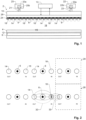
- Fig. 1 illustrates a general setup of an embodiment of the invention. It shows a print head 2, which is used to print ink onto a target 4.
- Print head 2 has e.g. the basic design as described in US 2018/0009223 and comprises an array of nozzles 6 for ejecting inks. As described in more detail in an embodiment below, nozzle electrodes located at the nozzles 6 are used to electrohydrodynamically eject ink droplets from the nozzles 6 and an acceleration electrode accelerates ink from the nozzles onto target 4.
- a target holder 8 is arranged below print head 2 and adapted to hold target 4 at a distance of e.g. 0.1 to 2 mm below print head 2.
- Target holder 8 may e.g. form said acceleration electrode.
- the acceleration electrode is associated with the target 4 such that between the two flat surfaces of target 4 and print head 2 a uniform electric can form which accelerates the droplets ejected from any nozzle 6 in perpendicular direction to the print head 2 surface towards target 4 where they are being deposited.
- Print head 2 may comprise, and/or be thermally connected to, a print head temperature control device 10
- target holder 8 may comprise, and/or be thermally connected to, a target temperature control device 12 to expedite the drying of the ink on substrate 8, by introducing a temperature gradient between print head 2 and target 4.
- Temperature control devices 10, 12 may include a resistive heater or a Peltier element or remote heating or cooling of a liquid which passes through the temperature control device 10, 12.
- passive heating or cooling may be employed, e.g. to bring either print head or target, or both, to room temperature.
- print head temperature control device 10 is adapted to cool or heat the ink itself.
- the ink may be cooled or heated outside print head 2 and then fed into print head 2.
- the ink may be recirculated before being printed.
- the printing system may comprise a circulation pump 13 connected to print head 2 for circulating ink through print head 2, advantageously with the ink being temperature-controlled by print head temperature control device 10. Part of the circulated ink is branched off to the nozzles 6 for printing.
- thermoelectric element for heating or cooling a block of metal or other material with good thermal conductivity, such as Aluminum Nitride, with this block being in contact to the feed layer 26. At the same time, this block may be passed by the ink in which case the ink takes up the temperature of the block before entering the feed layer 26.
- the print head temperature control device 10 sets the print head 2 temperature such that it is lower than the temperature set at the target 4 by the target temperature control device 12. In this way, higher liquid evaporation rates are created at the target 4 than at the print head 2.
- both the absolute temperature at print head 2 and target 4 may be above or below room temperature, while still the print head 2 is at a lower temperature than the target 4 in comparison.
- the temperature at print head 2 may be chosen 50°C while the temperature at the target 4 may be chosen to be 100°C.
- Such high temperatures at target 4 may be chosen in order to not only enhance evaporation of solvent upon droplet impact but in addition the temperature at the target may also introduce some sort of in-situ temperature sintering of the deposited material contained within the ink.
- a lower boiling point liquid may be operated with a lower median temperature than a higher boiling point liquid, wherein median temperature described the intermediate temperature between target 4 and print head 2.
- print head 2 comprises a plurality of ventilation openings, which include blow openings 14 and suction openings 16.
- the blow openings 14 are used to feed gas to a region 18 below the nozzles 6.
- the suction openings 16 are used to feed gas away from region 18.
- a gas source 20 may comprise a pump or pressure reservoir, and optionally a mass flow controller 20a connected in series to an inlet 21 of the print head.
- the gas sink 22 may comprise a vacuum pump or low pressure reservoir, and optionally a mass flow controller 22a connected in series to an outlet 23 of the print head.
- the mass flow controller comprises a mass flow sensor, a pressure regulator, and a fast switching piezo valve 20b, 22b connected in series.
- the piezo valve is used for fast on/off switching of the gas source to the inlet or gas sink to the outlet.
- the steady state gas flow is controlled by the pressure regulator, using the mass flow sensor as feedback device.
- the pressure at the pressure regulator may also be set above the requirements for the steady state flow, to improve transient behavior.
- the piezo valve is operated in a linear proportional mode or a pulse width modulated mode to limit and control the steady state flow.
- the pressure regulator can be entirely omitted by using two fast switching piezo valves in a half-bridge configuration and a pressure sensor, applying the aforementioned in a linear proportional or pulse width modulated driving mode.
- Fast switching of the gas flow between on-state and idle state of the print head is beneficial because the gas flow is advantageously adjusted to the printing flow rate and drying speed of ink on the target 4.
- printing flow rate may rapidly go to zero, in which case the gas flow is advantageously reduced to zero as well, in order to not accelerate evaporation of liquid from the nozzle.
- Commercial mass flow controllers enable precise gas flow control and settling times in the order of 100 milliseconds. Faster switching and settling times in the order of 1 to 10 milliseconds or even below 1 millisecond are achieved with piezo valves.
- the printing system of the present invention may include at least one mass flow controller for regulating (i.e. measuring and maintaining at a desired level) the mass flow of the gas passing through the ventilation openings 14, 16 and/or a valve 20b, 22b for controlling the flow of the gas.
- Print head 2 comprises a nozzle layer 24, which includes the nozzles 6 as well as the nozzle electrodes, and feed layer 26.
- Feed layer 26 forms feed ducts for feeding ink to the nozzles as well as ventilation ducts connecting the ventilation openings 14, 16 to their respective gas source 20 and gas sink 22.
- the arrangement of the nozzles 6 and the ventilation openings 14, 16 can affect the trajectory of the ink through region 18, as well as the drying behavior of ink at substrate and nozzle and it should therefore be designed with care.
- Fig. 2 illustrates a first embodiment, which corresponds to the design illustrated in Fig. 1 .
- each nozzle 6 is arranged between one blow opening 14 and one suction opening 16 (i.e. on the connecting line between the blow opening 14 and the suction opening 16).
- the nozzle 6 is arranged at the center between these two ventilation openings 14, 16.
- Fig. 2 shows two rows of nozzles 6 and ventilation openings 14, 16 extending parallel to each other. It depicts only a small part of the array of nozzles 6 and ventilation openings 14, 16 of the array.
- the array can be divided into a plurality of unit cells 28.
- Fig. 2 illustrates two such unit cells 28, each surrounded by a dotted square.
- Each unit cell 28 advantageously comprises at least one nozzle 6, at least part of a blow opening 14, and at least part of a suction opening 16 in order to generate a controlled, local gas flow around the nozzle 6.
- each unit cell 28 contains exactly one nozzle 6, its neighboring blow opening 14 and its neighboring suction opening 16.
- the gas flow generated by the ventilation openings 14, 16 is illustrated by dashed arrows 30.
- Fig. 3 shows another embodiment of the arrangement of nozzles 6 and ventilation openings 14, 16.
- each unit cell 28 consists of two halves a blow opening 14 and two halves a suction opening 16 alternatingly arranged at the centers of the edges of a square 32 (which coincides with the border of unit cell 28) and one nozzle 6 in the center of square 32.
- Fig. 4 shows a third embodiment of the arrangement of nozzles 6 and ventilation openings 14, 16.
- each unit cell 28 consists of four quarters of suction openings 16 at the corner of a first square 34, four halves of blow openings at the middle of the edges of the first square 34, and one suction opening 16 in the center of the first square 34.
- the unit cell includes four nozzles 6 at the corners of a second square 36.
- the first and second squares 34, 36 have parallel edges and are concentric, and the first square 34 has twice the diameter of the second square 36.
- each unit cell 28 in the embodiment of Fig. 4 may also be offset by one nozzle distance (e.g. to the right in the figure).
- each unit cell 28 consists of four quarters of blow openings 14 at the corner of first square 34, four halves of suction openings 16 at the middle of the edges of first square 34, and one blow opening 14 in the center of the first square 34.
- the unit cell can be described in more than one way, with the descriptions being interchangeable in that they describe the same physical arrangement of the nozzles 8 and the ventilation openings 14, 16.
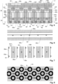
- Figs. 5 - 8 illustrate a possible design of the nozzle layer 24 and the feed layer 26 of a print head 2.
- the design of the nozzles 6 in nozzle layer 24 substantially corresponds to the design of the device described in US 2018/0009223 .
- each nozzle 6 comprises a spout 40 arranged in a recess 42.
- at least one nozzle electrode 44 surrounds recess 42 and is used to extract ink away from a liquid meniscus formed at spout 40.
- the nozzle electrodes 44 are annular (cf. Fig. 8 ).
- an optional shield electrode 46 is arranged at a level below the nozzle electrodes 44. It covers substantially all the array of nozzles 6 with the exception of openings at the location of each nozzle 6 and helps to shield the influence of nozzle electrodes 44 of neighboring nozzle 6 and to maintain a uniform electrical field in region 18.
- Nozzle layer 24 may comprise a first dielectric sublayer 48 between the electrodes 44, 46 and a second dielectric sublayer 50 right above the nozzle electrodes 44.
- a third dielectric sublayer 52 forms the spouts 40.
- a fourth dielectric sublayer 54 forms a carrier membrane of the spouts 40 for positioning and holding each spout 40 at the center of its recess 42.
- Feed layer 26 forms feed ducts 56a, 56b for feeding ink to the nozzles 6.
- they include via sections 56a extending vertically upwards from the nozzles 6 and horizontal interconnect sections 56b. The latter run e.g. perpendicular to the sectional plane of Fig. 5 , and each of them interconnects a plurality of the via sections 56a.
- the interconnect sections 56b may be connected to larger ink terminals of print head 2, where an ink reservoir may be connected to them.
- the ventilation openings 14, 16 are connected to ventilation ducts 58a, 58b, 58c, which extend through print head 2 to ventilation terminals 60, which can be connected to the gas source 20 and to the gas sink 22.
- the ventilation ducts 58a, 58b, 58c include chimney sections 58a, which extend from the ventilation openings 14, 16 vertically through at least part of print head 2, in particular through nozzle layer 24 and at least part of feed layer 26.
- Ventilation ducts 58a, 58b, 58c include two sets of interconnect ducts 58b, 58c, each of which interconnects a plurality or all of the ventilation openings 14, 16.
- the interconnect ducts 58b, 58c advantageously extend horizontally through print head 2.
- the first set 58b of interconnect ducts interconnects the blow openings 14, and the second set 58c of interconnect ducts interconnects the suction openings 16 (or vice versa).
- the two sets form distinct duct systems for feeding gas to the blow openings 14 and for feeding gas away from the suction openings 16.
- an arrangement of ventilation openings is shown that is essentially equal to that shown in Fig. 3 .
- the first and second set of interconnect ducts 58b, 58c are located at different vertical levels in the print head, which makes it easier to keep them separate.
- a single vertical ventilation duct may be formed to continue gas flow to the next higher level of the feed layer 26.
- space is created for the formation of interconnect ducts of different gas pressure (i.e. dedicated to suction of blowing) or of horizontal interconnect sections carrying ink. This can be important for other embodiments than that shown in Fig. 3 .
- Fig. 4 would not allow interconnection of the ventilation ducts 58a of either suction or blowing type, without passing over of ventilation ducts 58a of the other type (i.e. blowing or suction) or over feed ducts 56a.
- This may e.g. be achieved by adjusting the average cross-section and length of uniform ventilation ducts, e.g. chimney section 58a, as compared to their non-uniform counterparts, e.g. of the interconnect ducts 58b, 58c.
- a smaller cross-section and longer length of a given ventilation duct thereby implies a higher pressure drop.
- one way of achieving appreciable results is by reducing the diameter of the blow openings 14 and the suction openings 16 until the pressure drop over uniform parts of the ventilation ducts on averages varies less than a certain percentage. Preferably, such percentage is less than 25% across all blow openings 14 and suction openings 16, more preferably less than 5%.
- operating the print head advantageously comprises at least one of the following steps:
- feed layer 26 comprises several sublayers, which are advantageously of a dielectric material in order to insulate the various electrically conductive tracks within feed layer 26 (to be described below).
- a first sublayer 62a forms the via sections 56a as well as part of the chimney sections 58a.
- a second sublayer 62b forms the interconnect sections 56b of the ink feed ducts for the ink.
- the chimney sections 58a extend through this second sublayer 62b.
- a third sublayer 62c covers second sublayer 62b and closes the interconnect sections 56b from above.
- the chimney sections 58a extend through this third sublayer 62b.
- the third sublayer 62b may also form at least one via section from each interconnect section 56b.
- the same via section may also extend upwards into each of the higher sublayers until there is formed an opening in the topmost layer which allows contacting to an ink source via an ink terminal.
- one such via section 56c and the respective ink port 56d are illustrated, in dotted lines. This exemplifies that after interconnecting feed ducts only few via sections need to be effectively formed all the way to the topmost layer.
- a fourth sublayer 62d forms the first set 58b of interconnect ducts for the gas to the blow openings 14.
- the chimney sections 58a associated with suction openings 16 extend through this fourth sublayer 62d
- a fifth sublayer 62e covers fourth sublayer 62d and closes the interconnect ducts 58b from above.
- the chimney sections 58a associated with suction openings 16 extend through this fourth sublayer 62e.
- a sixth sublayer 62f forms the second set 58c of interconnect ducts for the gas from the suction openings 16.
- the sixth sublayer 62f may also form at least one chimney section from each interconnect duct of the first set of interconnect ducts 58b.
- the same chimney section may also extend into each of the following upper sublayers, until there is formed an opening in the topmost layer in the form of a gas terminal 60 (not shown).
- a seventh sublayer 62g covers sixth sublayer 62f and closes the second set of 58c interconnect ducts from above. It may also form one or more of the gas terminals 60.
- They may include suitable electrical vias extending through some or all of the sublayers of the print head.
- print head 2 may contain electrically conductive vias 64 extending at least through part of the ventilation ducts 58a, 58b, 58c.
- electrically conductive vias 64 may extend along at least some of the chimney sections 58a. They may e.g. be formed by an electrically conductive coating extending along at least part of the wall of the respective chimney section 58a.
- the conductive vias 64 may be connected to the nozzle electrodes 44 as shown in Fig. 8 .
- one half of the vias 64 may be connected to a first set of electrically conductive interconnect lines 66a, e.g. at top surface of sublayer 62c (see Fig. 7 ), while the other half of the vias 64 may be connected to a second set of electrically conductive interconnect lines 66b, e.g. at the top surface of sublayer 62e.
- electrically conducting vias 64 in chimney sections 58a may also be used, in addition or alternatively to the above application, to feed voltage to any other electrode(s) in print head 2, such as to shield electrode 46.
- the print head is to be brought to a specific temperature, it is advantageous to at least form some of the electrical vias 64 as separate vias which are completely filled with metal, e.g. by electroplating or by printing a metal ink into the voids.
- a metal with good thermal conductivity like copper can be used to fill such vias.
- the temperature implied onto the print head by a cooling or a heating device is efficiently forwarded to the nozzle layer, across the dielectric layers of the feed layer which by definition do not have very good thermal conductivity properties.
- nozzle layer 24 of print head 2 as well as feed layer 26, form a single, integral body. They may e.g. be manufactured using masking and etching steps as they are known from semiconductor technology.
- feed layer 26 may be made by stacking and patterning of permanent dry film resist, e.g. epoxy-based dry film resist, or from individual patterned glass sheet, particularly laser-patterned glass sheets, which are bonded together, e.g. by adhesive bonding.
- permanent dry film resist e.g. epoxy-based dry film resist
- individual patterned glass sheet particularly laser-patterned glass sheets, which are bonded together, e.g. by adhesive bonding.
- the print head is operated by applying suitable voltage pulses to the nozzle electrodes 44 in order to eject ink from the nozzles 6 onto target 4.
- gas is conveyed through the ventilation openings 14, 16.
- the steps of printing the ink and conveying the gas are concurrent even though they may also take place intermittently as described for an example below.
- the flow rate of gas conveyed through the blow openings 14 to region 18 e.g. the gas volume conveyed each second into region 18
- the flow rate of gas conveyed through the suction openings 16 from region 18 e.g. the gas volume conveyed each second from region 18
- region 18 may be flooded with fresh gas from the blow openings 14, or it may be flooded with fresh gas drawn in horizontally from the edges of region 18 while the old gas is removed by means of the suction openings 16.
- printing may advantageously be interrupted while operating the gas flow in order to avoid asymmetric deflection caused by the gas flow in region 18.
- the gas flow is advantageously deactivated while the temperature difference between print head 2 and target 4 is upheld.
- the lack of liquid on the target implies that the gas flow will end up supporting removal of liquid from the nozzle, due to the absence of a diffusive gas flow from the target towards to print head.
- a gas may be switched from a partially saturated to a fully saturated species.
- the gas conveyed to region 18 through the blow openings 14 may fulfill one or more of the following functions:
- gas can also be used for both, to support drying and introduce a chemically inert environment
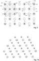
- Fig. 11 shows another advantageous technique for a print head 2 with ventilation openings 14, 16, which does not form part of the invention. It is illustrated, by way of example, for the geometry of nozzles 6 and ventilation openings 14, 16 of Fig. 3 , but it can be combined with any of the embodiments described herein.
- the figure depicts the edge region of the print head, with reference number 70 denoting, symbolically, two edges of the print head.
- the blow openings 14 are denoted by a plus sign and the suction openings 16 by a minus sign.
- the nozzles 6 are represented by small, black dots.
- Fig. 11 further shows the outer border 72 of the active nozzles 6.
- the nozzles 6 to the left of the border 72, in a core region 74 of print head 2 are structured thus that they can be activated for printing. When printing, they are being activated to eject ink.
- blow openings 14 and/or suction openings 16 extend along a row, in particular along a single row, parallel to border 72.
- the print head advantageously comprises a core region 74 with activatable nozzles 6 and ventilation openings 14, 16 and an edge region 76, surrounding the core region 74, with ventilation openings 14', 16' but no activatable nozzles 6, with a (virtual) border 72 between them.
- Ventilation openings 14', 16', 16" have, in the embodiment of Fig. 11 , smaller diameter than the ventilation openings 14, 16 in core region 74, thereby generating a smaller gas flow rate.
- This design takes into account that the ventilation openings 14', 16', 16" along the edge have fewer neighboring ventilation openings than those in core region 74. Thus, reducing the gas flow through them makes the flow pattern of the print head more homogeneous at the location of the outmost active nozzles 6.
- the print head is adapted and structured to generate a smaller gas flow rate through at least some of the ventilation openings 14', 16', 16" in the outmost row than through the ventilation openings 14, 16 in the core region 74.
- the outmost ventilation openings 14', 16' along the edges (but not the ventilation openings 16" at the corners) outside core region 74 have, in the embodiment of Fig. 11 , have only three instead of four neighboring ventilation openings, and therefore the gas flow through them is advantageously approximately 75% of the gas flow through the ventilation openings 14, 16 in the core region.
- the gas flow through the ventilation openings 16" outside the corners of core region 74 should advantageously be adapted to have approximately 50% of the gas flow through the ventilation openings 14, 16 in core region 74.
- the gas flow reduction is implemented, as mentioned, by a diameter reduction of the outmost ventilation openings 14', 16', 16".
- the amount of diameter reduction depends on the length and geometry of ventilation openings and the ventilation ducts and can be calculated using numerical simulation and/or approximating calculations.
- the diameters of the ventilation ducts leading to these ventilation openings may be reduced.
- separate gas sources and/or gas sinks can be provided for core region 74 and edge region 76, with the latter having lower pressure for lower gas flows than the former.
- Fig. 12 shows a design according to the invention for reducing inhomogeneous gas flow at the edge of core region 74.
- edge region 76 is several rows of ventilation openings deep, but the ventilation openings 14', 16' in edge region 76 advantageously have the same gas flow (at least close to border 72) as those in core region 74.
- the distance W from the border 72 to the outmost ventilation openings 14', 16' of the edge region 76 is at least two times, in particular at least five times, the average inter-nozzle distance D of in core region 74 along the direction perpendicular to border 72.
- the method for operating the print head advantageously comprises not ejecting any ink from edge region 76 while it does comprise the step of ejecting ink from the nozzles 6 in core region 74.
- edge regions 76 is based on the understanding that the gas flow pattern generated by the ventilation openings tends to become inhomogeneous at the edge of the area covered by ventilation openings, i.e. leading to a non-homogeneous distribution of evaporated ink, and to non-uniform airflow patterns that may cause slight flight path deviations between the droplets ejected by different nozzles. Hence, for homogeneous printing results, it is advantageous not to have activatable nozzles in edge region 76.
- the print head is adapted and structured to generate a smaller gas flow rate through at least some of the ventilation openings 14', 16' in edge region 76 than through the ventilation openings 14, 16 in core region 74.
- This can e.g. be achieved, as illustrated in Fig. 11 , by providing at least some of the ventilation openings in edge region 76 with a diameter smaller, in particular at least 5% smaller, than the ventilation openings 14, 16 in core region 74.
- the method for operating the print head advantageously comprises feeding a larger amount of gas through at least some of the ventilation openings 14, 16 of core region 74 than through at least some of the ventilation openings 14, 16 of edge region 76, advantageously with an at least 20% smaller gas flow.
- print head 2 may comprise further nozzles outside said array, e.g. nozzles dedicated to special printing tasks. These further nozzles are advantageously fewer in number (e.g. no more than 10% of all nozzles) and they may or may not be provided with their own ventilation openings.
- the unit cells 28 are squares. It must be noted, though, that they may also be mere rectangles. There is no strict need to have equal nozzle spacing in two perpendicular horizontal directions even though, depending on unit cell design, the higher geometry of a square over a rectangle may be advantageous for maintaining identical gas flows around the nozzles.
- nozzles must not be placed in square-like fashion but may also be placed in a hexagonal fashion. For example, this would be achieved by adding a nozzle 8 to the print head 2 in Fig. 3 at all those positions that form the center of a square which has its edges situated at the position of four neighboring nozzles 8. In this way, the number of nozzles 8 on the print head would be doubled while the number of ventilation openings 14, 16 remains constant, i.e. there will be only one ventilation opening 14, 16 per nozzle 8, and hence there is no more symmetry at the level of a single nozzle, similar to the situation in Fig. 4 . This is illustrated in Fig. 9 .
- Fig. 10 finally illustrates a design with the nozzles arranged with 3-fold symmetry.
Landscapes
- Particle Formation And Scattering Control In Inkjet Printers (AREA)
- Ink Jet (AREA)
Claims (30)
- Ein Druckkopf zum Auftragen von Tinte auf ein Substrat, umfassendeine Düsenschicht (24), umfassenda) eine Vielzahl von Düsen (6) undb) eine Vielzahl von Belüftungsöffnungen (14, 16), die sich durch die Düsenschicht (24) erstrecken und dazu ausgestaltet sind, ein Gas zu einem Bereich zwischen dem Druckkopf und einem Ziel zuzuführen und/oder Gas vom Bereich wegzuleiten,wobei der Druckkopf einen Kernbereich (74) mit aktivierbaren Düsen (6) und Belüftungsöffnungen (14, 16) umfasst,wobei der Druckkopfeinen Randbereich (76) mit Belüftungsöffnungen (14, 16), aber ohne aktivierbare Düsen (6) umfasst,mit einem sich zwischen dem Kernbereich (74) und dem Randbereich (76) erstreckenden Rand (72),dadurch gekennzeichnet, dass der Randbereich (76) mehrere Reihen von Belüftungsöffnungen (14, 16) tief ist, wobei ein Abstand (W) vom Rand (72) zu den äussersten Belüftungsöffnungen (14, 16) des Randbereichs (76) mindestens das Zweifache, insbesondere mindestens das fünffache, eines durchschnittlichen Abstands zwischen den Düsen (D) im Kernbereich (74) entlang einer Richtung senkrecht zum Rand (72) beträgt.
- Der Druckkopf nach Anspruch 1, wobei die Belüftungsöffnungen (14, 16) Ansaugöffnungen (16) zum Abführen von Gas aus einem an die Düsen (6) angrenzenden Bereich (18) und Blasöffnungen (14) zum Zuführen von Gas in Richtung des Bereichs (18) umfassen.
- Der Druckkopf nach einem der vorangehenden Ansprüche, umfassend einen Array von Düsen (6) und für jede Düse (6) im Array mindestens eine Belüftungsöffnung (14, 16), insbesondere genau eine Belüftungsöffnung (14, 16) pro Düse.
- Der Druckkopf nach Anspruch 3, der für jede Düse (6) im Array mindestens zwei, insbesondere genau zwei, Belüftungsöffnungen (14, 16) pro Düse umfasst.
- Der Druckkopf nach einem der Ansprüche 3 oder 4, wobei der Array eine Vielzahl identischer Einheitszellen (28) aufweist, wobei jede Einheitszelle (28) mindestens eine Düse (6) und den gleichen Array von Belüftungsöffnungen (14, 16) umfasst.
- Der Druckkopf nach einem der Ansprüche 2 und 5, wobei jede Einheitszelle (28) mindestens einen Teil einer Blasöffnung (14) und mindestens einen Teil einer Saugöffnung (16) umfasst.
- Der Druckkopf nach Anspruch 6, wobei jede Einheitszelle (28) aus einer Blasöffnung (14), einer Saugöffnung (16) und einer Düse (6) besteht, die zwischen der Blasöffnung (14) und der Saugöffnung (16) angeordnet ist, insbesondere in der Mitte zwischen der Blasöffnung (14) und der Saugöffnung (16).
- Der Druckkopf nach Anspruch 6, wobei jede Einheitszelle (28) aus zwei Hälften einer Blasöffnung (14) und zwei Hälften einer Saugöffnung (16) besteht, die abwechselnd an den Mittelpunkten der Kanten eines Rechtecks (32) angeordnet sind, und einer Düse (6) in der Mitte des Rechtecks (32), und wobei insbesondere das Rechteck (32) ein Quadrat ist.
- Der Druckkopf nach Anspruch 6, wobei jede Einheitszelle (28) aus vier Vierteln von Saugöffnungen (16) an der Ecke eines ersten Rechtecks (34), vier Hälften von Blasöffnungen (14) in der Mitte der Kanten des ersten Rechtecks (34), einer Saugöffnung (16) in der Mitte des ersten Rechtecks (34) und vier Düsen (6) an den Ecken eines zweiten Rechtecks (36) besteht, wobei das erste und das zweite Rechteck (34, 36) parallele Kanten aufweisen und konzentrisch sind, und wobei das erste Rechteck (34) den doppelten Durchmesser des zweiten Rechtecks (36) aufweist, und insbesondere wobei die Rechtecke (34, 36) Quadrate sind.
- Der Druckkopf nach einem der vorangehenden Ansprüche, umfassend Lüftungskanäle (58a, 58b, 58c), die mit den Lüftungsöffnungen (14, 16) verbunden sind.
- Der Druckkopf nach Anspruch 10, wobei die Belüftungskanäle (58a, 58b, 58c) Verbindungskanäle (58b, 58c) umfassen, wobei jeder Verbindungskanal (58b, 58c) eine Vielzahl der Belüftungsöffnungen (14, 16) miteinander verbindet, und insbesondere wobei die Verbindungskanäle (58b, 58c) parallel zur Düsenschicht (24) verlaufen.
- Der Druckkopf nach den Ansprüchen 2 und 11, umfassend einen ersten Satz (58b) von Verbindungskanälen, die die Blasöffnungen (14) verbinden, und einen zweiten Satz (58c) von Verbindungskanälen, die die Saugöffnungen (16) verbinden.
- Der Druckkopf nach einem der Ansprüche 10 bis 12, umfassend elektrisch leitende Durchkontaktierungen, die sich durch mindestens einen Teil der Belüftungskanäle (58a, 58b, 58c) erstrecken.
- Der Druckkopf nach einem der vorangehenden Ansprüche, wobei die Düsenschicht (24) ein einzelner, integraler Körper ist.
- Der Druckkopf nach einem der vorangehenden Ansprüche, wobei der Druckkopf ein elektrohydrodynamischer Druckkopf ist, der mindestens eine Düsenelektrode (44) an jeder Düse (6) umfasst.
- Der Druckkopf eines der vorangehenden Ansprüche, umfassend einen Kernbereich (74) mit aktivierbaren Düsen (6) und Belüftungsöffnungen (14, 16) und eine äusserste Reihe von Belüftungsöffnungen (14', 16') umfasst, die den Kernbereich (74) umgeben, wobei der Druckkopf derart ausgestaltet und aufgebaut ist, dass er eine kleinere Gasflussrate durch mindestens einige der Belüftungsöffnungen (14', 16') in der äussersten Reihe als durch die Belüftungsöffnungen (14, 16) im Kernbereich (74) erzeugt.
- Ein Drucksystem mit einem Druckkopf (2) nach einem der vorangehenden Ansprüche.
- Das Drucksystem nach Anspruch 17, umfassend einen Zielhalter (8) und mindestens eine Temperatur-Steuervorrichtung (10) zum Heizen oder Kühlen des Druckkopfes (2) und/oder des Zielhalters (8).
- Das Drucksystem nach Anspruch 18, umfassendeine Druckkopftemperatur-Steuervorrichtung (10) zum Kühlen des Druckkopfes und/odereine Zieltemperatur-Steuervorrichtung (12) zum Heizen des Zielhalters (8).
- Das Drucksystem nach einem der Ansprüche 17 bis 19, weiter umfassend eine Tintenzirkulationspumpe (13), die mit dem Druckkopf (2) verbunden ist.
- Das Drucksystem nach einem der Ansprüche 17 bis 20, umfassend mindestens einen Massendurchflussregler (20a) zum Regulieren eines Massendurchflusses eines Gases, das durch die Belüftungsöffnungen (14, 16) strömt, und/oder ein Ventil (20b, 22b) zum Steuern des Gasflusses.
- Das Drucksystem nach einem der Ansprüche 17 bis 21, weiter umfassend eine Beschleunigungselektrode, die mit einem Ziel verbunden ist, um ein gleichförmiges elektrisches Feld zwischen dem Ziel und dem Druckkopf (2) zu erzeugen, um Tröpfchen, die aus einer beliebigen Düse ausgestossen werden, in Richtung des Ziels (4) zu beschleunigen.
- Ein Verfahren zum Betreiben des Druckkopfes nach einem der vorangehenden Ansprüche, umfassenddas Drucken einer Tinte auf ein Ziel (4) mittels der Düsen (6) unddas Fördern eines Gases durch die Belüftungsöffnungen (14, 16).
- Das Verfahren nach Anspruch 23, wobei einige der Belüftungsöffnungen (14, 16) Blasöffnungen (14) und andere der Belüftungsöffnungen (14, 16) Saugöffnungen (16) sind, wobei das Verfahren umfasst,Wegführen von Gas von einem Bereich (18) an den Düsen (6) durch die Saugöffnungen (16) undZuführen von Gas zum Bereich (18) durch die Blasöffnungen (14),und insbesondere wobei Gas vom Bereich (18) weggeführt und gleichzeitig zum Bereich (18) geführt wird.
- Das Verfahren nach Anspruch 24, wobei eine Strömungsrate von Gas, das durch die Blasöffnungen (14) in den Bereich (18) befördert wird, gleich einer Strömungsrate von Gas ist, das durch die Saugöffnungen (16) aus dem Bereich (18) befördert wird.
- Das Verfahren nach einem der Ansprüche 23 oder 24, wobei elektrische Felder von Düsenelektroden (44) des Druckkopfes verwendet werden, um die Tinte während des Druckens aus den Düsen (6) auszustossen.
- Das Verfahren nach einem der Ansprüche 23 bis 26, umfassend den Schritt des Steuerns der Temperatur von mindestens einem von: dem Druckkopf (2) und dem Ziel (4).
- Das Verfahren nach Anspruch 27, umfassend den Schritt, das Ziel (4) auf einer höheren Temperatur als der Druckkopf (2) zu halten, und insbesondere mit einer Temperaturdifferenz zwischen dem Ziel (4) und dem Druckkopf (2) von mindestens 10°C, insbesondere mindestens 30°C.
- Das Verfahren nach einem der Ansprüche 23 bis 28, umfassend den Schritt des Erwärmens des Ziels (4), insbesondere auf mindestens 80°C.
- Das Verfahren nach einem der Ansprüche, das mindestens einen der Schritte umfasst,Zuführen eines Gases durch mindestens einen Einlass (21) des Druckkopfes (2) zu einer Vielzahl von Blasöffnungen (14) des Druckkopfes (2), wobei ein Strömungswiderstand des Gases zwischen dem mindestens einen Einlass (21) und den Blasöffnungen (14) über alle Blasöffnungen (14) um weniger als 25%, insbesondere weniger als 5%, variiert, und/oderZuführen eines Gases von Ansaugöffnungen (16) des Druckkopfes durch mindestens einen Auslass (23) des Druckkopfes (2), wobei ein Strömungswiderstand des Gases zwischen den Ansaugöffnungen (16) und dem mindestens einen Auslass (23) über alle Ansaugöffnungen (16) um weniger als 25%, insbesondere weniger als 5%, variiert.
Applications Claiming Priority (2)
| Application Number | Priority Date | Filing Date | Title |
|---|---|---|---|
| PCT/EP2019/069212 WO2021008698A1 (en) | 2019-07-17 | 2019-07-17 | Ventilated print head |
| PCT/EP2020/067327 WO2021008817A1 (en) | 2019-07-17 | 2020-06-22 | Ventilated print head |
Publications (3)
| Publication Number | Publication Date |
|---|---|
| EP3969286A1 EP3969286A1 (de) | 2022-03-23 |
| EP3969286C0 EP3969286C0 (de) | 2025-02-26 |
| EP3969286B1 true EP3969286B1 (de) | 2025-02-26 |
Family
ID=67539420
Family Applications (1)
| Application Number | Title | Priority Date | Filing Date |
|---|---|---|---|
| EP20733310.5A Active EP3969286B1 (de) | 2019-07-17 | 2020-06-22 | Belüfteter druckkopf |
Country Status (8)
| Country | Link |
|---|---|
| US (1) | US11840084B2 (de) |
| EP (1) | EP3969286B1 (de) |
| JP (1) | JP7573593B2 (de) |
| KR (1) | KR20220044268A (de) |
| CN (1) | CN114126877B (de) |
| IL (1) | IL289647B2 (de) |
| TW (1) | TWI878321B (de) |
| WO (2) | WO2021008698A1 (de) |
Families Citing this family (8)
| Publication number | Priority date | Publication date | Assignee | Title |
|---|---|---|---|---|
| WO2022174907A1 (en) * | 2021-02-18 | 2022-08-25 | Scrona Ag | Inkjet printing system with nozzle evaporator |
| PL4272967T3 (pl) * | 2022-05-05 | 2025-03-31 | SWISS KRONO Tec AG | Sposób zadruku przedmiotu i urządzenie do druku cyfrowego zawierające środki ograniczające tworzenie się kondensatu przy zadrukowywaniu przedmiotu |
| EP4272966B1 (de) * | 2022-05-05 | 2024-10-09 | SWISS KRONO Tec AG | Verfahren zum bedrucken eines papiers und digitaldruckeinrichtung umfassend mittels zum reduzieren von kondensatbildung |
| KR20250078902A (ko) | 2022-08-11 | 2025-06-04 | 스크로나 아게 | 분배식 공급 구조물을 갖는 전자유체역학적 프린트 헤드 |
| CN119998129A (zh) * | 2022-09-30 | 2025-05-13 | 赛尔科技有限公司 | 用于液滴喷射头的致动器部件及其制造方法 |
| CN116278387B (zh) * | 2023-03-29 | 2025-08-22 | 合肥京东方卓印科技有限公司 | 一种喷墨打印装置、其打印方法以及喷墨打印系统 |
| WO2024260569A1 (en) | 2023-06-23 | 2024-12-26 | Scrona Ag | Printing-assisted hybrid bonding technique |
| JP2025146070A (ja) * | 2024-03-22 | 2025-10-03 | 株式会社リコー | 液滴吐出ヘッド、ヘッドユニット及び液滴吐出装置 |
Family Cites Families (27)
| Publication number | Priority date | Publication date | Assignee | Title |
|---|---|---|---|---|
| DE3269768D1 (en) | 1981-01-21 | 1986-04-17 | Matsushita Electric Industrial Co Ltd | Ink jet printing head utilizing pressure and potential gradients |
| JPS59138461A (ja) * | 1983-01-28 | 1984-08-08 | Canon Inc | 液体噴射記録装置 |
| US4829325A (en) * | 1986-11-14 | 1989-05-09 | Matsushita Electric Industrial Co., Ltd. | Ink jet recording apparatus with an electrode disposed at writing paper side |
| JP2000318181A (ja) * | 1999-05-07 | 2000-11-21 | Canon Aptex Inc | インクジェット記録装置 |
| US6588889B2 (en) * | 2001-07-16 | 2003-07-08 | Eastman Kodak Company | Continuous ink-jet printing apparatus with pre-conditioned air flow |
| JP4617799B2 (ja) * | 2004-09-24 | 2011-01-26 | 富士ゼロックス株式会社 | インクジェット記録ヘッドのメンテナンス方法及びインクジェット記録装置 |
| JP4352019B2 (ja) * | 2005-04-22 | 2009-10-28 | キヤノン株式会社 | インクジェット記録ヘッドおよび該ヘッドを用いるインクジェット記録装置 |
| JP2007008157A (ja) * | 2005-05-30 | 2007-01-18 | Brother Ind Ltd | 液滴噴射装置 |
| FR2924379B1 (fr) * | 2007-11-29 | 2011-04-22 | Imaje Sa | Tete d'impression a jet d'encre a nettoyage automatise au demarrage d'impression |
| JP5084478B2 (ja) * | 2007-12-07 | 2012-11-28 | キヤノン株式会社 | インクジェット記録ヘッドおよびインクジェット記録装置 |
| FR2934809A1 (fr) * | 2008-08-11 | 2010-02-12 | Imaje Sa | Dispositif d'impression a jet d'encre a injecteur d'air, injecteur d'air et tete d'impression grande largeur associes |
| JP5187124B2 (ja) * | 2008-10-16 | 2013-04-24 | セイコーエプソン株式会社 | 液状体の吐出方法、カラーフィルタの製造方法および有機el装置の製造方法 |
| US8931431B2 (en) * | 2009-03-25 | 2015-01-13 | The Regents Of The University Of Michigan | Nozzle geometry for organic vapor jet printing |
| JP2011005422A (ja) * | 2009-06-25 | 2011-01-13 | Kyocera Corp | 液体塗布ヘッドおよびそれを用いた液体塗布装置 |
| US20140176634A1 (en) * | 2012-12-20 | 2014-06-26 | Donald Saul Rimai | Condensation control system for an ink jet printing system |
| US8833900B2 (en) * | 2012-12-20 | 2014-09-16 | Eastman Kodak Company | Inkjet printing system with managed condensation control airflow |
| JP2014208451A (ja) * | 2013-03-29 | 2014-11-06 | キヤノン株式会社 | 液体吐出ヘッド |
| JP6456069B2 (ja) * | 2013-09-20 | 2019-01-23 | キヤノン株式会社 | 液体吐出装置、ミスト回収機構及びミスト回収方法 |
| WO2015200464A1 (en) * | 2014-06-27 | 2015-12-30 | Fujifilm Dimatix, Inc. | High height ink jet printing |
| EP3050706A1 (de) | 2015-01-29 | 2016-08-03 | ETH Zurich | Druckkopf mit mehreren Düsen |
| JP2016159556A (ja) * | 2015-03-03 | 2016-09-05 | キヤノン株式会社 | 液体吐出ヘッド、記録装置および記録方法 |
| US10144217B2 (en) * | 2015-03-03 | 2018-12-04 | Canon Kabushiki Kaisha | Recording apparatus, recording method, and liquid ejection head for recording an image by ejecting liquid droplets toward a recording medium while moving the liquid ejection head and the recording medium relative to each other |
| US10518527B2 (en) | 2015-04-20 | 2019-12-31 | Eth Zurich | Print pattern generation on a substrate |
| JP2016221742A (ja) * | 2015-05-28 | 2016-12-28 | 株式会社リコー | 液体を吐出する装置 |
| US10328694B2 (en) * | 2015-07-31 | 2019-06-25 | Hewlett-Packard Development Company, L.P. | Printed circuit board with recessed pocket for fluid droplet ejection die |
| JP6794624B2 (ja) * | 2015-11-30 | 2020-12-02 | 株式会社リコー | 液体を吐出する装置 |
| JP6695154B2 (ja) * | 2016-01-28 | 2020-05-20 | 東芝テック株式会社 | インク循環装置及びプリンタ |
-
2019
- 2019-07-17 WO PCT/EP2019/069212 patent/WO2021008698A1/en not_active Ceased
-
2020
- 2020-06-22 US US17/627,282 patent/US11840084B2/en active Active
- 2020-06-22 CN CN202080051159.XA patent/CN114126877B/zh active Active
- 2020-06-22 KR KR1020227001625A patent/KR20220044268A/ko active Pending
- 2020-06-22 WO PCT/EP2020/067327 patent/WO2021008817A1/en not_active Ceased
- 2020-06-22 JP JP2022502904A patent/JP7573593B2/ja active Active
- 2020-06-22 EP EP20733310.5A patent/EP3969286B1/de active Active
- 2020-06-22 IL IL289647A patent/IL289647B2/en unknown
- 2020-07-15 TW TW109123830A patent/TWI878321B/zh active
Also Published As
| Publication number | Publication date |
|---|---|
| EP3969286A1 (de) | 2022-03-23 |
| CN114126877A (zh) | 2022-03-01 |
| KR20220044268A (ko) | 2022-04-07 |
| US11840084B2 (en) | 2023-12-12 |
| JP2022541515A (ja) | 2022-09-26 |
| TWI878321B (zh) | 2025-04-01 |
| IL289647A (en) | 2022-03-01 |
| IL289647B1 (en) | 2025-04-01 |
| IL289647B2 (en) | 2025-08-01 |
| WO2021008817A1 (en) | 2021-01-21 |
| JP7573593B2 (ja) | 2024-10-25 |
| TW202110659A (zh) | 2021-03-16 |
| EP3969286C0 (de) | 2025-02-26 |
| WO2021008698A1 (en) | 2021-01-21 |
| CN114126877B (zh) | 2023-08-29 |
| US20220242118A1 (en) | 2022-08-04 |
Similar Documents
| Publication | Publication Date | Title |
|---|---|---|
| EP3969286B1 (de) | Belüfteter druckkopf | |
| KR101886590B1 (ko) | 성형된 유체 유동 구조체 | |
| JP5213451B2 (ja) | 小型エアゾールジェット流及びエアゾールジェット流配列構造 | |
| US9676192B2 (en) | Printbar and method of forming same | |
| US20110181644A1 (en) | Method and Apparatus for Controlling Film Deposition | |
| CN102271922A (zh) | 干墨排放喷嘴的快速充墨 | |
| US6880926B2 (en) | Circulation through compound slots | |
| US11376862B2 (en) | Fluid ejection with micropumps and pressure-difference based fluid flow | |
| KR101684727B1 (ko) | 열 저항기 유체 토출 어셈블리 | |
| US12377653B2 (en) | Inkjet printing system with nozzle evaporator | |
| US20080036820A1 (en) | Apparatus and Method for Jetting Droplet Using Electrostatic Field | |
| US7470016B2 (en) | Introducing material into a printhead enclosure | |
| US10717285B2 (en) | Liquid ejecting apparatus and method of operating liquid ejecting apparatus | |
| JP2021504200A (ja) | 流体循環および吐出 | |
| US11970002B2 (en) | Electrodynamic print head with split shielding electrodes for lateral ink deflection | |
| US20250360710A1 (en) | Electrohydrodynamic print head with distributed feed structure | |
| JP2022113539A (ja) | 液体吐出ヘッド及び液体吐出装置 | |
| CN119017859B (zh) | Dna酶促法制备工艺及其装置 | |
| WO2024034265A1 (ja) | 液滴吐出装置、及び印刷物の製造方法 | |
| KR20240077049A (ko) | 잉크젯 프린터의 잉크 입자 퇴적 방지장치 | |
| JP2023088371A (ja) | 液体吐出ヘッド |
Legal Events
| Date | Code | Title | Description |
|---|---|---|---|
| STAA | Information on the status of an ep patent application or granted ep patent |
Free format text: STATUS: UNKNOWN |
|
| STAA | Information on the status of an ep patent application or granted ep patent |
Free format text: STATUS: THE INTERNATIONAL PUBLICATION HAS BEEN MADE |
|
| PUAI | Public reference made under article 153(3) epc to a published international application that has entered the european phase |
Free format text: ORIGINAL CODE: 0009012 |
|
| STAA | Information on the status of an ep patent application or granted ep patent |
Free format text: STATUS: REQUEST FOR EXAMINATION WAS MADE |
|
| 17P | Request for examination filed |
Effective date: 20211214 |
|
| AK | Designated contracting states |
Kind code of ref document: A1 Designated state(s): AL AT BE BG CH CY CZ DE DK EE ES FI FR GB GR HR HU IE IS IT LI LT LU LV MC MK MT NL NO PL PT RO RS SE SI SK SM TR |
|
| DAV | Request for validation of the european patent (deleted) | ||
| DAX | Request for extension of the european patent (deleted) | ||
| STAA | Information on the status of an ep patent application or granted ep patent |
Free format text: STATUS: EXAMINATION IS IN PROGRESS |
|
| 17Q | First examination report despatched |
Effective date: 20230309 |
|
| GRAP | Despatch of communication of intention to grant a patent |
Free format text: ORIGINAL CODE: EPIDOSNIGR1 |
|
| STAA | Information on the status of an ep patent application or granted ep patent |
Free format text: STATUS: GRANT OF PATENT IS INTENDED |
|
| INTG | Intention to grant announced |
Effective date: 20241018 |
|
| GRAS | Grant fee paid |
Free format text: ORIGINAL CODE: EPIDOSNIGR3 |
|
| GRAA | (expected) grant |
Free format text: ORIGINAL CODE: 0009210 |
|
| STAA | Information on the status of an ep patent application or granted ep patent |
Free format text: STATUS: THE PATENT HAS BEEN GRANTED |
|
| AK | Designated contracting states |
Kind code of ref document: B1 Designated state(s): AL AT BE BG CH CY CZ DE DK EE ES FI FR GB GR HR HU IE IS IT LI LT LU LV MC MK MT NL NO PL PT RO RS SE SI SK SM TR |
|
| REG | Reference to a national code |
Ref country code: GB Ref legal event code: FG4D |
|
| REG | Reference to a national code |
Ref country code: CH Ref legal event code: EP |
|
| REG | Reference to a national code |
Ref country code: DE Ref legal event code: R096 Ref document number: 602020046740 Country of ref document: DE |
|
| REG | Reference to a national code |
Ref country code: IE Ref legal event code: FG4D |
|
| U01 | Request for unitary effect filed |
Effective date: 20250226 |
|
| U07 | Unitary effect registered |
Designated state(s): AT BE BG DE DK EE FI FR IT LT LU LV MT NL PT RO SE SI Effective date: 20250307 |
|
| U20 | Renewal fee for the european patent with unitary effect paid |
Year of fee payment: 6 Effective date: 20250404 |
|
| PG25 | Lapsed in a contracting state [announced via postgrant information from national office to epo] |
Ref country code: RS Free format text: LAPSE BECAUSE OF FAILURE TO SUBMIT A TRANSLATION OF THE DESCRIPTION OR TO PAY THE FEE WITHIN THE PRESCRIBED TIME-LIMIT Effective date: 20250526 |
|
| PG25 | Lapsed in a contracting state [announced via postgrant information from national office to epo] |
Ref country code: PL Free format text: LAPSE BECAUSE OF FAILURE TO SUBMIT A TRANSLATION OF THE DESCRIPTION OR TO PAY THE FEE WITHIN THE PRESCRIBED TIME-LIMIT Effective date: 20250226 |
|
| PG25 | Lapsed in a contracting state [announced via postgrant information from national office to epo] |
Ref country code: ES Free format text: LAPSE BECAUSE OF FAILURE TO SUBMIT A TRANSLATION OF THE DESCRIPTION OR TO PAY THE FEE WITHIN THE PRESCRIBED TIME-LIMIT Effective date: 20250226 |
|
| PGFP | Annual fee paid to national office [announced via postgrant information from national office to epo] |
Ref country code: GB Payment date: 20250618 Year of fee payment: 6 |
|
| PG25 | Lapsed in a contracting state [announced via postgrant information from national office to epo] |
Ref country code: IS Free format text: LAPSE BECAUSE OF FAILURE TO SUBMIT A TRANSLATION OF THE DESCRIPTION OR TO PAY THE FEE WITHIN THE PRESCRIBED TIME-LIMIT Effective date: 20250626 Ref country code: NO Free format text: LAPSE BECAUSE OF FAILURE TO SUBMIT A TRANSLATION OF THE DESCRIPTION OR TO PAY THE FEE WITHIN THE PRESCRIBED TIME-LIMIT Effective date: 20250526 |
|
| PG25 | Lapsed in a contracting state [announced via postgrant information from national office to epo] |
Ref country code: HR Free format text: LAPSE BECAUSE OF FAILURE TO SUBMIT A TRANSLATION OF THE DESCRIPTION OR TO PAY THE FEE WITHIN THE PRESCRIBED TIME-LIMIT Effective date: 20250226 |
|
| PG25 | Lapsed in a contracting state [announced via postgrant information from national office to epo] |
Ref country code: GR Free format text: LAPSE BECAUSE OF FAILURE TO SUBMIT A TRANSLATION OF THE DESCRIPTION OR TO PAY THE FEE WITHIN THE PRESCRIBED TIME-LIMIT Effective date: 20250527 |
|
| PG25 | Lapsed in a contracting state [announced via postgrant information from national office to epo] |
Ref country code: SM Free format text: LAPSE BECAUSE OF FAILURE TO SUBMIT A TRANSLATION OF THE DESCRIPTION OR TO PAY THE FEE WITHIN THE PRESCRIBED TIME-LIMIT Effective date: 20250226 |
|
| PGFP | Annual fee paid to national office [announced via postgrant information from national office to epo] |
Ref country code: CH Payment date: 20250701 Year of fee payment: 6 |
|
| PG25 | Lapsed in a contracting state [announced via postgrant information from national office to epo] |
Ref country code: CZ Free format text: LAPSE BECAUSE OF FAILURE TO SUBMIT A TRANSLATION OF THE DESCRIPTION OR TO PAY THE FEE WITHIN THE PRESCRIBED TIME-LIMIT Effective date: 20250226 |
|
| PG25 | Lapsed in a contracting state [announced via postgrant information from national office to epo] |
Ref country code: SK Free format text: LAPSE BECAUSE OF FAILURE TO SUBMIT A TRANSLATION OF THE DESCRIPTION OR TO PAY THE FEE WITHIN THE PRESCRIBED TIME-LIMIT Effective date: 20250226 |