EP3969191B1 - Dispositif d´utilisation d´un produit d´absorption de fluides repandus avec recyclage de ce produit - Google Patents
Dispositif d´utilisation d´un produit d´absorption de fluides repandus avec recyclage de ce produit Download PDFInfo
- Publication number
- EP3969191B1 EP3969191B1 EP20731929.4A EP20731929A EP3969191B1 EP 3969191 B1 EP3969191 B1 EP 3969191B1 EP 20731929 A EP20731929 A EP 20731929A EP 3969191 B1 EP3969191 B1 EP 3969191B1
- Authority
- EP
- European Patent Office
- Prior art keywords
- receptacle
- sieving
- container
- product
- tank
- Prior art date
- Legal status (The legal status is an assumption and is not a legal conclusion. Google has not performed a legal analysis and makes no representation as to the accuracy of the status listed.)
- Active
Links
Images


Classifications
-
- B—PERFORMING OPERATIONS; TRANSPORTING
- B07—SEPARATING SOLIDS FROM SOLIDS; SORTING
- B07B—SEPARATING SOLIDS FROM SOLIDS BY SIEVING, SCREENING, SIFTING OR BY USING GAS CURRENTS; SEPARATING BY OTHER DRY METHODS APPLICABLE TO BULK MATERIAL, e.g. LOOSE ARTICLES FIT TO BE HANDLED LIKE BULK MATERIAL
- B07B1/00—Sieving, screening, sifting, or sorting solid materials using networks, gratings, grids, or the like
- B07B1/02—Hand screens
-
- B—PERFORMING OPERATIONS; TRANSPORTING
- B07—SEPARATING SOLIDS FROM SOLIDS; SORTING
- B07B—SEPARATING SOLIDS FROM SOLIDS BY SIEVING, SCREENING, SIFTING OR BY USING GAS CURRENTS; SEPARATING BY OTHER DRY METHODS APPLICABLE TO BULK MATERIAL, e.g. LOOSE ARTICLES FIT TO BE HANDLED LIKE BULK MATERIAL
- B07B1/00—Sieving, screening, sifting, or sorting solid materials using networks, gratings, grids, or the like
- B07B1/005—Transportable screening plants
-
- B—PERFORMING OPERATIONS; TRANSPORTING
- B07—SEPARATING SOLIDS FROM SOLIDS; SORTING
- B07B—SEPARATING SOLIDS FROM SOLIDS BY SIEVING, SCREENING, SIFTING OR BY USING GAS CURRENTS; SEPARATING BY OTHER DRY METHODS APPLICABLE TO BULK MATERIAL, e.g. LOOSE ARTICLES FIT TO BE HANDLED LIKE BULK MATERIAL
- B07B13/00—Grading or sorting solid materials by dry methods, not otherwise provided for; Sorting articles otherwise than by indirectly controlled devices
- B07B13/14—Details or accessories
- B07B13/16—Feed or discharge arrangements
-
- B—PERFORMING OPERATIONS; TRANSPORTING
- B09—DISPOSAL OF SOLID WASTE; RECLAMATION OF CONTAMINATED SOIL
- B09C—RECLAMATION OF CONTAMINATED SOIL
- B09C1/00—Reclamation of contaminated soil
Definitions
- the present invention relates to a device for using an absorbent product in powder or granule form, as well as a method for implementing such a device.
- the absorbent product swollen by the fluid is then collected, for example by sweeping, to remove most of the fluid spilled on the floor. Finally, if necessary, a solvent or cleaning product such as detergent can be applied to the floor to ensure that the floor is clean.
- trolleys equipped with all the necessary elements, including a storage bin containing the absorbent product, a receiving bin receiving the soiled absorbent product, and the different tools necessary to carry out these operations such as a broom and a shovel.
- the cleaning staff can move quickly to the scene of the incident to first recover as much of the spilled fluid as possible with the absorbent product, then collect and dispose of this soiled product in the receiving bin. Once the receiving bin is full, the soiled product can be recovered and treated by specialized companies in the best conditions of safety and respect for the environment.
- the document GB2346077 A discloses a device according to the preamble of claim 1.
- the present invention aims in particular to avoid these drawbacks of the prior art.
- a device for using an absorbent product in particular in powder or granule form, to absorb fluids spilled on the ground according to claim 1, comprising a container equipped with a storage tank for this absorbent product, and a tank for receiving the soiled absorbent product, this device being remarkable in that it comprises a sieving receptacle comprising at the bottom a sieve arranged above an opening of the storage tank, which can be emptied into the receiving tank.
- An advantage of the device according to the invention is that after spreading the absorbent product on the ground, the operator simply pours this soiled product into the receptacle equipped with the sieve, then with a vibration obtains a sieving of this product allowing the unsoiled powder or granules to pass through remaining in the form of fine particles, which descend and are recycled in the storage bin. Once this sieving is finished, the operator tilts the receptacle to pour into the receiving bin the remaining product actually soiled, which has agglomerated to form lumps.
- the device for using the absorbent product according to the invention may further comprise one or more of the following characteristics, which may be combined with each other.
- the opening of the storage bin corresponds to the outer contour of this storage bin.
- the screening receptacle has a guide in the container.
- the screening receptacle comprises external shoulders which come above bosses formed inside the container.
- the screening receptacle comprises a handle arranged on a front face of the container, the guidance in the container being carried out in a direction perpendicular to this front face.
- the receiving tray is arranged next to the screening receptacle.
- the screening receptacle has on the upper part of one of its sides a horizontal chute whose end comes above the receiving tank.
- the screening receptacle comprises a shape which rests on an edge of the receiving bin, constituting a pivot allowing the chute to be poured into this receiving bin.
- the sieving receptacle has a sieve with bumps at the bottom.
- the invention also relates to a method for implementing a device for using an absorbent product, in particular in powder or granule form, according to claim 8, comprising an operation of shaking the sieving receptacle along guides above the storage tank, then an operation of tilting the sieving receptacle emptying lumps formed by the soiled product into the receiving tank, and finally an operation of returning the sieving receptacle to its position above the storage tank.
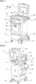
- FIGS. 1 and 2 present a trolley comprising a container 2 having a vertically elongated parallelepiped shape, having a cover 4 fixed by a hinge 6 at the top of the rear side of this container indicated by the arrow AR.
- the base on the right side has an axis arranged along the length receiving two fixed casters 8
- the base on the left side has at each corner a swivel caster along a vertical axis 10 to ensure the mobility of the trolley in all directions.
- the left side of the container 2 has a cell 16 in the upper part which also allows bottles to be accommodated there.
- the right side has an opening 20 at the bottom leading to a lower compartment occupying approximately a quarter of the height of the container 2, allowing various products to be accommodated there.
- a storage bin 22 for an absorbent product in powder or granule form has a front face fitted to the front face of the container, sides fitted inside the right and left sides of the container, and a rear face arranged approximately two-thirds of the length of this container.
- the storage bin 22 is connected to the container 2 by a lower pivot arranged along the width allowing it to tilt forward as shown. figure 2 , a handle 24 formed on the upper part of its front face facilitating this traction.
- Each side of the container 2 has on its inner face a cleat 26 which descends slightly inside the storage bin 22, coming onto an inner shoulder of the bin when it is fully tilted forward in order to prevent this bin from falling.
- the storage bin 22 can be easily opened by pulling it by its handle 24, to release its upper opening forward and to fill it.
- a screening receptacle 30 has a substantially rectangular shape fitting within the width of the container 2, having a forward-facing handle 32 which facilitates its gripping and movement.
- the screening receptacle 30 comprises on each side along its length a horizontal external shoulder 34, forming an overhang which rests on a corresponding boss 36 formed inside the right and left side of the container 2, to constitute guide rails along the length of this container comprising stops at the ends.
- the sieving receptacle 30 comprises a horizontal bottom forming a lower sieve 38, having a passage surface which remains inside the opening of the storage bin 22 during movements using the handle 32 of this receptacle, limited by its stops, to ensure that all of the absorbent product passing through the sieve falls into this bin.
- the sieve 38 has a generally flat horizontal surface comprising bumps distributed over this surface.
- a container for receiving soiled absorbent product 40 having a parallelepiped shape elongated in height has a width fitting inside the two sides of the container 2, a length corresponding to approximately a quarter of the length of this container, and a height corresponding to approximately half the height of the container.
- the rear upper edge of the storage bin 22 has a rearward-facing spoiler 28, which bears on the front face of the receiving bin 40 in order to completely close the passage between these two bins to prevent descents of absorbent product which would fall between them, outside the storage tank.
- the screening receptacle 30 comprises in the upper part of its rear face a horizontal chute 42 extending over the entire width of this rear face, which ends substantially in the middle of the receiving bin 40.
- the receiving bin 40 and the screening receptacle 30 are easily removed by lifting them out of the container 2.
- All of the components of the trolley including in particular the container 2 formed of several assembled panels each constituting a side, the cover 4, the storage bin 22, the sieving receptacle 30 with its sieve 38 and the receiving bin 40, are formed by a plastic molding which makes it possible to economically produce rigid and lightweight elements.
- the operator has on the trolley containing absorbent product in the storage bin 22, a broom, a shovel, cleaning product and accessories such as cloths, so that during an intervention he has all the equipment necessary to pick up a spilled fluid and clean the floor.
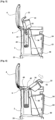
- the operator grasps the handle 32 of the sieving receptacle 30, and applies a vigorous alternating movement along the length by sliding it on its rails to obtain a descent through the sieve 38 of the absorbent product 50 which has not been in contact with the fluid, remaining in the form of powder or granules fine enough not to pass through the sieve.
- the embossing of the sieve 38 facilitates the movement and sorting of the absorbent product, by rolling the lumps 52 formed by the powder or granules agglomerated by the absorbed fluid, and by clearing the meshes of the sieve to allow the clean product to pass through.
- the operator lifts the handle 32, tilting the screening receptacle 30 about a pivot formed by the junction of the chute 42 with the rear face of the screening receptacle 30, rotating about the upper front edge of the receiving bin 40. In this way the screening receptacle 30 is guided, letting the rear end of its chute 42 descend into the receiving bin 40.
- FIG 5 presents a following operation comprising the complete tilting of the sieving receptacle 30, coming into a substantially vertical position, all of the lumps 52 descending into the receiving bin 40.
- the figure 6 presents a following operation comprising the reverse tilting of the sieving receptacle 30 which is empty.
- a subsequent emptying operation of the receiving bin 40 is easily done by lifting the sieving receptacle 30, and the receiving bin 40 which slides vertically to be emptied.
- Another subsequent filling operation of the storage bin 22 is easily done by pulling its handle 24 to tilt it forward, which releases its upper opening allowing it to be filled for example with a shovel, or by emptying a bag into it.
Landscapes
- Life Sciences & Earth Sciences (AREA)
- Soil Sciences (AREA)
- Engineering & Computer Science (AREA)
- Environmental & Geological Engineering (AREA)
- Combined Means For Separation Of Solids (AREA)
- Housing For Livestock And Birds (AREA)
Description
- La présente invention concerne un dispositif d'utilisation d'un produit absorbant en poudre ou en granulés, ainsi qu'un procédé de mise en oeuvre d'un tel dispositif.
- Après l'écoulement d'un fluide sur un sol, en particulier des produits chimiques, des hydrocarbures ou des huiles, il est connu d'utiliser un produit absorbant sous forme de poudre ou granulés, qui est répandu sur les taches afin dans un premier temps d'absorber ce fluide.
- On ramasse ensuite le produit absorbant gonflé par le fluide, par exemple par balayage, pour retirer la majeure partie du fluide répandu sur le sol. On peut enfin si nécessaire passer sur le sol un solvant ou un produit de nettoyage comme une lessive, afin d'assurer la propreté de ce sol.
- Pour ces différentes opérations il est connu d'utiliser des chariots équipés de tous les éléments nécessaires, comportant un bac de stockage contenant le produit absorbant, un bac de réception recevant le produit absorbant souillé, et les différents outils nécessaires pour réaliser ces opérations comme un balai et une pelle.
- De cette manière le personnel de nettoyage peut se déplacer rapidement sur le lieu de l'incident pour d'abord récupérer au maximum le fluide déversé avec le produit absorbant, puis ensuite ramasser et jeter dans le bac de réception ce produit souillé. Une fois le bac de réception rempli, le produit souillé peut être récupéré et traité par des entreprises spécialisées dans les meilleures conditions de sécurité et de respect de l'environnement.
- On notera que certains produits répandus peuvent présenter des risques, comme des produits chimiques dégageant des vapeurs toxiques, des produits gras et glissants pouvant causer des accidents, ou des produits qui finissent par imprégner le sol en les polluant. Le personnel doit pouvoir intervenir rapidement pour effectuer de manière efficace et complète le ramassage.
- Afin d'optimiser les qualités du produit absorbant utilisé, certains fournisseurs ont développé des poudres ou des granulés présentant un pouvoir élevé d'absorption, notamment à base de fibres de cellulose, afin de récupérer de manière rapide et sûr un maximum de fluide répandu.
- Toutefois la totalité du produit absorbant répandu à terre est ensuite jetée dans le bac de récupération ce qui donne une consommation importante de produit, qui peut présenter un coût élevé, et génère une masse de déchets entraînant aussi des coûts pour son élimination.
- Le document
GB2346077 A - La présente invention a notamment pour but d'éviter ces inconvénients de la technique antérieure.
- Elle propose à cet effet un dispositif d'utilisation d'un produit absorbant, notamment en poudre ou en granules, pour absorber des fluides répandus au sol selon la revendication 1, comprenant un container équipé d'un bac de stockage de ce produit absorbant, et d'un bac de réception du produit absorbant souillé, ce dispositif étant remarquable en ce qu'il comporte un réceptacle de tamisage comprenant au fond un tamis disposé au-dessus d'une ouverture du bac de stockage, pouvant être vidé dans le bac de réception.
- Un avantage du dispositif selon l'invention est qu'après l'épandage au sol du produit absorbant, l'opérateur verse simplement ce produit souillé dans le réceptacle équipé du tamis, pour ensuite avec une vibration obtenir un tamisage de ce produit laissant passer la poudre ou les granulés non souillés restant sous forme de particules fines, qui descendent et sont recyclées dans le bac de stockage. Une fois ce tamisage fini l'opérateur bascule le réceptacle pour verser dans le bac de réception le produit restant effectivement souillé, qui s'est aggloméré en formant des grumeaux.
- On obtient ainsi à la fois une récupération maximum du produit absorbant non souillé, qui est prêt à servir pour des opérations suivantes, et une élimination d'un minimum de déchets qui sont effectivement souillés.
- Le dispositif d'utilisation du produit absorbant selon l'invention peut comporter de plus une ou plusieurs des caractéristiques suivantes, qui peuvent être combinées entre elles.
- Avantageusement, l'ouverture du bac de stockage correspond au contour extérieur de ce bac de stockage.
- Selon l'invention, le réceptacle de tamisage comporte un guidage dans le container.
- En outre selon l'invention, le réceptacle de tamisage comporte des épaulements extérieurs qui viennent au-dessus de bossages formés à l'intérieur du container.
- Avantageusement, le réceptacle de tamisage comporte une poignée disposée sur une face avant du container, le guidage dans le container se faisant suivant une direction perpendiculaire à cette face avant.
- Avantageusement, le bac de réception est disposé à côté du réceptacle de tamisage.
- Dans ce cas, avantageusement le réceptacle de tamisage comporte sur la partie supérieure d'un de ses côtés une goulotte horizontale dont l'extrémité vient au-dessus du bac de réception.
- De plus, avantageusement le réceptacle de tamisage comporte une forme venant en appui sur un bord du bac de réception, constituant un pivot permettant de verser la goulotte dans ce bac de réception.
- Avantageusement, le réceptacle de tamisage comporte au fond un tamis présentant des bosselages.
- L'invention a aussi pour objet un procédé de mise en oeuvre d'un dispositif d'utilisation d'un produit absorbant, notamment en poudre ou granules, selon la revendication 8, comportant une opération de secouage du réceptacle de tamisage suivant des guidages au-dessus du bac de stockage, puis une opération de basculement du réceptacle de tamisage vidant des grumeaux formés par le produit souillé dans le bac de réception, et enfin une opération de remise en position du réceptacle de tamisage au-dessus du bac de stockage.
- L'invention sera mieux comprise et d'autres caractéristiques et avantages apparaîtront plus clairement à la lecture de la description ci-après donnée à titre d'exemple, en référence aux dessins annexés dans lesquels :
- [
Fig. 1 ] présente un dispositif d'utilisation selon l'invention comprenant le couvercle supérieur ouvert ; - [
Fig. 2 ] présente ce dispositif d'utilisation comprenant les différents bacs qui sont sortis ; - [
Fig. 3 ] présente ce dispositif d'utilisation en coupe suivant un plan médian vertical, pendant le recyclage du produit absorbant, lors d'une première opération de tamisage ; - [
Fig. 4 ] présente ce dispositif d'utilisation lors d'une deuxième opération de fin du tamisage ; - [
Fig. 5 ] présente ce dispositif d'utilisation lors d'une troisième opération de déversement des grumeaux ; - [
Fig. 6 ] présente ce dispositif d'utilisation lors d'une quatrième opération de basculement du réceptacle de tamisage ; et - [
Fig. 7 ] présente ce dispositif d'utilisation lors d'une cinquième opération de remise en place du réceptacle de tamisage. - Les
figures 1 et 2 présentent un chariot comprenant un container 2 comportant une forme parallélépipédique allongée verticalement, disposant d'un couvercle 4 fixé par une charnière 6 en haut du côté arrière de ce container indiqué par la flèche AR. - En regardant la face avant du container 2, disposée suivant une direction appelée largeur du container, la base du côté droit comporte un axe disposé suivant la longueur recevant deux roulettes fixes 8, et la base du côté gauche comporte à chaque angle une roulette pivotante suivant un axe vertical 10 pour assurer la mobilité du chariot dans toutes les directions.
- Une poignée supérieure 12 fixée en haut du côté droit, reliée au container 2 par deux alvéoles 14 pouvant recevoir des flacons ou des petits objets, permet de déplacer facilement le chariot même avec une charge importante disposée à l'intérieur. Le côté gauche du container 2 comporte en partie supérieure une alvéole 16 permettant aussi d'y loger des flacons.
- Le côté droit comporte en partie inférieure une ouverture 20 débouchant sur un compartiment inférieur occupant environ un quart de la hauteur du container 2, permettant d'y loger différents produits.
- La face avant du container 2 est entièrement ouverte au-dessus du compartiment inférieur. Un bac de stockage 22 d'un produit absorbant en poudre ou en granulés, comporte une face avant ajustée sur la face avant du container, des côtés ajustés à l'intérieur des côtés droit et gauche du container, et une face arrière disposée environ aux deux tiers de la longueur de ce container. L'ouverture supérieure du bac de stockage 22 formée suivant le contour extérieur complet de ce bac, arrive environ aux trois quarts de la hauteur du container 2.
- Le bac de stockage 22 est relié au container 2 par un pivot inférieur disposé suivant la largeur permettant son basculement vers l'avant comme présenté
figure 2 , une poignée 24 formée sur la partie supérieure de sa face avant facilitant cette traction. - Chaque côté du container 2 comporte sur sa face intérieure un taquet 26 qui descend légèrement à l'intérieur du bac de stockage 22, en venant sur un épaulement intérieur du bac quand il est entièrement basculé vers l'avant afin d'éviter une chute de ce bac. De cette manière on peut facilement ouvrir le bac de stockage 22 en le tirant par sa poignée 24, pour dégager vers l'avant son ouverture supérieure et effectuer son remplissage.
- Un réceptacle de tamisage 30 présente une forme sensiblement rectangulaire s'ajustant dans la largeur du container 2, disposant d'une poignée tournée vers l'avant 32 qui facilite sa préhension et son mouvement.
- Le réceptacle de tamisage 30 comporte de chaque côté sur sa longueur un épaulement extérieur horizontal 34, formant un surplomb qui repose sur un bossage correspondant 36 formé à l'intérieur du côté droit et gauche du container 2, pour constituer des rails de guidage suivant la longueur de ce container comprenant des butées aux extrémités.
- Le réceptacle de tamisage 30 comporte un fond horizontal formant un tamis inférieur 38, présentant une surface de passage qui reste à l'intérieur de l'ouverture du bac de stockage 22 lors des mouvements à l'aide de la poignée 32 de ce réceptacle, limités par ses butées, pour s'assurer que la totalité du produit absorbant traversant le tamis tombe dans ce bac. Le tamis 38 présente une surface globalement plate horizontale comprenant des bosselages répartis sur cette surface.
- Un bac de réception du produit absorbant souillé 40 présentant une forme parallélépipédique allongée en hauteur, comporte une largeur s'ajustant à l'intérieur des deux côtés du container 2, une longueur correspondant environ au quart de la longueur de ce container, et une hauteur correspondant environ à la moitié de la hauteur du container.
- Le bord supérieur arrière du bac de stockage 22 comporte un béquet 28 tourné vers l'arrière, qui vient en appui sur la face avant du bac de réception 40 afin de fermer entièrement le passage entre ces deux bacs pour éviter des descentes de produit absorbant qui tomberait entre eux, en dehors du bac de stockage.
- Le réceptacle de tamisage 30 comporte en partie supérieure de sa face arrière une goulotte horizontale 42 s'étendant sur toute la largeur de cette face arrière, qui se termine sensiblement au milieu du bac de réception 40. Le bac de réception 40 et le réceptacle de tamisage 30 s'enlèvent facilement en les soulevant hors du container 2.
- L'ensemble des composants du chariot, comprenant notamment le container 2 formé de plusieurs panneaux assemblés constituant chacun un côté, le couvercle 4, le bac de stockage 22, le réceptacle de tamisage 30 avec son tamis 38 et le bac de réception 40, sont formés par un moulage de matière plastique qui permet de réaliser de manière économique des éléments rigides et légers.
- Avantageusement l'opérateur dispose sur le chariot contenant du produit absorbant dans le bac de stockage 22, un balai, une pelle, du produit de nettoyage et des accessoires comme des chiffons, de manière lors d'une intervention à disposer de tous les équipements nécessaires pour ramasser un fluide répandu et nettoyer le sol.
- La
figure 3 présente après le prélèvement du produit absorbant propre 50 dans le bac de stockage 22 et son épandage sur le fluide répandu au sol, et après un temps d'absorption permettant aux fibres de ce produit de récupérer un maximum de fluide, le ramassage avec un balai et une pelle du produit souillé comprenant des grumeaux 52 qui est déversé dans le réceptacle de tamisage 30. - Dans une opération suivante l'opérateur saisit la poignée 32 du réceptacle de tamisage 30, et applique un mouvement alternatif vigoureux suivant la longueur en le faisant coulisser sur ses rails pour obtenir une descente au travers du tamis 38 du produit absorbant 50 qui n'a pas été en contact avec le fluide, restant sous forme de poudre ou granulés assez fins pour ne pas traverser le tamis.
- Le bosselage du tamis 38 facilite le mouvement et le tri du produit absorbant, en faisant rouler les grumeaux 52 formés par la poudre ou les granules agglomérés par le fluide absorbé, et en dégageant les mailles du tamis pour laisser passer le produit propre.
- La
figure 4 présente une opération suivante réalisée quand l'opérateur constate que la totalité du produit absorbant propre 50 est descendue dans le bac de stockage 22. - L'opérateur soulève la poignée 32 en faisant basculer le réceptacle de tamisage 30 autour d'un pivot formé par la jonction de la goulotte 42 avec la face arrière du réceptacle de tamisage 30, tournant autour du bord supérieur avant du bac de réception 40. De cette manière le réceptacle de tamisage 30 est guidé en laissant l'extrémité arrière de sa goulotte 42 descendre dans le bac de réception 40.
- La
figure 5 présente une opération suivante comprenant le basculement complet du réceptacle de tamisage 30, venant dans une position sensiblement verticale, la totalité des grumeaux 52 descendant dans le bac de réception 40. Lafigure 6 présente une opération suivante comprenant le basculement inverse du réceptacle de tamisage 30 qui est vide. - La
figure 7 présente une opération suivante comprenant la remise en place du réceptacle de tamisage 30 dans son logement en haut du container 2. Le chariot est prêt pour une opération suivante tant qu'il reste du produit absorbant propre 50 dans le bac de stockage 22 et de la place dans le bac de réception 40. - Une opération ultérieure de vidage du bac de réception 40 se fait facilement en soulevant le réceptacle de tamisage 30, et le bac de réception 40 qui coulisse verticalement pour être vidé. Une autre opération ultérieure de remplissage du bac de stockage 22 se fait facilement en tirant sa poignée 24 pour le basculer vers l'avant, ce qui dégage son ouverture supérieure permettant de le remplir par exemple avec une pelle, ou en vidant un sac dedans.
Claims (8)
- Dispositif d'utilisation d'un produit absorbant, notamment en poudre ou en granules (50), pour absorber des fluides répandus au sol, comprenant un container (2) équipé d'un bac de stockage (22) de ce produit absorbant (50), et d'un bac de réception (40) du produit absorbant souillé (52), le dispositif comportant un réceptacle de tamisage (30) comprenant au fond un tamis (38) disposé au-dessus d'une ouverture du bac de stockage (22), pouvant être vidé dans le bac de réception (40), caractérisé en ce que le réceptacle de tamisage (30) comporte un guidage dans le container (2), et des épaulements extérieurs (34) qui viennent au-dessus de bossages (36) correspondant, formés à l'intérieur d'un côté droit et d'un côté gauche du container (2), lesdits bossages (36) constituant des rails de guidage suivant la longueur de ce container (2).
- Dispositif d'utilisation selon la revendication 1, caractérisé en ce que l'ouverture du bac de stockage (22) correspond au contour extérieur complet de ce bac de stockage (22).
- Dispositif d'utilisation selon la revendication 1 ou 2, caractérisé en ce que le réceptacle de tamisage (30) comporte une poignée (32) disposée sur une face avant du container (2), le guidage dans le container (2) se faisant suivant une direction perpendiculaire à cette face avant.
- Dispositif d'utilisation selon l'une quelconque des revendications précédentes, caractérisé en ce que le bac de réception (40) est disposé à côté du réceptacle de tamisage (30).
- Dispositif d'utilisation selon la revendication 4, caractérisé en ce que le réceptacle de tamisage (30) comporte sur la partie supérieure d'un de ses côtés une goulotte horizontale (42) dont l'extrémité vient au-dessus du bac de réception (40).
- Dispositif d'utilisation selon la revendication 5, caractérisé en ce que le réceptacle de tamisage (30) comporte une forme venant en appui sur un bord du bac de réception (40), constituant un pivot permettant de verser la goulotte (42) dans ce bac de réception (40).
- Dispositif d'utilisation selon l'une quelconque des revendications précédentes, caractérisé en ce que le réceptacle de tamisage (30) comporte au fond un tamis (38) présentant des bosselages.
- Procédé de mise en oeuvre d'un dispositif d'utilisation d'un produit absorbant, en poudre ou granules (50), selon l'une quelconque des revendications précédentes, le procédé comportant une opération de secouage du réceptacle de tamisage (30) suivant des guidages au-dessus du bac de stockage (22), puis une opération de basculement du réceptacle de tamisage (30) vidant des grumeaux (52) formés par le produit souillé dans le bac de réception (40), et enfin une opération de remise en position du réceptacle de tamisage (30) au-dessus du bac de stockage (22).
Applications Claiming Priority (2)
| Application Number | Priority Date | Filing Date | Title |
|---|---|---|---|
| FR1905179A FR3095961B1 (fr) | 2019-05-17 | 2019-05-17 | Dispositif d’utilisation d’un produit d’absorption de fluides repandus avec recyclage de ce produit |
| PCT/FR2020/050745 WO2020234522A1 (fr) | 2019-05-17 | 2020-05-05 | Dispositif d´utilisation d´un produit d´absorption de fluides repandus avec recyclage de ce produit |
Publications (3)
| Publication Number | Publication Date |
|---|---|
| EP3969191A1 EP3969191A1 (fr) | 2022-03-23 |
| EP3969191C0 EP3969191C0 (fr) | 2024-11-06 |
| EP3969191B1 true EP3969191B1 (fr) | 2024-11-06 |
Family
ID=67999819
Family Applications (1)
| Application Number | Title | Priority Date | Filing Date |
|---|---|---|---|
| EP20731929.4A Active EP3969191B1 (fr) | 2019-05-17 | 2020-05-05 | Dispositif d´utilisation d´un produit d´absorption de fluides repandus avec recyclage de ce produit |
Country Status (4)
| Country | Link |
|---|---|
| US (1) | US12017253B2 (fr) |
| EP (1) | EP3969191B1 (fr) |
| FR (1) | FR3095961B1 (fr) |
| WO (1) | WO2020234522A1 (fr) |
Families Citing this family (1)
| Publication number | Priority date | Publication date | Assignee | Title |
|---|---|---|---|---|
| US20240407321A1 (en) * | 2023-06-12 | 2024-12-12 | Kenneth Lewis Taylor, JR. | Lift to Sift Litter Box |
Family Cites Families (9)
| Publication number | Priority date | Publication date | Assignee | Title |
|---|---|---|---|---|
| GB268657A (en) * | 1926-10-09 | 1927-04-07 | Alfred James Beall | A combined detachable dustbin extension and sieve cradle |
| GB588039A (en) * | 1944-08-08 | 1947-05-13 | George Frederick Tilke | Improvements in or relating to sifting apparatus |
| US5785000A (en) * | 1997-07-18 | 1998-07-28 | Barbary; Daniel J. | Kitty litter assembly |
| GB9827760D0 (en) * | 1998-12-17 | 1999-02-10 | Oil Cleaning Bio Products Limi | Apparatus |
| US8683952B2 (en) * | 2010-05-27 | 2014-04-01 | Matthew J. Miller | Cat litter box system |
| US9807976B2 (en) * | 2015-02-06 | 2017-11-07 | Process4, Inc. | Closeable container cap |
| US20160295828A1 (en) * | 2015-04-09 | 2016-10-13 | Mark J. Fenwick | Animal Litter Box |
| US9550214B2 (en) * | 2015-05-06 | 2017-01-24 | Bryan Harpel | Sorting and bagging apparatus and method |
| CN106595243A (zh) * | 2016-12-30 | 2017-04-26 | 天津横天生物科技有限公司 | 一种中药晾晒装置 |
-
2019
- 2019-05-17 FR FR1905179A patent/FR3095961B1/fr active Active
-
2020
- 2020-05-05 WO PCT/FR2020/050745 patent/WO2020234522A1/fr not_active Ceased
- 2020-05-05 US US17/611,976 patent/US12017253B2/en active Active
- 2020-05-05 EP EP20731929.4A patent/EP3969191B1/fr active Active
Also Published As
| Publication number | Publication date |
|---|---|
| FR3095961A1 (fr) | 2020-11-20 |
| FR3095961B1 (fr) | 2022-04-22 |
| EP3969191C0 (fr) | 2024-11-06 |
| WO2020234522A1 (fr) | 2020-11-26 |
| US12017253B2 (en) | 2024-06-25 |
| US20220250119A1 (en) | 2022-08-11 |
| EP3969191A1 (fr) | 2022-03-23 |
Similar Documents
| Publication | Publication Date | Title |
|---|---|---|
| US8038030B2 (en) | Floor cleaning machine | |
| US5032254A (en) | Litter box cleaning apparatus and method therefor | |
| EP0187174A1 (fr) | Installation mobile pour le nettoyage de réceptacles portables tels que des corbeilles à déchets | |
| WO2020234522A1 (fr) | Dispositif d´utilisation d´un produit d´absorption de fluides repandus avec recyclage de ce produit | |
| FR2685681A1 (fr) | Vehicule de transport pour la collecte d'ordures menageres. | |
| EP2706022A1 (fr) | Conteneur de déchets | |
| FR2989363A1 (fr) | Vehicule de collecte selective de produits | |
| CA2891969A1 (fr) | Vehicule de collecte de dechets avec leve-conteneurs ameliore | |
| NL1007093C2 (nl) | Container, in het bijzonder afvalcontainer, voorzien van persmiddelen. | |
| BE1026361B1 (fr) | Dispositif de maintien d’un conteneur de dechets mobile | |
| FR2932465A1 (fr) | Dispositif de plate-forme d'accueil pour le vidage et le lavage des vehicules de nettoiement des chaussees | |
| NL1023248C2 (nl) | Inrichting voor het opnemen en in een in hoofdzaak omgekeerde toestand in een ruimte van een voertuig plaatsen van afvalhouders, alsmede een wasinrichting en een afvalinzamelingsvoertuig. | |
| LU87906A1 (fr) | Boite a outils et ensemble de bacs | |
| FR2674810A1 (fr) | Chariot pour la manutention d'une charge equipee de roues. | |
| FR3019162A1 (fr) | Benne de chantier passe-porte comportant un palonnier de manoeuvre escamotable et disposant d'une largeur reduite | |
| FR2765862A1 (fr) | Benne basculante, notamment pour la recuperation de dechets | |
| NL8202582A (nl) | Inrichting voor het verzamelen van vuilniszakken, vuilnishouders en dergelijke. | |
| FR2824814A1 (fr) | Installation de lavage de conteneurs a dechets de grande capacite | |
| EP2711313B1 (fr) | Support de sac de déchets | |
| FR2779706A1 (fr) | Procede et dispositif pour transferer de grands volumes de dechets jusqu'a un emplacement de stockage | |
| FR2870219A1 (fr) | Dispositif limitant la hauteur de chute du verre lors du remplissage de containers | |
| FR2516110A1 (fr) | Balayeuse-ramasseuse automotrice | |
| FR2703211A1 (fr) | Dispositif de stockage pour appareil pour le ramassage du gazon, feuilles mortes et autres salissures du sol. | |
| EP4497586A1 (fr) | Conteneur pour quai à pelle de compaction | |
| FR2642388A1 (fr) | Diable pour la manutention de recipients munis de roues |
Legal Events
| Date | Code | Title | Description |
|---|---|---|---|
| STAA | Information on the status of an ep patent application or granted ep patent |
Free format text: STATUS: UNKNOWN |
|
| STAA | Information on the status of an ep patent application or granted ep patent |
Free format text: STATUS: THE INTERNATIONAL PUBLICATION HAS BEEN MADE |
|
| PUAI | Public reference made under article 153(3) epc to a published international application that has entered the european phase |
Free format text: ORIGINAL CODE: 0009012 |
|
| STAA | Information on the status of an ep patent application or granted ep patent |
Free format text: STATUS: REQUEST FOR EXAMINATION WAS MADE |
|
| 17P | Request for examination filed |
Effective date: 20211202 |
|
| AK | Designated contracting states |
Kind code of ref document: A1 Designated state(s): AL AT BE BG CH CY CZ DE DK EE ES FI FR GB GR HR HU IE IS IT LI LT LU LV MC MK MT NL NO PL PT RO RS SE SI SK SM TR |
|
| DAV | Request for validation of the european patent (deleted) | ||
| DAX | Request for extension of the european patent (deleted) | ||
| STAA | Information on the status of an ep patent application or granted ep patent |
Free format text: STATUS: EXAMINATION IS IN PROGRESS |
|
| 17Q | First examination report despatched |
Effective date: 20230628 |
|
| GRAP | Despatch of communication of intention to grant a patent |
Free format text: ORIGINAL CODE: EPIDOSNIGR1 |
|
| STAA | Information on the status of an ep patent application or granted ep patent |
Free format text: STATUS: GRANT OF PATENT IS INTENDED |
|
| INTG | Intention to grant announced |
Effective date: 20240612 |
|
| GRAS | Grant fee paid |
Free format text: ORIGINAL CODE: EPIDOSNIGR3 |
|
| GRAA | (expected) grant |
Free format text: ORIGINAL CODE: 0009210 |
|
| STAA | Information on the status of an ep patent application or granted ep patent |
Free format text: STATUS: THE PATENT HAS BEEN GRANTED |
|
| AK | Designated contracting states |
Kind code of ref document: B1 Designated state(s): AL AT BE BG CH CY CZ DE DK EE ES FI FR GB GR HR HU IE IS IT LI LT LU LV MC MK MT NL NO PL PT RO RS SE SI SK SM TR |
|
| REG | Reference to a national code |
Ref country code: GB Ref legal event code: FG4D Free format text: NOT ENGLISH |
|
| REG | Reference to a national code |
Ref country code: CH Ref legal event code: EP |
|
| REG | Reference to a national code |
Ref country code: DE Ref legal event code: R096 Ref document number: 602020040817 Country of ref document: DE |
|
| REG | Reference to a national code |
Ref country code: IE Ref legal event code: FG4D Free format text: LANGUAGE OF EP DOCUMENT: FRENCH |
|
| U01 | Request for unitary effect filed |
Effective date: 20241118 |
|
| U07 | Unitary effect registered |
Designated state(s): AT BE BG DE DK EE FI FR IT LT LU LV MT NL PT RO SE SI Effective date: 20241125 |
|
| PG25 | Lapsed in a contracting state [announced via postgrant information from national office to epo] |
Ref country code: IS Free format text: LAPSE BECAUSE OF FAILURE TO SUBMIT A TRANSLATION OF THE DESCRIPTION OR TO PAY THE FEE WITHIN THE PRESCRIBED TIME-LIMIT Effective date: 20250306 Ref country code: HR Free format text: LAPSE BECAUSE OF FAILURE TO SUBMIT A TRANSLATION OF THE DESCRIPTION OR TO PAY THE FEE WITHIN THE PRESCRIBED TIME-LIMIT Effective date: 20241106 |
|
| PG25 | Lapsed in a contracting state [announced via postgrant information from national office to epo] |
Ref country code: ES Free format text: LAPSE BECAUSE OF FAILURE TO SUBMIT A TRANSLATION OF THE DESCRIPTION OR TO PAY THE FEE WITHIN THE PRESCRIBED TIME-LIMIT Effective date: 20241106 |
|
| PG25 | Lapsed in a contracting state [announced via postgrant information from national office to epo] |
Ref country code: NO Free format text: LAPSE BECAUSE OF FAILURE TO SUBMIT A TRANSLATION OF THE DESCRIPTION OR TO PAY THE FEE WITHIN THE PRESCRIBED TIME-LIMIT Effective date: 20250206 |
|
| PG25 | Lapsed in a contracting state [announced via postgrant information from national office to epo] |
Ref country code: GR Free format text: LAPSE BECAUSE OF FAILURE TO SUBMIT A TRANSLATION OF THE DESCRIPTION OR TO PAY THE FEE WITHIN THE PRESCRIBED TIME-LIMIT Effective date: 20250207 |
|
| PG25 | Lapsed in a contracting state [announced via postgrant information from national office to epo] |
Ref country code: PL Free format text: LAPSE BECAUSE OF FAILURE TO SUBMIT A TRANSLATION OF THE DESCRIPTION OR TO PAY THE FEE WITHIN THE PRESCRIBED TIME-LIMIT Effective date: 20241106 |
|
| PG25 | Lapsed in a contracting state [announced via postgrant information from national office to epo] |
Ref country code: RS Free format text: LAPSE BECAUSE OF FAILURE TO SUBMIT A TRANSLATION OF THE DESCRIPTION OR TO PAY THE FEE WITHIN THE PRESCRIBED TIME-LIMIT Effective date: 20250206 |
|
| U20 | Renewal fee for the european patent with unitary effect paid |
Year of fee payment: 6 Effective date: 20250521 |
|
| PG25 | Lapsed in a contracting state [announced via postgrant information from national office to epo] |
Ref country code: SM Free format text: LAPSE BECAUSE OF FAILURE TO SUBMIT A TRANSLATION OF THE DESCRIPTION OR TO PAY THE FEE WITHIN THE PRESCRIBED TIME-LIMIT Effective date: 20241106 |
|
| PG25 | Lapsed in a contracting state [announced via postgrant information from national office to epo] |
Ref country code: SK Free format text: LAPSE BECAUSE OF FAILURE TO SUBMIT A TRANSLATION OF THE DESCRIPTION OR TO PAY THE FEE WITHIN THE PRESCRIBED TIME-LIMIT Effective date: 20241106 |
|
| PG25 | Lapsed in a contracting state [announced via postgrant information from national office to epo] |
Ref country code: CZ Free format text: LAPSE BECAUSE OF FAILURE TO SUBMIT A TRANSLATION OF THE DESCRIPTION OR TO PAY THE FEE WITHIN THE PRESCRIBED TIME-LIMIT Effective date: 20241106 |
|
| PLBE | No opposition filed within time limit |
Free format text: ORIGINAL CODE: 0009261 |
|
| STAA | Information on the status of an ep patent application or granted ep patent |
Free format text: STATUS: NO OPPOSITION FILED WITHIN TIME LIMIT |
|
| 26N | No opposition filed |
Effective date: 20250807 |
|
| REG | Reference to a national code |
Ref country code: CH Ref legal event code: H13 Free format text: ST27 STATUS EVENT CODE: U-0-0-H10-H13 (AS PROVIDED BY THE NATIONAL OFFICE) Effective date: 20251223 |
|
| PG25 | Lapsed in a contracting state [announced via postgrant information from national office to epo] |
Ref country code: CH Free format text: LAPSE BECAUSE OF NON-PAYMENT OF DUE FEES Effective date: 20250531 |
|
| GBPC | Gb: european patent ceased through non-payment of renewal fee |
Effective date: 20250505 |
|
| PG25 | Lapsed in a contracting state [announced via postgrant information from national office to epo] |
Ref country code: MC Free format text: LAPSE BECAUSE OF FAILURE TO SUBMIT A TRANSLATION OF THE DESCRIPTION OR TO PAY THE FEE WITHIN THE PRESCRIBED TIME-LIMIT Effective date: 20241106 |
|
| PG25 | Lapsed in a contracting state [announced via postgrant information from national office to epo] |
Ref country code: GB Free format text: LAPSE BECAUSE OF NON-PAYMENT OF DUE FEES Effective date: 20250505 |
|
| PG25 | Lapsed in a contracting state [announced via postgrant information from national office to epo] |
Ref country code: IE Free format text: LAPSE BECAUSE OF NON-PAYMENT OF DUE FEES Effective date: 20250505 |
|
| U20 | Renewal fee for the european patent with unitary effect paid |
Year of fee payment: 7 Effective date: 20260316 |