EP3967551A1 - Kraftfahrzeug-griffeinrichtung - Google Patents
Kraftfahrzeug-griffeinrichtung Download PDFInfo
- Publication number
- EP3967551A1 EP3967551A1 EP21176901.3A EP21176901A EP3967551A1 EP 3967551 A1 EP3967551 A1 EP 3967551A1 EP 21176901 A EP21176901 A EP 21176901A EP 3967551 A1 EP3967551 A1 EP 3967551A1
- Authority
- EP
- European Patent Office
- Prior art keywords
- light module
- motor vehicle
- leg
- cable
- handle device
- Prior art date
- Legal status (The legal status is an assumption and is not a legal conclusion. Google has not performed a legal analysis and makes no representation as to the accuracy of the status listed.)
- Granted
Links
Images


Classifications
-
- B—PERFORMING OPERATIONS; TRANSPORTING
- B60—VEHICLES IN GENERAL
- B60Q—ARRANGEMENT OF SIGNALLING OR LIGHTING DEVICES, THE MOUNTING OR SUPPORTING THEREOF OR CIRCUITS THEREFOR, FOR VEHICLES IN GENERAL
- B60Q1/00—Arrangement of optical signalling or lighting devices, the mounting or supporting thereof or circuits therefor
- B60Q1/26—Arrangement of optical signalling or lighting devices, the mounting or supporting thereof or circuits therefor the devices being primarily intended to indicate the vehicle, or parts thereof, or to give signals, to other traffic
- B60Q1/2661—Arrangement of optical signalling or lighting devices, the mounting or supporting thereof or circuits therefor the devices being primarily intended to indicate the vehicle, or parts thereof, or to give signals, to other traffic mounted on parts having other functions
- B60Q1/2669—Arrangement of optical signalling or lighting devices, the mounting or supporting thereof or circuits therefor the devices being primarily intended to indicate the vehicle, or parts thereof, or to give signals, to other traffic mounted on parts having other functions on door or boot handles
Definitions
- the invention relates to a motor vehicle handle device, having a handle body with a first longitudinal end, a second longitudinal end, at least one recess and a receiving space, which is formed on the handle body between the first longitudinal end and the second longitudinal end, a light module, which is inside the receiving space and which has at least one light exit area arranged in the at least one recess, and at least one cable which is designed to serve at least for the transmission of energy and which is connected to the light module, with a bearing arm having a free end extending from the first longitudinal end , which is designed for the pivotable mounting of the handle body protrudes.
- a motor vehicle handle device of the type described above is, for example, from DE 10 2013 112 835 A1 famous.
- This known motor vehicle handle device has a handle body which has a receiving space and one or two recesses.
- a light module is accommodated within the receiving space, the light module having a light exit area or two light exit areas.
- a respective light exit area is arranged in the associated recess of the handle body, so that the light exit area of the light module is used either for recessed grip lighting and/or for front lighting.
- a support arm protrudes from the grip body, via which the grip body is pivotably mounted, for example, on a motor vehicle door.
- At least one cable is provided for supplying the light module with energy, which cable extends from the one in the receiving space housed light module extends to the free end of the storage arm and is connected there with a plug.
- the at least one cable extends along the support arm.
- the sheathing of the at least one cable represents an additional and time-consuming work step before the actual assembly of the handle body and the actual mounting of the handle body on the handle support, which has a negative effect on the time required for work and on the additional material costs and consequently on the overall costs of the motor vehicle handle device affects.
- the invention is based on the object of creating a solution that provides an improved motor vehicle handle device in a structurally simple manner, through which the disadvantages mentioned above are avoided and through which a comfortable and safe installation of both the light module on the handle body and the entire motor vehicle -Handle device is possible on a motor vehicle.
- a channel is formed in the support arm, which extends from the receiving space to the free end of the support arm and in which the at least one cable is arranged to run, and that a cable guide element is fixed to the light module and extends at least in sections into the support arm.
- the invention provides a motor vehicle handle device which is characterized by a simple but highly efficient construction. Due to the fact that a channel extending from the receiving space to the free end of the support arm is formed in the support arm, a space is created on the support arm in which the at least one cable is arranged in a protected manner.
- the cable guide element is additionally provided according to the invention, which extends in sections into the support arm. It is of particular advantage that the cable routing element is fixed to the light module. As a result, the cable routing element does not have to be attached separately to the handle body, which would lead to an additional assembly step.
- the cable routing element is also advantageously attached to the handle body in a single assembly step, so that there is no additional effort.
- "fixing" the cable routing element to the light module can be a detachable connection with which the cable routing element is detachably attached to the light module, for example via a screw connection.
- "fixing" the cable routing element to the light module means a one-piece connection in which, for example, the cable routing element and the light module are produced in one piece as a single injection-molded part, so that the cable routing element is attached to the light module is arranged molded and is a one-piece component with the light module.
- the inventive design of the fixed to the light module cable routing element is effective Way crushing or damage to the at least one cable when inserting the light module together with the cable guide element in the handle body and when mounting the handle body on a motor vehicle is prevented, so that overall the invention facilitates assembly.
- the invention provides that the cable routing element is attached to the light module via a detachable connection.
- the detachable connection can be a screw connection, for example, which makes it possible to detachably connect different cable routing elements to different light modules, so that the unit made up of light module and cable routing element can be adapted to different designs of handle bodies of motor vehicle handle devices in the manner of a modular principle.
- the light module has a base body on which the cable routing element is molded.
- An injection molding process can be used for this purpose, in which the cable routing element and the light module are produced in one piece as a single injection molded part, so that the cable routing element is molded onto the light module.
- the light module has a base body which is formed from a transparent material at least in sections in the area of the at least one light exit area.
- the transparent material protects the light module from damage, with the transparency of the material ensuring that the light for illuminating the trough and/or the front area can actually emerge from the light exit area.
- the one-piece unit made of light module and cable routing element can be produced by multi-component injection molding, for example, the light module from a first component is injection molded and then the cable routing element is injection molded from a second component.
- the invention provides that the light module has a base body which forms a protective cover, the protective cover being made of a transparent material at least in sections in the area of the at least one light exit area. It is also conceivable that the transparent material is not completely molded onto the light module, but only in sections.
- the invention provides in an embodiment that the channel is designed as a slot-shaped recess with a bottom wall in the support arm, the cable guide element having a first leg, a second leg which extends parallel to the first leg can extend, and a connecting leg, which connects the first leg and the second leg to each other, is formed, and wherein the at least one cable is arranged to run between the bottom wall and the connecting leg.
- the at least one cable is arranged between the connecting leg, the first leg, the second leg and the bottom wall, so that the at least one cable is securely arranged within the slot-shaped recess of the support arm and the at least one cable is prevented from being crushed when the motor vehicle handle device is installed is certainly prevented.
- the invention provides in a further embodiment that, viewed in cross section, the first leg has a longitudinal extension which is greater than a longitudinal extension of the second leg, the first leg being fixed to the light module and a gap being formed between the light module and a free end of the second leg.
- this gap for example, this can be done at least one cable can be removed from the space formed by the cable routing element and the bottom wall, should this ever become necessary for maintenance or repair purposes.
- the invention provides in a further embodiment that the light module is designed with a step, with the first leg being fixed at least in sections on the step.
- a further embodiment of the invention provides that an electronics module is housed within the receiving space, with the at least one cable also being designed to serve the purpose of transmitting information and being connected to the electronics module connected is.
- the electronics module can be used, for example, to check access for an authorized user using an ID transmitter, as is known from the prior art, so that this functionality does not need to be discussed further at this point.
- the light module is arranged lying between the electronics module and the support arm within the receiving space.
- This arrangement is particularly favorable for recess lighting, for example, since the light module is thus at the shortest distance from the pivot point of the handle body in the form of the free end of the support arm, so that when the handle body is swiveled out, the intensity of the light emitted by the light module does not have to be specially adjusted, since the position of the light module in relation to the recessed grip changes only insignificantly when the handle body of the motor vehicle handle device is pivoted.
- a den Recording space is releasably attached to the handle body closing trained grip panel. Since the handle panel represents a design element, a universally usable handle body can be combined with a handle panel designed for a correspondingly adapted motor vehicle.
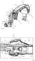
- an inventive motor vehicle handle device 1 is shown in a perspective plan view, whereas the figure 2 shows a perspective rear view of the motor vehicle handle device 1 .
- the motor vehicle handle device 1 has a handle body 2 and a handle panel 3 which is detachably fastened to the handle body 2 .
- the handle body 2 has a first longitudinal end 4 and a second longitudinal end 5 .
- a bearing arm 6 which has a free end 7 protrudes from the first longitudinal end 4 .
- the free end 7 of the support arm 6 is designed for the pivotable support of the handle body 2 .
- the support arm 6 is angled.
- the support arm 6 is essentially L-shaped, although other shapes are also conceivable.
- a grip hook 8 extends from the second longitudinal end 5 of the grip body 2 and can be coupled to a locking device of a motor vehicle, for example, so that pivoting the grip body 2 can unlock a motor vehicle door, for example.
- a recess 9 is formed in the handle body 2, through which light can be emitted to illuminate a recessed grip and/or to illuminate the area in front of a motor vehicle door.
- the Recess 9 is formed on a side of the handle body 2 facing away from the handle panel 3 .
- FIG. 1 shows a front view of the motor vehicle handle device 1, the handle panel 3 not being shown in this view and thus being removed from the handle body 2.
- FIG. 4 Finally, an individual representation of the motor vehicle handle device 1 is shown in a perspective view.
- the handle body 2 also has a receiving space 10 .
- the receiving space 10 is formed between the first longitudinal end 4 and the second longitudinal end 5 and extends between the first longitudinal end 4 and the second longitudinal end 5.
- the motor vehicle handle assembly 1 has a light module 11 with a light exit area 12, from which light is emitted for illumination.
- the light exit area 12 of the light module 11 is, for example, from figure 8 visible, in which the light module 11 is shown in a perspective view.
- the light module 11 is housed within the receiving space 10 in such a way that the light exit area 12 is arranged in the recess 9 of the handle body 2 .
- the motor vehicle handle device 1 also has an electronic module 14 which is housed within the receiving space 10 of the handle body 2 and which is designed, for example, to check access by an authorized user.
- the electronics module 14 can be equipped with a sensor and/or communication device, for example, in order to be able to communicate with an ID transmitter. From the figure 3 shows that the light module 11 is arranged lying between the electronics module 14 and the support arm 6 within the receiving space 10 and is fixed in the receiving space 10 .
- the cables 15 belonging to the motor vehicle handle device 1 can also be seen, which are used to transmit energy and/or information and connect a connector plug 16 attached to the free end 7 of the support arm 6 both to the light module 11 and to the electronic module 14, see above that a supply of the light module 11 and the electronic module 14 via the cable 15 and the connector plug 16 is ensured.
- the light module 11 is supplied with energy to generate light and the electronic module 14 is supplied with energy for operation, whereas information which the electronic module 14 generates, for example in the course of checking access for an authorized user, is sent via the cable 15 and the connector plug 16 to a control unit of a motor vehicle and can be further processed there.
- figure 7 shows the wiring described above, with the exception of the electronic module 14, where a connector 19 (see for example figure 7 ) connects the cable 15 to the electronic module 14.
- a connector 19 see for example figure 7
- a single cable can alternatively be provided instead of a plurality of cables 15, as long as this one cable is designed to be suitable for the transmission of energy and information.
- a plug connector 19 there is also an open cable end or an overmolded contact and is connected to the electronics module 14 .
- the motor vehicle handle device 1 has a cable routing element 17 which consists of the Figures 3 to 7 , 9 and 10 is evident.
- the cable routing element 17 is fixed to the light module 11 and extends at least in sections into the support arm 6 .
- a channel 18 is formed, which differs from that Receiving space 10 extends to the free end 7 of the support arm 6 (see for example Figures 3 and 5 ).
- the channel 18 is formed as a slot-shaped recess 24 with a bottom wall 25 in the support arm 6, such as that of figure 6 can be seen.
- the cables 15 are arranged to run in the channel 18, with the cables 15 running from the connector plug 16 through the channel 18 via the light module 11 to the electronic module 14 (see, for example, Figures 3 , 5 , 6 and 10 ).
- figure 5 a side perspective view of the motor vehicle handle device 1 according to the invention
- the figures 6 and 10 Show details of the arrangement of light module 11, electronic module 14, cable 15 and cable routing element 17.
- the cable guide element 17 guides the cable(s) 15 in sections and aligns the cable(s) 15 in such a way that the cable(s) 15 run lying within the channel 18 or that the cable(s) 15 are housed in the recess 24 and are protected while running extend within the recess 24 up to the connector plug 16.
- the light module 11 is shown in a perspective view.
- the light module 11 is shown without the cable routing element 17 attached to it.
- the light module 11 has a base body 20 from which the light exit area 12 arranged in the recess 9 of the handle body 2 extends. Furthermore is off figure 8 to recognize that the light module 11 is formed with a step 21, on which the cable guide element 17 is fixed at least in sections.
- the step 21 formed on the base body 20 of the light module 11 is formed on a side of the light module 11 facing away from the light exit region 12 .
- the cable routing element 17 fixed to the step 21 of the light module 11 extends transversely to the longitudinal extent 22 of the light module 11.
- the cable guide element 17 is designed to be elongate and has a longitudinal extent 23 which is greater than its height and width. Furthermore, the cable guide element 17 is formed with a first leg 26, a second leg 27 and a connecting leg 28 (see, for example, Figures 9 and 10 ).
- the connecting leg 28 connects the first leg 26 and the second leg 27 to one another (see FIG Figures 9 and 10 ).
- the second leg 27 extends parallel to the first leg 26, although a non-parallel extension of the first leg 26 to the second leg 27 is also conceivable.
- the cables 15 are arranged to run between the bottom wall 25 of the slot-shaped recess 24 in the support arm 6 and the connecting leg 28 .
- the first leg 26 has a longitudinal extension 29 which is greater than a longitudinal extension 30 of the second leg 27 (see FIG Figures 9 and 10 ).
- the first leg 26 is fixed to the light module 11 , a gap 32 being formed between the light module 11 and a free end 31 of the second leg 27 .
- the first leg 26 of the cable routing element 17 is arranged and fixed at least in sections on the step 21 of the base body 20 of the light module 11 .
- the cable routing element 17 is fixed to the base body 20 of the light module 11 .
- the cable routing element 17 is fixed at least in sections on the step 21 of the light module 11 .
- the cable routing element 17 is molded onto the base body 20, with an injection molding process being used for the one-piece unit made up of light module 11 and cable routing element 17, in which the cable routing element 17 and the light module 11 are produced in one piece as a single injection molded part are.
- At least for the A transparent material 33 can be used in the light exit area 12, which can be implemented by means of multi-component injection molding, so that a first material component, i.e. a transparent material 33, is used at least for the light exit area 12 of the light module 11 and for the cable routing element 17 and, if necessary, for a second material component is used for the remaining area of the light module 11 .
Landscapes
- Engineering & Computer Science (AREA)
- Mechanical Engineering (AREA)
- Lock And Its Accessories (AREA)
- Lighting Device Outwards From Vehicle And Optical Signal (AREA)
Abstract
Description
- Die Erfindung richtet sich auf eine Kraftfahrzeug-Griffeinrichtung, aufweisend einen Griffkörper mit einem ersten Längsende, einem zweiten Längsende, wenigstens einer Ausnehmung und einem Aufnahmeraum, welcher an dem Griffkörper zwischen dem ersten Längsende und dem zweiten Längsende ausgebildet ist, ein Lichtmodul, welches innerhalb des Aufnahmeraumes untergebracht angeordnet ist und welches wenigstens einen in der wenigstens einen Ausnehmung angeordneten Lichtaustrittsbereich aufweist, und wenigstens ein Kabel, welches zumindest zur Übertragung von Energie dienend ausgebildet ist und welches mit dem Lichtmodul verbunden ist, wobei von dem ersten Längsende ein Lagerungsarm mit einem freien Ende, welches zur schwenkbaren Lagerung des Griffkörpers ausgebildet ist, abragt.
- Eine Kraftfahrzeug-Griffeinrichtung der vorstehend beschriebenen Art ist zum Beispiel aus der
DE 10 2013 112 835 A1 bekannt. Diese bekannte Kraftfahrzeug-Griffeinrichtung weist einen Griffkörper auf, welcher einen Aufnahmeraum und ein oder zwei Ausnehmungen aufweist. Innerhalb des Aufnahmeraumes ist im montierten Zustand ein Lichtmodul untergebracht, wobei das Lichtmodul einen Lichtaustrittsbereich oder zwei Lichtaustrittsbereiche aufweist. Ein jeweiliger Lichtaustrittsbereich ist dabei in der zugeordneten Ausnehmung des Griffkörpers angeordnet, so dass der Lichtaustrittsbereich des Lichtmoduls entweder für eine Griffmulden-Beleuchtung und/oder für eine Vorfeld-Beleuchtung dient. Von dem Griffkörper ragt ein Lagerungsarm ab, über welchen der Griffkörper zum Beispiel an einer Kraftfahrzeugtür schwenkbar gelagert ist. Zur Versorgung des Lichtmoduls mit Energie ist wenigstens ein Kabel vorgesehen, welches sich von dem in dem Aufnahmeraum untergebrachten Lichtmodul bis zu dem freien Ende des Lagerungsarms erstreckt und dort mit einem Stecker verbunden ist. Dabei erstreckt sich das wenigstens eine Kabel entlang des Lagerungsarms. Bei der Montage des Lagerungsarms an beispielsweise einem an einer Kraftfahrzeugtür befestigten Griffträger besteht die Gefahr, dass das wenigstens eine Kabel gequetscht und beschädigt wird, wobei diese Gefahr für das wenigstens eine Kabel bereits beim Einsetzen des Lichtmoduls in den Aufnahmeraum des Griffkörpers besteht. Für eine derartige Kraftfahrzeug-Griffeinrichtung ist es bekannt, mehrere Kabel mit einem Gewebeband zu ummanteln und dadurch zu bündeln, um diese vor einer Beschädigung zu schützen und zu führen. Allerdings stellt die Ummantelung des wenigstens einen Kabels einen zusätzlichen und aufwendigen Arbeitsschritt vor dem eigentlichen Zusammenbau des Griffkörpers und der eigentlichen Montage des Griffkörpers an dem Griffträger dar, was sich nachteilig auf den zeitlichen Arbeitsaufwand sowie auf die Zusatzmaterialkosten und folglich auf die Gesamtkosten der Kraftfahrzeug-Griffeinrichtung auswirkt. - Der Erfindung liegt die Aufgabe zugrunde eine Lösung zu schaffen, die auf konstruktiv einfache Weise eine verbesserte Kraftfahrzeug-Griffeinrichtung bereitstellt, durch welche die vorstehend genannten Nachteile vermieden werden und durch welche eine komfortable und gefahrlose Montage sowohl des Lichtmoduls an dem Griffkörper als auch der gesamten Kraftfahrzeug-Griffeinrichtung an einem Kraftfahrzeug möglich ist.
- Bei einer Kraftfahrzeug-Griffeinrichtung der eingangs beschriebenen Art wird die Aufgabe erfindungsgemäß dadurch gelöst, dass in dem Lagerungsarm ein Kanal ausgebildet ist, welcher sich von dem Aufnahmeraum bis hin zu dem freien Ende des Lagerungsarms erstreckt und in welchem das wenigstens eine Kabel verlaufend angeordnet ist, und dass ein Kabelführungselement an dem Lichtmodul festgelegt ist und sich zumindest abschnittsweise in den Lagerungsarm hinein erstreckt.
- Vorteilhafte und zweckmäßige Ausgestaltungen und Weiterbildungen der Erfindung ergeben sich aus den Unteransprüchen.
- Durch die Erfindung wird eine Kraftfahrzeug-Griffeinrichtung zur Verfügung gestellt, welche sich durch eine einfache, aber höchst effiziente Konstruktion auszeichnet. Dadurch, dass in dem Lagerungsarm ein sich von dem Aufnahmeraum bis hin zu dem freien Ende des Lagerungsarms erstreckender Kanal ausgebildet ist, ist an dem Lagerungsarm ein Raum geschaffen, in welchem das wenigstens eine Kabel geschützt liegend angeordnet ist. Um zu verhindern, dass das wenigstens eine Kabel aus dem Kanal des Lagerungsarms hervorsteht, ist erfindungsgemäß zusätzlich das Kabelführungselement vorgesehen, welches sich abschnittsweise in den Lagerungsarm hinein erstreckt. Dabei ist es von besonderem Vorteil, dass das Kabelführungselement an dem Lichtmodul festgelegt ist. Denn dadurch muss das Kabelführungselement nicht separat an dem Griffkörper befestigt werden, was zu einem zusätzlichen Montage-Schritt führen würde. Vielmehr wird bei Montage des Lichtmoduls an dem Griffkörper gleichzeitig auch das Kabelführungselement vorteilhafterweise an dem Griffkörper in einem einzigen Montage-Schritt befestigt, so dass kein zusätzlicher Aufwand besteht. Dabei kann im Sinne der Erfindung ein "Festlegen" des Kabelführungselements an dem Lichtmodul eine lösbare Verbindung sein, mit welcher das Kabelführungselement beispielsweise über eine Schraubverbindung an dem Lichtmodul lösbar befestigt ist. Denkbar ist aber auch im Sinne der Erfindung, dass das "Festlegen" des Kabelführungselements an dem Lichtmodul eine einstückige Verbindung meint, bei welcher zum Beispiel das Kabelführungselement und das Lichtmodul als ein einziges Spritzguss-Teil einstückig hergestellt sind, so dass das Kabelführungselement an dem Lichtmodul angespritzt angeordnet ist und mit dem Lichtmodul ein einteiliges Bauteil darstellt. Durch die erfindungsgemäße Ausgestaltung des an dem Lichtmodul festgelegten Kabelführungselements ist auf wirksame Weise ein Einquetschen oder eine Beschädigung des wenigstens einen Kabels beim Einsetzen des Lichtmoduls mitsamt dem Kabelführungselement in den Griffkörper sowie bei Montage des Griffkörpers an einem Kraftfahrzeug verhindert, so dass insgesamt durch die Erfindung die Montage erleichtert wird.
- Die Erfindung sieht in Ausgestaltung vor, dass das Kabelführungselement über eine lösbare Verbindung an dem Lichtmodul befestigt ist. Dabei kann die lösbare Verbindung zum Beispiel eine Schraubverbindung sein, wodurch es möglich ist, verschiedene Kabelführungselemente mit unterschiedlichen Lichtmodulen lösbar zu verbinden, so dass die Einheit aus Lichtmodul und Kabelführungselement für unterschiedliche Ausführungen von Griffkörpern von Kraftfahrzeug-Griffeinrichtungen nach Art eines Baukastenprinzips anpassbar ist.
- Alternativ dazu ist in einer anderen Ausgestaltung der Erfindung vorgesehen, dass das Lichtmodul einen Grundkörper aufweist, an welchem das Kabelführungselement angespritzt angeformt ist. Hierzu kann ein Spritzguss-Verfahren verwendet werden, bei welchem das Kabelführungselement und das Lichtmodul als ein einziges Spritzguss-Teil einstückig hergestellt sind, so dass das Kabelführungselement an dem Lichtmodul angespritzt ist.
- Eine weitere Alternative besteht in Ausgestaltung der Erfindung darin, dass das Lichtmodul einen Grundkörper aufweist, welcher zumindest abschnittsweise im Bereich des wenigstens einen Lichtaustrittsbereichs von einem transparenten Material ausgebildet ist. Das transparente Material stellt dabei einen Schutz für das Lichtmodul vor Beschädigung dar, wobei die Transparenz des Materials sicherstellt, dass das Licht zur Mulden- und/oder Vorfeld-Beleuchtung aus dem Lichtaustrittsbereich auch tatsächlich austreten kann. Dabei kann die einstückige Einheit aus Lichtmodul und Kabelführungselement mittels Mehrkomponenten-Spritzgießens hergestellt sein, wobei zum Beispiel das Lichtmodul aus einer ersten Komponente spritzgegossen ist und anschließend das Kabelführungselement aus einer zweiten Komponente spritzgegossen ist. Mit anderen Worten sieht die Erfindung hierbei vor, dass das Lichtmodul einen Grundkörper aufweist, welcher eine Schutzhülle ausbildet, wobei die Schutzhülle zumindest abschnittsweise im Bereich des wenigstens einen Lichtaustrittsbereichs von einem transparenten Material ausgebildet ist. Denkbar ist es auch, dass das transparente Material nicht vollständig, sondern nur abschnittweise an das Lichtmodul angespritzt ist.
- Zur sichern Unterbringung und Führung des wenigstens einen Kabels sieht die Erfindung in Ausgestaltung vor, dass der Kanal als schlitzförmige Aussparung mit einer Bodenwandung in dem Lagerungsarm ausgebildet ist, wobei das Kabelführungselement mit einem ersten Schenkel, einem zweiten Schenkel, welcher sich parallel zu dem ersten Schenkel erstrecken kann, und einem Verbindungsschenkel, welcher den ersten Schenkel und den zweiten Schenkel miteinander verbindet, ausgebildet ist, und wobei das wenigstens eine Kabel zwischen der Bodenwandung und dem Verbindungsschenkel verlaufend angeordnet ist. Insbesondere ist das wenigstens eine Kabel zwischen dem Verbindungsschenkel, dem ersten Schenkel, dem zweiten Schenkel und der Bodenwandung angeordnet, so dass das wenigstens eine Kabel sicher innerhalb der schlitzförmigen Aussparung des Lagerungsarms angeordnet ist und ein Quetschen des wenigstens einen Kabels bei Montage der Kraftfahrzeug-Griffeinrichtung sicher verhindert ist.
- Um eine derartige Anordnung des wenigstens einen Kabels zu realisieren, sieht die Erfindung in weiterer Ausgestaltung vor, dass im Querschnitt betrachtet der erste Schenkel eine Längserstreckung aufweist, welche größer ist als eine Längserstreckung des zweiten Schenkels, wobei der erste Schenkel an dem Lichtmodul festgelegt ist und wobei zwischen dem Lichtmodul und einem freien Ende des zweiten Schenkels ein Spalt ausgebildet ist. Durch diesen Spalt kann dann beispielsweise das wenigstens eine Kabel aus dem von dem Kabelführungselement und der Bodenwandung gebildeten Raum entnommen werden, sollte dies einmal zu Wartungs- oder Reparaturzwecken erforderlich werden.
- Für eine stabile und genau definierte Festlegung sowie Positionierung des Kabelführungselements an dem Lichtmodul sieht die Erfindung in weiterer Ausgestaltung vor, dass das Lichtmodul mit einer Stufe ausgebildet ist, wobei der erste Schenkel zumindest abschnittsweise an der Stufe festgelegt ist.
- Um den Bedienkomfort für einen Benutzer der erfindungsgemäßen Kraftfahrzeug-Griffeinrichtung zu erhöhen, ist in einer weiteren Ausgestaltung der Erfindung vorgesehen, dass ein Elektronikmodul innerhalb des Aufnahmeraumes untergebracht angeordnet ist, wobei das wenigstens eine Kabel zusätzlich zur Übertragung von Informationen dienend ausgebildet ist und mit dem Elektronikmodul verbunden ist. Das Elektronikmodul kann dabei beispielsweise zu einer Überprüfung eines Zugangs für einen berechtigen und einen ID-Geber verwendenden Benutzer dienen, wie es aus dem Stand der Technik bekannt ist, so dass an dieser Stelle nicht weiter auf diese Funktionalität eingegangen werden braucht.
- Erfindungsgemäß ist ferner vorgesehen, dass das Lichtmodul zwischen dem Elektronikmodul und dem Lagerungsarm liegend innerhalb des Aufnahmeraumes angeordnet ist. Diese Anordnung ist beispielsweise für eine Muldenbeleuchtung besonders günstig, da das Lichtmodul damit die geringste Entfernung zum Schwenkpunkt des Griffkörpers in Form des freien Endes des Lagerungsarms aufweist, so dass bei ausgeschwenktem Griffkörper die Intensität des von dem Lichtmodul ausgestrahlten Lichts nicht speziell angepasst werden muss, da sich die Lage des Lichtmoduls in Bezug auf die Griffmulde nur unwesentlich bei Verschwenkung der des Griffkörpers der Kraftfahrzeug-Griffeinrichtung ändert.
- Schließlich ist es im Hinblick auf einen einfachen und unkomplizierten Austausch von Lichtmodul und/oder Elektronikmodul von besonderem Vorteil, wenn eine den Aufnahmeraum verschließend ausgebbildete Griffblende an dem Griffkörper lösbar befestigt ist. Da die Griffblende ein Design-Element darstellt, kann damit ferner ein universell verwendbarer Griffkörper mit einer für ein entsprechend angepasstes Kraftfahrzeug ausgebildeten Griffblende kombiniert werden.
- Es versteht sich, dass die vorstehend genannten und nachstehenden noch zu erläuternden Merkmale nicht nur in der jeweils angegebenen Kombination, sondern auch in anderen Kombinationen oder in Alleinstellung verwendbar sind, ohne den Rahmen der vorliegenden Erfindung zu verlassen. Der Rahmen der Erfindung ist nur durch die Ansprüche definiert.
- Weitere Einzelheiten, Merkmale und Vorteile des Gegenstandes der Erfindung ergeben sich aus der nachfolgenden Beschreibung im Zusammenhang mit der Zeichnung, in der ein beispielhaftes und bevorzugtes Ausführungsbeispiel der Erfindung dargestellt ist.
- In der Zeichnung zeigt:
-
Figur 1 eine perspektivische Vorderansicht auf eine erfindungsgemäße Kraftfahrzeug-Griffeinrichtung, -
Figur 2 eine perspektivische Rückansicht auf die erfindungsgemäße Kraftfahrzeug-Griffeinrichtung, -
Figur 3 eine weitere perspektivische Vorderansicht auf die erfindungsgemäße Kraftfahrzeug-Griffeinrichtung, bei welcher eine Griffblende nicht dargestellt ist, -
Figur 4 eine perspektivische Einzelteildarstellung der erfindungsgemäßen Kraftfahrzeug-Griffeinrichtung, -
Figur 5 eine weitere Perspektivansicht auf die inFigur 3 gezeigte Kraftfahrzeug-Griffeinrichtung, -
Figur 6 eine perspektivische Detailansicht auf einen Griffkörper der erfindungsgemäßen Kraftfahrzeug-Griffeinrichtung, wobei an dem Griffkörper ein Lichtmodul und ein Kabelführungselement angeordnet sind, -
Figur 7 eine perspektivische Ansicht auf einen Anschlussstecker, das Lichtmodul und einen Steckverbinder, wobei Kabel den Anschlussstecker mit dem Lichtmodul und dem Steckverbinder verbinden, -
Figur 8 eine perspektivische Ansicht auf das Lichtmodul der erfindungsgemäßen Kraftfahrzeug-Griffeinrichtung, -
Figur 9 eine perspektivische Ansicht auf das Lichtmodul und das daran festgelegte Kabelführungselement, und -
Figur 10 eine perspektivische und zu Teil geschnittene Detailansicht auf einen Kanal, in welchem das - In
Figur 1 ist eine erfindungsgemäße Kraftfahrzeug-Griffeinrichtung 1 in einer perspektivischen Draufsicht dargestellt, wohingegen dieFigur 2 eine perspektivische Rückansicht auf die Kraftfahrzeug-Griffeinrichtung 1 zeigt. Mit Bezug auf dieFiguren 1 und 2 weist die Kraftfahrzeug-Griffeinrichtung 1 einen Griffkörper 2 und eine lösbar an dem Griffkörper 2 befestigte Griffblende 3 auf. Dabei weist der Griffkörper 2 ein erstes Längsende 4 und ein zweites Längsende 5 auf. Wie denFiguren 1 und 2 ferner zu entnehmen ist, ragt von dem ersten Längsende 4 ein Lagerungsarm 6 ab, welcher ein freies Ende 7 aufweist. Das freie Ende 7 des Lagerungsarms 6 ist zur schwenkbaren Lagerung des Griffkörpers 2 ausgebildet. Insbesondere ist der Lagerungsarm 6 abgewinkelt ausgebildet. In dem dargestellten Ausführungsbeispiel ist der Lagerungsarm 6 im Wesentlichen L-förmig ausgebildet, wobei auch andere Formen denkbar sind. Von dem zweiten Längsende 5 des Griffkörpers 2 erstreckt sich ein Griffhaken 8, welcher beispielsweise mit einer Schließeinrichtung eines Kraftfahrzeugs gekoppelt werden kann, so dass eine Verschwenkung des Griffkörpers 2 zum Beispiel eine Entriegelung einer Kraftfahrzeugtür bewirken kann. Wie aus derFigur 2 ersichtlich ist, ist in dem Griffkörper 2 eine Ausnehmung 9 ausgebildet, durch welche Licht zur Beleuchtung einer Griffmulde und/oder zur Vorfeldbeleuchtung einer Kraftfahrzeugtür ausgestrahlt werden kann. Daher ist die Ausnehmung 9 auf einer der Griffblende 3 abgewandten Seite des Griffkörpers 2 ausgebildet. - Die
Figur 3 zeigt eine Vorderansicht auf die Kraftfahrzeug-Griffeinrichtung 1, wobei in dieser Darstellung die Griffblende 3 nicht dargestellt und somit von dem Griffkörper 2 entfernt ist. InFigur 4 ist schließlich eine Einzelteildarstellung der Kraftfahrzeug-Griffeinrichtung 1 in einer Perspektivansicht gezeigt. Wie denFiguren 3 und 4 zu entnehmen ist, weist der Griffkörper 2 ferner einen Aufnahmeraum 10 auf. Der Aufnahmeraum 10 ist dabei zwischen dem ersten Längsende 4 und dem zweiten Längsende 5 ausgebildet und erstreckt sich zwischen dem ersten Längsende 4 und dem zweiten Längsende 5. Ferner weist die Kraftfahrzeug-Griffeinrichtung 1 ein Lichtmodul 11 mit einem Lichtaustrittsbereich 12 auf, von welchem aus Licht zur Beleuchtung ausgestrahlt wird. Der Lichtaustrittsbereich 12 des Lichtmoduls 11 ist zum Beispiel aus derFigur 8 ersichtlich, in welcher das Lichtmodul 11 in einer Perspektivansicht dargestellt ist. Das Lichtmodul 11 ist innerhalb des Aufnahmeraumes 10 derart untergebracht angeordnet, dass der Lichtaustrittsbereich 12 in der Ausnehmung 9 des Griffkörpers 2 angeordnet ist. In dem in sämtlichen Figuren dargestellten Ausführungsbeispiel weist die Kraftfahrzeug-Griffeinrichtung 1 ferner ein Elektronikmodul 14 auf, welches innerhalb des Aufnahmeraumes 10 des Griffkörpers 2 untergebracht angeordnet ist und welches beispielsweise zur Überprüfung eines Zugangs eines berechtigten Benutzers ausgebildet ist. Dabei kann das Elektronikmodul 14 zum Beispiel mit einem Sensor und/oder Kommunikationseinrichtung ausgestattet sein, um mit einem ID-Geber kommunizieren zu können. Aus derFigur 3 geht hervor, dass das Lichtmodul 11 zwischen dem Elektronikmodul 14 und dem Lagerungsarm 6 liegend innerhalb des Aufnahmeraumes 10 angeordnet und in dem Aufnahmeraum 10 fixiert ist. Die lösbar an dem Griffkörper 2 befestigte Griffblende 3 verschließt dabei im zusammengebauten Zustand der Kraftfahrzeug-Griffeinrichtung 1 den Aufnahmeraum 10 und deckt damit das Lichtmodul 11 und das Elektronikmodul 14 schützend ab. - Aus den
Figuren 3 und 4 sind ferner zur Kraftfahrzeug-Griffeinrichtung 1 gehörende Kabel 15 ersichtlich, welche zur Übertragung von Energie und/oder von Informationen dienen und einen an dem freien Ende 7 des Lagerungsarms 6 angebrachten Anschlussstecker 16 sowohl mit dem Lichtmodul 11 als auch mit dem Elektronikmodul 14 verbinden, so dass eine Versorgung des Lichtmoduls 11 und des Elektronikmoduls 14 über die Kabel 15 und den Anschlussstecker 16 sichergestellt ist. Dabei wird das Lichtmodul 11 zur Erzeugung von Licht und das Elektronikmodul 14 zum Betrieb mit Energie versorgt, wohingegen Informationen, welche das Elektronikmodul 14 beispielsweise im Zuge einer Überprüfung eines Zugangs für einen berechtigten Benutzer generiert, über die Kabel 15 und den Anschlussstecker 16 zu einer Steuerungseinheit eines Kraftfahrzeugs geleitet und dort weiterverarbeitet werden können. InFigur 7 ist die vorstehend beschriebene Verkabelung mit Ausnahme des Elektronikmoduls 14 gezeigt, wobei ein Steckverbinder 19 (siehe zum BeispielFigur 7 ) die Kabel 15 mit dem Elektronikmodul 14 verbindet. Es versteht sich, dass abweichend von dem konkreten Ausführungsbeispiel statt mehrerer Kabel 15 alternativ auch nur ein einziges Kabel vorgesehen sein kann, solange dieses eine Kabel zur Übertragung von Energie und von Informationen geeignet ausgebildet ist. Ebenso ist es denkbar, dass statt eines Steckverbinders 19 auch ein offenes Kabelende oder ein umspritzter Kontakt vorliegt und mit dem Elektronikmodul 14 verbunden ist. - Erfindungsgemäß weist die Kraftfahrzeug-Griffeinrichtung 1 ein Kabelführungselement 17 auf, welches aus den
Figuren 3 bis 7 ,9 und 10 ersichtlich ist. Das Kabelführungselement 17 ist an dem Lichtmodul 11 festgelegt und erstreckt sich zumindest abschnittweise in den Lagerungsarm 6 hinein. In dem Lagerungsarm 6 ist ein Kanal 18 ausgebildet, welcher sich von dem Aufnahmeraum 10 bis hin zu dem freien Ende 7 des Lagerungsarms 6 erstreckt (siehe zum BeispielFiguren 3 und5 ). Der Kanal 18 ist als eine schlitzförmige Aussparung 24 mit einer Bodenwandung 25 in dem Lagerungsarm 6 ausgebildet, wie es beispielsweise derFigur 6 zu entnehmen ist. Dabei sind in dem Kanal 18 die Kabel 15 verlaufend angeordnet, wobei die Kabel 15 von dem Anschlussstecker 16 durch den Kanal 18 über das Lichtmodul 11 bis zu dem Elektronikmodul 14 verlaufen (siehe beispielsweiseFiguren 3 ,5 ,6 und10 ). Hierbei zeigtFigur 5 eine seitliche Perspektivansicht auf die erfindungsgemäße Kraftfahrzeug-Griffeinrichtung 1, wohingegen dieFiguren 6 und10 Details zu der Anordnung von Lichtmodul 11, Elektronikmodul 14, Kabel 15 und Kabelführungselement 17 zeigen. Das Kabelführungselement 17 führt abschnittsweise das/die Kabel 15 und richtet das/die Kabel 15 derart aus, dass das/die Kabel 15 innerhalb des Kanals 18 liegend verlaufen bzw. dass das/die Kabel 15 in der Aussparung 24 geschützt verlaufend untergebracht sind und sich innerhalb der Aussparung 24 bis hin zu dem Anschlussstecker 16 erstrecken. - In
Figur 8 ist das Lichtmodul 11 in einer perspektivischen Ansicht dargestellt. Das Lichtmodul 11 ohne das daran festgelegte Kabelführungselement 17 dargestellt. Das Lichtmodul 11 weist einen Grundkörper 20 auf, von welchem aus sich der in der Ausnehmung 9 des Griffkörpers 2 angeordnete Lichtaustrittsbereich 12 erstreckt. Ferner ist ausFigur 8 zu erkennen, dass das Lichtmodul 11 mit einer Stufe 21 ausgebildet ist, auf welcher das Kabelführungselement 17 zumindest abschnittsweise festgelegt ist. Die an dem Grundkörper 20 des Lichtmoduls 11 ausgebildete Stufe 21 ist auf einer dem Lichtaustrittsbereich 12 abgewandten Seite des Lichtmoduls 11 ausgebildet. Dabei erstreckt sich das an der Stufe 21 des Lichtmoduls 11 festgelegte Kabelführungselement 17 quer zu der Längserstreckung 22 des Lichtmoduls 11. - Wie beispielsweise der
Figur 10 zu entnehmen ist, ist das Kabelführungselement 17 länglich verlaufend ausgebildet und weist eine Längserstreckung 23 auf, die größer als seine Höhe und Breite ist. Ferner ist das Kabelführungselement 17 mit einem ersten Schenkel 26, einem zweiten Schenkel 27 und einem Verbindungsschenkel 28 ausgebildet (siehe zum BeispielFiguren 9 und 10 ). Der Verbindungsschenkel 28 verbindet den ersten Schenkel 26 und den zweiten Schenkel 27 miteinander (sieheFiguren 9 und 10 ). Bei dem dargestellten Ausführungsbeispiel erstreckt sich der zweite Schenkel 27 parallel zu dem ersten Schenkel 26, wobei aber auch eine nicht parallele Erstreckung des ersten Schenkels 26 zu dem zweiten Schenkel 27 denkbar ist. Wie ferner dieFiguren 6 und10 zeigen, sind die Kabel 15 zwischen der Bodenwandung 25 der schlitzförmigen Aussparung 24 in dem Lagerungsarm 6 und dem Verbindungsschenkel 28 verlaufend angeordnet. Der erste Schenkel 26 weist im Querschnitt betrachtet eine Längserstreckung 29 aufweist, welche größer ist als eine Längserstreckung 30 des zweiten Schenkels 27 (sieheFiguren 9 und 10 ). Wie insbesondere aus derFigur 9 ersichtlich ist, ist der erste Schenkel 26 an dem Lichtmodul 11 festgelegt, wobei zwischen dem Lichtmodul 11 und einem freien Ende 31 des zweiten Schenkels 27 ein Spalt 32 ausgebildet ist. Genauer gesagt ist der erste Schenkel 26 des Kabelführungselements 17 zumindest abschnittsweise an der Stufe 21 des Grundkörpers 20 des Lichtmoduls 11 angeordnet und festgelegt. - Mit Bezug auf
Figur 9 ist schließlich gezeigt, dass das Kabelführungselement 17 an dem Grundkörper 20 des Lichtmoduls 11 festgelegt ist. Insbesondere ist das Kabelführungselement 17 zumindest abschnittsweise an der Stufe 21 des Lichtmoduls 11 festgelegt. Entsprechend dem dargestellten Ausführungsbeispiel ist das Kabelführungselement 17 an dem Grundkörper 20 angespritzt angeformt, wobei für die einstückige Einheit aus Lichtmodul 11 und Kabelführungselement 17 ein Spritzguss-Verfahren verwendet wird, bei welchem das Kabelführungselement 17 und das Lichtmodul 11 als ein einziges Spritzguss-Teil einstückig hergestellt sind. Dabei muss zumindest für den Lichtaustrittsbereich 12 ein transparentes Material 33 verwendet werden, was mittels eines Mehrkomponenten-Spritzgießens realisiert werden kann, so dass zumindest für den Lichtaustrittsbereich 12 des Lichtmoduls 11 eine erste Materialkomponente, d.h. ein transparentes Material 33, verwendet wird und für das Kabelführungselement 17 und ggf. für den übrigen Bereich des Lichtmoduls 11 eine zweite Materialkomponente verwendet wird. - Die beschriebene Erfindung ist selbstverständlich nicht auf die beschriebene und dargestellte Ausführungsform beschränkt. Es ist ersichtlich, dass an der in der Zeichnung dargestellten Ausführungsform zahlreiche, dem Fachmann entsprechend der beabsichtigten Anwendung naheliegende Abänderungen vorgenommen werden können, ohne dass dadurch der Bereich der Erfindung verlassen wird. Zur Erfindung gehört alles dasjenige, was in der Beschreibung enthalten und/oder in der Zeichnung dargestellt ist, einschließlich dessen, was abweichend von dem konkreten Ausführungsbeispiel für den Fachmann naheliegt.
Claims (10)
- Kraftfahrzeug-Griffeinrichtung (1), aufweisend einen Griffkörper (2) mit einem ersten Längsende (4), einem zweiten Längsende (5), wenigstens einer Ausnehmung (9) und einem Aufnahmeraum (10), welcher an dem Griffkörper (2) zwischen dem ersten Längsende (4) und dem zweiten Längsende (5) ausgebildet ist, ein Lichtmodul (11), welches innerhalb des Aufnahmeraumes (10) untergebracht angeordnet ist und welches wenigstens einen in der wenigstens einen Ausnehmung (9) angeordneten Lichtaustrittsbereich (12) aufweist, und wenigstens ein Kabel (15), welches zumindest zur Übertragung von Energie dienend ausgebildet ist und welches mit dem Lichtmodul (11) verbunden ist, wobei von dem ersten Längsende (4) ein Lagerungsarm (6) mit einem freien Ende (7), welches zur schwenkbaren Lagerung des Griffkörpers (2) ausgebildet ist, abragt,
dadurch gekennzeichnet,
dass in dem Lagerungsarm (6) ein Kanal (18) ausgebildet ist, welcher sich von dem Aufnahmeraum (10) bis hin zu dem freien Ende (7) des Lagerungsarms (6) erstreckt und in welchem das wenigstens eine Kabel (15) verlaufend angeordnet ist, und
dass ein Kabelführungselement (17) an dem Lichtmodul (11) festgelegt ist und sich zumindest abschnittsweise in den Lagerungsarm (6) hinein erstreckt. - Kraftfahrzeug-Griffeinrichtung (1) nach Anspruch 1,
dadurch gekennzeichnet, dass das Lichtmodul (11) einen Grundkörper (20) aufweist, an welchem das Kabelführungselement (17) angespritzt angeformt ist. - Kraftfahrzeug-Griffeinrichtung (1) nach Anspruch 1 oder 2, dadurch gekennzeichnet, dass das Lichtmodul (11) einen Grundkörper (20) aufweist, welcher zumindest abschnittsweise im Bereich des wenigstens einen Lichtaustrittsbereichs (12) von einem transparenten Material (33) ausgebildet ist.
- Kraftfahrzeug-Griffeinrichtung (1) nach Anspruch 1 oder 2, dadurch gekennzeichnet, dass das Lichtmodul (11) einen Grundkörper (20) aufweist, welcher eine Schutzhülle (34) ausbildet, wobei die Schutzhülle (34) zumindest abschnittsweise im Bereich des wenigstens einen Lichtaustrittsbereichs (12) von einem transparenten Material (33) ausgebildet ist.
- Kraftfahrzeug-Griffeinrichtung (1) nach einem der vorhergehenden Ansprüche, dadurch gekennzeichnet, dass der Kanal (18) des Lagerungsarms (6) als schlitzförmige Aussparung (24) mit einer Bodenwandung (25) in dem Lagerungsarm (6) ausgebildet ist, wobei das Kabelführungselement (17) mit einem ersten Schenkel (26), einem zweiten Schenkel (27) und einem Verbindungsschenkel (28), welcher den ersten Schenkel (26) und den zweiten Schenkel (27) miteinander verbindet, ausgebildet ist, und wobei das wenigstens eine Kabel (15) zwischen der Bodenwandung (25) und dem Verbindungsschenkel (28) verlaufend angeordnet ist.
- Kraftfahrzeug-Griffeinrichtung (1) nach Anspruch 5, dadurch gekennzeichnet, dass im Querschnitt betrachtet der erste Schenkel (26) eine Längserstreckung (29) aufweist, welche größer ist als eine Längserstreckung (30) des zweiten Schenkels (27), wobei der erste Schenkel (26) an dem Lichtmodul (11) festgelegt ist und wobei zwischen dem Lichtmodul (11) und einem freien Ende (31) des zweiten Schenkels (27) ein Spalt (32) ausgebildet ist.
- Kraftfahrzeug-Griffeinrichtung (1) nach Anspruch 6, dadurch gekennzeichnet, dass das Lichtmodul (11) mit einer Stufe (21) ausgebildet ist, wobei der erste Schenkel (26) zumindest abschnittsweise an der Stufe (21) festgelegt ist.
- Kraftfahrzeug-Griffeinrichtung (1) nach einem der vorhergehenden Ansprüche, dadurch gekennzeichnet, dass ein Elektronikmodul (14) innerhalb des Aufnahmeraumes (10) untergebracht angeordnet ist, wobei das wenigstens eine Kabel (15) zusätzlich zur Übertragung von Informationen dienend ausgebildet ist und mit dem Elektronikmodul (14) verbunden ist.
- Kraftfahrzeug-Griffeinrichtung (1) nach Anspruch 8, dadurch gekennzeichnet, dass das Lichtmodul (11) zwischen dem Elektronikmodul (14) und dem Lagerungsarm (6) liegend innerhalb des Aufnahmeraumes (10) angeordnet ist.
- Kraftfahrzeug-Griffeinrichtung (1) nach einem der vorhergehenden Ansprüche, dadurch gekennzeichnet, dass eine den Aufnahmeraum (10) verschließend ausgebbildete Griffblende (3) an dem Griffkörper (2) lösbar befestigt ist.
Applications Claiming Priority (1)
| Application Number | Priority Date | Filing Date | Title |
|---|---|---|---|
| DE102020123473.2A DE102020123473A1 (de) | 2020-09-09 | 2020-09-09 | Kraftfahrzeug-Griffeinrichtung |
Publications (2)
| Publication Number | Publication Date |
|---|---|
| EP3967551A1 true EP3967551A1 (de) | 2022-03-16 |
| EP3967551B1 EP3967551B1 (de) | 2024-02-21 |
Family
ID=76374874
Family Applications (1)
| Application Number | Title | Priority Date | Filing Date |
|---|---|---|---|
| EP21176901.3A Active EP3967551B1 (de) | 2020-09-09 | 2021-05-31 | Kraftfahrzeug-griffeinrichtung |
Country Status (2)
| Country | Link |
|---|---|
| EP (1) | EP3967551B1 (de) |
| DE (1) | DE102020123473A1 (de) |
Citations (8)
| Publication number | Priority date | Publication date | Assignee | Title |
|---|---|---|---|---|
| US20030122556A1 (en) * | 2001-11-20 | 2003-07-03 | Masahiko Sueyoshi | Vehicle door handle system |
| US20050231364A1 (en) * | 2004-03-30 | 2005-10-20 | Kabushiki Kaisha Honda Lock | Vehicle door handle device |
| US20090147528A1 (en) * | 2007-12-05 | 2009-06-11 | Ming-Cheng Wang | Lighting handle of car |
| US20120106182A1 (en) * | 2010-10-28 | 2012-05-03 | AISIN Technical Center of America, Inc. | Lit door handle for a vehicle |
| US20120170298A1 (en) * | 2010-12-30 | 2012-07-05 | Huf Hulsbeck & Furst Gmbh & Co. Kg | External assembly component for a vehicle having a light module |
| DE102013112835A1 (de) | 2013-11-20 | 2015-05-21 | Huf Hülsbeck & Fürst Gmbh & Co. Kg | Lichtmodul für eine Griffeinrichtung |
| JP2016199918A (ja) * | 2015-04-10 | 2016-12-01 | 株式会社アルファ | 車両のハンドル装置 |
| FR3022869B1 (fr) * | 2014-06-30 | 2018-03-30 | Akwel Vigo Spain Sl | Piece d’equipement pour vehicule automobile et procede de fabrication d’une telle piece d’equipement |
-
2020
- 2020-09-09 DE DE102020123473.2A patent/DE102020123473A1/de active Pending
-
2021
- 2021-05-31 EP EP21176901.3A patent/EP3967551B1/de active Active
Patent Citations (8)
| Publication number | Priority date | Publication date | Assignee | Title |
|---|---|---|---|---|
| US20030122556A1 (en) * | 2001-11-20 | 2003-07-03 | Masahiko Sueyoshi | Vehicle door handle system |
| US20050231364A1 (en) * | 2004-03-30 | 2005-10-20 | Kabushiki Kaisha Honda Lock | Vehicle door handle device |
| US20090147528A1 (en) * | 2007-12-05 | 2009-06-11 | Ming-Cheng Wang | Lighting handle of car |
| US20120106182A1 (en) * | 2010-10-28 | 2012-05-03 | AISIN Technical Center of America, Inc. | Lit door handle for a vehicle |
| US20120170298A1 (en) * | 2010-12-30 | 2012-07-05 | Huf Hulsbeck & Furst Gmbh & Co. Kg | External assembly component for a vehicle having a light module |
| DE102013112835A1 (de) | 2013-11-20 | 2015-05-21 | Huf Hülsbeck & Fürst Gmbh & Co. Kg | Lichtmodul für eine Griffeinrichtung |
| FR3022869B1 (fr) * | 2014-06-30 | 2018-03-30 | Akwel Vigo Spain Sl | Piece d’equipement pour vehicule automobile et procede de fabrication d’une telle piece d’equipement |
| JP2016199918A (ja) * | 2015-04-10 | 2016-12-01 | 株式会社アルファ | 車両のハンドル装置 |
Also Published As
| Publication number | Publication date |
|---|---|
| EP3967551B1 (de) | 2024-02-21 |
| DE102020123473A1 (de) | 2022-03-10 |
Similar Documents
| Publication | Publication Date | Title |
|---|---|---|
| EP3194210B1 (de) | Beleuchtungsvorrichtung mit darin verriegelbarer lichtleiteranordnung | |
| EP2904982B1 (de) | Elektrochirurgisches Gerät mit einem Buchseneinsatz, Set mit einem Entnahmewerkzeug und Verfahren zum entnehmen eines Buchseneinsatzes | |
| DE102005016043B4 (de) | Aufbau zum Montieren eines Akkukastens auf einem elektrischen Fahrrad | |
| DE112007003732B4 (de) | Schneid- oder Sägemaschine | |
| DE102011111399B4 (de) | Glasfaser-Netzverteiler und Haltevorrichtung hierfür | |
| EP1574776B1 (de) | Schutzeinrichtung, insbesondere Lichtgitter | |
| EP3467240B1 (de) | Verfahren zum endpositionierten montieren eines türgriffträgers und türgriffträgerbefestigungsset | |
| EP3967551B1 (de) | Kraftfahrzeug-griffeinrichtung | |
| EP1107172B1 (de) | Kartenlesevorrichtung mit beleuchtetem Einsteckschlitz | |
| EP0365698A1 (de) | Statusanzeigeeinrichtung | |
| DE19934229A1 (de) | Türsturzanordnung für eine automatische Schiebetüre | |
| EP2106001A1 (de) | Steckdosenanordnung | |
| EP2236239B1 (de) | Abdeckvorrichtung für ein mittels eines Lasers zu bearbeitendes Werkstück | |
| DE102011107610A1 (de) | Leitungshalter zur Befestigung an einem Träger einer Flugzeugstruktur | |
| DE1806718A1 (de) | Instrumententafel in einem Kraftwagen | |
| DE102009008909B4 (de) | Sensoreinheit mit einem Schutzprofil | |
| DE3403092C2 (de) | Hobelmaschine | |
| DE102022203083A1 (de) | Schutzabdeckung zum Schutz eines Hochvoltkabel eines elektrischen Fahrzeugtraktionsantriebs | |
| DE3800728A1 (de) | Einschub | |
| DE202019002833U1 (de) | Kabeldurchführung für einen Steuerungsschrank | |
| EP4297003B1 (de) | Rettungszeichenleuchte mit zusätzlicher rettungswegbeleuchtung | |
| DE102023204785B3 (de) | Antrieb für einen Flügel | |
| EP0959371A2 (de) | Lichtgitterprofil | |
| DE3040319C2 (de) | Baugruppe mit Frontplatte | |
| DE102007048998B4 (de) | Bausatz für eine Schließvorrichtung |
Legal Events
| Date | Code | Title | Description |
|---|---|---|---|
| PUAI | Public reference made under article 153(3) epc to a published international application that has entered the european phase |
Free format text: ORIGINAL CODE: 0009012 |
|
| STAA | Information on the status of an ep patent application or granted ep patent |
Free format text: STATUS: THE APPLICATION HAS BEEN PUBLISHED |
|
| AK | Designated contracting states |
Kind code of ref document: A1 Designated state(s): AL AT BE BG CH CY CZ DE DK EE ES FI FR GB GR HR HU IE IS IT LI LT LU LV MC MK MT NL NO PL PT RO RS SE SI SK SM TR |
|
| STAA | Information on the status of an ep patent application or granted ep patent |
Free format text: STATUS: REQUEST FOR EXAMINATION WAS MADE |
|
| 17P | Request for examination filed |
Effective date: 20220916 |
|
| RBV | Designated contracting states (corrected) |
Designated state(s): AL AT BE BG CH CY CZ DE DK EE ES FI FR GB GR HR HU IE IS IT LI LT LU LV MC MK MT NL NO PL PT RO RS SE SI SK SM TR |
|
| STAA | Information on the status of an ep patent application or granted ep patent |
Free format text: STATUS: EXAMINATION IS IN PROGRESS |
|
| 17Q | First examination report despatched |
Effective date: 20230203 |
|
| GRAP | Despatch of communication of intention to grant a patent |
Free format text: ORIGINAL CODE: EPIDOSNIGR1 |
|
| STAA | Information on the status of an ep patent application or granted ep patent |
Free format text: STATUS: GRANT OF PATENT IS INTENDED |
|
| INTG | Intention to grant announced |
Effective date: 20231009 |
|
| GRAS | Grant fee paid |
Free format text: ORIGINAL CODE: EPIDOSNIGR3 |
|
| GRAA | (expected) grant |
Free format text: ORIGINAL CODE: 0009210 |
|
| STAA | Information on the status of an ep patent application or granted ep patent |
Free format text: STATUS: THE PATENT HAS BEEN GRANTED |
|
| AK | Designated contracting states |
Kind code of ref document: B1 Designated state(s): AL AT BE BG CH CY CZ DE DK EE ES FI FR GB GR HR HU IE IS IT LI LT LU LV MC MK MT NL NO PL PT RO RS SE SI SK SM TR |
|
| REG | Reference to a national code |
Ref country code: GB Ref legal event code: FG4D Free format text: NOT ENGLISH |
|
| P01 | Opt-out of the competence of the unified patent court (upc) registered |
Effective date: 20240124 |
|
| REG | Reference to a national code |
Ref country code: CH Ref legal event code: EP |
|
| REG | Reference to a national code |
Ref country code: IE Ref legal event code: FG4D Free format text: LANGUAGE OF EP DOCUMENT: GERMAN |
|
| REG | Reference to a national code |
Ref country code: DE Ref legal event code: R096 Ref document number: 502021002731 Country of ref document: DE |
|
| REG | Reference to a national code |
Ref country code: LT Ref legal event code: MG9D |
|
| REG | Reference to a national code |
Ref country code: NL Ref legal event code: MP Effective date: 20240221 |
|
| PG25 | Lapsed in a contracting state [announced via postgrant information from national office to epo] |
Ref country code: IS Free format text: LAPSE BECAUSE OF FAILURE TO SUBMIT A TRANSLATION OF THE DESCRIPTION OR TO PAY THE FEE WITHIN THE PRESCRIBED TIME-LIMIT Effective date: 20240621 |
|
| PG25 | Lapsed in a contracting state [announced via postgrant information from national office to epo] |
Ref country code: LT Free format text: LAPSE BECAUSE OF FAILURE TO SUBMIT A TRANSLATION OF THE DESCRIPTION OR TO PAY THE FEE WITHIN THE PRESCRIBED TIME-LIMIT Effective date: 20240221 |
|
| PG25 | Lapsed in a contracting state [announced via postgrant information from national office to epo] |
Ref country code: GR Free format text: LAPSE BECAUSE OF FAILURE TO SUBMIT A TRANSLATION OF THE DESCRIPTION OR TO PAY THE FEE WITHIN THE PRESCRIBED TIME-LIMIT Effective date: 20240522 |
|
| PG25 | Lapsed in a contracting state [announced via postgrant information from national office to epo] |
Ref country code: HR Free format text: LAPSE BECAUSE OF FAILURE TO SUBMIT A TRANSLATION OF THE DESCRIPTION OR TO PAY THE FEE WITHIN THE PRESCRIBED TIME-LIMIT Effective date: 20240221 Ref country code: NL Free format text: LAPSE BECAUSE OF FAILURE TO SUBMIT A TRANSLATION OF THE DESCRIPTION OR TO PAY THE FEE WITHIN THE PRESCRIBED TIME-LIMIT Effective date: 20240221 Ref country code: RS Free format text: LAPSE BECAUSE OF FAILURE TO SUBMIT A TRANSLATION OF THE DESCRIPTION OR TO PAY THE FEE WITHIN THE PRESCRIBED TIME-LIMIT Effective date: 20240521 |
|
| PG25 | Lapsed in a contracting state [announced via postgrant information from national office to epo] |
Ref country code: ES Free format text: LAPSE BECAUSE OF FAILURE TO SUBMIT A TRANSLATION OF THE DESCRIPTION OR TO PAY THE FEE WITHIN THE PRESCRIBED TIME-LIMIT Effective date: 20240221 |
|
| PG25 | Lapsed in a contracting state [announced via postgrant information from national office to epo] |
Ref country code: RS Free format text: LAPSE BECAUSE OF FAILURE TO SUBMIT A TRANSLATION OF THE DESCRIPTION OR TO PAY THE FEE WITHIN THE PRESCRIBED TIME-LIMIT Effective date: 20240521 Ref country code: NO Free format text: LAPSE BECAUSE OF FAILURE TO SUBMIT A TRANSLATION OF THE DESCRIPTION OR TO PAY THE FEE WITHIN THE PRESCRIBED TIME-LIMIT Effective date: 20240521 Ref country code: NL Free format text: LAPSE BECAUSE OF FAILURE TO SUBMIT A TRANSLATION OF THE DESCRIPTION OR TO PAY THE FEE WITHIN THE PRESCRIBED TIME-LIMIT Effective date: 20240221 Ref country code: LT Free format text: LAPSE BECAUSE OF FAILURE TO SUBMIT A TRANSLATION OF THE DESCRIPTION OR TO PAY THE FEE WITHIN THE PRESCRIBED TIME-LIMIT Effective date: 20240221 Ref country code: IS Free format text: LAPSE BECAUSE OF FAILURE TO SUBMIT A TRANSLATION OF THE DESCRIPTION OR TO PAY THE FEE WITHIN THE PRESCRIBED TIME-LIMIT Effective date: 20240621 Ref country code: HR Free format text: LAPSE BECAUSE OF FAILURE TO SUBMIT A TRANSLATION OF THE DESCRIPTION OR TO PAY THE FEE WITHIN THE PRESCRIBED TIME-LIMIT Effective date: 20240221 Ref country code: GR Free format text: LAPSE BECAUSE OF FAILURE TO SUBMIT A TRANSLATION OF THE DESCRIPTION OR TO PAY THE FEE WITHIN THE PRESCRIBED TIME-LIMIT Effective date: 20240522 Ref country code: FI Free format text: LAPSE BECAUSE OF FAILURE TO SUBMIT A TRANSLATION OF THE DESCRIPTION OR TO PAY THE FEE WITHIN THE PRESCRIBED TIME-LIMIT Effective date: 20240221 Ref country code: ES Free format text: LAPSE BECAUSE OF FAILURE TO SUBMIT A TRANSLATION OF THE DESCRIPTION OR TO PAY THE FEE WITHIN THE PRESCRIBED TIME-LIMIT Effective date: 20240221 Ref country code: BG Free format text: LAPSE BECAUSE OF FAILURE TO SUBMIT A TRANSLATION OF THE DESCRIPTION OR TO PAY THE FEE WITHIN THE PRESCRIBED TIME-LIMIT Effective date: 20240221 |
|
| PG25 | Lapsed in a contracting state [announced via postgrant information from national office to epo] |
Ref country code: PL Free format text: LAPSE BECAUSE OF FAILURE TO SUBMIT A TRANSLATION OF THE DESCRIPTION OR TO PAY THE FEE WITHIN THE PRESCRIBED TIME-LIMIT Effective date: 20240221 Ref country code: PT Free format text: LAPSE BECAUSE OF FAILURE TO SUBMIT A TRANSLATION OF THE DESCRIPTION OR TO PAY THE FEE WITHIN THE PRESCRIBED TIME-LIMIT Effective date: 20240621 |
|
| PG25 | Lapsed in a contracting state [announced via postgrant information from national office to epo] |
Ref country code: SE Free format text: LAPSE BECAUSE OF FAILURE TO SUBMIT A TRANSLATION OF THE DESCRIPTION OR TO PAY THE FEE WITHIN THE PRESCRIBED TIME-LIMIT Effective date: 20240221 Ref country code: PT Free format text: LAPSE BECAUSE OF FAILURE TO SUBMIT A TRANSLATION OF THE DESCRIPTION OR TO PAY THE FEE WITHIN THE PRESCRIBED TIME-LIMIT Effective date: 20240621 Ref country code: PL Free format text: LAPSE BECAUSE OF FAILURE TO SUBMIT A TRANSLATION OF THE DESCRIPTION OR TO PAY THE FEE WITHIN THE PRESCRIBED TIME-LIMIT Effective date: 20240221 Ref country code: LV Free format text: LAPSE BECAUSE OF FAILURE TO SUBMIT A TRANSLATION OF THE DESCRIPTION OR TO PAY THE FEE WITHIN THE PRESCRIBED TIME-LIMIT Effective date: 20240221 |
|
| PG25 | Lapsed in a contracting state [announced via postgrant information from national office to epo] |
Ref country code: DK Free format text: LAPSE BECAUSE OF FAILURE TO SUBMIT A TRANSLATION OF THE DESCRIPTION OR TO PAY THE FEE WITHIN THE PRESCRIBED TIME-LIMIT Effective date: 20240221 |
|
| PG25 | Lapsed in a contracting state [announced via postgrant information from national office to epo] |
Ref country code: SM Free format text: LAPSE BECAUSE OF FAILURE TO SUBMIT A TRANSLATION OF THE DESCRIPTION OR TO PAY THE FEE WITHIN THE PRESCRIBED TIME-LIMIT Effective date: 20240221 |
|
| PG25 | Lapsed in a contracting state [announced via postgrant information from national office to epo] |
Ref country code: CZ Free format text: LAPSE BECAUSE OF FAILURE TO SUBMIT A TRANSLATION OF THE DESCRIPTION OR TO PAY THE FEE WITHIN THE PRESCRIBED TIME-LIMIT Effective date: 20240221 Ref country code: EE Free format text: LAPSE BECAUSE OF FAILURE TO SUBMIT A TRANSLATION OF THE DESCRIPTION OR TO PAY THE FEE WITHIN THE PRESCRIBED TIME-LIMIT Effective date: 20240221 |
|
| PG25 | Lapsed in a contracting state [announced via postgrant information from national office to epo] |
Ref country code: SK Free format text: LAPSE BECAUSE OF FAILURE TO SUBMIT A TRANSLATION OF THE DESCRIPTION OR TO PAY THE FEE WITHIN THE PRESCRIBED TIME-LIMIT Effective date: 20240221 |
|
| PG25 | Lapsed in a contracting state [announced via postgrant information from national office to epo] |
Ref country code: SM Free format text: LAPSE BECAUSE OF FAILURE TO SUBMIT A TRANSLATION OF THE DESCRIPTION OR TO PAY THE FEE WITHIN THE PRESCRIBED TIME-LIMIT Effective date: 20240221 Ref country code: SK Free format text: LAPSE BECAUSE OF FAILURE TO SUBMIT A TRANSLATION OF THE DESCRIPTION OR TO PAY THE FEE WITHIN THE PRESCRIBED TIME-LIMIT Effective date: 20240221 Ref country code: RO Free format text: LAPSE BECAUSE OF FAILURE TO SUBMIT A TRANSLATION OF THE DESCRIPTION OR TO PAY THE FEE WITHIN THE PRESCRIBED TIME-LIMIT Effective date: 20240221 Ref country code: EE Free format text: LAPSE BECAUSE OF FAILURE TO SUBMIT A TRANSLATION OF THE DESCRIPTION OR TO PAY THE FEE WITHIN THE PRESCRIBED TIME-LIMIT Effective date: 20240221 Ref country code: DK Free format text: LAPSE BECAUSE OF FAILURE TO SUBMIT A TRANSLATION OF THE DESCRIPTION OR TO PAY THE FEE WITHIN THE PRESCRIBED TIME-LIMIT Effective date: 20240221 Ref country code: CZ Free format text: LAPSE BECAUSE OF FAILURE TO SUBMIT A TRANSLATION OF THE DESCRIPTION OR TO PAY THE FEE WITHIN THE PRESCRIBED TIME-LIMIT Effective date: 20240221 |
|
| REG | Reference to a national code |
Ref country code: DE Ref legal event code: R097 Ref document number: 502021002731 Country of ref document: DE |
|
| PG25 | Lapsed in a contracting state [announced via postgrant information from national office to epo] |
Ref country code: IT Free format text: LAPSE BECAUSE OF FAILURE TO SUBMIT A TRANSLATION OF THE DESCRIPTION OR TO PAY THE FEE WITHIN THE PRESCRIBED TIME-LIMIT Effective date: 20240221 |
|
| PLBE | No opposition filed within time limit |
Free format text: ORIGINAL CODE: 0009261 |
|
| STAA | Information on the status of an ep patent application or granted ep patent |
Free format text: STATUS: NO OPPOSITION FILED WITHIN TIME LIMIT |
|
| REG | Reference to a national code |
Ref country code: CH Ref legal event code: PL |
|
| PG25 | Lapsed in a contracting state [announced via postgrant information from national office to epo] |
Ref country code: IT Free format text: LAPSE BECAUSE OF FAILURE TO SUBMIT A TRANSLATION OF THE DESCRIPTION OR TO PAY THE FEE WITHIN THE PRESCRIBED TIME-LIMIT Effective date: 20240221 |
|
| PG25 | Lapsed in a contracting state [announced via postgrant information from national office to epo] |
Ref country code: MC Free format text: LAPSE BECAUSE OF FAILURE TO SUBMIT A TRANSLATION OF THE DESCRIPTION OR TO PAY THE FEE WITHIN THE PRESCRIBED TIME-LIMIT Effective date: 20240221 |
|
| PG25 | Lapsed in a contracting state [announced via postgrant information from national office to epo] |
Ref country code: LU Free format text: LAPSE BECAUSE OF NON-PAYMENT OF DUE FEES Effective date: 20240531 |
|
| 26N | No opposition filed |
Effective date: 20241122 |
|
| PG25 | Lapsed in a contracting state [announced via postgrant information from national office to epo] |
Ref country code: MC Free format text: LAPSE BECAUSE OF FAILURE TO SUBMIT A TRANSLATION OF THE DESCRIPTION OR TO PAY THE FEE WITHIN THE PRESCRIBED TIME-LIMIT Effective date: 20240221 Ref country code: LU Free format text: LAPSE BECAUSE OF NON-PAYMENT OF DUE FEES Effective date: 20240531 Ref country code: CH Free format text: LAPSE BECAUSE OF NON-PAYMENT OF DUE FEES Effective date: 20240531 |
|
| REG | Reference to a national code |
Ref country code: BE Ref legal event code: MM Effective date: 20240531 |
|
| PG25 | Lapsed in a contracting state [announced via postgrant information from national office to epo] |
Ref country code: IE Free format text: LAPSE BECAUSE OF NON-PAYMENT OF DUE FEES Effective date: 20240531 |
|
| PG25 | Lapsed in a contracting state [announced via postgrant information from national office to epo] |
Ref country code: SI Free format text: LAPSE BECAUSE OF FAILURE TO SUBMIT A TRANSLATION OF THE DESCRIPTION OR TO PAY THE FEE WITHIN THE PRESCRIBED TIME-LIMIT Effective date: 20240221 Ref country code: BE Free format text: LAPSE BECAUSE OF NON-PAYMENT OF DUE FEES Effective date: 20240531 |
|
| PG25 | Lapsed in a contracting state [announced via postgrant information from national office to epo] |
Ref country code: FR Free format text: LAPSE BECAUSE OF NON-PAYMENT OF DUE FEES Effective date: 20240531 |
|
| PGFP | Annual fee paid to national office [announced via postgrant information from national office to epo] |
Ref country code: DE Payment date: 20250531 Year of fee payment: 5 |
|
| PGFP | Annual fee paid to national office [announced via postgrant information from national office to epo] |
Ref country code: AT Payment date: 20250721 Year of fee payment: 5 |
|
| PG25 | Lapsed in a contracting state [announced via postgrant information from national office to epo] |
Ref country code: CY Free format text: LAPSE BECAUSE OF FAILURE TO SUBMIT A TRANSLATION OF THE DESCRIPTION OR TO PAY THE FEE WITHIN THE PRESCRIBED TIME-LIMIT; INVALID AB INITIO Effective date: 20210531 |
|
| GBPC | Gb: european patent ceased through non-payment of renewal fee |
Effective date: 20250531 |
|
| PG25 | Lapsed in a contracting state [announced via postgrant information from national office to epo] |
Ref country code: HU Free format text: LAPSE BECAUSE OF FAILURE TO SUBMIT A TRANSLATION OF THE DESCRIPTION OR TO PAY THE FEE WITHIN THE PRESCRIBED TIME-LIMIT; INVALID AB INITIO Effective date: 20210531 |
|
| PG25 | Lapsed in a contracting state [announced via postgrant information from national office to epo] |
Ref country code: GB Free format text: LAPSE BECAUSE OF NON-PAYMENT OF DUE FEES Effective date: 20250531 |