EP3967472A1 - Procédé et dispositif d'emballage des pièces moulées par injection - Google Patents
Procédé et dispositif d'emballage des pièces moulées par injection Download PDFInfo
- Publication number
- EP3967472A1 EP3967472A1 EP20195861.8A EP20195861A EP3967472A1 EP 3967472 A1 EP3967472 A1 EP 3967472A1 EP 20195861 A EP20195861 A EP 20195861A EP 3967472 A1 EP3967472 A1 EP 3967472A1
- Authority
- EP
- European Patent Office
- Prior art keywords
- injection molded
- molded parts
- packaging
- workpiece carrier
- injection
- Prior art date
- Legal status (The legal status is an assumption and is not a legal conclusion. Google has not performed a legal analysis and makes no representation as to the accuracy of the status listed.)
- Withdrawn
Links
- 238000002347 injection Methods 0.000 title claims abstract description 160
- 239000007924 injection Substances 0.000 title claims abstract description 160
- 238000004806 packaging method and process Methods 0.000 title claims abstract description 140
- 238000000034 method Methods 0.000 title claims abstract description 43
- 238000001746 injection moulding Methods 0.000 claims abstract description 49
- 239000000969 carrier Substances 0.000 claims description 22
- 238000004519 manufacturing process Methods 0.000 claims description 13
- 238000003780 insertion Methods 0.000 claims description 9
- 230000037431 insertion Effects 0.000 claims description 9
- 230000005540 biological transmission Effects 0.000 claims description 7
- 238000012360 testing method Methods 0.000 claims description 6
- 230000007246 mechanism Effects 0.000 claims description 5
- 230000004888 barrier function Effects 0.000 claims description 4
- 230000003287 optical effect Effects 0.000 claims description 4
- 238000007789 sealing Methods 0.000 claims description 2
- 238000000151 deposition Methods 0.000 abstract description 2
- 238000003908 quality control method Methods 0.000 description 7
- 230000008569 process Effects 0.000 description 4
- 230000008901 benefit Effects 0.000 description 3
- 230000002950 deficient Effects 0.000 description 3
- 230000008859 change Effects 0.000 description 2
- 238000009826 distribution Methods 0.000 description 2
- 230000005484 gravity Effects 0.000 description 2
- 238000012858 packaging process Methods 0.000 description 2
- 239000002699 waste material Substances 0.000 description 2
- 108010001267 Protein Subunits Proteins 0.000 description 1
- 230000001419 dependent effect Effects 0.000 description 1
- 238000007689 inspection Methods 0.000 description 1
- 239000000463 material Substances 0.000 description 1
- 238000003825 pressing Methods 0.000 description 1
- 238000000275 quality assurance Methods 0.000 description 1
- 239000002994 raw material Substances 0.000 description 1
- 230000000284 resting effect Effects 0.000 description 1
- 238000009517 secondary packaging Methods 0.000 description 1
- 230000006641 stabilisation Effects 0.000 description 1
- 238000011105 stabilization Methods 0.000 description 1
Images


Classifications
-
- B—PERFORMING OPERATIONS; TRANSPORTING
- B29—WORKING OF PLASTICS; WORKING OF SUBSTANCES IN A PLASTIC STATE IN GENERAL
- B29C—SHAPING OR JOINING OF PLASTICS; SHAPING OF MATERIAL IN A PLASTIC STATE, NOT OTHERWISE PROVIDED FOR; AFTER-TREATMENT OF THE SHAPED PRODUCTS, e.g. REPAIRING
- B29C45/00—Injection moulding, i.e. forcing the required volume of moulding material through a nozzle into a closed mould; Apparatus therefor
- B29C45/17—Component parts, details or accessories; Auxiliary operations
- B29C45/1769—Handling of moulded articles or runners, e.g. sorting, stacking, grinding of runners
-
- B—PERFORMING OPERATIONS; TRANSPORTING
- B01—PHYSICAL OR CHEMICAL PROCESSES OR APPARATUS IN GENERAL
- B01L—CHEMICAL OR PHYSICAL LABORATORY APPARATUS FOR GENERAL USE
- B01L3/00—Containers or dishes for laboratory use, e.g. laboratory glassware; Droppers
- B01L3/02—Burettes; Pipettes
- B01L3/0275—Interchangeable or disposable dispensing tips
-
- B—PERFORMING OPERATIONS; TRANSPORTING
- B29—WORKING OF PLASTICS; WORKING OF SUBSTANCES IN A PLASTIC STATE IN GENERAL
- B29C—SHAPING OR JOINING OF PLASTICS; SHAPING OF MATERIAL IN A PLASTIC STATE, NOT OTHERWISE PROVIDED FOR; AFTER-TREATMENT OF THE SHAPED PRODUCTS, e.g. REPAIRING
- B29C45/00—Injection moulding, i.e. forcing the required volume of moulding material through a nozzle into a closed mould; Apparatus therefor
- B29C45/17—Component parts, details or accessories; Auxiliary operations
- B29C45/40—Removing or ejecting moulded articles
- B29C45/42—Removing or ejecting moulded articles using means movable from outside the mould between mould parts, e.g. robots
- B29C45/4225—Take-off members or carriers for the moulded articles, e.g. grippers
-
- B—PERFORMING OPERATIONS; TRANSPORTING
- B01—PHYSICAL OR CHEMICAL PROCESSES OR APPARATUS IN GENERAL
- B01L—CHEMICAL OR PHYSICAL LABORATORY APPARATUS FOR GENERAL USE
- B01L2200/00—Solutions for specific problems relating to chemical or physical laboratory apparatus
- B01L2200/12—Specific details about manufacturing devices
-
- B—PERFORMING OPERATIONS; TRANSPORTING
- B01—PHYSICAL OR CHEMICAL PROCESSES OR APPARATUS IN GENERAL
- B01L—CHEMICAL OR PHYSICAL LABORATORY APPARATUS FOR GENERAL USE
- B01L9/00—Supporting devices; Holding devices
- B01L9/54—Supports specially adapted for pipettes and burettes
- B01L9/543—Supports specially adapted for pipettes and burettes for disposable pipette tips, e.g. racks or cassettes
-
- B—PERFORMING OPERATIONS; TRANSPORTING
- B29—WORKING OF PLASTICS; WORKING OF SUBSTANCES IN A PLASTIC STATE IN GENERAL
- B29C—SHAPING OR JOINING OF PLASTICS; SHAPING OF MATERIAL IN A PLASTIC STATE, NOT OTHERWISE PROVIDED FOR; AFTER-TREATMENT OF THE SHAPED PRODUCTS, e.g. REPAIRING
- B29C45/00—Injection moulding, i.e. forcing the required volume of moulding material through a nozzle into a closed mould; Apparatus therefor
- B29C45/17—Component parts, details or accessories; Auxiliary operations
- B29C45/40—Removing or ejecting moulded articles
- B29C45/42—Removing or ejecting moulded articles using means movable from outside the mould between mould parts, e.g. robots
- B29C45/4225—Take-off members or carriers for the moulded articles, e.g. grippers
- B29C2045/4233—Take-off members or carriers for the moulded articles, e.g. grippers loading or holding moulded articles in take-off member by fluid ejection
-
- B—PERFORMING OPERATIONS; TRANSPORTING
- B65—CONVEYING; PACKING; STORING; HANDLING THIN OR FILAMENTARY MATERIAL
- B65B—MACHINES, APPARATUS OR DEVICES FOR, OR METHODS OF, PACKAGING ARTICLES OR MATERIALS; UNPACKING
- B65B25/00—Packaging other articles presenting special problems
-
- B—PERFORMING OPERATIONS; TRANSPORTING
- B65—CONVEYING; PACKING; STORING; HANDLING THIN OR FILAMENTARY MATERIAL
- B65B—MACHINES, APPARATUS OR DEVICES FOR, OR METHODS OF, PACKAGING ARTICLES OR MATERIALS; UNPACKING
- B65B5/00—Packaging individual articles in containers or receptacles, e.g. bags, sacks, boxes, cartons, cans, jars
- B65B5/10—Filling containers or receptacles progressively or in stages by introducing successive articles, or layers of articles
Definitions
- the invention relates to a method for transferring injection molded parts, a packaging device, a workpiece carrier and a combination gripper for a packaging device, and an injection molding system comprising a combination gripper.
- the invention further relates to a device for equipping injection molded parts, in particular pipette tips, with filter elements and a device for preparing, filling and forwarding packaging containers.
- the method disclosed therein comprises a method step in which injection molded parts removed from the tool of an injection molding machine are transferred from a ring-shaped arrangement into a row arrangement.
- the transfer station used for this purpose is also used to set the distance between the injection molded parts transferred in a row arrangement according to the receptacles of a workpiece carrier before the injection molded parts can actually be transferred into packaging containers.
- the device used to carry out such a method and the method itself have the disadvantage that the packaging of the injection-molded parts is considerably complicated by the frequent changes in the injection-molded part arrangement described.
- the additionally required process steps and equipment also represent potential sources of interference.
- the injection molded parts can only be randomly tested in this process, which often means that completely filled packaging containers have to be disposed of.
- the object of the present invention is to eliminate these and other disadvantages of the prior art and, in particular, to specify a more advantageous method and a more advantageous packaging device, through which the transfer of injection molded parts, in particular pipette tips, from an injection molding machine into packaging container is realized quickly, efficiently and while avoiding high numbers of rejects.
- the object is achieved by a method for moving injection molded parts, a packaging device, a workpiece carrier and a combination gripper for a packaging device according to the invention, an injection molding system comprising a combination gripper according to the invention, a device for equipping injection molded parts with filter elements, and a device for providing, filling and forwarding of packaging containers according to the independent patent claims. Further advantageous embodiments are the subject matter of the dependent patent claims.
- the object is achieved by a method for converting injection molded parts, in particular pipette tips, from an injection molding machine into packaging containers, the method according to the invention comprising the following steps: Simultaneous removal of K injection molded parts from K cavities of a mold of the injection molding machine in mold order by a removal gripper; Simultaneous depositing of the K injection molded parts in at least one workpiece carrier by the removal gripper; Simultaneously picking up at least one, preferably a plurality of injection molded parts from the at least one workpiece carrier by at least one combination gripper.
- the tool arrangement of the K injection molded parts which is predetermined by the tool of the injection molding machine, is controlled by the removal gripper not changed.
- the at least one combination gripper separates the respectively received injection molded parts when filling the packaging container.
- K is a natural number that is greater than or equal to 2.
- tool order is understood to mean the arrangement of the cavities producing injection molded parts in the tool of an injection molding machine.
- the method according to the invention enables injection molded parts to be packaged particularly efficiently and securely, since the arrangement of the injection molded parts from the mold of the injection molding machine is maintained until the packaging container is filled. This is made possible in particular by the combination of workpiece carriers according to the invention and combination grippers, as will be explained in more detail below.
- the K injection molded parts of one shot of the injection molding machine are preferably distributed over a plurality of workpiece carriers, preferably an even number of workpiece carriers, with each workpiece carrier receiving a subgroup of U injection molded parts.
- the K injection-molded parts are distributed to a plurality of separate workpiece carriers when they are deposited simultaneously by the removal gripper.
- Each workpiece carrier receives a subgroup of U injection molded parts.
- the at least one combination gripper picks up a subgroup of U injection molded parts from one of the workpiece carriers and separates them when filling the packaging container. After all the injection molded parts of the subgroup U picked up by the combination gripper have been placed in the packaging container or containers, the combination gripper is ready to pick up another subgroup U Injection molded parts from another workpiece carrier ready.
- K is a natural number which is a multiple of U.
- the reliability of the method is increased and, for example, it is also possible for some or all of the workpiece carriers to pass through the various devices of the packaging device according to the invention in a different order. This can increase plant utilization and increase the efficiency of the packaging process.
- the number of workpiece carriers required to accommodate K injection-molded parts preferably corresponds to the number of combination grippers used in the method. This enables the injection molded parts to be transferred particularly quickly into the packaging containers provided for this purpose.
- injection molded parts are filled into a packaging container from certain cavities of the mold of the injection molding machine.
- certain configurations of different injection molded parts can be realized in a packaging container, for example pipette tips of different sizes in a single pipette tip holder designed for this purpose.
- injection molded parts are filled into a packaging container from just one cavity of the tool of the injection molding machine.
- This embodiment of the method achieves cavity-clean filling of the packaging container with injection-molded parts.
- by avoiding the merging of injection molded parts produced in different cavities of an injection mold into one and the same packaging container it is avoided that the occurrence of a Problems relating to the injection molded parts of a specific cavity, complete packaging containers contaminated with faulty injection molded parts and subsequently have to be completely disposed of, as is customary in the prior art.
- each injection-molded part is assigned a cavity number of the injection-molding machine, with the injection-molded parts being placed by the combination gripper, by cavity, in the packaging container.
- a predetermined range of cavity numbers is stored in each workpiece carrier.
- Packaging containers with a range of cavity numbers are assigned to each combination gripper.
- a respective workpiece carrier is fed to that combination gripper whose range of cavity numbers match.
- the deviation of an injection molded part, in particular an elongated injection molded part such as a pipette tip, from a standard is assessed by means of a measuring device.
- the injection molded part to be tested is held and preferably rotated by the combination gripper in order to assess the deviation from the standard.
- a deviation from the norm of the injection molded part is measured as a positional deviation of a predetermined area of the injection molded part from a predefined desired position of the area of the injection molded part.
- the warpage of an injection molded part to be tested is measured by comparison with a previously measured, non-warped injection molded part.
- the measuring device is preferably an optical measuring device, for example a camera.
- an injection molded part deviates from a standard, the injection molded part is warped or the injection molded part deviates from a desired shape.
- the pipette tips picked up by the combination gripper can each be rotated individually about the axis of rotation of the pipette tips, with only one camera being required to assess the straightness of the pipettes, as will be explained in more detail below.
- the individual inspection of each pipette tip also solves the problem of faulty pipette tips getting into the packaging container and pipette tip holders that have already been packed and completely filled having to be disposed of.
- Such pipette tip holders are also known under the term rack .
- defective pipette tips can already be sorted out beforehand, for example by dropping these defective pipette tips into a for Rejects containers provided by the combination gripper. This means that only injection molded parts that meet the quality requirements predefined in each individual case are transferred to the packaging container by the combination gripper or grippers.
- the system can automatically find out, for example via a control device, which cavity is causing problems and then deselect the affected cavity or cavities.
- a deselected cavity is a cavity of the injection molding tool in which, as a result of the cavity deselection, all injection molded parts produced in it are regarded as rejects. Without wanting to be limited to this explanation, it is assumed that the injection molding of this cavity cannot simply be stopped, since the thermal balance of the injection molding tool would otherwise become too confused.
- the detected deviations are registered by a control device and assigned to the cavities of the mold of the injection molding machine. This is possible because the arrangement of the injection molded parts in the workpiece carriers is identical to the arrangement of the injection molded parts in the injection molding tool and because the combination gripper picks up the injection molded parts from the workpiece carrier in this tool order and can feed them individually to a test step. If it is determined that the injection molded parts from a cavity exceed a predefined scrap value, the control device selects the affected cavity and/or interrupts the control device the production of the injection molding machine.
- the plant autonomy can be increased.
- injection molded parts from selected cavities are discarded after injection. In this way, disruptions that would occur more frequently during the sorting and checking of the injection molded parts from the selected cavity can be prevented.
- the injection molded parts from deselected cavities are preferably discarded before the injection molded parts are removed by the removal gripper.
- the removal of these injection molded parts from the stream of manufactured injection molded parts or from the packaging process very quickly after injection molding has the advantage that the downstream equipment of the packaging system is not burdened with defective injection molded parts that represent potential sources of interference, which ultimately increases the reliability of the packaging.
- the object is further achieved by a packaging device, in particular for carrying out a method for converting injection molded parts from an injection molding machine into packaging containers as described here.
- a packaging device comprising a removal gripper with a plurality of grippers for injection molded parts, the grippers being arranged on the removal gripper in accordance with the arrangement of the cavities of a mold of an injection molding machine, ie in mold order.
- a packaging device comprises at least a workpiece carrier, which is designed to simultaneously pick up a plurality of injection molded parts in tool order, and at least one combination gripper, which is designed to simultaneously pick up at least one injection molded part and to separate the picked up injection molded parts into packaging containers.
- the at least one combination gripper is preferably designed to simultaneously pick up a plurality of injection molded parts and to separate the picked up injection molded parts into packaging containers.
- the packaging device also includes a control device.
- the control device has at least one interface for data transfer with at least one device of the packaging device, for example with a measuring device.
- a packaging device of this type enables material and product flows to be divided up and distributed in order to efficiently supply the various devices of the packaging device with injection-molded parts.
- a preferred embodiment of the packaging device according to the invention also comprises at least one measuring device, in particular an optical measuring device, for example a camera, for assessing the distortion of an injection molded part.
- the injection molded part is in particular an elongated injection molded part such as a pipette tip.
- conveyor belts, transport rails or push bars can be provided, as are known from the prior art.
- a workpiece carrier for a packaging device as described here, the workpiece carrier comprising a receiving device fastened on a carrier plate.
- the receiving device has a plurality of receiving openings arranged relative to one another in tool order, into each of which an injection-molded part can be inserted up to a holding end of the injection-molded part.
- Pipette tips generally have an elongate, tubular, slightly conical body which has a pipetting opening at one end and a plug-in opening for plugging onto a receiving cone of a pipetting device at the other end.
- the tubular body In the area of the plug-on opening, the tubular body has a circumferential collar on its lateral surface, which is used to hold the pipette tip on the edge of a receiving opening of the receiving device. The surrounding collar thus represents the holding end of a pipette tip.
- the receiving device of the workpiece carrier according to the invention preferably has a receiving area for holding injection molded parts and a guiding area for reducing the lateral play of injection molded parts in the receiving device.
- the receiving area and the guiding area each have a plurality of receiving openings arranged in tool order with respect to one another.
- the receiving openings of the receiving area and the guiding area are aligned coaxially.
- Such a receiving device makes it possible to align injection molded parts along a predefined preferred direction of the workpiece carrier, for example in the direction of gravity.
- the injection-molded parts are held essentially free of play transversely to their direction of insertion into the receiving device.
- pipette tips can be inserted into the receiving openings of the receiving area with their pipetting opening first and can be held by resting their collar on the edge of the respective receiving opening.
- the diameter of the receiving openings of the guide area and the receiving area and the distance between the guide area and the receiving area are selected such that the pipette tips in the respective receiving openings of the receiving area and the guide area have essentially no play in the transverse direction of the pipette tips.
- This alignment of the injection molded parts in a predefined preferred direction in the workpiece carrier helps to stabilize the injection molded parts in the workpiece carrier and facilitates their testing.
- the carrier device and/or the receiving device of the workpiece carrier according to the invention each have at least one centering means for aligning the carrier device and/or the receiving device.
- the alignment of a number of workpiece carriers relative to one another can be simplified, which also simplifies the alignment of the receiving openings of a number of workpiece carriers in order to achieve the tool arrangement.
- filter elements can be pressed in more securely by centering means on the receiving device of a workpiece carrier according to the invention, which can be brought into operative connection with centering means of a device for equipping pipette tips with filter elements, as will be explained in more detail below.
- the carrier device of the workpiece carrier according to the invention is designed as a body with a base area, a top area and four side areas.
- at least one offset groove is arranged on at least one of the side faces of the carrier device, preferably on two adjacent side faces of the carrier device.
- the offset groove can be used, for example, as a stop groove in order to prevent it from falling off a conveyor belt after a correspondingly designed stop pin engages in the offset groove.
- the arrangement of offset grooves on two adjacent side surfaces ensures that the workpiece carrier does not have to be specially aligned when it is placed on a conveyor belt and/or that one of the offset grooves is available for the described stop function even after a change of direction.
- the workpiece carrier comprises an identification element which encodes the workpiece carrier.
- Each receiving opening of the workpiece carrier particularly preferably comprises an identification element, by means of which each receiving opening is encoded.
- the identification elements are preferably barcodes or RFID chips, since such identification elements can be read particularly quickly and reliably.
- a combination gripper for a packaging device comprising a base body with a plurality of pneumatic tools.
- Each of the pneumatic tools comprises a cylinder with a cylinder interior, a connection for connecting the cylinder interior to a pressure source, a piston movable in the cylinder interior in the longitudinal direction of the cylinder, and a hollow piston rod connected to the piston and guided in the cylinder in a sealing manner.
- each of the pneumatic tools comprises a hollow gripping element arranged at one end of the piston rod outside the cylinder for receiving an injection molded part and a connection for connecting a cavity which is formed jointly by the piston rod and the gripping element to a vacuum source.
- Such a combination gripper is designed for the efficient and safe manipulation of injection molded parts, with each of the pneumatic tools for separating the injection molded parts being able to be controlled or actuated individually.
- the combination gripper according to the invention also has the advantage that it can be attached to a conventional industrial robot without any problems and can therefore be easily moved by it. It is of course also possible that instead of the pneumatic tools, other drives, for example electric drives, are used for raising and lowering the gripping elements, each designed to receive an injection-molded part.
- the gripping elements of the combination gripper according to the invention are preferably designed as push-on elements onto which the pipette tips can be pushed with their respective push-on opening.
- the combination gripper according to the invention preferably also comprises a drive unit and at least one gear mechanism connected to the drive unit for transmitting a rotary movement from the drive unit to the piston rod.
- This enables the injection molded parts to rotate on the combination gripper, which means that checking the straightness of elongated injection molded parts such as pipette tips can be made more efficient, since in this case only one measuring device is required for the comprehensive assessment of straightness. This reduces the complexity of the packaging device and saves costs.
- the transmission is preferably a gear transmission.
- the piston rod comprises an outer sleeve and an inner sleeve, which can be displaced relative to one another in the longitudinal direction.
- the gripping element is arranged on the outer sleeve.
- the outer sleeve has a gear wheel in the circumferential direction, which is or can be brought into operative connection with the gear train.
- the object is further achieved by a device for equipping injection molded parts, in particular pipette tips, with filter elements, in particular for use in a method for converting injection molded parts from an injection molding machine into packaging containers as described here.
- a device for equipping injection molded parts with filter elements comprising a press-in device and a centering device.
- the press-in device comprises a plurality of press-in sleeves arranged relative to one another in tool order, in each of which a press-in mandrel can be moved in the longitudinal direction of the press-in sleeves.
- the centering device comprises a plurality of insertion aids arranged in a tool order with respect to one another, which are used to fix the injection-molded parts in a workpiece carrier and to guide the press-in sleeves into the injection-molded parts.
- the workpiece carrier is a workpiece carrier as described here.
- the centering device further includes a first centering element for centering with a centering means of the workpiece carrier, and a second centering element for centering with a centering means of the press-in device.
- the insertion aids, the press-in sleeves and the injection-molded parts to be fitted are coaxially aligned or can be aligned so that a filter element, which is held on the underside of a press-in mandrel facing the injection-molded parts, moves in a straight line through an insertion aid into the interior of one held in a receiving opening of a workpiece carrier Injection molded part can be pressed.
- the press-in sleeves are arranged on a shell holding plate and the press-in mandrels on a mandrel holding plate, the shell holding plate and the mandrel holding plate being connected to one another via a piston which can be moved in a cylinder. Movement of the piston causes movement of the press-in mandrels in the press-in sleeves.
- Such a device is particularly suitable for equipping pipette tips with filter elements.
- the object is further achieved by a device for providing, filling and forwarding packaging containers in a packaging device, in particular for use in a method for converting injection molded parts from an injection molding machine into packaging containers as described here.
- the object is achieved by a device for providing, filling and forwarding packaging containers in a packaging device, the device having at least one buffer location for empty packaging containers, at least one filling location for filling each packaging container with injection molded parts, and at least one buffer location for filled packaging containers.
- Empty packaging containers can be made available by a first transport device and filled packaging containers can be fed to a downstream section of the packaging device by a second transport device.
- the empty and filled packaging containers can be moved by a third transport device from the at least one buffer location for empty packaging containers via the at least one filling location to the at least one buffer location for filled packaging containers.
- Such a device is particularly suitable for providing, filling and forwarding pipette tip holders in a packaging device for pipette tips.
- the device according to the invention for providing, filling and forwarding packaging containers additionally has a first deflection device, in particular a crash barrier that can be swung out over the first transport device, for deflecting empty packaging containers from the first transport device onto the one from the first transport device seen first buffer space for empty packaging containers.
- the device according to the invention for providing, filling and forwarding packaging containers can have a second deflection device, in particular a crash barrier that can be swung out over the second transport device, for releasing and/or deflecting filled packaging containers from the buffer location for filled packaging containers that is closest to the second transport device to the second transport device.
- the object is further achieved by a system for manufacturing and packaging pipette tips, the system according to the invention comprising at least one combination gripper as described here and/or at least one workpiece carrier as described here and optionally at least one device as described here.
- figure 1 shows a schematic representation of the arrangement of K cavities of an injection mold.
- the injection molded parts for example the pipette tips
- the pipettes could be placed on a common workpiece carrier whose receiving elements for receiving the K injection-molded parts replicated the arrangement of the K injection-molded parts in the injection mold.
- the injection molded parts of a shot would all be moved together in the workpiece carrier to at least one combination gripper.
- the combination gripper or grippers each pick up a sub-unit containing 8 injection-molded parts at the same time, and then clean them into the cavity sorted into packaging containers, as will be described in more detail below.
- the K injection molded parts are preferably divided among several carriers, as this works more reliably.
- figure 2 shows a section of a packaging device 100 according to the invention.
- a removal gripper 4 is shown, which has removed injection molded parts 1 from an injection molding machine 2 in tool order.
- eight workpiece carriers 10 which can be moved by a transport device 40 , are available for receiving the injection-molded parts 1 in tool order.
- the transport device 40 is a transport belt, for example.
- the detail shown also shows measuring devices 30, eight cameras in the present example.
- the workpiece carriers 10 can be moved under the measuring devices 30 by means of the transport device 40 in such a way that one workpiece carrier 10 can be positioned under each measuring device 30 . In this position, the holding end of injection molded parts 1 held in the workpiece carriers 10 can be checked visually (not shown).
- FIG 3 shows a schematic representation of four workpiece carriers, each of which is designed to accommodate a subgroup of U injection molded parts, for example pipette tips.
- the arrangement of the receiving openings for injection molded parts provided on the workpiece carrier side which are numbered from one to thirty-two in the present example, is identical to the arrangement of the cavities in the injection molding tool, so that the injection molded parts can be placed directly from the injection molding tool into the workpiece carrier without adjusting their position.
- FIG 4 is shown schematically how the cavity-clean transfer of pipette tips 1 from receiving openings 13 of a workpiece carrier 10 in packaging containers 3, 3 'takes place.
- a combination gripper according to the invention picks up all eight pipette tips 1 from the receiving openings 13 numbered consecutively "01" to "08" (not shown).
- the pipette tips 1 of the receiving openings "01” and "02" have already passed all previous quality controls (not shown).
- the pipette tip from receiving opening "01” is first checked for straightness in a measuring device 30 and, after passing the test, is placed in the packaging container 3 .
- the pipette tip from the receiving opening "02" in the measuring device 30 is tested and, after passing the test, is not placed in the packaging container 3 but in the packaging container 3'.
- the pipette tip 1 from the receiving opening "08” has passed all previous quality controls (not shown) and is sent to the measuring device 30 along the path marked with arrow C for a further quality control to assess the straightness of the pipette tip.
- the pipette tip 1 from the receiving opening "08” does not pass this quality control because it is warped, ie "crooked", and is subsequently disposed of in a waste container 5 .
- the pipette tip 1 from receiving opening "07" has already failed a previous quality control, which was registered by a control device (not shown). This pipette tip is then disposed of directly in the waste container 5 according to the path marked with arrow D, without first having to assess it using the measuring device 30 . This speeds up the process.
- the measuring device 30 can be, for example, a camera or another optical system which is designed to determine a deviation of the respectively measured pipette tip or pipette tips from a normal state.
- a standard condition is understood to mean a pipette tip that meets the quality criterion examined by the respective measuring device, i.e. is in order.
- the measuring device 30 is a device for checking the straightness of the pipette tips.
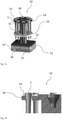
- FIG. 5a shows a workpiece carrier 10 according to the invention for pipette tips 1 in a perspective view.
- the workpiece carrier comprises a carrier device 11 and a receiving device 12 which is fastened to the carrier device 11 in the exemplary embodiment shown.
- the receiving unit 12 can also include a receiving area 14 and a guiding area 15 which each have eight receiving openings 13 for receiving pipette tips 1 here.
- the receiving openings 13 of the receiving area 14 and the guiding area 15 are aligned coaxially so that a pipette tip 1 can be held by a receiving opening 13 of the receiving area 14 and stabilized by the associated receiving opening 13 of the guiding area 15 .
- the stabilization function is essentially achieved by preventing or reducing lateral play of the pipette tip 1 in the receiving openings 13 of the receiving area 14 and the guide area 15 achieved.
- the workpiece carrier 10 also includes a centering means 16 arranged in the area of the carrier unit in the form of a recess and two stepped grooves 17, 17′, which are also arranged in the area of the carrier unit.
- Another centering means 18 is arranged in the area of the receiving area 14, specifically in the form of a recess.
- Figure 5b 1 shows a cross section through the receiving area 14 of the workpiece carrier 10 according to the invention Figure 5a shown, the tubular and cone-like shape of the pipette tips 1 emerging from this view.
- the pipette tips are inserted into the receiving openings 13 with their pipetting opening first (not shown), so that the circumferential collar arranged in the area of the insertion opening of the pipette tips 1 comes to rest on the edge of the receiving opening 13 and the pipette tip 1 is thus held against the direction of gravity.
- FIG 6a shows a combination gripper 20 according to the invention in a perspective view.
- the combination gripper 20 includes a base body 21 which includes a plurality of pneumatic tools 50 .
- the base body 21 has eight pneumatic tools 50.
- the pneumatic tools 50 and in particular the gripping elements 56 designed to hold injection molded parts are arranged on the combination gripper in tool order in order to be able to hold injection molded parts with a corresponding tool order.
- the gripping elements 56 of the combination gripper 20 are designed as conical push-on elements which can each be inserted into a push-on opening of a pipette tip (not shown).
- Each pneumatic tool 50 includes, among other things, a connection 53 for a pressure source and a connection for a vacuum source 57, wherein the pipette tips attached to the push-on elements of the pneumatic tools can be held by applying negative pressure to the push-on element and can be pushed off again by switching off the negative pressure, as will be explained in more detail below.
- FIG Figure 6b 12 shows a cross section through the combination gripper 20.
- each of the eight pneumatic tools 50 having a cylinder 51 with a cylinder interior 52, a port 53 for connecting the cylinder interior 52 to a pressure source, a piston 54 movable in the cylinder interior 52 in the longitudinal direction of the cylinder 51, a piston 54 connected to the piston and in the cylinder 51 sealingly guided hollow piston rod 55, a hollow gripping element 56, and a connection 57 for connecting a cavity 58 formed by the interior of the piston rod 55 and the gripping element 56 to a vacuum source.
- the gripping elements 56 are arranged at one end of the piston rod 55 outside the cylinder 51, namely on the underside of the combination gripper 20 facing the injection molded parts to be picked up.
- FIG 6c a further exemplary embodiment of a combination gripper 20 according to the invention is shown in a cross section.
- the combination gripper 20 includes, in addition to the elements already described for the combination gripper 20 from FIG 55.
- the gripping element 56 arranged on the piston rod 55 is rotated as a result, and consequently also an injection molded part held by a rotating gripping element 56.
- the transmission 60 of the embodiment shown is a gear transmission.
- the piston rod 55 here comprises an outer sleeve 61 and an inner sleeve 62 arranged at least partially in the outer sleeve 61, the outer sleeve 61 and the inner sleeve 62 being mutually displaceable in the longitudinal direction.
- the outer sleeve 61 is connected to the gripping element 56 and has a gear wheel 63 in the circumferential direction. Since the gearwheel 63 is or is brought into an operative connection with the gearwheel mechanism 60 , a rotational movement can be transmitted from the gearwheel mechanism 60 to the outer sleeve 61 of the piston rod 55 .
- FIG 7 an arrangement of a workpiece carrier (10) and a device (70) for equipping pipette tips (1) with filter elements (71) is shown in cross section.
- the device (70) comprises a press-in device (72) and a centering device (73), the press-in device (72) comprising a plurality of press-in sleeves (74) arranged in tool order in relation to one another, in each of which a press-in mandrel (75) runs in the longitudinal direction of the press-in sleeves (74). is movable.
- the centering device (73) comprises a plurality of insertion aids (76) arranged in a tool order relative to one another for fixing the pipette tips (1), which are held in particular in a workpiece carrier (10) according to the invention, and for guiding the press-in sleeves (74) into the pipette tips (1).
- the centering device (73) also has a first centering element (77) for centering with a centering means (18) of the workpiece carrier (10) and a second centering element (78) for centering with a centering means (83) of the press-in device (72).
- the insertion aids (76), the press-in sleeves (74) and the pipette tips (1) to be fitted with the filter elements (71) are shown coaxially aligned for pressing in the filter elements (71).
- the centering device (73) and the press-in device (72) can each be moved vertically, for example by a linear motor in each case, with an assembly process initially the centering device (73) moves down onto the workpiece carrier (10) and then the press-in device (72) moves down onto the centering device (73).
- the press-in sleeves (74) are arranged on a sleeve-holder plate (79) and the press-in mandrels (75) on a mandrel-holder plate (80), the sleeve-holder plate (79) and the mandrel-holder plate (80) being movable via a piston ( 82) are connected to each other.
- a movement of the piston (82) thus causes a movement of the press-in mandrels (75) in the press-in sleeves (74) deeper into the pipette tips (1).
- FIG 8 shows a top view of a device (90) for providing, filling and forwarding packaging containers (3).
- the packaging containers (3) are pipette tip holders, so-called "racks".
- the device (90) shown comprises precisely one buffer location (91) for empty packaging containers (3), precisely one filling location (92) for filling a packaging container (3) with pipette tips (1), and precisely one buffer location (93) for filled packaging containers (6 ), whereby the buffer space (93) for filled packaging containers (6) is not occupied.
- Empty packaging containers (3) can be made available via a first transport device (41), for example via a conveyor belt, and can be transported by a deflection device (94) to the first buffer location (91) for empty packaging containers (3), viewed from the first transport device (41).
- an empty packaging container (3) is diverted from the first transport device (41) to the first buffer location (91) for empty packaging containers (3), as seen from the first transport device (41), by pivoting a curved extension arm (94) over the first transport device (41), with a 41) when the delivery arm (94) is swiveled out, the packaging container (3) approaching it is deflected by the delivery arm (94) and optionally with the aid of a deflection aid (95) onto the first buffer location (91) for empty packaging containers (3), viewed from the first transport device (41).
- the packaging containers (3, 6) are transported between the individual buffer locations (91, 92, 93) of the device (90) via a third transport device (43), for example also via a conveyor belt.
- a third transport device for example also via a conveyor belt.
- the filled packaging container (6) is moved to the buffer station (93) for filled packaging containers (6) and from there to a second transport device ( 42) submitted.
- the transfer of the filled packaging container (6) can be facilitated by a further deflection device (94') and optionally a further deflection aid (95') according to the principle already described.
- the filled packaging containers (6) can be fed via the second transport device (42) to a downstream section (96) of the device (90), for example a device for repackaging one or more filled packaging containers (6) in tubular bags or blisters.
- FIG 9 shows a system (101) for the production and packaging of pipette tips (1).
- the system (101) shown comprises an injection molding machine (2) for producing pipette tips, which are removed from an injection molding tool in tool order by a removal gripper (not shown).
- the system (101) also includes a plurality of tool carriers (10) on several transport devices (40) are arranged in such a way that they can receive the pipette tips (1) from the removal gripper in tool order.
- the system (101) also includes eight combination grippers (20) and four devices (90) for providing, filling and forwarding packaging containers, with the packaging containers being filled by the combination grippers (20) and in a single cavity.
- the packaging containers fitted with the pipette tips are fed to a secondary packaging device (96).
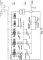
- figure 10 shows a flow chart showing the connections between the individual injection molding machines of a larger overall system. It shows that three injection molding machines for the production of pipette tips and two injection molding machines for the production of packaging containers for pipette tips as well as several quality assurance stations are connected to one another via transport devices (represented by solid lines) such that a total of three packaging devices are supplied with pipette tips and racks.
Landscapes
- Engineering & Computer Science (AREA)
- Manufacturing & Machinery (AREA)
- Mechanical Engineering (AREA)
- Health & Medical Sciences (AREA)
- Clinical Laboratory Science (AREA)
- Chemical & Material Sciences (AREA)
- Chemical Kinetics & Catalysis (AREA)
- Robotics (AREA)
- Injection Moulding Of Plastics Or The Like (AREA)
- Container Filling Or Packaging Operations (AREA)
Priority Applications (1)
| Application Number | Priority Date | Filing Date | Title |
|---|---|---|---|
| EP20195861.8A EP3967472A1 (fr) | 2020-09-11 | 2020-09-11 | Procédé et dispositif d'emballage des pièces moulées par injection |
Applications Claiming Priority (1)
| Application Number | Priority Date | Filing Date | Title |
|---|---|---|---|
| EP20195861.8A EP3967472A1 (fr) | 2020-09-11 | 2020-09-11 | Procédé et dispositif d'emballage des pièces moulées par injection |
Publications (1)
| Publication Number | Publication Date |
|---|---|
| EP3967472A1 true EP3967472A1 (fr) | 2022-03-16 |
Family
ID=72474174
Family Applications (1)
| Application Number | Title | Priority Date | Filing Date |
|---|---|---|---|
| EP20195861.8A Withdrawn EP3967472A1 (fr) | 2020-09-11 | 2020-09-11 | Procédé et dispositif d'emballage des pièces moulées par injection |
Country Status (1)
| Country | Link |
|---|---|
| EP (1) | EP3967472A1 (fr) |
Cited By (1)
| Publication number | Priority date | Publication date | Assignee | Title |
|---|---|---|---|---|
| WO2022200375A1 (fr) * | 2021-03-22 | 2022-09-29 | Gritec Ag | Procédé et dispositif de contrôle de pointes de pipettes |
Citations (2)
| Publication number | Priority date | Publication date | Assignee | Title |
|---|---|---|---|---|
| WO2015049350A1 (fr) | 2013-10-02 | 2015-04-09 | Hekuma Gmbh | Procédé et dispositif pour l'emballage de pièces moulées par injection |
| EP2868587A1 (fr) * | 2013-10-30 | 2015-05-06 | Waldorf Technik GmbH & Co. KG | Procédé d'emballage, dispositif d'emballage et installation de moulage par injection équipée de dispositif d'emballage |
-
2020
- 2020-09-11 EP EP20195861.8A patent/EP3967472A1/fr not_active Withdrawn
Patent Citations (2)
| Publication number | Priority date | Publication date | Assignee | Title |
|---|---|---|---|---|
| WO2015049350A1 (fr) | 2013-10-02 | 2015-04-09 | Hekuma Gmbh | Procédé et dispositif pour l'emballage de pièces moulées par injection |
| EP2868587A1 (fr) * | 2013-10-30 | 2015-05-06 | Waldorf Technik GmbH & Co. KG | Procédé d'emballage, dispositif d'emballage et installation de moulage par injection équipée de dispositif d'emballage |
Cited By (2)
| Publication number | Priority date | Publication date | Assignee | Title |
|---|---|---|---|---|
| WO2022200375A1 (fr) * | 2021-03-22 | 2022-09-29 | Gritec Ag | Procédé et dispositif de contrôle de pointes de pipettes |
| EP4313420A1 (fr) * | 2021-03-22 | 2024-02-07 | Gritec AG | Procédé et dispositif de contrôle de pointes de pipettes |
Similar Documents
| Publication | Publication Date | Title |
|---|---|---|
| EP2280873B1 (fr) | Remplisseuse et capsuleuse de contenants | |
| EP0305896B1 (fr) | Procédé pour positionner des bâtonnets dans des barquettes et dispositif pour la mise en oeuvre du procédé | |
| DE3542496C2 (de) | Verfahren und Vorrichtung zum Zuführen von Montageteilen | |
| DE29907459U1 (de) | Verpackungsmaschine | |
| EP3606689B1 (fr) | Procédé d'alimentation en rivets d'une riveuse | |
| EP2049063B1 (fr) | Dispositif et procédé d'éjection d'au moins une capsule. | |
| EP2826734A1 (fr) | Procédé et système de fabrication de ressorts cylindriques | |
| WO2020058135A1 (fr) | Procédé et dispositif d'acheminement de produits d'un premier processus vers un second processus dans une installation d'emballage | |
| DE69610965T2 (de) | Verfahren und automatisiertes Gerät zur Produktverstärkung für Verpackung | |
| AT391650B (de) | Anlage zur herstellung von formteilen aus kunststoff | |
| DE69605971T2 (de) | Verfahren und automatisierte Vorrichtung zum Verdichten von Produkten zur Verpackung | |
| EP3967472A1 (fr) | Procédé et dispositif d'emballage des pièces moulées par injection | |
| DE1817210A1 (de) | Vorrichtung zum automatischen Pruefen und Buendeln roehrenfoermiger Gegenstaende | |
| WO2017194760A1 (fr) | Procédé pour remplir une cassette à rivets d'éléments formant rivets | |
| DE69413503T2 (de) | Allzweckbearbeitungsmaschine für Anschlussdrähte | |
| DE29707324U1 (de) | Vorrichtung zum Sammeln und Palettieren von Flaschen | |
| DE602005004862T2 (de) | Einheit und Verfahren zum Transportieren von in einer Anzahl von aufeinanderliegenden Reihen angeordneten Behältern | |
| DE102016123770A1 (de) | System und Verfahren zum Umgang mit im Massenstrom bewegten Artikeln wie Getränkebehältnissen oder dergleichen | |
| EP3808530B1 (fr) | Procédé et agencement de remplissage des pièces en matière plastique | |
| EP2168874B1 (fr) | Dispositif pour transférer des produits d'un conteneur de stockage dans des récipients d'emballage | |
| DE3337243A1 (de) | Einrichtung zur fertigung gepresster gegenstaende | |
| EP2801531A2 (fr) | Procédé d'emballage, dispositif d'emballage et installation de moulage par injection équipée de dispositif d'emballage | |
| EP1051341B1 (fr) | Dispositif pour le traitement de bouteilles | |
| DE3819210A1 (de) | Werkzeugwechseleinrichtung fuer ein nc-gesteuertes fertigungssystem | |
| EP3827484B1 (fr) | Dispositif de machine de traitement de câble et procédé d'enlèvement des câbles d'un bac de réception d'une machine de traitement de câble |
Legal Events
| Date | Code | Title | Description |
|---|---|---|---|
| PUAI | Public reference made under article 153(3) epc to a published international application that has entered the european phase |
Free format text: ORIGINAL CODE: 0009012 |
|
| STAA | Information on the status of an ep patent application or granted ep patent |
Free format text: STATUS: THE APPLICATION HAS BEEN PUBLISHED |
|
| AK | Designated contracting states |
Kind code of ref document: A1 Designated state(s): AL AT BE BG CH CY CZ DE DK EE ES FI FR GB GR HR HU IE IS IT LI LT LU LV MC MK MT NL NO PL PT RO RS SE SI SK SM TR |
|
| STAA | Information on the status of an ep patent application or granted ep patent |
Free format text: STATUS: REQUEST FOR EXAMINATION WAS MADE |
|
| 17P | Request for examination filed |
Effective date: 20220815 |
|
| RBV | Designated contracting states (corrected) |
Designated state(s): AL AT BE BG CH CY CZ DE DK EE ES FI FR GB GR HR HU IE IS IT LI LT LU LV MC MK MT NL NO PL PT RO RS SE SI SK SM TR |
|
| STAA | Information on the status of an ep patent application or granted ep patent |
Free format text: STATUS: THE APPLICATION IS DEEMED TO BE WITHDRAWN |
|
| 18D | Application deemed to be withdrawn |
Effective date: 20240403 |