EP3967238B1 - Détermination de rotation dans un faisceau d'ultrasons - Google Patents
Détermination de rotation dans un faisceau d'ultrasons Download PDFInfo
- Publication number
- EP3967238B1 EP3967238B1 EP21201568.9A EP21201568A EP3967238B1 EP 3967238 B1 EP3967238 B1 EP 3967238B1 EP 21201568 A EP21201568 A EP 21201568A EP 3967238 B1 EP3967238 B1 EP 3967238B1
- Authority
- EP
- European Patent Office
- Prior art keywords
- ultrasound
- interventional device
- receiver
- imaging system
- receivers
- Prior art date
- Legal status (The legal status is an assumption and is not a legal conclusion. Google has not performed a legal analysis and makes no representation as to the accuracy of the status listed.)
- Active
Links
- 238000002604 ultrasonography Methods 0.000 title claims description 240
- 238000012285 ultrasound imaging Methods 0.000 claims description 54
- 238000000034 method Methods 0.000 claims description 24
- 238000003384 imaging method Methods 0.000 claims description 13
- 239000000758 substrate Substances 0.000 claims description 8
- 239000013598 vector Substances 0.000 claims description 8
- 238000004590 computer program Methods 0.000 claims description 6
- 229920000642 polymer Polymers 0.000 claims description 6
- 238000004891 communication Methods 0.000 claims description 5
- 238000001514 detection method Methods 0.000 claims description 5
- 230000005540 biological transmission Effects 0.000 claims description 4
- 239000000523 sample Substances 0.000 description 32
- 239000002033 PVDF binder Substances 0.000 description 6
- 229920002981 polyvinylidene fluoride Polymers 0.000 description 6
- 230000035945 sensitivity Effects 0.000 description 6
- 230000006870 function Effects 0.000 description 5
- 230000003287 optical effect Effects 0.000 description 4
- 210000001519 tissue Anatomy 0.000 description 4
- 230000007423 decrease Effects 0.000 description 2
- 230000003292 diminished effect Effects 0.000 description 2
- 239000011888 foil Substances 0.000 description 2
- 239000000463 material Substances 0.000 description 2
- 239000011159 matrix material Substances 0.000 description 2
- 210000002307 prostate Anatomy 0.000 description 2
- 239000004065 semiconductor Substances 0.000 description 2
- XPIIYLUXKKHAPJ-UHFFFAOYSA-N 1,1,2-trifluoroethene;hydrofluoride Chemical group F.FC=C(F)F XPIIYLUXKKHAPJ-UHFFFAOYSA-N 0.000 description 1
- 229920001166 Poly(vinylidene fluoride-co-trifluoroethylene) Polymers 0.000 description 1
- 239000004820 Pressure-sensitive adhesive Substances 0.000 description 1
- 230000003213 activating effect Effects 0.000 description 1
- 239000000853 adhesive Substances 0.000 description 1
- 230000001070 adhesive effect Effects 0.000 description 1
- 238000004458 analytical method Methods 0.000 description 1
- 210000001765 aortic valve Anatomy 0.000 description 1
- 238000003491 array Methods 0.000 description 1
- 230000009286 beneficial effect Effects 0.000 description 1
- 230000002596 correlated effect Effects 0.000 description 1
- 230000000875 corresponding effect Effects 0.000 description 1
- 230000008021 deposition Effects 0.000 description 1
- 238000002059 diagnostic imaging Methods 0.000 description 1
- 238000002592 echocardiography Methods 0.000 description 1
- 210000005003 heart tissue Anatomy 0.000 description 1
- 238000001990 intravenous administration Methods 0.000 description 1
- 210000005248 left atrial appendage Anatomy 0.000 description 1
- 230000004807 localization Effects 0.000 description 1
- 229920003229 poly(methyl methacrylate) Polymers 0.000 description 1
- 229920000139 polyethylene terephthalate Polymers 0.000 description 1
- 239000005020 polyethylene terephthalate Substances 0.000 description 1
- 239000004926 polymethyl methacrylate Substances 0.000 description 1
- 238000002310 reflectometry Methods 0.000 description 1
- 230000004044 response Effects 0.000 description 1
- 238000007789 sealing Methods 0.000 description 1
- 238000002603 single-photon emission computed tomography Methods 0.000 description 1
- 239000007787 solid Substances 0.000 description 1
- 230000002123 temporal effect Effects 0.000 description 1
- 238000002366 time-of-flight method Methods 0.000 description 1
Images


Classifications
-
- A—HUMAN NECESSITIES
- A61—MEDICAL OR VETERINARY SCIENCE; HYGIENE
- A61B—DIAGNOSIS; SURGERY; IDENTIFICATION
- A61B8/00—Diagnosis using ultrasonic, sonic or infrasonic waves
- A61B8/08—Detecting organic movements or changes, e.g. tumours, cysts, swellings
- A61B8/0833—Detecting organic movements or changes, e.g. tumours, cysts, swellings involving detecting or locating foreign bodies or organic structures
- A61B8/0841—Detecting organic movements or changes, e.g. tumours, cysts, swellings involving detecting or locating foreign bodies or organic structures for locating instruments
-
- A—HUMAN NECESSITIES
- A61—MEDICAL OR VETERINARY SCIENCE; HYGIENE
- A61B—DIAGNOSIS; SURGERY; IDENTIFICATION
- A61B17/00—Surgical instruments, devices or methods, e.g. tourniquets
- A61B17/34—Trocars; Puncturing needles
- A61B17/3403—Needle locating or guiding means
-
- A—HUMAN NECESSITIES
- A61—MEDICAL OR VETERINARY SCIENCE; HYGIENE
- A61B—DIAGNOSIS; SURGERY; IDENTIFICATION
- A61B34/00—Computer-aided surgery; Manipulators or robots specially adapted for use in surgery
- A61B34/20—Surgical navigation systems; Devices for tracking or guiding surgical instruments, e.g. for frameless stereotaxis
-
- A—HUMAN NECESSITIES
- A61—MEDICAL OR VETERINARY SCIENCE; HYGIENE
- A61B—DIAGNOSIS; SURGERY; IDENTIFICATION
- A61B8/00—Diagnosis using ultrasonic, sonic or infrasonic waves
- A61B8/12—Diagnosis using ultrasonic, sonic or infrasonic waves in body cavities or body tracts, e.g. by using catheters
-
- A—HUMAN NECESSITIES
- A61—MEDICAL OR VETERINARY SCIENCE; HYGIENE
- A61B—DIAGNOSIS; SURGERY; IDENTIFICATION
- A61B8/00—Diagnosis using ultrasonic, sonic or infrasonic waves
- A61B8/13—Tomography
- A61B8/14—Echo-tomography
- A61B8/145—Echo-tomography characterised by scanning multiple planes
-
- A—HUMAN NECESSITIES
- A61—MEDICAL OR VETERINARY SCIENCE; HYGIENE
- A61B—DIAGNOSIS; SURGERY; IDENTIFICATION
- A61B8/00—Diagnosis using ultrasonic, sonic or infrasonic waves
- A61B8/44—Constructional features of the ultrasonic, sonic or infrasonic diagnostic device
- A61B8/4483—Constructional features of the ultrasonic, sonic or infrasonic diagnostic device characterised by features of the ultrasound transducer
- A61B8/4488—Constructional features of the ultrasonic, sonic or infrasonic diagnostic device characterised by features of the ultrasound transducer the transducer being a phased array
-
- A—HUMAN NECESSITIES
- A61—MEDICAL OR VETERINARY SCIENCE; HYGIENE
- A61B—DIAGNOSIS; SURGERY; IDENTIFICATION
- A61B8/00—Diagnosis using ultrasonic, sonic or infrasonic waves
- A61B8/52—Devices using data or image processing specially adapted for diagnosis using ultrasonic, sonic or infrasonic waves
- A61B8/5215—Devices using data or image processing specially adapted for diagnosis using ultrasonic, sonic or infrasonic waves involving processing of medical diagnostic data
- A61B8/5238—Devices using data or image processing specially adapted for diagnosis using ultrasonic, sonic or infrasonic waves involving processing of medical diagnostic data for combining image data of patient, e.g. merging several images from different acquisition modes into one image
- A61B8/5246—Devices using data or image processing specially adapted for diagnosis using ultrasonic, sonic or infrasonic waves involving processing of medical diagnostic data for combining image data of patient, e.g. merging several images from different acquisition modes into one image combining images from the same or different imaging techniques, e.g. color Doppler and B-mode
-
- A—HUMAN NECESSITIES
- A61—MEDICAL OR VETERINARY SCIENCE; HYGIENE
- A61B—DIAGNOSIS; SURGERY; IDENTIFICATION
- A61B17/00—Surgical instruments, devices or methods, e.g. tourniquets
- A61B17/34—Trocars; Puncturing needles
- A61B17/3403—Needle locating or guiding means
- A61B2017/3413—Needle locating or guiding means guided by ultrasound
-
- A—HUMAN NECESSITIES
- A61—MEDICAL OR VETERINARY SCIENCE; HYGIENE
- A61B—DIAGNOSIS; SURGERY; IDENTIFICATION
- A61B34/00—Computer-aided surgery; Manipulators or robots specially adapted for use in surgery
- A61B34/20—Surgical navigation systems; Devices for tracking or guiding surgical instruments, e.g. for frameless stereotaxis
- A61B2034/2046—Tracking techniques
- A61B2034/2063—Acoustic tracking systems, e.g. using ultrasound
-
- A—HUMAN NECESSITIES
- A61—MEDICAL OR VETERINARY SCIENCE; HYGIENE
- A61B—DIAGNOSIS; SURGERY; IDENTIFICATION
- A61B34/00—Computer-aided surgery; Manipulators or robots specially adapted for use in surgery
- A61B34/20—Surgical navigation systems; Devices for tracking or guiding surgical instruments, e.g. for frameless stereotaxis
- A61B2034/2046—Tracking techniques
- A61B2034/2065—Tracking using image or pattern recognition
-
- A—HUMAN NECESSITIES
- A61—MEDICAL OR VETERINARY SCIENCE; HYGIENE
- A61B—DIAGNOSIS; SURGERY; IDENTIFICATION
- A61B8/00—Diagnosis using ultrasonic, sonic or infrasonic waves
- A61B8/13—Tomography
- A61B8/15—Transmission-tomography
-
- A—HUMAN NECESSITIES
- A61—MEDICAL OR VETERINARY SCIENCE; HYGIENE
- A61B—DIAGNOSIS; SURGERY; IDENTIFICATION
- A61B8/00—Diagnosis using ultrasonic, sonic or infrasonic waves
- A61B8/42—Details of probe positioning or probe attachment to the patient
- A61B8/4245—Details of probe positioning or probe attachment to the patient involving determining the position of the probe, e.g. with respect to an external reference frame or to the patient
-
- A—HUMAN NECESSITIES
- A61—MEDICAL OR VETERINARY SCIENCE; HYGIENE
- A61B—DIAGNOSIS; SURGERY; IDENTIFICATION
- A61B8/00—Diagnosis using ultrasonic, sonic or infrasonic waves
- A61B8/44—Constructional features of the ultrasonic, sonic or infrasonic diagnostic device
- A61B8/4444—Constructional features of the ultrasonic, sonic or infrasonic diagnostic device related to the probe
- A61B8/445—Details of catheter construction
-
- A—HUMAN NECESSITIES
- A61—MEDICAL OR VETERINARY SCIENCE; HYGIENE
- A61B—DIAGNOSIS; SURGERY; IDENTIFICATION
- A61B8/00—Diagnosis using ultrasonic, sonic or infrasonic waves
- A61B8/44—Constructional features of the ultrasonic, sonic or infrasonic diagnostic device
- A61B8/4477—Constructional features of the ultrasonic, sonic or infrasonic diagnostic device using several separate ultrasound transducers or probes
-
- A—HUMAN NECESSITIES
- A61—MEDICAL OR VETERINARY SCIENCE; HYGIENE
- A61B—DIAGNOSIS; SURGERY; IDENTIFICATION
- A61B8/00—Diagnosis using ultrasonic, sonic or infrasonic waves
- A61B8/44—Constructional features of the ultrasonic, sonic or infrasonic diagnostic device
- A61B8/4483—Constructional features of the ultrasonic, sonic or infrasonic diagnostic device characterised by features of the ultrasound transducer
- A61B8/4494—Constructional features of the ultrasonic, sonic or infrasonic diagnostic device characterised by features of the ultrasound transducer characterised by the arrangement of the transducer elements
-
- A—HUMAN NECESSITIES
- A61—MEDICAL OR VETERINARY SCIENCE; HYGIENE
- A61B—DIAGNOSIS; SURGERY; IDENTIFICATION
- A61B8/00—Diagnosis using ultrasonic, sonic or infrasonic waves
- A61B8/52—Devices using data or image processing specially adapted for diagnosis using ultrasonic, sonic or infrasonic waves
- A61B8/5207—Devices using data or image processing specially adapted for diagnosis using ultrasonic, sonic or infrasonic waves involving processing of raw data to produce diagnostic data, e.g. for generating an image
-
- A—HUMAN NECESSITIES
- A61—MEDICAL OR VETERINARY SCIENCE; HYGIENE
- A61M—DEVICES FOR INTRODUCING MEDIA INTO, OR ONTO, THE BODY; DEVICES FOR TRANSDUCING BODY MEDIA OR FOR TAKING MEDIA FROM THE BODY; DEVICES FOR PRODUCING OR ENDING SLEEP OR STUPOR
- A61M25/00—Catheters; Hollow probes
- A61M25/01—Introducing, guiding, advancing, emplacing or holding catheters
- A61M25/0105—Steering means as part of the catheter or advancing means; Markers for positioning
- A61M2025/0166—Sensors, electrodes or the like for guiding the catheter to a target zone, e.g. image guided or magnetically guided
Definitions
- the present invention relates to determining the rotation of an interventional device in an ultrasound beam.
- the ultrasound beam may be a beam of medical ultrasound imaging system.
- Medical devices such as needles, catheters and interventional tools are often difficult to visualize in an ultrasound image due to the specular nature of their reflectivity, particularly at unfavorable incidence angles.
- publication WO/2011/138698 discloses to attach an ultrasound receiver to a medical device.
- the ultrasound receiver detects ultrasound signals from the ultrasound field of an ultrasound imaging probe, and processes these signals with an ultrasound receive beamformer.
- the ultrasound receive beamformer is configured for one-way only beamforming of transmissive ultrasound from the ultrasound field, and is used to track the position of the ultrasound receiver and thus the medical device in relation to the ultrasound field.
- US6216029B1 describes an arrangement for directing a needle towards a target within an ultrasound image.
- the position of an ultrasound probe is determined in relation to a remotely-located position sensing unit by attaching three infrared ultrasonic transponders to the ultrasound probe.
- the transponders generate coded ultrasound signals in response to infrared signals emitted by infrared ultrasonic transceivers that form part of the position sensing unit.
- the ultrasound signals received by the position sensing unit provide triangulation information for the controller to calculate the position of the ultrasound probe in three dimensional space.
- US6216029B1 further describes a similar arrangement for locating the position of the needle respective the position sensing unit. Subsequently the trajectory of the needle point is displayed in the ultrasound image based on the positions of the ultrasound probe and the needle relative to the position sensing unit.
- US2004/0193042A1 discloses a 3D ultrasonic diagnostic imaging system which is operated to guide an interventional device.
- ultrasound pulses from an ultrasound imaging probe are received by a transducer on the interventional device to determine its position based on the time of flight of the pulses.
- US2013/310679 A1 discloses a three-dimensional transurethral ultrasound system that includes a transurethral ultrasound probe, an ultrasound data processor configured to communicate with the transurethral ultrasound probe to receive ultrasound signals from the transurethral ultrasound probe and to output ultrasound imaging signals for three-dimensional ultrasound images of at least a portion of a patient's prostate, and a display system configured to communicate with the ultrasound data processor to receive the ultrasound imaging signals and to render three-dimensional ultrasound images of the at least the portion of the patient's prostate from the ultrasound imaging signals.
- US2005/261571A1 discloses a system and method for simultaneously tracking a position of a medical device and ablating a tissue within a body.
- the system includes a power supply, a navigation device, and a control circuit.
- the power supply generates a current that is suitable for ablating tissue, such as heart tissue.
- the navigation device establishes a three-dimensional reference coordinate system and identifies a location of an energy delivery device in relation to the established coordinate system.
- the control circuit switches or alternates between activating the power supply and acquiring ultrasound data that identifies the location of the medical device within the established coordinate system.
- US2014/276003A1 discloses a method for providing real-time guidance to an interventional device coupled to an ultrasound imaging system operating in a first mode and a second mode.
- the method includes, in the first mode, stopping transmission of ultrasound signals from a transducer of the ultrasound imaging apparatus, and transmitting, via an acoustic sensor mounted on a head portion of an interventional device, an ultrasound signal that is then received by the transducer to generate a first image of a location of the head portion; in a second mode, stopping transmitting ultrasound signals from the acoustic sensor, transmitting ultrasound signals via the transducer, and receiving echoes of the transmitted ultrasound signals to generate a second image of an object structure; and combining the first image with the second image to derive a third image displaying and highlighting a relative location of the head portion in the object structure.
- an interventional device which may be tracked in an ultrasound beam of a beamforming ultrasound imaging system.
- the device can be tracked using ultrasound receivers that are wrapped around the interventional device and which are configured to detect transmitted ultrasound signals from the ultrasound imaging system.
- the signals may be one-way transmitted ultrasound signals.
- the position of the ultrasound receivers and thus the position of the interventional device respective the beamforming ultrasound imaging system can be determined by correlating the transmitted ultrasound signals as detected by the ultrasound receivers with the beamforming beam sequence of the transmitted ultrasound signals.
- the interventional device includes a first linear sensor array of ultrasound receivers that are wrapped circumferentially around a longitudinal axis of the interventional device. Each ultrasound receiver has a length and a width, and the array extends along the width direction.
- the first linear sensor array is wrapped circumferentially around the interventional device with respect to the longitudinal axis such that the length of each ultrasound receiver is arranged lengthwise with respect to the axis.
- an interventional device is provided in which the ultrasound receivers in the array have different viewing angles in a radial direction with respect to the longitudinal axis.
- the signals detected by each of the ultrasound receivers vary in accordance with the rotational angle of the interventional device about its longitudinal axis respective the origin of the beam. For example, an ultrasound receiver that is rotated relatively towards the origin of the ultrasound beam such that it faces the ultrasound beam will detect a relatively larger signal because it intercepts a relatively large cross sectional area of the beam. By contrast an ultrasound receiver that is rotated relatively away from the origin of the same ultrasound beam will detect a relatively smaller signal due to the relatively smaller cross-sectional beam area intercepted by the receiver.
- the interventional device is rotated such that the ultrasound receiver is on the opposite side to the origin of the ultrasound beam the signal is further diminished owing to shadowing by the body of the interventional device.
- the rotation of the interventional device about its longitudinal axis can be determined in relation to the origin of the ultrasound beam.
- the receiver, or group of receivers, that provide the maximum detected signal are thus used to identify the portion of the interventional device that is closest to the origin, i.e. the zenith, of the ultrasound beam.
- the receiver, or group of receivers, that provide the earliest detected signal may be used to identify the portion of the interventional device that is closest to the origin, i.e. the zenith, of the ultrasound beam.
- each ultrasound receiver in the first linear sensor array is greater that its width. This improves the axial range of the interventional device over which sensing can be achieved, and also improves the signal to noise ratio of signals detected by each receiver.
- gaps between the ultrasound receivers are defined in relation to the ultrasound receiver width. This arrangement reduces the total rotational angle over which the interventional device has a reduced-sensitivity to ultrasound signals, thereby improving the accuracy with which the angular rotation can be determined.
- the first linear sensor array is wrapped around the longitudinal axis of the interventional device in the form of a spiral.
- the spiral wrapping arrangement provides a robust method of attaching the ultrasound transducers and the electrical interconnections associated therewith to interventional device. Moreover it provides an efficient arrangement for routing the electrical interconnections to the proximal end of the interventional device.
- the interventional device includes a second linear sensor array that is also wrapped around the interventional device circumferentially with respect to the longitudinal axis. Moreover, each gap between the ultrasound receivers in the first linear sensor array coincides with, or is aligned with, a receiver in the second linear sensor array in a lengthwise direction with respect to the axis. This arrangement improves the rotational sensitivity at rotational angles that correspond to the gaps of the first linear sensor array.
- the first linear sensor array comprises an even number of ultrasound receivers that are arranged in diametrically-opposing pairs with respect to the longitudinal axis.
- the ultrasound receivers are electrically connected such that ultrasound signals detected by the receivers in each pair are subtracted. This arrangement simplifies the complexity of the electrical interconnections associated with the ultrasound receivers.
- the interventional device whose rotation is determined is a needle. It is however to be appreciated that the invention also finds application in determining the rotation of other interventional devices such as a catheter, a guidewire, a probe, an endoscope, an electrode, a robot, a filter device, a balloon device, a stent, a mitral clip, a left atrial appendage closure device, an aortic valve, a pacemaker, an intravenous line, a drainage line, a surgical tool such as a tissue sealing device or a tissue cutting device.
- interventional devices such as a catheter, a guidewire, a probe, an endoscope, an electrode, a robot, a filter device, a balloon device, a stent, a mitral clip, a left atrial appendage closure device, an aortic valve, a pacemaker, an intravenous line, a drainage line, a surgical tool such as a tissue sealing device or a tissue cutting device.
- the embodiments described relate to determining the rotation of an interventional device in the various beams of a 2D ultrasound imaging probe as the beamforming ultrasound imaging system. It is also to be appreciated that the invention finds application with other types of beamforming ultrasound imaging systems such as a 3D imaging probe, a transesophageal probe (TEE), transthoracic probe (TTE), transnasal probe (TNE), intracardiac probe (ICE).
- TEE transesophageal probe
- TTE transthoracic probe
- TNE transnasal probe
- ICE intracardiac probe
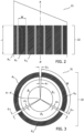
- Fig. 1 illustrates in Fig. 1A a side-view of an interventional device 11a that includes a first linear sensor array 12 of ultrasound receivers R 1..n in accordance with a first aspect of the invention, and in Fig. 1B the same interventional device 11b in plan-view, positioned in an ultrasound beam B at rotational angle ⁇ to the origin of the beam at source S, and in Fig. 1C the signal, Sig, detected by each ultrasound receiver R 1 , R 2 , R n as the rotational angle ⁇ of the interventional device is varied.
- the needle illustrated in Fig. 1A has a longitudinal axis A- A' about which linear sensor array 12 comprising three ultrasound receivers R 1 , R 2 , R n are wrapped circumferentially.
- Each ultrasound receiver has a length L and a width W and the array extends along the width direction.
- the length L of each ultrasound receiver R 1 , R 2 , R n is arranged lengthwise with respect to the axis A - A'.
- interventional device 11a is provided with three ultrasound receivers R 1 , R 2 , R n that have different radial viewing angles with respect to longitudinal axis A - A'.
- Fig. 1B illustrates the same interventional device as in Fig. 1A , i.e.
- Beam B may be an ultrasound beam of a beamforming ultrasound imaging system such as a 2D ultrasound imaging probe.
- the complete ultrasound field generated by the 2D ultrasound imaging probe typically comprises a fan of a plurality of beams such as beam B, which together are used to probe and thus generate a planar image of a slice through a region of interest.
- the beam origin at source S is between ultrasound receivers R 1 and R n .
- longitudinal axis A - A' of interventional device 11b is perpendicular the plane of the figure.
- FIG. 1C illustrates the signal, Sig, detected by each ultrasound receiver R 1 , R 2 , R n as the rotational angle ⁇ of the interventional device is varied.
- the angle ⁇ is the rotational angle about axis A - A' of the interventional device to the origin of the beam B.
- the ultrasound receivers R 1 , R 2 , R n in Fig. 1 are each sensitive to a portion of the complete 360° viewing angle around axis A - A', by comparing each of the signals detected by receivers R 1 , R 2 , R n , the rotation ⁇ of the interventional device 11 about axis A - A' respective the origin of beam B can be determined. For example, when ultrasound receiver R 1 is rotated relatively towards ultrasound beam B such that it faces the center of source S of beam B, ultrasound receiver R 1 will detect a relatively larger signal because it intercepts the largest possible large cross sectional area of beam B.
- ultrasound receiver R 2 that at this rotational position is rotated relatively away from ultrasound beam B will detect a relatively smaller signal due to the reduced cross-sectional beam area intercepted by receiver R 2 .
- interventional device 11b is rotated such that ultrasound receiver R 1 is on the opposite side to the ultrasound beam, i.e. facing directly away from source S, its detected signal is further diminished owing to shadowing by the body of the interventional device 11b.
- This arrangement typically provides that each ultrasound receiver has maximum sensitivity in a substantially normal direction to axis A - A', i.e. within about ⁇ 10 degrees of the normal direction.
- the rotation of the interventional device 11b about its longitudinal axis A- A' can be determined in relation to the origin of ultrasound beam B, i.e. to the center of beam source S.
- the ultrasound receiver, or group of receivers, that detect the maximum signal are used to indicate the portion of the interventional device that is closest to the center of source S, i.e. to the zenith, of ultrasound beam B.
- the ultrasound receiver, or group of receivers, that detect the earliest signal are used to indicate the portion of the interventional device that is closest to the center of source S, i.e. to the zenith, of ultrasound beam B.
- Fig. 1 illustrates a first linear sensing array 12 having three ultrasound receivers
- two or more receivers are in principle sufficient for determining the rotation of the interventional device. This is because two receivers can be at least used to indicate which of the two possible 180° portions of the illustrated needle is closest to the center of source S.
- the rotational angle sensed by each sensor decreases, thereby improving the angular resolution of the device.
- the signals from several ultrasound transducers may thus provide signals that are close to their maximum level.
- the receiver that is closest to the center of ultrasound source S by analyzing the signals detected by the ultrasound receivers and determining the geometric center of the magnitudes of these detected signals, for example by fitting a function such as a Gaussian or a step-function to their spatial distribution and identifying the rotation based on the receiver that corresponds to the peak of the Gaussian function or to the center of the step function.
- a function such as a Gaussian or a step-function
- Fig. 2 illustrates in side-view a second embodiment of the invention in which the length L of each ultrasound receiver R 1 , R 2 , R n wrapped around longitudinal axis A- A' of interventional device 21 is greater than its width W.
- a drawback of improving the angular resolution of the linear sensing array of the Fig. 1 embodiment by reducing the width of each ultrasound receiver in the array is that this reduces the signal to noise ratio of signals detected by each ultrasound receiver.
- the inventors have further realized that this reduction in signal to noise ratio can in part be compensated-for by increasing the length of each ultrasound receiver.
- each receiver in this way permits the determination of the rotation of the interventional device along a longer length of the axis A- A'. In so doing the rotation of the device can be determined when an otherwise shorter sensor would lie outside a finite ultrasound beam.
- This extension of the axis of the interventional device over which rotation can be determined is particularly useful in planar ultrasound imaging systems when an otherwise shorter sensor would lie in an out-of-plane position.
- Fig. 3 illustrates in plan-view a third embodiment of the invention in which ultrasound receivers R 1 , R 2 , R n of first sensor array 32 that are wrapped around longitudinal axis A - A' of interventional device 31 are separated by gaps Gi, G 2 , G n .
- the angle ⁇ 1 , ⁇ 2 , ⁇ n subtended by each gap Gi, G 2 , G n from the axis A - A' is less than or equal to the angle ⁇ 1 , ⁇ 2 , ⁇ n subtended by the width W of each ultrasound receiver from the axis A - A'.
- the sensitivity of the interventional device to an ultrasound beam is reduced in the gaps between each ultrasound sensor.
- the arrangement of the third embodiment reduces the total rotational angle over which the interventional device has low-sensitivity to ultrasound, thereby improving the accuracy with which the angular rotation can be determined.
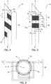
- Fig. 4 illustrates in side-view a fourth embodiment of the invention in which first linear sensor array 42 that includes ultrasound receivers R 1..n is attached to a substrate and the substrate is wrapped around longitudinal axis A - A' of interventional device 41 in the form of a spiral.
- the substrate may for example be a foil that is formed from a polymer such as PET, PMMA, PVDF and the like.
- the substrate may include electrical wires or tracks that are electrically connected to the receivers for making electrical contact to an external electrical circuit.
- a drawback to improving the rotational sensitivity of the interventional device by reducing the width W of each ultrasound receiver is the reduction in signal detected by each receiver.
- each receiver 4 compensates for the reduced width of each receiver by providing a plurality of individual receivers that each view the same, or an overlapping angular range. Moreover the individual receivers can be grouped together dynamically, for example using external electrical circuitry. This can be used to provide an increased signal across any predetermined rotational range.
- interventional device 41 could be configured to operate in a first mode in which the signals from a first receiver group in which each receiver is sensitive to a portion of a first angular range are grouped together electronically and summed to provide a first rotation signal having a first angular-resolution, or in a second mode in which the signals from a second receiver group in which each receiver is sensitive to a portion of a second angular range are grouped together electronically and summed to provide a second rotation signal having a second angular-resolution.
- relatively higher or relatively lower angular resolution may be achieved by dynamically adjusting the receiver grouping.
- Fig. 5 illustrates in side-view a fifth embodiment of the invention in which first linear sensor array 52 and second linear sensor array 53 are both wrapped around longitudinal axis A - A' of interventional device 51.
- Second linear sensor array 53 includes a plurality of ultrasound receivers R a1 , R a2 , R an , each separated by a space S 1 , S 2 , S n .
- Second linear sensor array 53 is wrapped around interventional device 51 circumferentially with respect to its axis A - A' such that each gap G 1 , G 2 , G n between the ultrasound receivers of the first linear sensor array 52 coincides with a receiver of the second linear sensor array R a1 , R a2 , R an , in a lengthwise direction with respect to the axis A - A'.
- a relatively smaller ultrasound receiver signal is detected at rotational angles ⁇ that coincide with a gap between the ultrasound receivers in an array, as compared to at rotational angles that coincide with an ultrasound receiver.
- the first linear sensor array 52 and the second linear sensor array 53 are axially separated with respect to the axis A - A' by a distance, d, that is greater than or equal to 1 mm.
- An ultrasound receiver position from the first linear sensing array 52 that is closest to the ultrasound beam source provides a point on the interventional device that is indicative of its position and its rotation.
- an ultrasound receiver position from the second linear sensing array 53 that is closest to the ultrasound beam source provides a second point on the interventional device that is indicative of its position and its rotation. Because the positions of these nearest-receivers are fixed with respect to the interventional device, together these points can be used to determine a trajectory of the interventional device. Improved sensitivity to the trajectory is provided by offsetting the two linear sensor arrays along the axis of the interventional device by at least 1 mm.
- Fig. 6 illustrates in plan-view a sixth embodiment of the invention in which first linear sensor array 62 comprising an even number of ultrasound receivers R 1 , R 2 , R 3 , R 4 are wrapped around longitudinal axis A - A' of interventional device 61 and in which the ultrasound receivers are arranged in diametrically-opposing pairs P 1 , P 2 , with respect to the axis.
- each ultrasound receiver comprises a piezoelectric element having a polling vector, as indicated by the arrows in each of R 1 , R 2 , R 3 , R 4 .
- Fig. 6 illustrates in plan-view a sixth embodiment of the invention in which first linear sensor array 62 comprising an even number of ultrasound receivers R 1 , R 2 , R 3 , R 4 are wrapped around longitudinal axis A - A' of interventional device 61 and in which the ultrasound receivers are arranged in diametrically-opposing pairs P 1 , P 2 , with respect to the axis.
- the ultrasound receivers in each pair are arranged such that for each pair both: i) the polling vectors of the ultrasound receivers are mutually opposed with respect to the axis A - A'; and ii) the ultrasound receivers are electrically connected in parallel such that their polling vectors are mutually opposed.
- Piezoelectric elements inherently have such a polling vector, this being indicative of the polarity of the electrical signal that will be generated across the electrodes of the piezoelectric element when the compressive phase of ultrasound wave impinges thereupon.
- the arrangement of Fig. 6 provides that the combined signal from each receiver pair is indicative of the difference in their detected signals.
- the combined signal from the closest detector in the pair to the ultrasound beam is enhanced, thereby improving the signal to noise ratio of the detected signals from each pair.
- the number of electrical connections that needs to be made to the distal end of the interventional device in order to analyze and/or process the detected signals is reduced, thereby simplifying the complexity of the electrical interconnections associated with the ultrasound receivers.
- the ultrasound receivers in the described embodiments are preferably piezoelectric devices. Many types of hard or soft piezoelectric materials are suitable for use as such, these being well known in the art. However, preferably the ultrasound receivers are formed from a piezoelectric polymer. Piezoelectric polymers advantageously provide increased flexibility and thus may be conformally wrapped around the axis of an interventional device such as a needle. Suitable piezoelectric polymers include Polyvinylidene fluoride, i.e. PVDF, or a PVDF co-polymer such as polyvinylidene fluoride trifluoroethylene (P(VDF-TrFE)) or a PVDF ter-polymer such as P(VDF-TrFE-CTFE).
- PVDF Polyvinylidene fluoride
- PVDF polyvinylidene fluoride trifluoroethylene
- PVDF ter-polymer such as P(VDF-TrFE-CTFE
- the ultrasound receiver may for example be formed by sandwiching the piezoelectric material and the electrical interconnections associated therewith between two pressure sensitive adhesive, i.e. PSA, surfaces of two PET sheets to form a foil in order to facilitate its attachment to the interventional device.
- PSA pressure sensitive adhesive
- the ultrasound transducers may in general be attached to the interventional device using a variety of techniques in addition to the use of a PSA layer from one of the above-described PET sheets. Such techniques include deposition, printing, and the use of adhesives.
- Fig. 7 illustrates an ultrasound imaging arrangement 79 in which various embodiments of the invention may be used, the arrangement including a beamforming ultrasound imaging system 74, and an ultrasound tracking unit 75.
- Beamforming ultrasound imaging system 74 includes an exemplary 2D planar ultrasound imaging probe 76, and a console 77. As illustrated, 2D planar ultrasound imaging probe 76 generates an ultrasound field in the form of a fan comprising multiple ultrasound beams B 1..k . 2D planar ultrasound imaging probe 76 is operationally connected to console 77, for example by wired or wireless means, as indicated by the connecting arrow.
- Console 77 includes imaging system processor ISP, imaging system interface ISI and display DISP as shown. Console 77 may be used to supervise a medical procedure.
- 2D ultrasound imaging probe 76 includes a one-dimensional array of ultrasound transceivers (not shown) for transmitting and receiving ultrasound energy from a volume of interest VOI.
- Console 77 may also include electronic driver and receiver circuitry (not shown) that is configured to amplify and/ or to adjust the phase of signals transmitted by or received by 2D ultrasound imaging probe 76 in order to generate and detect ultrasound signals in beams B 1..k .
- Console 77 may also include a memory (not shown) for storing programs and applications.
- the memory may for example store ultrasound beam control software that is configured to control the sequence of ultrasound signals transmitted by and/or received by 2D ultrasound imaging probe 76. It is to be noted however that whilst some of the ultrasound imaging system items are described above as being located within console 77, some of these items may alternatively be located within 2D ultrasound imaging probe 76, as is the case for example in the Philips VISIQ ultrasound imaging system.
- Ultrasound tracking unit 75 includes a tracking processor 78 and interventional device 71, the two units being in communication by means of either wired or wireless communication as indicated by the connecting arrow. Wireless communication may for example be provided using an optical, infrared, or an RF communication link. Ultrasound tracking unit 75 may also include electronic circuitry (not shown) that is configured to amplify signals detected by ultrasound receivers R 1 , R 2 , R n that are disposed circumferentially about longitudinal axis A- A' of interventional device 71.
- ultrasound tracking unit 75 may be used to track the rotation, and furthermore the position and orientation, of interventional device 71 in one of the ultrasound beams B 1..k of 2D ultrasound imaging probe 76.
- the distance determined above is the distance between the ultrasound beam's origin and the portion of interventional device 71 to which the nearest ultrasound receiver of the first linear sensor array 72 is attached, that is determined using the so-described time-of-flight method. Note that although the speed of ultrasound propagation may vary within the volume of interest VOI, this does not translate into a distance, or range error in the corresponding ultrasound image because such variation is also reflected on the ultrasound images.
- the following method step can be used: correlating the emitted beam sequence of the plurality of beams with the signals received by the ultrasound receiver R 1 , R 2 , R n having the maximum received signal.
- the time of emission of each beam of the plurality of beams is matched with the time of detection of the maximum signal, whilst compensating for the time delay between transmission and detection, to identify the beam B 1..k associated with the maximum signal.
- the angle of the ultrasound receiver in relation to the beamforming imaging system is provided because this angle is defined by the beam angle of the identified beam.
- the identification of which ultrasound beam the detector is located in is based on the following principle.
- a 2D ultrasound imaging probe emits ultrasound beams that regularly sample the volume of interest VOI in an array of beams B 1..k .
- the temporal signals detected by the ultrasound receivers R 1 , R 2 , R n during the acquisition of one image by the ultrasound imaging system are formatted in a two-dimensional B 1..k by time "data matrix".
- the time of detection is correlated, i.e. compared with the time of emission of each beam to determine the position that best fits the detected signals.
- a maximum intensity projection "MIP" of the "data matrix” over the time dimension is performed to yield a 1D MIP vector on which a Gaussian fit is applied.
- the Gaussian center is used to estimate the angular coordinates of the receiver in the ultrasound coordinate system.
- the methods described above i.e. the tracking of the rotation, the determining of the distance, and the identification of the ultrasound beam, provide an accurate indication of the position and rotation of the interventional device respective the beamforming ultrasound imaging system.
- these may subsequently be used to register an ultrasound image provided by the beamforming ultrasound imaging system 74, with a second image that includes the interventional device 71 and which is provided by a second imaging system (not shown in Fig. 7 ).
- the registration may be performed by aligning the coordinate systems of the ultrasound and the second imaging system based on the position and/ or the orientation of the interventional device as provided by ultrasound tracking unit 75.
- the second imaging system may for example be a PET, a SPECT, a CT, an x-ray or an MR imaging system.
- the ultrasound image provides, in the above described case, a 2D image slice through a volume of interest. By combining this image with that of the second imaging system, improved navigation is provided because features that are visible in the second image often provide valuable landmarks.
- the image from the second imaging system may be a live image, or a previously-generated "navigation" image.
- any of the above-described methods may for example be carried out by tracking processor 78 or by imaging system processor ISP of console 77 illustrated in Fig. 7 .
- the functions of each of these units may be combined into a single processor or distributed amongst separate processors.
- the method may be recorded in the form of instructions which when executed on a processor cause the processor to carry out these method steps.
- the computer program product may be provided by dedicated hardware as well as hardware capable of executing software in association with appropriate software.
- the functions can be provided by a single dedicated processor, by a single shared processor, or by a plurality of individual processors, some of which can be shared.
- processor or “controller” should not be construed to refer exclusively to hardware capable of executing software, and can implicitly include, without limitation, digital signal processor "DSP” hardware, read only memory “ROM” for storing software, random access memory “RAM”, non-volatile storage, etc.
- DSP digital signal processor
- ROM read only memory
- RAM random access memory
- embodiments of the present invention can take the form of a computer program product accessible from a computer-usable or computer-readable storage medium providing program code for use by or in connection with a computer or any instruction execution system.
- a computer-usable or computer readable storage medium can be any apparatus that may include, store, communicate, propagate, or transport the program for use by or in connection with the instruction execution system, apparatus, or device.
- the medium can be an electronic, magnetic, optical, electromagnetic, infrared, or semiconductor system, or apparatus or device, or a propagation medium.
- Examples of a computer-readable medium include a semiconductor or solid state memory, magnetic tape, a removable computer diskette, a random access memory "RAM”, a read-only memory "ROM”, a rigid magnetic disk and an optical disk.
- Current examples of optical disks include compact disk - read only memory "CD-ROM”, compact disk - read/write "CD-R/W”, Blu-Ray TM and DVD.
Claims (10)
- Dispositif d'intervention (11, 21, 31, 41, 51, 61, 71) destiné à être suivi dans un faisceau ultrasonore d'un système d'imagerie ultrasonore à formation de faisceau en corrélant les signaux ultrasonores transmis par le système d'imagerie ultrasonore à formation de faisceau, tels que détectés par les récepteurs ultrasonores attachés au dispositif d'intervention, avec la séquence de faisceau à formation de faisceau des signaux ultrasonores; le dispositif d'intervention comprenant: un axe longitudinal (A - A'); un premier réseau de capteurs linéaires (12, 22, 42, 52) comprenant plusieurs récepteurs ultrasonores (R1..n), chaque récepteur ultrasonore ayant une longueur (L) et une largeur (W), et dans lequel le réseau s'étend le long de la direction de la largeur (W); dans lequel le premier réseau de capteurs linéaires est enroulé circonférentiellement autour du dispositif d'intervention par rapport à l'axe (A - A'), de sorte que la longueur (L) de chaque récepteur ultrasonore est disposée dans le sens de la longueur par rapport à l'axe (A - A'), le premier réseau de capteurs linéaires (12, 22, 42, 52) est fixé à un substrat et le substrat est enroulé autour du dispositif d'intervention sous la forme d'une spirale.
- Dispositif d'intervention (31) selon la revendication précédente dans lequel les récepteurs ultrasonores (R1..n) sont chacun séparés par un espace (G1..n); et dans lequel l'angle (α1..n) sous-tendu par chaque espace (G1..n) par rapport à l'axe (A - A') est inférieur ou égal à l'angle (β1..n) sous-tendu par la largeur (W) de chaque récepteur ultrasonore par rapport à l'axe (A - A').
- Dispositif d'intervention (61) selon l'une des revendications 1 ou 2, dans lequel: le premier réseau de capteurs linéaires (62) comprend un nombre pair de récepteurs ultrasonores (R1, R2, R3, R4) qui sont disposés en paires diamétralement opposées (P1, P2) par rapport à l'axe (A - A'); et dans lequel chaque récepteur ultrasonore (R1, R2, R3, R4) comprend un élément piézoélectrique ayant un vecteur de sondage; et dans lequel les récepteurs ultrasonores de chaque paire (P1, P2) sont disposés de telle sorte que, pour chaque paire (P1, P2), à la fois les vecteurs de sondage des récepteurs ultrasonores sont mutuellement opposés par rapport à l'axe (A - A'); et les récepteurs ultrasonores sont connectés électriquement en parallèle de manière à ce que leurs vecteurs de sondage soient mutuellement opposés.
- Dispositif d'intervention selon l'une des revendications 1 à 3, dans lequel les récepteurs ultrasonores sont constitués d'un polymère piézoélectrique.
- Produit programme d'ordinateur comprenant des instructions qui, lorsqu'elles sont exécutées sur un processeur (78) en communication avec le système d'imagerie ultrasonore à formation de faisceau (74) et le dispositif d'intervention (71) de l'une quelconque des revendications 1 à 4, amènent le processeur à exécuter une méthode de détermination d'une rotation (Θ) du dispositif d'intervention (71) respective d'un faisceau ultrasonore (B1..K) u système d'imagerie ultrasonore à formation de faisceau (74); la méthode comprenant les étapes suivantes: recevoir, de chaque récepteur ultrasonore (R1, R2, Rn) du premier réseau de capteurs linéaires (72), des signaux indiquant les impulsions ultrasonores transmises par le système d'imagerie ultrasonore à formation de faisceau; comparer les signaux reçus; associer le récepteur ultrasonore (R1, R2, Rn) ayant soit le signal reçu le plus élevé, soit le signal reçu le plus tôt, à l'origine du faisceau ultrasonore.
- Produit de programme d'ordinateur selon la revendication 5 dans lequel le processeur est en outre configuré pour exécuter l'étape de la méthode consistant à: déterminer une distance (Dx) du récepteur ultrasonore (R1, R2, Rn) associée au signal maximal par rapport à l'origine du faisceau ultrasonore (B1..K) en fonction du délai (Δt) entre l'émission du faisceau ultrasonore et sa détection par le récepteur ultrasonore.
- Produit de programme d'ordinateur de la revendication 6 dans lequel le processeur est en outre configuré pour exécuter l'étape de la méthode consistant à: identifier dans quel faisceau ultrasonore d'une pluralité de faisceaux ultrasonores (B1..K) émis par le système d'imagerie ultrasonore à formation de faisceau se trouve le récepteur ultrasonore (R1, R2, Rn) associé au signal maximal est situé, en corrélant la séquence émise de la pluralité de faisceaux (B1..K) avec les signaux reçus par le récepteur ultrasonore (R1, R2, Rn) ayant le signal maximal reçu.
- Produit de programme d'ordinateur de la revendication 7 dans lequel le processeur est en outre configuré pour exécuter l'étape du procédé consistant à utiliser la position (B1..k, Dx) et la rotation (Θ) du dispositif d'intervention respectif du système d'imagerie ultrasonore à formation de faisceau (74) pour enregistrer une image ultrasonore fournie par le système d'imagerie ultrasonore à formation de faisceau (74) avec une deuxième image qui comprend le dispositif d'intervention (71) et qui est fournie par un deuxième système d'imagerie; la position (B1..k, Dx) étant déterminée sur la base de la distance déterminée (Dx) et du faisceau ultrasonore identifié (B1..k); la rotation (φ) étant déterminée sur la base du récepteur ultrasonore (R1, R2, Rn) associé au signal reçu maximal.
- Unité de suivi des ultrasons (75) comprenant le dispositif d'intervention (71) de l'une quelconque des revendications 1 à 4; et un processeur (78) configuré pour exécuter une méthode de détermination d'une rotation (Θ) du dispositif d'intervention (71) respective d'un faisceau ultrasonore (B1..k) du système d'imagerie ultrasonore à formation de faisceau (74); la méthode comprenant les étapes suivantes: recevoir, de chaque récepteur ultrasonore (R1, R2, Rn) du premier réseau de capteurs linéaires (72), des signaux indiquant les impulsions ultrasonores transmises par le système d'imagerie ultrasonore à formation de faisceau; comparer les signaux reçus; associer le récepteur ultrasonore (R1, R2, Rn) ayant soit le signal reçu le plus élevé, soit le signal reçu le plus tôt, à l'origine du faisceau ultrasonore.
- Dispositif d'imagerie à ultrasons (79) comprenant: un système d'imagerie ultrasonore à formation de faisceau (74); et l'unité de suivi ultrasonore (75) selon la revendication 9.
Applications Claiming Priority (3)
| Application Number | Priority Date | Filing Date | Title |
|---|---|---|---|
| EP15200090 | 2015-12-15 | ||
| EP16805385.8A EP3389502B1 (fr) | 2015-12-15 | 2016-12-01 | Détermination de rotation dans un faisceau d'ultrasons |
| PCT/EP2016/079356 WO2017102338A1 (fr) | 2015-12-15 | 2016-12-01 | Détermination de rotation dans un faisceau d'ultrasons |
Related Parent Applications (2)
| Application Number | Title | Priority Date | Filing Date |
|---|---|---|---|
| EP16805385.8A Division EP3389502B1 (fr) | 2015-12-15 | 2016-12-01 | Détermination de rotation dans un faisceau d'ultrasons |
| EP16805385.8A Division-Into EP3389502B1 (fr) | 2015-12-15 | 2016-12-01 | Détermination de rotation dans un faisceau d'ultrasons |
Publications (2)
| Publication Number | Publication Date |
|---|---|
| EP3967238A1 EP3967238A1 (fr) | 2022-03-16 |
| EP3967238B1 true EP3967238B1 (fr) | 2024-02-07 |
Family
ID=54849893
Family Applications (2)
| Application Number | Title | Priority Date | Filing Date |
|---|---|---|---|
| EP21201568.9A Active EP3967238B1 (fr) | 2015-12-15 | 2016-12-01 | Détermination de rotation dans un faisceau d'ultrasons |
| EP16805385.8A Active EP3389502B1 (fr) | 2015-12-15 | 2016-12-01 | Détermination de rotation dans un faisceau d'ultrasons |
Family Applications After (1)
| Application Number | Title | Priority Date | Filing Date |
|---|---|---|---|
| EP16805385.8A Active EP3389502B1 (fr) | 2015-12-15 | 2016-12-01 | Détermination de rotation dans un faisceau d'ultrasons |
Country Status (5)
| Country | Link |
|---|---|
| US (2) | US11357472B2 (fr) |
| EP (2) | EP3967238B1 (fr) |
| JP (1) | JP6917993B2 (fr) |
| CN (1) | CN108366780B (fr) |
| WO (1) | WO2017102338A1 (fr) |
Families Citing this family (11)
| Publication number | Priority date | Publication date | Assignee | Title |
|---|---|---|---|---|
| EP3530194A1 (fr) * | 2018-02-21 | 2019-08-28 | Koninklijke Philips N.V. | Dispositif d'intervention avec transducteur piézoélectrique |
| WO2019238618A1 (fr) * | 2018-06-15 | 2019-12-19 | Koninklijke Philips N.V. | Détermination relative d'orientation de dispositif |
| EP3632331A1 (fr) * | 2018-10-05 | 2020-04-08 | Koninklijke Philips N.V. | Positionnement d'un dispositif d'intervention utilisant des signaux ultrasonores |
| EP3632579A1 (fr) | 2018-10-05 | 2020-04-08 | Koninklijke Philips N.V. | Dispositif d'intervention avec détecteur à ultrasons de pvdf |
| EP3632334A1 (fr) * | 2018-10-05 | 2020-04-08 | Koninklijke Philips N.V. | Dispositif d'intervention comprenant un transducteur ultrasonore |
| WO2020030546A1 (fr) | 2018-08-08 | 2020-02-13 | Koninklijke Philips N.V. | Dispositif d'intervention doté d'un détecteur à ultrasons pvdf |
| DE102018219444A1 (de) * | 2018-11-14 | 2020-05-14 | B. Braun Melsungen Ag | Medizinisches Instrument und medizinisches Ultraschallsystem mit einem solchen Instrument |
| CN110141274A (zh) * | 2019-05-24 | 2019-08-20 | 中国科学院苏州生物医学工程技术研究所 | 介入式超声探头及具有该探头的超声成像装置 |
| JP2022534104A (ja) * | 2019-05-30 | 2022-07-27 | コーニンクレッカ フィリップス エヌ ヴェ | 受動超音波センサの相対位置の判定 |
| US20220087638A1 (en) * | 2020-09-18 | 2022-03-24 | B-K Medical Aps | Image Fusion-Based Tracking without a Tracking Sensor |
| CN112444492B (zh) * | 2020-10-09 | 2023-05-12 | 中国科学院深圳先进技术研究院 | 一种光声成像方法、计算机设备、系统以及存储介质 |
Family Cites Families (26)
| Publication number | Priority date | Publication date | Assignee | Title |
|---|---|---|---|---|
| JP2739236B2 (ja) * | 1989-06-09 | 1998-04-15 | 株式会社日立メディコ | 超音波トランスポンダー及び超音波診断装置 |
| US5199437A (en) * | 1991-09-09 | 1993-04-06 | Sensor Electronics, Inc. | Ultrasonic imager |
| US5830144A (en) | 1995-03-28 | 1998-11-03 | Vesely; Ivan | Tracking data sheath |
| KR19990029038A (ko) | 1995-07-16 | 1999-04-15 | 요아브 빨띠에리 | 바늘 도자의 자유로운 조준 |
| US5636255A (en) | 1996-03-05 | 1997-06-03 | Queen's University At Kingston | Method and apparatus for CT image registration |
| JP2001505454A (ja) * | 1996-11-20 | 2001-04-24 | ズルツァー・オシィプカ・ゲーエムベーハー | 電気治療用の超音波標識されたカテーテル及びそのカテーテルを使用するシステム |
| JPH1176241A (ja) | 1997-09-10 | 1999-03-23 | Nippon Vinyl Kogyo Kk | 超音波診断装置 |
| EP1534139B1 (fr) * | 2002-08-26 | 2018-12-19 | The Cleveland Clinic Foundation | Systeme et procede permettant de caracteriser un tissu vasculaire |
| JP2006521147A (ja) * | 2003-03-27 | 2006-09-21 | コーニンクレッカ フィリップス エレクトロニクス エヌ ヴィ | 三次元超音波イメージングにより侵襲的医療装置を案内する方法及び装置 |
| US7270634B2 (en) | 2003-03-27 | 2007-09-18 | Koninklijke Philips Electronics N.V. | Guidance of invasive medical devices by high resolution three dimensional ultrasonic imaging |
| US20050261571A1 (en) * | 2004-05-21 | 2005-11-24 | Willis Nathaniel P | 3-D ultrasound navigation during radio-frequency ablation |
| US7618374B2 (en) * | 2004-09-27 | 2009-11-17 | Siemens Medical Solutions Usa, Inc. | Image plane sensing methods and systems for intra-patient probes |
| US8515527B2 (en) * | 2004-10-13 | 2013-08-20 | General Electric Company | Method and apparatus for registering 3D models of anatomical regions of a heart and a tracking system with projection images of an interventional fluoroscopic system |
| US8858495B2 (en) * | 2004-12-28 | 2014-10-14 | St. Jude Medical, Atrial Fibrillation Division, Inc. | Five degree of freedom ultrasound catheter and catheter control handle |
| CN101166471B (zh) * | 2005-04-25 | 2012-04-25 | 皇家飞利浦电子股份有限公司 | 具有可操作的指示器组件的超声探头 |
| JP5671008B2 (ja) * | 2009-04-28 | 2015-02-18 | コーニンクレッカ フィリップス エヌ ヴェ | 超音波振動子を持つ生検ガイドシステム及びその使用方法 |
| CN102869308B (zh) * | 2010-05-03 | 2015-04-29 | 皇家飞利浦电子股份有限公司 | 用于对介入工具上的(一个或多个)超声换能器进行超声跟踪的设备和方法 |
| JP5976441B2 (ja) * | 2011-08-03 | 2016-08-23 | 東芝メディカルシステムズ株式会社 | 超音波プローブ及び超音波診断装置 |
| JP5644729B2 (ja) * | 2011-09-30 | 2014-12-24 | コニカミノルタ株式会社 | 超音波振動子、超音波探触子及び超音波画像診断装置 |
| US20130310679A1 (en) * | 2012-04-23 | 2013-11-21 | The Regents Of The University Of California | 3d transurethral ultrasound system for multi-modal fusion |
| US9113825B2 (en) * | 2012-07-10 | 2015-08-25 | Fujifilm Sonosite, Inc. | Ultrasonic probe and aligned needle guide system |
| WO2014151985A1 (fr) | 2013-03-15 | 2014-09-25 | Chison Medical Imaging, Co., Ltd. | Systèmes et méthodes permettant de détecter et de présenter des dispositifs interventionnels par le biais d'une imagerie par ultrasons |
| JP6212814B2 (ja) * | 2013-05-21 | 2017-10-18 | 国立研究開発法人科学技術振興機構 | 多点プローブ及びそれを構成する電子接点シート、多点プローブアレイ並びに多点プローブの製造方法 |
| US10792013B2 (en) * | 2013-05-29 | 2020-10-06 | B-K Medical Aps | Three dimensional (3D) vector flow imaging with BiPlane phased array transducer |
| US10123768B2 (en) * | 2013-09-25 | 2018-11-13 | Georgia Tech Research Corporation | MRI compatible 3-D intracardiac echography catheter and system |
| US20160374710A1 (en) * | 2014-03-12 | 2016-12-29 | Yegor D. Sinelnikov | Carotid body ablation with a transvenous ultrasound imaging and ablation catheter |
-
2016
- 2016-12-01 US US16/061,287 patent/US11357472B2/en active Active
- 2016-12-01 JP JP2018530730A patent/JP6917993B2/ja active Active
- 2016-12-01 EP EP21201568.9A patent/EP3967238B1/fr active Active
- 2016-12-01 CN CN201680073898.2A patent/CN108366780B/zh active Active
- 2016-12-01 EP EP16805385.8A patent/EP3389502B1/fr active Active
- 2016-12-01 WO PCT/EP2016/079356 patent/WO2017102338A1/fr active Application Filing
-
2022
- 2022-05-16 US US17/745,384 patent/US20220304649A1/en active Pending
Also Published As
| Publication number | Publication date |
|---|---|
| US20220304649A1 (en) | 2022-09-29 |
| US20180360413A1 (en) | 2018-12-20 |
| JP6917993B2 (ja) | 2021-08-11 |
| WO2017102338A1 (fr) | 2017-06-22 |
| EP3967238A1 (fr) | 2022-03-16 |
| CN108366780B (zh) | 2021-04-27 |
| US11357472B2 (en) | 2022-06-14 |
| JP2018537215A (ja) | 2018-12-20 |
| CN108366780A (zh) | 2018-08-03 |
| EP3389502B1 (fr) | 2022-02-09 |
| EP3389502A1 (fr) | 2018-10-24 |
Similar Documents
| Publication | Publication Date | Title |
|---|---|---|
| EP3967238B1 (fr) | Détermination de rotation dans un faisceau d'ultrasons | |
| JP7096395B2 (ja) | 介入デバイス認識 | |
| US20220304650A1 (en) | Tracking a feature of an interventional device | |
| US11633171B2 (en) | Ultrasound based tracking system using triangulation and spatial positioning with detachable reference frame and ultrasound emitters | |
| WO2020030557A1 (fr) | Suivi d'un dispositif d'intervention respectif par rapport à un plan d'image ultrasonore | |
| WO2020030746A1 (fr) | Positionnement de dispositif d'intervention à l'aide de signaux ultrasonores | |
| JP7442498B2 (ja) | 超音波画像平面に対する介入装置の追跡 | |
| EP3833266B1 (fr) | Positionnement d'un dispositif d'intervention utilisant des signaux ultrasonores | |
| EP3755231B1 (fr) | Dispositif d'intervention avec transducteur piézoélectrique |
Legal Events
| Date | Code | Title | Description |
|---|---|---|---|
| PUAI | Public reference made under article 153(3) epc to a published international application that has entered the european phase |
Free format text: ORIGINAL CODE: 0009012 |
|
| STAA | Information on the status of an ep patent application or granted ep patent |
Free format text: STATUS: THE APPLICATION HAS BEEN PUBLISHED |
|
| AC | Divisional application: reference to earlier application |
Ref document number: 3389502 Country of ref document: EP Kind code of ref document: P |
|
| AK | Designated contracting states |
Kind code of ref document: A1 Designated state(s): AL AT BE BG CH CY CZ DE DK EE ES FI FR GB GR HR HU IE IS IT LI LT LU LV MC MK MT NL NO PL PT RO RS SE SI SK SM TR |
|
| STAA | Information on the status of an ep patent application or granted ep patent |
Free format text: STATUS: REQUEST FOR EXAMINATION WAS MADE |
|
| 17P | Request for examination filed |
Effective date: 20220916 |
|
| RBV | Designated contracting states (corrected) |
Designated state(s): AL AT BE BG CH CY CZ DE DK EE ES FI FR GB GR HR HU IE IS IT LI LT LU LV MC MK MT NL NO PL PT RO RS SE SI SK SM TR |
|
| GRAP | Despatch of communication of intention to grant a patent |
Free format text: ORIGINAL CODE: EPIDOSNIGR1 |
|
| STAA | Information on the status of an ep patent application or granted ep patent |
Free format text: STATUS: GRANT OF PATENT IS INTENDED |
|
| INTG | Intention to grant announced |
Effective date: 20230724 |
|
| GRAS | Grant fee paid |
Free format text: ORIGINAL CODE: EPIDOSNIGR3 |
|
| GRAA | (expected) grant |
Free format text: ORIGINAL CODE: 0009210 |
|
| STAA | Information on the status of an ep patent application or granted ep patent |
Free format text: STATUS: THE PATENT HAS BEEN GRANTED |
|
| AC | Divisional application: reference to earlier application |
Ref document number: 3389502 Country of ref document: EP Kind code of ref document: P |
|
| AK | Designated contracting states |
Kind code of ref document: B1 Designated state(s): AL AT BE BG CH CY CZ DE DK EE ES FI FR GB GR HR HU IE IS IT LI LT LU LV MC MK MT NL NO PL PT RO RS SE SI SK SM TR |
|
| REG | Reference to a national code |
Ref country code: GB Ref legal event code: FG4D |
|
| REG | Reference to a national code |
Ref country code: CH Ref legal event code: EP |
|
| REG | Reference to a national code |
Ref country code: IE Ref legal event code: FG4D |
|
| REG | Reference to a national code |
Ref country code: DE Ref legal event code: R096 Ref document number: 602016085730 Country of ref document: DE |