EP3965229B1 - Closed loop aperture tunable antenna - Google Patents
Closed loop aperture tunable antenna Download PDFInfo
- Publication number
- EP3965229B1 EP3965229B1 EP21189365.6A EP21189365A EP3965229B1 EP 3965229 B1 EP3965229 B1 EP 3965229B1 EP 21189365 A EP21189365 A EP 21189365A EP 3965229 B1 EP3965229 B1 EP 3965229B1
- Authority
- EP
- European Patent Office
- Prior art keywords
- antenna
- circuit
- aperture tuning
- tuning state
- radiating element
- Prior art date
- Legal status (The legal status is an assumption and is not a legal conclusion. Google has not performed a legal analysis and makes no representation as to the accuracy of the status listed.)
- Active
Links
Images


Classifications
-
- H—ELECTRICITY
- H01—ELECTRIC ELEMENTS
- H01Q—ANTENNAS, i.e. RADIO AERIALS
- H01Q1/00—Details of, or arrangements associated with, antennas
- H01Q1/50—Structural association of antennas with earthing switches, lead-in devices or lightning protectors
-
- H—ELECTRICITY
- H04—ELECTRIC COMMUNICATION TECHNIQUE
- H04B—TRANSMISSION
- H04B17/00—Monitoring; Testing
- H04B17/10—Monitoring; Testing of transmitters
- H04B17/101—Monitoring; Testing of transmitters for measurement of specific parameters of the transmitter or components thereof
- H04B17/102—Power radiated at antenna
-
- H—ELECTRICITY
- H01—ELECTRIC ELEMENTS
- H01Q—ANTENNAS, i.e. RADIO AERIALS
- H01Q5/00—Arrangements for simultaneous operation of antennas on two or more different wavebands, e.g. dual-band or multi-band arrangements
- H01Q5/30—Arrangements for providing operation on different wavebands
- H01Q5/307—Individual or coupled radiating elements, each element being fed in an unspecified way
- H01Q5/314—Individual or coupled radiating elements, each element being fed in an unspecified way using frequency dependent circuits or components, e.g. trap circuits or capacitors
-
- H—ELECTRICITY
- H01—ELECTRIC ELEMENTS
- H01Q—ANTENNAS, i.e. RADIO AERIALS
- H01Q1/00—Details of, or arrangements associated with, antennas
- H01Q1/12—Supports; Mounting means
- H01Q1/22—Supports; Mounting means by structural association with other equipment or articles
-
- H—ELECTRICITY
- H01—ELECTRIC ELEMENTS
- H01Q—ANTENNAS, i.e. RADIO AERIALS
- H01Q23/00—Antennas with active circuits or circuit elements integrated within them or attached to them
-
- H—ELECTRICITY
- H04—ELECTRIC COMMUNICATION TECHNIQUE
- H04B—TRANSMISSION
- H04B17/00—Monitoring; Testing
- H04B17/10—Monitoring; Testing of transmitters
- H04B17/11—Monitoring; Testing of transmitters for calibration
- H04B17/12—Monitoring; Testing of transmitters for calibration of transmit antennas, e.g. of the amplitude or phase
-
- H—ELECTRICITY
- H04—ELECTRIC COMMUNICATION TECHNIQUE
- H04B—TRANSMISSION
- H04B17/00—Monitoring; Testing
- H04B17/10—Monitoring; Testing of transmitters
- H04B17/101—Monitoring; Testing of transmitters for measurement of specific parameters of the transmitter or components thereof
- H04B17/103—Reflected power, e.g. return loss
-
- H—ELECTRICITY
- H04—ELECTRIC COMMUNICATION TECHNIQUE
- H04B—TRANSMISSION
- H04B17/00—Monitoring; Testing
- H04B17/10—Monitoring; Testing of transmitters
- H04B17/15—Performance testing
- H04B17/18—Monitoring during normal operation
-
- H—ELECTRICITY
- H04—ELECTRIC COMMUNICATION TECHNIQUE
- H04B—TRANSMISSION
- H04B17/00—Monitoring; Testing
- H04B17/10—Monitoring; Testing of transmitters
- H04B17/15—Performance testing
- H04B17/19—Self-testing arrangements
Definitions
- Radio access networks are used for delivering data, voice and video communications to devices such as cellular telephones, smart phones, tablet computers, etc. These devices are often included within metallic cases, which creates a challenge to design an antenna for the devices that provides the capability desired by users of the devices.
- the metallic cases can act as a shield that prevents electromagnetic energy from reaching the antenna.
- EP 3 016 289 A1 discloses a wireless communication unit that includes an antenna arrangement; an aperture tuner operably coupled to a first port of the antenna arrangement; a measurement circuit operably coupled to an antenna input feed point of the antenna arrangement and arranged to measure a parameter.
- a controller operably coupled to the aperture tuner, is arranged to perform closed loop aperture tuning using the measured parameter.
- US 2015/372656 A1 discloses an electronic device that may be provided with wireless circuitry.
- Control circuitry may be used to adjust the wireless circuitry.
- the wireless circuitry may include antennas that are tuned, adjustable impedance matching circuitry, antenna port selection circuitry, and adjustable transceiver circuitry. Wireless circuit adjustments may be made by ascertaining a current usage scenario for the electronic device based on sensor data, information from cellular base station equipment or other external equipment, signal-to-noise ratio information or other signal information, antenna impedance measurements, and other information about the operation of the electronic device.
- Embodiments pertain to portable electronic devices that communicate using radio access networks. These devices are increasingly being designed with metallic cases. However, metallic cases for such devices can create challenges for antenna design. The more the device is encased in metal, the more difficult it is to provide enough volume for an effective antenna design. Additionally, changes in orientation of the devices by a user and the way a user interacts with the devices (sometimes called "use cases") further complicate antenna design.
- the present invention provides an apparatus of claim 1, computer readable storage medium of claim 11 and a method of claim 14 to address these issues.
- the antenna aperture tuning circuit may include or more RF switches.
- the RF switches can be coupled between a radiating element of the antenna and a circuit component, such as one or more of an inductor, capacitor, another radiating element of the antenna, and circuit ground for example.
- the antenna aperture tuning state can be changed by changing the configuration of the RF switches.
- antenna impedance is obtained and it is determined if the current antenna aperture tuning state is the desired or optimum tuning state for that impedance. If not, the device changes its antenna tuning state accordingly. This creates closed loop control of the antenna aperture tuning state based on antenna impedance.
- An apparatus embodiment includes a radio frequency (RF) antenna circuit; an antenna aperture tuning circuit; an antenna impedance measurement circuit; and a processor circuit electrically coupled to the tunable antenna aperture circuit and the impedance measurement circuit.
- the processor circuit is configured to: set the antenna aperture tuning circuit to an antenna aperture tuning state according to one or more parameters of an RF communication network; initiate an antenna impedance measurement; and change the antenna aperture tuning state to an antenna aperture tuning state as a function of the antenna impedance.
- a method embodiment includes setting an antenna aperture tuning state according to one or more parameters of the RF communication network; determining antenna impedance; and changing the antenna aperture tuning state to an antenna aperture tuning state indicated by the determined antenna impedance.
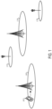
- FIG. 1 illustrates an example of portions of a cellular communication network.
- the network is a Universal Mobile Telecommunications System (UMTS) network.
- the network 100 can include macro cells 105, 110 that service larger areas and can include smaller cells 115, 120 that service smaller areas.
- FIG. 1 also illustrates user equipment (UE) 102 operating in the network.
- UE user equipment
- the UE 102 may be a portable wireless communication device, such as a personal digital assistant (PDA), a laptop or portable computer with wireless communication capability, a web tablet, a wireless telephone, a smartphone, a wireless headset, a pager, an instant messaging device, a digital camera, an access point, a television, a medical device (e.g., a heart rate monitor, a blood pressure monitor, etc.), or other device that may receive and/or transmit information wirelessly.
- PDA personal digital assistant
- laptop or portable computer with wireless communication capability such as a personal digital assistant (PDA), a laptop or portable computer with wireless communication capability, a web tablet, a wireless telephone, a smartphone, a wireless headset, a pager, an instant messaging device, a digital camera, an access point, a television, a medical device (e.g., a heart rate monitor, a blood pressure monitor, etc.), or other device that may receive and/or transmit information wirelessly.
- a medical device e.g., a heart rate monitor
- FIG. 2 illustrates a functional block diagram of UE for a cellular communication network.
- the UE may be suitable for use as any one or more of the UEs 102 illustrated in FIG. 1 .
- the UE may include physical layer (PHY) circuitry 203 for transmitting and receiving radio frequency electrical signals to and from one or more nodes of a radio access network using one or more antennas 201.
- the PHY circuitry 203 may include circuitry for modulation/demodulation, upconversion/downconversion, filtering, amplification, etc.
- the UE may also include medium access control layer (MAC) circuitry 204 for controlling access to the wireless medium and to configure frames or packets for communicating over the wireless medium.
- the UE may also include processing circuitry 206 and memory 208 arranged to configure the various elements of the UE to perform the operations described herein.
- the memory 208 may be used to store information for configuring the processing circuitry 206 to perform the operations.
- the UE is illustrated as having several separate functional elements, one or more of the functional elements may be combined and may be implemented by combinations of software-configured elements, such as processing elements including digital signal processors (DSPs), and/or other hardware elements.
- DSPs digital signal processors
- some elements may comprise one or more microprocessors, DSPs, application specific integrated circuits (ASICs), radio-frequency integrated circuits (RFICs), and combinations of various hardware and logic circuitry for performing at least the functions described herein.
- the functional elements may refer to one or more processes operating on one or more processing elements.
- Embodiments may be implemented in one or a combination of hardware, firmware and software. Embodiments may also be implemented as instructions stored on a computer-readable storage medium, which may be read and executed by at least one processor to perform the operations described herein.
- a computer-readable storage medium may include any non-transitory mechanism for storing information in a form readable by a machine (e.g., a computer).
- a computer-readable storage medium may include read-only memory (ROM), random-access memory (RAM), magnetic disk storage media, optical storage media, flash-memory devices, and other storage devices and media.
- one or more processors may be configured with the instructions to perform the operations described herein.
- the one or more antennas 201 utilized by the UE 200 may comprise one or more directional or omnidirectional antennas, including, for example, dipole antennas, monopole antennas, patch antennas, loop antennas, microstrip antennas or other types of antennas suitable for transmission of radio frequency (RF) signals.
- RF radio frequency
- the antennas instead of two or more antennas, a single antenna with multiple apertures may be used. In these embodiments, each aperture may be considered a separate antenna.
- MIMO multiple-input multiple-output
- the antennas may be effectively separated to take advantage of spatial diversity and the different channel characteristics that may result between each of antennas and the antennas of a transmitting station. In some MIMO embodiments, the antennas may be separated by up to 1/10 of a wavelength or more.
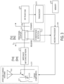
- FIG. 3 is a block diagram of portions of an embodiment of an RF communication device, such as UE for a cellular communication network for example.
- the device 300 includes an RF antenna circuit 301, an antenna aperture tuning circuit 310, and a processor circuit 306.
- the device 300 also includes an antenna impedance measurement circuit that includes a power phase and amplitude detector 312.
- Also shown in FIG. 3 are an impedance matching network 314 circuit, an RF transceiver 316, a directional coupler 318, and an RF front end 320.
- the RF front end 320 includes the RF filters used to reject an out of band signal when transmitting and receiving RF signals. As shown in FIG.
- the antenna aperture tuning circuit 310 can include or more RF switches 322 and can include one more tunable capacitors 324.
- the RF switches 322 can be coupled between a radiating element of the antenna 301 and a circuit component, such as one or more of an inductor, capacitor, another radiating element of the antenna, and circuit ground for example.
- the one or more tuning capacitors 324 can be coupled between a radiating element of the antenna 301 and either another radiating element of the antenna or a circuit ground.
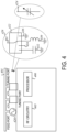
- FIG. 4 is a block diagram of portions of an embodiment of an antenna aperture tuning circuit 410.
- An antenna radiating element 401 is connected to RF circuitry 405 at feed port 426 and by one or more tuning ports 428 separate from the feed port 426.
- the RF circuitry 405 can include one or more of the RF circuitry blocks shown in FIG. 3 . As shown in detail in FIG.
- a tuning port 428 can include one or more of an inductor 430 coupled between the antenna radiating element 401 and circuit ground by an RF switch 422, a capacitor 432 coupled between the antenna radiating element 401 and circuit ground by an RF switch 422, at least a second antenna radiating element 434 coupled to the first antenna radiating element 401 by an RF switch 422, and a circuit ground 436 coupled to the antenna radiating element 401 by an RF switch 422.
- the tuning port includes a single-pole four-throw (SP4T) switch to connect the antenna radiating element 401 to one of the inductor 430, the capacitor 432, the second antenna radiating element 434, or the circuit ground 436.
- the tuning port 428 can include a different RF switch configuration to connect one or a combination of the inductor, the capacitor, the second radiating element and the circuit ground to the antenna radiating element 401.
- a processor 406 e.g., a modem processor
- the antenna aperture tuning state is changed by the processor 406 changing the configuration of the RF switch or switches.
- the antenna aperture tuning state is set using a tunable capacitor 424.
- the overall capacitance of a tunable capacitor can be adjusted or tuned or by adding or removing unit sized capacitors to the tunable capacitor circuit. In other variations, the overall capacitance could be tuned by changing the biasing voltage to the dielectric material of the capacitor.
- a tuning port 428 can include one or both of: the antenna radiating element 401 coupled to circuit ground by a tunable capacitor, and a second antenna radiating element coupled to the first antenna radiating element 401 by a tunable capacitor 424.
- the tunable capacitor could be replaced by a circuit consisting of a tunable capacitor connected in series with an inductor, connected in parallel with an inductor, or a combination of serial and parallel connections with one or more inductors.
- the processor 406 sets the antenna aperture tuning state by setting the capacitance value of one or more tunable capacitors of the tuning port or ports.
- the tuning ports 428 may include both RF switches and tuning capacitors.
- the antenna aperture tuning circuit 410 includes one or more tuning ports with a combination of components switchable to the antenna radiating element by one or more RF switches 422 and components electrically coupled to the antenna radiating element 401 by one or more tunable capacitors 424.
- the processor 406 changes the antenna aperture tuning state by changing the capacitance value of one or more tunable capacitors and activating/deactivating one or more RF switches.
- the desired antenna aperture tuning state is determined according to antenna impedance measured by the antenna impedance measurement circuit.
- the impedance measurement circuit measures the complex reflection coefficient ( ⁇ M ) at the reference plane.
- the impedance measurement circuit may include the power phase and amplitude detector 312.
- To measure antenna impedance an RF signal is transmitted and the forward signal and the reverse signal are extracted using the directional coupler 318. The amplitudes of the forward and reverse signals (or the ratio of the amplitudes of the forward and reverse signals), and the relative phase between the forward signal and reverse signal are measured.
- the complex reflection coefficient ( ⁇ M ) may be determined from the ratio of the amplitudes and the relative phase, and the impedance at the reference plane is derived using the reflection coefficient.
- the impedance matching network 314 may be de-embedded to derive the raw impedance ( ⁇ ANT ).
- the de-embedding could be analytical and completed in real-time or runtime using a current circuit model (or two-port network mathematical model) of the impedance matching network.
- the de-embedding may be implicit in a lookup table based implementation where the effect of the impedance matching network 314 may be predetermined and accounted for in the calculations.
- the detection circuit is a differential detection circuit and the simultaneously extracted forward and reverse signals are fed into the differential detection circuit to obtain a ratio of the amplitudes and the relative phase.
- the amplitude determinations for the forward and reverse signal are performed separately, and the ratio of the amplitudes is computed based on the detected values.
- the phase detection is realized by correlating the extracted forward/reverse signal with a transmit reference signal (or I/Q signal).
- the detected phase of each of the forward signal and the reverse signal are compared to obtain the relative phase between the forward signal and the reverse signal.
- the amplitude and phase detection could be realized in a discrete circuit implemented using one or both of analog and digital circuits, or the detection could be integrated into the RF transceiver utilizing the modem processor and completed in the digital domain.
- the processor circuit 306 changes the antenna aperture tuning state accordingly. This creates a closed loop control of antenna aperture state based on antenna impedance.
- a lookup table can be used to map the antenna aperture tuning states available to predetermined antenna impedances. The lookup table may be stored in a memory circuit 338 separate from, or integral to, the processor circuit 306.
- Table 1 below is an example of potions of a lookup table.
- antenna aperture tuning states that correspond to the present tuning state of the device. Included for each tuning state are multiple impedance ranges.
- the impedance ranges for Tuning State 1 are Impedance Range 11, Impedance Range 12, Impedance Range 13 ... Impedance Range 1 N .
- the impedance ranges for Tuning State 2 are Impedance Range 21, Impedance Range 22, Impedance Range 23 ... Impedance Range 2N.
- the impedance ranges for Tuning State N are Impedance Range N 1, Impedance Range N2, Impedance Range N 3 ... Impedance Range NN.
- the lookup table maps the present Tuning State and the determined antenna impedance to the desired tuning state.
- the lookup table may indicate that the present tuning state is the best tuning, or the lookup table may indicate that a different tuning state is the best tuning state. For instance, if the present tuning state is Tuning State 1 and the antenna impedance fall into impedance range 11, the lookup table indicates that Tuning State 1 is the best antenna aperture tuning state and the tuning state is not changed. If the present tuning state is Tuning State 1 and the antenna impedance fall into impedance range 13, the lookup table indicates that Tuning State 2 is the best antenna aperture tuning state and the tuning state is changed to Tuning State 2.
- the Tuning States of Table 1 may correspond to a configuration of RF switches, a configuration of settings for one or more tunable capacitors or tunable inductors, or any combination of RF switch configurations, capacitor configurations, and inductor configurations.
- the number of antenna aperture tuning states that can be configured may exceed the number of aperture tuning states that are actually usable or desirable.
- a Tuning State of Table 1 may be mapped to a specific circuit configuration, such as by using a lookup table for example. The mapping may be incorporated into a single lookup table that includes the impedance mapping or a separate lookup table can be specifically used for the configuration mapping.
- Table 2 below is an example of a lookup table to map Tuning States to actual circuit configurations.
- a Tuning State value is mapped to a row that includes a digital value that can be used to set the antenna aperture tuning state. For instance, assume the antenna aperture tuning state is determined by the SP4T RF switch 422 in FIG. 4 . The digital value can be used to set the position of the RF switch 422 to couple the antenna radiating element 401 to one of the inductor 430, the capacitor 432, the additional antenna radiating element 434, or the circuit ground 436.
- the entries of Table 2 may be incorporated into Table 1 by expanding the Tuning State rows to include the circuit configuration settings.
- the digital for the circuit configuration may be loaded and used to re-configure the antenna aperture tuning state.
- TABLE 2 Tuning State 1 1 0 0 0 2 0 1 0 0 3 0 0 1 0 4 0 0 0 1
- the example lookup tables are intended to be illustrative and non-limiting.
- the antenna aperture tuning state may include more configurable options resulting in more entries in the lookup table.
- each of the circuit components may be connectable to the antenna radiating element 401 by an individually controllable RF switch 422.
- the antenna aperture tuning circuit includes one or more tunable capacitors 424 as described previously herein, the digital value of a row of the lookup table can be used to set the capacitance value of the tunable capacitor.
- an equation or other means may be used to obtain the antenna aperture tuning state, but the lookup table is likely sufficient and effective for this purpose.
- the impedance matching network 314 may be tunable to provide a fine adjustment for the antenna.
- a tunable impedance matching network may include one or more of a tunable shunt capacitor coupled between an antenna radiating element and ground, a tunable capacitor serially coupled between radiating antenna elements, a tunable inductor coupled in serial or shunt configuration, and one or more RF switches coupled to a capacitor or inductor.
- the processor circuit 306 changes the impedance of the impedance matching circuit by changing one or more of a capacitance value of an tunable capacitor, an inductance value of a tunable inductor, and a state of one or more RF switches of the impedance matching circuit 314.
- the processor circuit 306 may adjust the impedance matching network 314 to optimize a figure of merit of the antenna, such as by tuning the impedance matching circuit to increase the transducer gain of the impedance matching circuit 314.
- the tuning by the processor circuit 306 can provide closed loop coarse tuning and closed loop fine tuning of the antenna circuit.
- the processor circuit 306 may continue to make the fine adjustments and continue to monitor the antenna raw impedance. When the antenna raw impedance changes to a new impedance value or a new impedance range that changes the entry in the lookup table, the processor circuit 306 loads and configures the new antenna aperture tuning state.
- FIG. 5 is a flow diagram of an embodiment of a method 500 of antenna aperture tuning for an RF communication device.
- an initial or current antenna aperture tuning state is set according to one or more parameters of the RF communication network.
- the network parameters include a radio access technology (RAT) of the RF communication network, a channel frequency band of the RF communication network, and bandwidth of the RF communication network.
- the antenna aperture tuning state can be set by configuring tunable capacitors, tunable inductors and RF switches as described previously.
- the next step is to determine the antenna impedance and determine whether the current antenna aperture tuning state is the best one suited for the measured impedance.
- a processor may recurrently initiate the measurement of antenna impedance according to a specified schedule. In some embodiments, the measurement of antenna impedance may be initiated when a parameter of the RF communication network changes.
- the antenna impedance can be measured using a forward signal and a reverse signal of a transmit signal, such as described previously.
- P Tx the power of the transmit signal
- the current aperture tuning state is maintained at 525 and the process waits until it is time for another antenna impedance measurement. If the transmit power satisfies the specified threshold power, at 530 the antenna impedance is derived, such as by determining the reflection coefficient from forward and reverse signals as described previously and deriving the antenna impedance using the reflection coefficient. At 535, the best antenna aperture tuning state is determined according to the measured antenna impedance, such as by using a lookup table. At 540, if the best antenna aperture tuning state is the same as the current antenna aperture tuning state according to the measured antenna impedance, the process returns to 510 to wait for the next antenna impedance measurement to be initiated.
- Which aperture is best may depend on the current use case of the device, such as whether the device is being used in free space (FS), beside the head (BH) of the user, beside the head and hand left side (BHHL), beside the head and hand right side (BHHR). Other reasons can cause the overall antenna radiating efficiency to become less than the efficient of another antenna aperture tuning state. If the best antenna aperture tuning state is different from the current antenna aperture tuning state, at 545 the current antenna aperture tuning state is changed to the determined best state. The process returns to 510 to wait for the next antenna impedance measurement to be initiated.
- FS free space
- BH head
- BHHL head and hand left side
- BHHR head and hand right side
- the RF communication device may include an impedance matching circuit that is tunable, such as by adjusting a tunable capacitor of the impedance matching circuit for example.
- Further aperture tuning may be performed with coarse aperture state tuning.
- the coarse aperture tuning states are realized by RF switches, while fine aperture tuning is realized using tunable capacitors or tunable inductors with fine tuning capability.
- a lookup table may be created for the coarse aperture tuning states, and the fine aperture tuning is realized by monitoring the reflection coefficient and by a comparison with a predetermined value for a desired figure of merit parameter.
- the figure of merit parameter can be used as feedback for adjustment of the capacitance value of the tunable capacitor by the processor.
- only fine tuning is included under closed loop control by a processor.
- An initial antenna aperture tuning state may be selected (e.g., by a lookup table) from a few coarse tuning states based on one or more operating parameters such as RAT, band, frequency and use case.
- the processor fine tunes one or more adjustable circuit components of the impedance matching circuit to optimize the figure of merit parameter.
- the fine tuning is realized by monitoring a reflection coefficient and adjusting the one or more circuit components to adjust the reflection coefficient toward a predetermined value.
- the several examples described provide solutions to optimize antenna efficiency for all frequency bands under changing conditions in which the RF device is used.
- the RF device accomplishes this by reconfiguring the antenna aperture in real time.
- An Example of an apparatus comprises a radio frequency (RF) antenna circuit; an antenna aperture tuning circuit; an antenna impedance measurement circuit; and a processor circuit electrically coupled to the tunable antenna aperture circuit and the impedance measurement circuit, wherein the processor circuit is configured to: set the antenna aperture tuning circuit to an antenna aperture tuning state according to one or more parameters of an RF communication network; initiate an antenna impedance measurement to obtain an antenna impedance; and adjust the antenna aperture tuning state as a function of the antenna impedance.
- RF radio frequency
- the apparatus includes an antenna aperture tuning circuit that includes one or more of: an inductor coupled to the RF antenna circuit by an RF switch, a capacitor coupled to the RF antenna circuit by an RF switch, at least a first antenna radiating element coupled to a second antenna radiating element by an RF switch, an antenna radiating element coupled to a circuit ground by an RF switch; and wherein the processor circuit is configured to set the antenna aperture tuning state by configuring one or more RF switches of the antenna aperture tuning circuit.
- the apparatus includes an antenna aperture tuning circuit that includes one or more of: at least a first antenna radiating element coupled to a second antenna radiating element by a tunable capacitor; and an antenna radiating element coupled to a circuit ground by a tunable capacitor; and wherein the processor circuit is configured to set the antenna aperture tuning state by setting the capacitance value of one or more tunable capacitors.
- the apparatus includes an impedance matching circuit electrically coupled to the RF antenna circuit, wherein the processor circuit is optionally configured to change impedance of the impedance matching circuit to change transducer gain of the RF antenna circuit when the antenna aperture tuning state is set to the antenna aperture tuning state indicated by the antenna impedance.
- the apparatus includes a memory circuit configured to store a lookup table that includes antenna aperture tuning states indexed according to antenna impedance, wherein the processor circuit is configured to set the antenna aperture tuning state using the lookup table.
- the apparatus includes an adjustable capacitor electrically coupled between one of a radiating element and circuit ground, or a first radiating element and a second radiating element, wherein the processor circuit is configured to set the antenna aperture tuning state by changing a capacitance value of the adjustable capacitor.
- the apparatus includes a transmit power measurement circuit configured to determine a measure of transmit power, and wherein the processor circuit is configured to initiate a measurement of transmit power, and initiate the antenna impedance measurement conditional upon the measurement of transmit power satisfying a specified measurement transmit power threshold.
- the apparatus includes an antenna impedance measurement circuit configured to determine magnitude and phase of a forward signal and a reverse signal of a transmit signal, and wherein the processor circuit is configured to determine the antenna impedance measurement using a difference in phase between the forward signal and the reverse signal, and a ratio including the magnitudes of the forward signal and the reverse signals.
- the apparatus includes a processor circuit configured to recurrently initiate the measurement of antenna impedance according to a specified schedule, and change the antenna aperture tuning state according to the determined antenna impedance.
- the apparatus includes a processor circuit configured to set the aperture tuning circuit to an antenna aperture tuning state and initiate the measurement of antenna impedance when detecting a change in the one or more parameters of the RF communication network.
- the apparatus includes a processor circuit configured to set the antenna aperture tuning circuit to an antenna aperture tuning state according to one or more parameters that include one or more of a radio access technology (RAT) of the RF communication network, a channel of the RF communication network, and bandwidth of the RF communication network.
- RAT radio access technology
- An Example of a computer readable storage medium includes instructions that when performed by processing circuitry of an RF communication device, cause the RF communication device to perform specified operations comprising setting an antenna aperture tuning state according to one or more parameters of the RF communication network; determining antenna impedance; and changing the antenna aperture tuning state according to the determined antenna impedance.
- the operations includes one or more of: changing an RF coupling state of a first antenna radiating element to a second radiating element, changing an RF coupling state of an antenna radiating element to ground, changing an RF coupling state of an antenna radiating element to an inductor of an antenna circuit of the RF circuitry, changing an RF coupling state of an antenna radiating element to a capacitor of the antenna circuit, and changing an RF coupling location of a ground leg of an RF antenna circuit of the RF circuitry.
- the operations include tuning an impedance matching circuit to change transducer gain of an RF antenna circuit of the RF circuitry in addition to changing the antenna aperture tuning state.
- the operations includes identifying an antenna aperture tuning state using a lookup table that includes specified antenna aperture tuning states indexed according to antenna impedance, and setting the antenna aperture tuning state to a specified antenna aperture tuning state identified using the lookup table.
- the operations includes setting the antenna aperture tuning state by adjusting a capacitance value of a capacitor, wherein the capacitor is electrically coupled between one of a radiating element and circuit ground, or a first radiating element and a second radiating element.
- the operations includes determining the magnitude of transmit power, wherein the determining antenna impedance is conditional upon the determined magnitude of transmit power satisfying a specified threshold magnitude value.
- the operations include determining magnitude and phase of a transmit signal from a forward direction and a reverse direction, and determining the antenna impedance using a difference in phase between the transmit signal in the forward direction and the reverse direction, and a ratio including the magnitudes of the transmit signal in the forward direction and the reverse direction.
- An Example of a machine-readable medium including instructions that, when performed by the machine, cause the machine to perform acts comprising setting an antenna aperture tuning state according to parameters of the RF communication network; determining antenna impedance; determining a figure of merit parameter for the antenna aperture tuning state using the antenna impedance; and changing the antenna aperture tuning state according to the figure of merit parameter.
- the acts includes a computer readable storage medium including instructions to cause processing circuitry of the RF communication device to select an antenna aperture tuning state using a lookup table that includes antenna aperture tuning states indexed according to antenna impedance, and set the antenna aperture tuning state to the selected antenna aperture tuning state.
- An Example can include, or can optionally be combined with any portion or combination of any portions of any one or more of the above Examples to include, subject matter that can include means for performing any one or more of the functions of the above Examples, or a machine-readable medium including instructions that, when performed by a machine, cause the machine to perform any one or more of the functions of the above Examples.
- Method examples described herein can be machine or computer-implemented at least in part. Some examples can include a computer-readable storage medium or machine-readable storage medium encoded with instructions operable to configure an electronic device to perform methods as described in the above examples.
- An implementation of such methods can include code, such as microcode, assembly language code, a higher-level language code, or the like. Such code can include computer readable instructions for performing various methods. The code may form portions of computer program products. The code can be tangibly stored on one or more volatile, non-transitory, or non-volatile tangible computer-readable media, such as during execution or at other times.
- tangible computer-readable storage media can include, but are not limited to, hard disks, removable magnetic disks, removable optical disks (e.g., compact disks and digital video disks), magnetic cassettes, memory cards or sticks, random access memories (RAMs), read only memories (ROMs), and the like.
Landscapes
- Physics & Mathematics (AREA)
- Electromagnetism (AREA)
- Engineering & Computer Science (AREA)
- Computer Networks & Wireless Communication (AREA)
- Signal Processing (AREA)
- Transceivers (AREA)
- Details Of Aerials (AREA)
- Transmitters (AREA)
- Variable-Direction Aerials And Aerial Arrays (AREA)
- Support Of Aerials (AREA)
Applications Claiming Priority (3)
| Application Number | Priority Date | Filing Date | Title |
|---|---|---|---|
| US15/167,279 US10312582B2 (en) | 2016-05-27 | 2016-05-27 | Closed loop aperture tunable antenna |
| PCT/CN2017/085578 WO2017202313A1 (en) | 2016-05-27 | 2017-05-23 | Closed loop aperture tunable antenna |
| EP17802159.8A EP3417511B1 (en) | 2016-05-27 | 2017-05-23 | Closed loop aperture tunable antenna |
Related Parent Applications (2)
| Application Number | Title | Priority Date | Filing Date |
|---|---|---|---|
| EP17802159.8A Division-Into EP3417511B1 (en) | 2016-05-27 | 2017-05-23 | Closed loop aperture tunable antenna |
| EP17802159.8A Division EP3417511B1 (en) | 2016-05-27 | 2017-05-23 | Closed loop aperture tunable antenna |
Publications (3)
| Publication Number | Publication Date |
|---|---|
| EP3965229A1 EP3965229A1 (en) | 2022-03-09 |
| EP3965229B1 true EP3965229B1 (en) | 2023-08-09 |
| EP3965229C0 EP3965229C0 (en) | 2023-08-09 |
Family
ID=60412123
Family Applications (2)
| Application Number | Title | Priority Date | Filing Date |
|---|---|---|---|
| EP21189365.6A Active EP3965229B1 (en) | 2016-05-27 | 2017-05-23 | Closed loop aperture tunable antenna |
| EP17802159.8A Active EP3417511B1 (en) | 2016-05-27 | 2017-05-23 | Closed loop aperture tunable antenna |
Family Applications After (1)
| Application Number | Title | Priority Date | Filing Date |
|---|---|---|---|
| EP17802159.8A Active EP3417511B1 (en) | 2016-05-27 | 2017-05-23 | Closed loop aperture tunable antenna |
Country Status (8)
| Country | Link |
|---|---|
| US (4) | US10312582B2 (cg-RX-API-DMAC10.html) |
| EP (2) | EP3965229B1 (cg-RX-API-DMAC10.html) |
| JP (1) | JP6828984B2 (cg-RX-API-DMAC10.html) |
| KR (1) | KR102079073B1 (cg-RX-API-DMAC10.html) |
| CN (2) | CN114865320B (cg-RX-API-DMAC10.html) |
| AU (2) | AU2017270872B2 (cg-RX-API-DMAC10.html) |
| RU (1) | RU2705661C1 (cg-RX-API-DMAC10.html) |
| WO (1) | WO2017202313A1 (cg-RX-API-DMAC10.html) |
Families Citing this family (38)
| Publication number | Priority date | Publication date | Assignee | Title |
|---|---|---|---|---|
| US9960791B2 (en) * | 2013-12-12 | 2018-05-01 | Ethertronics, Inc. | RF integrated circuit with tunable component and memory |
| US10177744B2 (en) * | 2014-10-30 | 2019-01-08 | Mediatek Singapore Pte. Ltd. | Wireless communication unit, integrated circuit and method for antenna tuning |
| US10312582B2 (en) | 2016-05-27 | 2019-06-04 | Futurewei Technologies, Inc. | Closed loop aperture tunable antenna |
| US10523292B2 (en) * | 2016-07-21 | 2019-12-31 | Motorola Mobility Llc | Closed loop tuning operation with antenna switching |
| KR102468231B1 (ko) | 2016-07-22 | 2022-11-18 | 삼성전자주식회사 | 무선 통신 시스템에서 안테나 임피던스 매칭 장치 및 방법 |
| US10355662B2 (en) * | 2016-12-06 | 2019-07-16 | Honeywell International Inc. | Impedance matching using tunable elements |
| US10560953B2 (en) * | 2017-02-20 | 2020-02-11 | Samsung Electronics Co., Ltd. | Antenna tuning devices and antenna tuning methods |
| CN110915226B (zh) * | 2017-11-21 | 2021-05-18 | 华为技术有限公司 | 天线、天线的控制方法及终端 |
| JP6760544B2 (ja) * | 2018-04-25 | 2020-09-23 | 株式会社村田製作所 | アンテナ装置及び通信端末装置 |
| US10736050B2 (en) | 2018-07-09 | 2020-08-04 | Honeywell International Inc. | Adjusting transmission power of an antenna based on an object causing path loss in a communication link |
| CN109167604B (zh) * | 2018-08-23 | 2020-07-03 | 珠海格力电器股份有限公司 | 一种天线自主调谐系统、调谐方法及其通信设备 |
| KR102573284B1 (ko) | 2018-09-19 | 2023-09-01 | 삼성전자주식회사 | 신호의 대역폭에 따라 안테나 설정을 변경하는 전자 장치 및 제어 방법 |
| US10855320B2 (en) * | 2018-09-27 | 2020-12-01 | Qualcomm Incorporated | Antenna aperture tuning |
| CN109713445A (zh) * | 2019-01-18 | 2019-05-03 | 环旭电子股份有限公司 | 无线通信装置 |
| EP3701863B1 (en) * | 2019-02-26 | 2025-12-24 | Polar Electro Oy | Cardiogram measurements |
| US11569858B2 (en) | 2020-01-13 | 2023-01-31 | Apple Inc. | Adaptive antenna tuning system |
| CN111370855B (zh) * | 2020-03-20 | 2021-07-20 | 维沃移动通信有限公司 | 一种天线结构及电子设备 |
| CN111931893B (zh) * | 2020-07-10 | 2023-12-26 | 菜鸟智能物流控股有限公司 | 一种射频标签 |
| US11438850B2 (en) | 2020-09-09 | 2022-09-06 | Samsung Electronics Co., Ltd. | Data-driven methods for look up table-free closed-loop antenna impedance tuning |
| CN114698404B (zh) * | 2020-10-28 | 2025-06-06 | 华为技术有限公司 | 一种天线调谐装置及方法 |
| RU2756097C1 (ru) * | 2021-03-24 | 2021-09-28 | Денис Андреевич Рублев | Цифровой детектор микронаушников |
| CN112928470A (zh) * | 2021-03-29 | 2021-06-08 | Oppo广东移动通信有限公司 | 天线组件及电子设备 |
| US11689053B2 (en) | 2021-07-28 | 2023-06-27 | Wiliot, LTD. | Techniques for tuning an antenna of an energy harvester |
| US11955814B2 (en) | 2021-07-28 | 2024-04-09 | Wiliot, LTD. | Measuring energy-charging rate of an energy harvester |
| US11901931B2 (en) * | 2021-09-09 | 2024-02-13 | Qualcomm Incorporated | Transmit diversity power leakage detection and filtering in antenna compensator power detector |
| US12512583B2 (en) * | 2021-09-23 | 2025-12-30 | Semtech Corporation | Proximity sensor for RF control |
| KR102577995B1 (ko) * | 2021-11-30 | 2023-09-13 | 전희석 | 고전력 적응형 rf 안테나 튜닝 스위치 |
| CN116390115B (zh) * | 2021-12-22 | 2026-07-17 | 维沃移动通信有限公司 | 感知、感知配置方法、装置及通信设备 |
| US12573760B2 (en) * | 2022-05-12 | 2026-03-10 | Qorvo Us, Inc. | Antenna tuning circuit |
| US12689927B2 (en) * | 2022-08-16 | 2026-07-21 | Mediatek Inc. | Mobile communication system and usage scenario determination method for the same |
| WO2024049321A1 (ru) * | 2022-09-01 | 2024-03-07 | Общество С Ограниченной Ответственностью "Рублефф Технолоджи" | Децентрализованный цифровой детектор микронаушников |
| US12519231B2 (en) | 2022-09-06 | 2026-01-06 | Apple Inc. | Electronic device having antenna tuners around connector |
| WO2024085500A1 (ko) * | 2022-10-18 | 2024-04-25 | 삼성전자 주식회사 | Rfic 및 rfic를 포함하는 전자 장치 및 전자 장치의 동작 방법 |
| CN115548682B (zh) * | 2022-11-30 | 2023-03-14 | 成都天锐星通科技有限公司 | 一种相控阵天线及电子设备 |
| US12700888B2 (en) * | 2022-12-08 | 2026-08-04 | Mediatek Inc. | Method for performing antenna tuning control of wireless transceiver device in wireless communications system, and associated apparatus |
| CN115775967B (zh) * | 2022-12-21 | 2023-12-12 | 小米汽车科技有限公司 | 天线阻抗匹配电路、方法、车辆、存储介质和芯片 |
| US12477483B2 (en) * | 2023-07-27 | 2025-11-18 | Qualcomm Incorporated | Coherent uplink MIMO |
| US12647092B2 (en) * | 2024-01-16 | 2026-06-02 | Mediatek Inc. | Method for creating usage scenario determination database and mobile communication system for the same |
Family Cites Families (36)
| Publication number | Priority date | Publication date | Assignee | Title |
|---|---|---|---|---|
| JPS5819502B2 (ja) | 1976-02-16 | 1983-04-18 | アイシン精機株式会社 | チルトハンドルの調整位置記憶装置 |
| JP2001102841A (ja) * | 1999-09-29 | 2001-04-13 | Matsushita Electric Ind Co Ltd | アンテナ付き情報処理装置 |
| US7689188B2 (en) * | 2006-09-29 | 2010-03-30 | Broadcom Corporation | Method and system for dynamically tuning and calibrating an antenna using antenna hopping |
| US8095085B2 (en) | 2007-06-08 | 2012-01-10 | Arizona Board Of Regents For And On Behalf Of Arizona State University | Automatic antenna tuning unit for software-defined and cognitive radio |
| CN101312354A (zh) * | 2008-05-30 | 2008-11-26 | 北京创毅视讯科技有限公司 | 天线匹配电路和天线匹配方法 |
| DE102008053296A1 (de) * | 2008-10-27 | 2010-04-29 | Atmel Automotive Gmbh | Schaltung für eine Schleifenantenne und Verfahren zur Abstimmung |
| US8781420B2 (en) * | 2010-04-13 | 2014-07-15 | Apple Inc. | Adjustable wireless circuitry with antenna-based proximity detector |
| JP5819502B2 (ja) | 2010-08-10 | 2015-11-24 | パイオニア株式会社 | インピーダンス整合装置及び制御方法 |
| CN102437835B (zh) | 2010-09-29 | 2016-09-28 | 宏达国际电子股份有限公司 | 移动通讯装置的阻抗匹配装置与方法 |
| US9379454B2 (en) | 2010-11-08 | 2016-06-28 | Blackberry Limited | Method and apparatus for tuning antennas in a communication device |
| US8594584B2 (en) | 2011-05-16 | 2013-11-26 | Blackberry Limited | Method and apparatus for tuning a communication device |
| CN103931051B (zh) | 2011-05-16 | 2016-10-26 | 黑莓有限公司 | 用于调谐通信设备的方法和装置 |
| US9054756B2 (en) | 2011-09-19 | 2015-06-09 | Qualcomm Incorporated | Adaptive tuning of an impedance matching circuit in a wireless device |
| JP2013117749A (ja) * | 2011-12-01 | 2013-06-13 | Panasonic Corp | タグ |
| KR101874892B1 (ko) * | 2012-01-13 | 2018-07-05 | 삼성전자 주식회사 | 소형 안테나 장치 및 그 제어방법 |
| US20130187828A1 (en) * | 2012-01-24 | 2013-07-25 | Ethertronics, Inc. | Tunable matching network for antenna systems |
| US9325062B2 (en) | 2012-01-24 | 2016-04-26 | Ethertronics, Inc. | High speed tunable matching network for antenna systems |
| US9190712B2 (en) | 2012-02-03 | 2015-11-17 | Apple Inc. | Tunable antenna system |
| US20130241800A1 (en) * | 2012-03-14 | 2013-09-19 | Robert W. Schlub | Electronic Device with Tunable and Fixed Antennas |
| GB2501487A (en) * | 2012-04-24 | 2013-10-30 | Renesas Mobile Corp | Multiple frequency antenna involving filter and impedance matching arrangements |
| EP3131157B1 (en) | 2012-07-17 | 2021-02-24 | NXP USA, Inc. | Antenna tuning for multiband operation |
| US20140071015A1 (en) * | 2012-09-12 | 2014-03-13 | Medtronic, Inc. | Trim algorithm for a medical device antenna |
| EP2722996B1 (en) * | 2012-10-22 | 2014-12-17 | BlackBerry Limited | Method and apparatus for radio frequency tuning utilizing a determined use case |
| US8897734B2 (en) | 2012-10-30 | 2014-11-25 | Ericsson Modems Sa | Standing wave ratio meter for integrated antenna tuner |
| US9276312B2 (en) | 2013-03-13 | 2016-03-01 | Intel Deutschland Gmbh | Antenna tuner control system using state tables |
| US9515384B2 (en) | 2013-09-03 | 2016-12-06 | Mediatek Inc. | Apparatus and method for setting antenna resonant mode of multi-port antenna structure |
| CN103490794B (zh) * | 2013-09-09 | 2015-04-22 | 熊猫电子集团有限公司 | 可变天调匹配网络结构电路 |
| US9985353B1 (en) * | 2013-09-30 | 2018-05-29 | Ethertronics, Inc. | Antenna system for metallized devices |
| US9287624B2 (en) * | 2013-10-21 | 2016-03-15 | Hong Kong Applied Science and Technology Research Institute Company Limited | Antenna circuit and a method of optimisation thereof |
| US20150116162A1 (en) * | 2013-10-28 | 2015-04-30 | Skycross, Inc. | Antenna structures and methods thereof for determining a frequency offset based on a differential magnitude |
| US9825364B2 (en) * | 2014-06-12 | 2017-11-21 | Verily Life Sciences Llc | Adaptive antenna tuning based on measured antenna impedance |
| US9444425B2 (en) | 2014-06-20 | 2016-09-13 | Apple Inc. | Electronic device with adjustable wireless circuitry |
| US9577318B2 (en) * | 2014-08-19 | 2017-02-21 | Apple Inc. | Electronic device with fingerprint sensor and tunable hybrid antenna |
| US20160126618A1 (en) * | 2014-10-29 | 2016-05-05 | Mediatek Singapore Pte. Ltd. | Integrated circuit, wireless communication unit, and method for antenna matching |
| US10177744B2 (en) * | 2014-10-30 | 2019-01-08 | Mediatek Singapore Pte. Ltd. | Wireless communication unit, integrated circuit and method for antenna tuning |
| US10312582B2 (en) | 2016-05-27 | 2019-06-04 | Futurewei Technologies, Inc. | Closed loop aperture tunable antenna |
-
2016
- 2016-05-27 US US15/167,279 patent/US10312582B2/en active Active
-
2017
- 2017-05-23 EP EP21189365.6A patent/EP3965229B1/en active Active
- 2017-05-23 EP EP17802159.8A patent/EP3417511B1/en active Active
- 2017-05-23 CN CN202210370528.2A patent/CN114865320B/zh active Active
- 2017-05-23 WO PCT/CN2017/085578 patent/WO2017202313A1/en not_active Ceased
- 2017-05-23 CN CN201780025378.9A patent/CN109121443B/zh active Active
- 2017-05-23 KR KR1020187029311A patent/KR102079073B1/ko active Active
- 2017-05-23 RU RU2018139492A patent/RU2705661C1/ru active
- 2017-05-23 AU AU2017270872A patent/AU2017270872B2/en active Active
- 2017-05-23 JP JP2018550465A patent/JP6828984B2/ja active Active
-
2019
- 2019-05-30 US US16/426,837 patent/US10637138B2/en active Active
-
2020
- 2020-03-18 US US16/822,881 patent/US10797387B2/en active Active
- 2020-07-23 AU AU2020207855A patent/AU2020207855B2/en active Active
- 2020-10-05 US US17/063,340 patent/US11211698B2/en active Active
Also Published As
| Publication number | Publication date |
|---|---|
| US20210135350A1 (en) | 2021-05-06 |
| JP6828984B2 (ja) | 2021-02-10 |
| AU2020207855B2 (en) | 2021-09-16 |
| RU2705661C1 (ru) | 2019-11-11 |
| KR102079073B1 (ko) | 2020-02-19 |
| KR20180117197A (ko) | 2018-10-26 |
| CN109121443A (zh) | 2019-01-01 |
| EP3417511A1 (en) | 2018-12-26 |
| EP3417511B1 (en) | 2021-09-08 |
| CN114865320A (zh) | 2022-08-05 |
| CN114865320B (zh) | 2025-04-01 |
| US10797387B2 (en) | 2020-10-06 |
| US20170346178A1 (en) | 2017-11-30 |
| JP2019514261A (ja) | 2019-05-30 |
| US11211698B2 (en) | 2021-12-28 |
| EP3417511A4 (en) | 2019-02-27 |
| AU2017270872B2 (en) | 2020-04-30 |
| WO2017202313A1 (en) | 2017-11-30 |
| US10312582B2 (en) | 2019-06-04 |
| AU2020207855A1 (en) | 2020-08-13 |
| US20200021018A1 (en) | 2020-01-16 |
| AU2017270872A1 (en) | 2018-10-11 |
| CN109121443B (zh) | 2022-04-22 |
| EP3965229A1 (en) | 2022-03-09 |
| US10637138B2 (en) | 2020-04-28 |
| EP3965229C0 (en) | 2023-08-09 |
| US20200220258A1 (en) | 2020-07-09 |
Similar Documents
| Publication | Publication Date | Title |
|---|---|---|
| US11211698B2 (en) | Closed loop aperture tunable antenna | |
| US9002278B2 (en) | Simple automatic antenna tuning system and method | |
| EP3329602B1 (en) | Calibration and adaptive control of antenna tuners | |
| EP2768147B1 (en) | Methods and apparatus for performing impedance matching | |
| EP3414837B1 (en) | Apparatus and method for impedance measurement and adaptive antenna tuning | |
| EP3188309A1 (en) | Method and apparatus for tuning a communication device | |
| US9698858B2 (en) | Method and apparatus for radio antenna frequency tuning | |
| JP6235130B2 (ja) | チューナブルumtsマルチバンドフィルタのためのバンドグループ化の組み合せ | |
| US11211911B2 (en) | Capacitive-coupled bandpass filter | |
| CN104852148A (zh) | 一种可调谐天线及终端 | |
| US9438279B2 (en) | Wireless device with adaptively-tunable electrically-small antennas | |
| WO2013148225A1 (en) | Method and apparatus for compensating for phase shift in a communication device | |
| Amin et al. | Tunable front-end design with a dual-band antenna for small cellular devices | |
| HK1201104B (en) | Methods and apparatus for performing impedance matching |
Legal Events
| Date | Code | Title | Description |
|---|---|---|---|
| PUAI | Public reference made under article 153(3) epc to a published international application that has entered the european phase |
Free format text: ORIGINAL CODE: 0009012 |
|
| STAA | Information on the status of an ep patent application or granted ep patent |
Free format text: STATUS: THE APPLICATION HAS BEEN PUBLISHED |
|
| AC | Divisional application: reference to earlier application |
Ref document number: 3417511 Country of ref document: EP Kind code of ref document: P |
|
| AK | Designated contracting states |
Kind code of ref document: A1 Designated state(s): AL AT BE BG CH CY CZ DE DK EE ES FI FR GB GR HR HU IE IS IT LI LT LU LV MC MK MT NL NO PL PT RO RS SE SI SK SM TR |
|
| STAA | Information on the status of an ep patent application or granted ep patent |
Free format text: STATUS: REQUEST FOR EXAMINATION WAS MADE |
|
| 17P | Request for examination filed |
Effective date: 20220909 |
|
| RBV | Designated contracting states (corrected) |
Designated state(s): AL AT BE BG CH CY CZ DE DK EE ES FI FR GB GR HR HU IE IS IT LI LT LU LV MC MK MT NL NO PL PT RO RS SE SI SK SM TR |
|
| GRAP | Despatch of communication of intention to grant a patent |
Free format text: ORIGINAL CODE: EPIDOSNIGR1 |
|
| STAA | Information on the status of an ep patent application or granted ep patent |
Free format text: STATUS: GRANT OF PATENT IS INTENDED |
|
| INTG | Intention to grant announced |
Effective date: 20230222 |
|
| GRAS | Grant fee paid |
Free format text: ORIGINAL CODE: EPIDOSNIGR3 |
|
| GRAA | (expected) grant |
Free format text: ORIGINAL CODE: 0009210 |
|
| STAA | Information on the status of an ep patent application or granted ep patent |
Free format text: STATUS: THE PATENT HAS BEEN GRANTED |
|
| AC | Divisional application: reference to earlier application |
Ref document number: 3417511 Country of ref document: EP Kind code of ref document: P |
|
| AK | Designated contracting states |
Kind code of ref document: B1 Designated state(s): AL AT BE BG CH CY CZ DE DK EE ES FI FR GB GR HR HU IE IS IT LI LT LU LV MC MK MT NL NO PL PT RO RS SE SI SK SM TR |
|
| REG | Reference to a national code |
Ref country code: GB Ref legal event code: FG4D |
|
| REG | Reference to a national code |
Ref country code: CH Ref legal event code: EP |
|
| REG | Reference to a national code |
Ref country code: IE Ref legal event code: FG4D |
|
| REG | Reference to a national code |
Ref country code: DE Ref legal event code: R096 Ref document number: 602017072695 Country of ref document: DE |
|
| U01 | Request for unitary effect filed |
Effective date: 20230809 |
|
| U07 | Unitary effect registered |
Designated state(s): AT BE BG DE DK EE FI FR IT LT LU LV MT NL PT SE SI Effective date: 20230818 |
|
| PG25 | Lapsed in a contracting state [announced via postgrant information from national office to epo] |
Ref country code: GR Free format text: LAPSE BECAUSE OF FAILURE TO SUBMIT A TRANSLATION OF THE DESCRIPTION OR TO PAY THE FEE WITHIN THE PRESCRIBED TIME-LIMIT Effective date: 20231110 |
|
| PG25 | Lapsed in a contracting state [announced via postgrant information from national office to epo] |
Ref country code: IS Free format text: LAPSE BECAUSE OF FAILURE TO SUBMIT A TRANSLATION OF THE DESCRIPTION OR TO PAY THE FEE WITHIN THE PRESCRIBED TIME-LIMIT Effective date: 20231209 |
|
| PG25 | Lapsed in a contracting state [announced via postgrant information from national office to epo] |
Ref country code: RS Free format text: LAPSE BECAUSE OF FAILURE TO SUBMIT A TRANSLATION OF THE DESCRIPTION OR TO PAY THE FEE WITHIN THE PRESCRIBED TIME-LIMIT Effective date: 20230809 Ref country code: NO Free format text: LAPSE BECAUSE OF FAILURE TO SUBMIT A TRANSLATION OF THE DESCRIPTION OR TO PAY THE FEE WITHIN THE PRESCRIBED TIME-LIMIT Effective date: 20231109 Ref country code: IS Free format text: LAPSE BECAUSE OF FAILURE TO SUBMIT A TRANSLATION OF THE DESCRIPTION OR TO PAY THE FEE WITHIN THE PRESCRIBED TIME-LIMIT Effective date: 20231209 Ref country code: HR Free format text: LAPSE BECAUSE OF FAILURE TO SUBMIT A TRANSLATION OF THE DESCRIPTION OR TO PAY THE FEE WITHIN THE PRESCRIBED TIME-LIMIT Effective date: 20230809 Ref country code: GR Free format text: LAPSE BECAUSE OF FAILURE TO SUBMIT A TRANSLATION OF THE DESCRIPTION OR TO PAY THE FEE WITHIN THE PRESCRIBED TIME-LIMIT Effective date: 20231110 |
|
| PG25 | Lapsed in a contracting state [announced via postgrant information from national office to epo] |
Ref country code: PL Free format text: LAPSE BECAUSE OF FAILURE TO SUBMIT A TRANSLATION OF THE DESCRIPTION OR TO PAY THE FEE WITHIN THE PRESCRIBED TIME-LIMIT Effective date: 20230809 |
|
| PG25 | Lapsed in a contracting state [announced via postgrant information from national office to epo] |
Ref country code: ES Free format text: LAPSE BECAUSE OF FAILURE TO SUBMIT A TRANSLATION OF THE DESCRIPTION OR TO PAY THE FEE WITHIN THE PRESCRIBED TIME-LIMIT Effective date: 20230809 |
|
| PG25 | Lapsed in a contracting state [announced via postgrant information from national office to epo] |
Ref country code: SM Free format text: LAPSE BECAUSE OF FAILURE TO SUBMIT A TRANSLATION OF THE DESCRIPTION OR TO PAY THE FEE WITHIN THE PRESCRIBED TIME-LIMIT Effective date: 20230809 Ref country code: RO Free format text: LAPSE BECAUSE OF FAILURE TO SUBMIT A TRANSLATION OF THE DESCRIPTION OR TO PAY THE FEE WITHIN THE PRESCRIBED TIME-LIMIT Effective date: 20230809 Ref country code: ES Free format text: LAPSE BECAUSE OF FAILURE TO SUBMIT A TRANSLATION OF THE DESCRIPTION OR TO PAY THE FEE WITHIN THE PRESCRIBED TIME-LIMIT Effective date: 20230809 Ref country code: CZ Free format text: LAPSE BECAUSE OF FAILURE TO SUBMIT A TRANSLATION OF THE DESCRIPTION OR TO PAY THE FEE WITHIN THE PRESCRIBED TIME-LIMIT Effective date: 20230809 Ref country code: SK Free format text: LAPSE BECAUSE OF FAILURE TO SUBMIT A TRANSLATION OF THE DESCRIPTION OR TO PAY THE FEE WITHIN THE PRESCRIBED TIME-LIMIT Effective date: 20230809 |
|
| REG | Reference to a national code |
Ref country code: DE Ref legal event code: R097 Ref document number: 602017072695 Country of ref document: DE |
|
| PLBE | No opposition filed within time limit |
Free format text: ORIGINAL CODE: 0009261 |
|
| STAA | Information on the status of an ep patent application or granted ep patent |
Free format text: STATUS: NO OPPOSITION FILED WITHIN TIME LIMIT |
|
| U20 | Renewal fee for the european patent with unitary effect paid |
Year of fee payment: 8 Effective date: 20240531 |
|
| 26N | No opposition filed |
Effective date: 20240513 |
|
| REG | Reference to a national code |
Ref country code: CH Ref legal event code: PL |
|
| PG25 | Lapsed in a contracting state [announced via postgrant information from national office to epo] |
Ref country code: MC Free format text: LAPSE BECAUSE OF FAILURE TO SUBMIT A TRANSLATION OF THE DESCRIPTION OR TO PAY THE FEE WITHIN THE PRESCRIBED TIME-LIMIT Effective date: 20230809 |
|
| PG25 | Lapsed in a contracting state [announced via postgrant information from national office to epo] |
Ref country code: MC Free format text: LAPSE BECAUSE OF FAILURE TO SUBMIT A TRANSLATION OF THE DESCRIPTION OR TO PAY THE FEE WITHIN THE PRESCRIBED TIME-LIMIT Effective date: 20230809 Ref country code: CH Free format text: LAPSE BECAUSE OF NON-PAYMENT OF DUE FEES Effective date: 20240531 |
|
| PG25 | Lapsed in a contracting state [announced via postgrant information from national office to epo] |
Ref country code: IE Free format text: LAPSE BECAUSE OF NON-PAYMENT OF DUE FEES Effective date: 20240523 |
|
| U20 | Renewal fee for the european patent with unitary effect paid |
Year of fee payment: 9 Effective date: 20250602 |
|
| PG25 | Lapsed in a contracting state [announced via postgrant information from national office to epo] |
Ref country code: CY Free format text: LAPSE BECAUSE OF FAILURE TO SUBMIT A TRANSLATION OF THE DESCRIPTION OR TO PAY THE FEE WITHIN THE PRESCRIBED TIME-LIMIT; INVALID AB INITIO Effective date: 20170523 |
|
| PG25 | Lapsed in a contracting state [announced via postgrant information from national office to epo] |
Ref country code: HU Free format text: LAPSE BECAUSE OF FAILURE TO SUBMIT A TRANSLATION OF THE DESCRIPTION OR TO PAY THE FEE WITHIN THE PRESCRIBED TIME-LIMIT; INVALID AB INITIO Effective date: 20170523 |
|
| PGFP | Annual fee paid to national office [announced via postgrant information from national office to epo] |
Ref country code: GB Payment date: 20260325 Year of fee payment: 10 |
|
| PG25 | Lapsed in a contracting state [announced via postgrant information from national office to epo] |
Ref country code: TR Free format text: LAPSE BECAUSE OF FAILURE TO SUBMIT A TRANSLATION OF THE DESCRIPTION OR TO PAY THE FEE WITHIN THE PRESCRIBED TIME-LIMIT Effective date: 20230809 |
|
| U20 | Renewal fee for the european patent with unitary effect paid |
Year of fee payment: 10 Effective date: 20260601 |