EP3965129B1 - Schaltelementführung - Google Patents
Schaltelementführung Download PDFInfo
- Publication number
- EP3965129B1 EP3965129B1 EP21190551.8A EP21190551A EP3965129B1 EP 3965129 B1 EP3965129 B1 EP 3965129B1 EP 21190551 A EP21190551 A EP 21190551A EP 3965129 B1 EP3965129 B1 EP 3965129B1
- Authority
- EP
- European Patent Office
- Prior art keywords
- switching element
- guide
- side member
- tab
- spring
- Prior art date
- Legal status (The legal status is an assumption and is not a legal conclusion. Google has not performed a legal analysis and makes no representation as to the accuracy of the status listed.)
- Active
Links
Images


Classifications
-
- H—ELECTRICITY
- H01—ELECTRIC ELEMENTS
- H01H—ELECTRIC SWITCHES; RELAYS; SELECTORS; EMERGENCY PROTECTIVE DEVICES
- H01H3/00—Mechanisms for operating contacts
- H01H3/32—Driving mechanisms, i.e. for transmitting driving force to the contacts
- H01H3/38—Driving mechanisms, i.e. for transmitting driving force to the contacts using spring or other flexible shaft coupling
-
- H—ELECTRICITY
- H01—ELECTRIC ELEMENTS
- H01H—ELECTRIC SWITCHES; RELAYS; SELECTORS; EMERGENCY PROTECTIVE DEVICES
- H01H1/00—Contacts
- H01H1/12—Contacts characterised by the manner in which co-operating contacts engage
- H01H1/14—Contacts characterised by the manner in which co-operating contacts engage by abutting
- H01H1/20—Bridging contacts
- H01H1/2008—Facilitate mounting or replacing contact bridge and pressure spring on carrier
-
- H—ELECTRICITY
- H01—ELECTRIC ELEMENTS
- H01H—ELECTRIC SWITCHES; RELAYS; SELECTORS; EMERGENCY PROTECTIVE DEVICES
- H01H13/00—Switches having rectilinearly-movable operating part or parts adapted for pushing or pulling in one direction only, e.g. push-button switch
- H01H13/02—Details
- H01H13/12—Movable parts; Contacts mounted thereon
- H01H13/14—Operating parts, e.g. push-button
-
- H—ELECTRICITY
- H01—ELECTRIC ELEMENTS
- H01H—ELECTRIC SWITCHES; RELAYS; SELECTORS; EMERGENCY PROTECTIVE DEVICES
- H01H1/00—Contacts
- H01H1/12—Contacts characterised by the manner in which co-operating contacts engage
- H01H1/14—Contacts characterised by the manner in which co-operating contacts engage by abutting
- H01H1/20—Bridging contacts
- H01H1/2075—T-shaped bridge; bridging contact has lateral arm for mounting resiliently or on a pivot
-
- H—ELECTRICITY
- H01—ELECTRIC ELEMENTS
- H01H—ELECTRIC SWITCHES; RELAYS; SELECTORS; EMERGENCY PROTECTIVE DEVICES
- H01H1/00—Contacts
- H01H1/12—Contacts characterised by the manner in which co-operating contacts engage
- H01H1/14—Contacts characterised by the manner in which co-operating contacts engage by abutting
- H01H1/20—Bridging contacts
- H01H1/2083—Bridging contact surfaces directed at an oblique angle with respect to the movement of the bridge
-
- H—ELECTRICITY
- H01—ELECTRIC ELEMENTS
- H01H—ELECTRIC SWITCHES; RELAYS; SELECTORS; EMERGENCY PROTECTIVE DEVICES
- H01H1/00—Contacts
- H01H1/50—Means for increasing contact pressure, preventing vibration of contacts, holding contacts together after engagement, or biasing contacts to the open position
-
- H—ELECTRICITY
- H01—ELECTRIC ELEMENTS
- H01H—ELECTRIC SWITCHES; RELAYS; SELECTORS; EMERGENCY PROTECTIVE DEVICES
- H01H13/00—Switches having rectilinearly-movable operating part or parts adapted for pushing or pulling in one direction only, e.g. push-button switch
- H01H13/02—Details
- H01H13/04—Cases; Covers
-
- H—ELECTRICITY
- H01—ELECTRIC ELEMENTS
- H01H—ELECTRIC SWITCHES; RELAYS; SELECTORS; EMERGENCY PROTECTIVE DEVICES
- H01H9/00—Details of switching devices, not covered by groups H01H1/00 - H01H7/00
- H01H9/02—Bases, casings, or covers
-
- H—ELECTRICITY
- H01—ELECTRIC ELEMENTS
- H01H—ELECTRIC SWITCHES; RELAYS; SELECTORS; EMERGENCY PROTECTIVE DEVICES
- H01H2221/00—Actuators
- H01H2221/024—Transmission element
-
- H—ELECTRICITY
- H01—ELECTRIC ELEMENTS
- H01H—ELECTRIC SWITCHES; RELAYS; SELECTORS; EMERGENCY PROTECTIVE DEVICES
- H01H9/00—Details of switching devices, not covered by groups H01H1/00 - H01H7/00
- H01H9/30—Means for extinguishing or preventing arc between current-carrying parts
- H01H9/34—Stationary parts for restricting or subdividing the arc, e.g. barrier plate
Definitions
- the subject matter disclosed herein relates to a switching device including a mechanical switching element which physically moves within a chamber between a closed and an open position. More specifically, a guide for the switching element is disclosed, which acts to retain the switching element in a desired physical orientation within the chamber.
- switching devices are components in an electrical circuit that may be controlled between an "ON" and an "OFF" state.
- the switching device In the ON state, the switching device establishes an electrical connection between contacts and allows electrical current to flow through the switching device from a power source to an electrical load.
- the switching device breaks the electrical connection between contacts, preventing the electrical current from flowing through the switching device.
- Switching devices may be used, for example, as a circuit breaker, motor protection device, contactor to supply power to one or more branch circuits, or the like.
- the switching device may be manually or automatically actuated.
- a mechanical switch or electronic actuator is provided which moves between two states. In one state, the mechanical switch or electronic actuator causes the switching device to establish the electrical connection, and, in the other state, the mechanical switch or electronic actuator causes the switching device to break the electrical connection.
- the mechanical switch or electronic actuator will cause a plunger to move a switching element within the switching device in a first direction as the switch or actuator transition from a first state to a second state.
- a spring causes the switching element to return to its original position.
- the switching element moves within a channel defined within the switching device.
- switching devices are not without certain challenges.
- the force of the switching element impacting the other contact to close the circuit may cause a small amount of recoil.
- the force applied by the spring may weaken, such that the spring does not immediately hold the switching element against the contact when closing the circuit.
- the switching element is no longer mechanically held between the plunger and the spring in its desired orientation within the channel.
- the switching element may move side-to-side, front-to-back, or even rotate within the channel. Movement of the switching element may, at a minimum, reduce the surface area of contacts that establish a physical connection, accelerating wear between contacts, or, in a worst case, cause failure of the switching device.
- Potential movement of the switching element within the switching device is not limited to normal wear of the switching device.
- a control circuit that is not yet operating correctly may cause a rapid cycling of state in the switching device between the ON and OFF states. This rapid cycling may simulate a bounce condition, where the plunger and spring are not always holding the switching element in place and the switching element may move or rotate within the channel.
- a sharp force applied to the housing of the switching element for example, during transport, may cause a vibration or impulse force to the device during which the spring compresses enough for the switching element to move or rotate within the channel. Such a force received by the switching device during shipping may result in premature failure of the device.
- SE 462 409 B relates to an electrical coupler. It describes a power-limiting electrical coupler with two series-connected break positions comprising two fixed contacts arranged on a contact-breaker frame at a distance from each other and a contact bridge arranged to connect the fixed contacts which is supported by a movable contact carrier for transverse movement of the contact bridge between an on and off position.
- the contact bridge is movable relative to the contact carrier under the influence of a contact pressure spring mounted in the contact carrier.
- a plastic guide device fixed to the contact bridge is designed with guide surfaces which for relative movement between the contact bridge and the contact carrier slide along corresponding guide surfaces on the contact carrier for parallel guidance of the movement of the contact bridge.
- FR 2 614 728 A1 relates to a contact-holder with translational displacement. It consists of an insulating support drilled with rectangular apertures spaced apart side by side and into each of which is fitted transversely a moving contact bridge held up by a long compression spring and intended to cooperate with an associated alignment of fixed contacts, provision is made for arranging, in each aperture, a U-shaped sliding clip whose bottom bears between the moving contact bridge and the spring, and whose side walls form guides for the spring during the repulsion of the contacts as well as skirts for protecting the spring against spray from metal vapours when an electrical arc appears at the time of repulsion.
- US 6 556 110 B1 relates to an arcing chamber assembly having two side walls, a contact compression spring, a contact link, a slide which can be mounted one behind the other in the interior of the arcing chamber assembly, just by stacking them from one side.
- the arcing chamber assembly includes a passage, whose length is at least equal to the length of the contact link on the component supply side.
- US 2014/224629 A1 relates to a contact slider unit for a switching unit, in particular for a circuit breaker, having a contact slider and a contact piece.
- a stabilizing element preventing bridge rotation is arranged on the contact piece.
- a guide for a switching element includes a front member, a rear member, a first side member, and a second side member.
- the front member is configured to extend longitudinally along a front side of the switching element
- the rear member is configured to extend longitudinally along a rear side of the switching element.
- the front member includes a first seat configured to receive a lower surface of the switching element and a first tab configured to retain the switching element within the guide.
- the rear member includes a second seat configured to receive the lower surface of the switching element and a second tab configured to retain the switching element within the guide.
- the first side member has a front edge and a rear edge, where the first side member extends between a first end of a lower portion of the front member and a first end of a lower portion of the rear member.
- the second side member has a front edge and a rear edge, where the second side member extends between a second end of the lower portion of the front member and a second end of the lower portion of the rear member.
- the first side member includes a first guide portion protruding outward from the front edge of the first side member and a second guide portion protruding outward from the rear edge of the first side member.
- the second side member incudes a third guide portion protruding outward from the front edge of the second side member, and a fourth guide portion protruding outward from the rear edge of the second side member.
- An opening is defined between the first side member and the second side member, where the opening is configured to receive a spring between the first and second side members. The spring engages the lower surface of the switching element, the lower portion of the front member, and the lower portion of the rear member when it is inserted into the opening.
- a switching device includes a plunger, a spring, a switching element, and a guide for the switching element.
- the plunger is configured to move reciprocally along an axis between a first position and a second position, and the spring is configured to be selectively compressed as the plunger is moved reciprocally along the axis.
- the switching element is positioned between the plunger and the spring.
- the spring is seated, at least in part, against the switching element, and the switching element receives a force applied by the spring in a direction toward the plunger.
- the guide includes an upper portion defining a seat for the switching element, at least one tab located on the upper portion, and a lower portion defining an opening in which an end of the spring is seated.
- the at least one tab is configured to retain the switching element within the guide, and the end of the spring is seated in part against the switching element and in part against the guide.
- the guide for a switching element includes an upper portion, a lower portion, and at least two tabs located on the upper portion.
- the upper portion defines a seat for the switching element, and the tabs are configured to retain the switching element within the guide.
- the lower portion defines an opening in which an end of a spring is seated, where the end of the spring is seated in part against the switching element and in part against the guide.
- the subject matter disclosed herein describes an improved switching device in which undesired movement of the switching element is reduced.
- the switching device may be, for example, a circuit breaker, a motor protection circuit, an electrical contactor, or the like.
- the switching device includes a manual or automatic actuator that causes a plunger to move reciprocally along an axis between a first position and a second position, where the first and second positions define an "On" and an "Off" position for the switching device.
- the switching device also includes a spring to be selectively compressed as the plunger moves reciprocally along the axis.
- a switching element is positioned between the plunger and the spring, where the spring is seated, at least in part, against the switching element. The spring is at least partially compressed in both the first and the second positions and applies a force against the switching element in the direction of the plunger.
- the guide includes an upper portion configured to receive the switching element and a lower portion configured to receive the spring.
- the upper portion includes a front member and a rear member, where the front and rear members each include a portion of a seat to receive the switching element.
- the front and rear members each include a resilient tab, where the resilient tab is configured to deflect outward as the switching element is inserted between the tabs on the front and rear members and to return to their original locations when the switching element is located in the seat of the guide to retain the switching element within the guide.
- the lower portion includes a first side member and a second side member.
- the first side member extends between a first side of a lower portion of the front and rear members
- the second side member extends between a second side of the lower portion of the front and rear members.
- the front member, rear member, first side member, and second side member are each made from a plastic material and integrally formed as a single mechanical element
- the guide includes guide portions configured to engage a housing on the switching device to prevent rotation of the switching element within the switching device.
- Guide portions protrude outward from front edges of the first and second side members to engage complementary channels extending along a first side of a housing for the switching device.
- Guide portions also protrude outward from rear edges of the first and second side members to engage complementary channels extending along a second side of a housing for the switching device.
- the guide portions slide within the channels of the housing. If the spring were to temporarily disengage the switching element due, for example, to vibration or a spring bounce, the guide portions prevent rotation of the switching element within the housing.
- the switching element further includes protrusions configured to engage the guide and to prevent longitudinal movement of the switching element within the housing.
- a pair of protrusions extend from each side of the switching element and are spaced apart a distance generally equal to the width of the guide.
- the guide is mounted on the switching element, the guide is positioned between the protrusions on each side of the switching element. If the spring were to temporarily disengage from the switching element, the protrusions engaging the guide, prevent the switching element from moving in the longitudinal direction of the switching element.
- the channels in the side of the housing may have a width generally equal to the width of the guide portions, such that the guide portions may also restrict movement in the longitudinal direction in addition to preventing rotation of the switching element.
- a switching device 10 that may be incorporated into an electrical switch, such as a circuit breaker, a motor protection circuit, an electrical contactor, or the like is illustrated.
- the switching device 10 includes a plunger 14 configured to move reciprocally, back-and-forth, along an axis 12.
- a first end 16 of the plunger 14 is configured to engage an actuator in the electrical switch.
- the actuator may be manually activated by, for example, a toggle switch or a rotary switch.
- the actuator may be automatically activated, for example, by a solenoid energized by a relay. Regardless of manual or automatic actuation, the plunger 14 is configured to move between a first position and a second position.
- the second end 18 of the plunger 14 (see e.g., Fig. 6 ) is configured to be inserted into a plunger seat 15.
- the plunger seat 15 may have a lower surface against which the second end 18 of the plunger 14 rests.
- the plunger seat 15 may have an open end and the plunger seat 15 is configured to align the plunger with the switching element 30.
- the second end 18 of the plunger 14 may then rest against the switching element 30.
- the plunger 14 applies a force to the switching element 30 when the actuator drives the plunger from the first position to the second position either directly if the second end 18 rests on the switching element 30 or indirectly via the plunger seat 15 if the plunger seat 15 includes a lower surface.
- the switching device 10 includes a spring 20 which applies a force, F, in a direction opposing actuation of the plunger 14.
- the spring 20 has a first end 22 which is seated against a lower housing of the switching device 10 and a second end 24 which is seated, at least in part, against a lower surface 31 of the switching element 30.
- the spring 20 may be partially compressed such that it applies a sufficient force against the switching element 30 to stay in the first position.
- the spring becomes more compressed, applying a greater force against the switching element 30.
- the spring 20 causes the switching element 30 to return to and stay in the first position.
- the switching element 30 is an assembly that includes at least one contact 38 mounted on the switching element 30.
- the contact 38 is configured to engage a complementary contact in the first position and to disengage from the complementary contact as the switching element 30 is moved from the first position to the second position.
- the switching element 30 includes a pair of contacts 38 where one contact is mounted to the switching element on one side of the plunger 14 when the plunger engages the switching element and the other contact is mounted on the other side of the plunger 14. It is contemplated that other arrangements of contacts 38 may be mounted to the switching element without deviating from the scope of the invention.
- the illustrated switching device 10 has a longitudinal form, where a length, L, of the switching element 30 is greater than a width, W, of the switching device.
- the switching device 10 includes a housing 50, where the housing has a first side 52 and a second side 54, the second side opposite the first side.
- a switching element channel 60 is defined, at least in part, by the housing 50 of the switching device 10.
- the switching element channel 60 has a first end 62 proximate one end of the switching device 10 and a second end 64 proximate another end of the switching device 10.
- the switching element channel 60 has a sectional area greater than the switching element 30 such that the switching element is free to move within the switching element channel.
- a first end 32 of the switching element 30 is located in the first end 62 of the switching element channel 60, and a second end 34 of the switching element 30 is located in the second end 64 of the switching element channel 60.
- a switching element guide 100 mounts on the switching element 30 and is configured to align the switching element 30 and to prevent undesired movement of the switching element within the switching element channel 60.
- the switching element guide 100 includes at least one guide portion protruding from the guide, the guide portion configured to engage a channel 55 in the housing 50 of the switching element.
- the front and rear of the switching element guide 100 each include a pair of guide portions.
- the first side 52 of the housing includes a pair of channels 55 extending along an interior surface of the housing, and the second side 54 of the housing similarly includes a pair of channels 55 extending along an interior surface. As the switching element 30 moves between the first and second positions, the guide portions slidably engage the channels 55 in the housing 50.
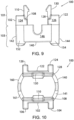
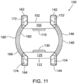
- Figs. 7-11 one embodiment of the switching element guide 100 is illustrated.
- the illustrated switching element guide 100 will be described with respect to an upper portion 101 and a lower portion 103. It is contemplated that the two portions may both be made from a plastic material and integrally formed as a single element.
- portions of the guide 100 may be made from separate portions and joined by any suitable method, such as by a fastener, an adhesive, thermal welding, ultrasonic welding, and the like.
- the upper portion 101 of the illustrated switching element guide 100 includes a front member 102 and a rear member 122.
- the front member 102 is configured to extend longitudinally along a front side 35 of the switching element 30 when the guide 100 is mounted to the switching element.
- the front member 102 extends between a first end 104 and a second end 106 and includes a seat 108 extending along an inner surface of the front member.
- the seat 108 is configured to receive a lower surface 31 of the switching element 30 when the guide 100 is fit onto the switching element 30.
- a tab 110 extends upward from the front member 102 and is configured to retain the switching element 30 within the guide 100 when the guide is fit onto the switching element.
- the rear member 122 is configured to extend longitudinally along a rear side 37 of the switching element 30 when the guide 100 is mounted to the switching element.
- the rear member 122 extends between a first end 124 and a second end 126 and includes a seat 128 extending along an inner surface of the rear member.
- the seat 128 is configured to receive a lower surface 31 of the switching element 30 when the guide 100 is fit onto the switching element 30.
- a tab 130 extends upward from the rear member 122 and is configured to retain the switching element 30 within the guide 100 when the guide is fit onto the switching element.
- the lower portion 103 of the illustrated switching element guide 100 includes a first side member 140 and a second side member 160.
- the first side member 140 includes a front edge 142 and a rear edge 144.
- An upper edge 141 of the first side member 140 extends between the front edge 142 and the rear edge 144.
- the upper edge 141 of the first side member 140 engages a lower portion 105 of a first end 104 of the front member 102 and a lower portion 125 of a first end 124 of the rear member 122.
- the first side member 140 includes a first guide portion 152 protruding from the front of the guide 100 and a second guide portion 154 protruding from the rear of the guide.
- the first and second guide portions 152, 154 extend upward onto the upper portion 101 of the guide 100.
- the first guide portion 152 extends onto the first end 104 of the front member 102 and the second guide portion 154 extends upward onto the first end 124 of the rear member 122.
- the guide portions 152, 154 may be located only on the lower portion 103 or only on the upper portion 101 of the guide.
- the second side member 160 includes a front edge 162 and a rear edge 164. An upper edge 161 of the second side member 160 extends between the front edge 162 and the rear edge 164.
- the upper edge 161 of the second side member 1 60 engages a lower portion 105 of a second end 106 of the front member 102 and a lower portion 125 of a second end 126 of the rear member 122.
- the second side member 160 includes a first guide portion 172 protruding from the front of the guide 100 and a second guide portion 174 protruding from the rear of the guide. According to the illustrated embodiment, the first and second guide portions 172, 174 extend upward onto the upper portion 101 of the guide 100. The first guide portion 172 extends onto the second end 106 of the front member 102 and the second guide portion 174 extends upward onto the second end 126 of the rear member 122.
- the guide portions 172, 174 may be located only on the lower portion 103 or only on the upper portion 101 of the guide. If the guide 100 is integrally formed as a single plastic member, it is contemplated that the upper edges 141, 161 of the first and second side members 140, 160 are joined to the lower portions 105, 125 of the front and rear members 102, 122.
- the switching element guide 100 positively retains the switching element 30 in a desired orientation within the switching device 10 and prevents undesired movement of the switching element.
- the switching element guide 100 is fit onto the switching element 30.
- the switching element 30 may be press fit between the first tab 110 and the second tab 130 extending upward from the front member 102 and from the rear member 122.
- the first and second tabs 110, 130 are made from a resilient material and are deflected outwards as the switching element 30 is fit between the two tabs.
- the tabs return to their original position and help retain the switching element 30 within the guide 100.
- the switching element 30 rests on the first and second seats 108, 128 of the front and rear members 102, 122.
- the switching element 30 may also include protrusions 36 configured to position the switching element guide 100 on the switching element and to help retain the positioning of the guide 100 with respect to the switching element 30.
- a pair of protrusions 36 extend laterally outward from the sides of the switching element.
- a first protrusion 36A and a second protrusion 36B form a pair of protrusions extending toward the first side 52 of the housing from the front side 35 of the switching element 30.
- a first protrusion 36A and a second protrusion 36B similarly form a pair of protrusions extending toward the second side 54 of the housing from the rear side 37 of the switching element 30.
- the first protrusion 36A and the second protrusion 36B are spaced apart a distance sufficient to receive the guide 100 between the two protrusions.
- the switching element guide 100 and the switching element 30 are positioned over the spring 20 in the switching device 10.
- An opening 180 is defined between the first side member 140 and the second side member 160 in which the spring 20 fits.
- the first end 22 of the spring 20 fits in the opening 180 and rests in part against the switching element 30 and in part against the lower portions 105, 125 of the front and rear members 102, 122.
- the first and second side members 140, 160 restrict lateral motion of the guide 100 beyond the spring 20 seated in the opening 180.
- the guide 100 in turn, restricts lateral motion of the switching element 30 seated within the guide.
- the guide portions 152, 154, 172, 174 engage the channels 55 on the housing 50 to further assist in retaining a desired orientation of the switching element 30.
- the front guide portions 152, 172 protruding from the front edges 142, 162 of the first and second side members 140, 160, respectively, engage channels 55 extending along an interior surface of the first side 52.
- the rear guide portions 154, 174 protruding from the rear edges 144, 164 of the first and second side members 140, 160, respectively, engage channels 55 extending along an interior surface of the second side 54.
- the guide portions 152, 154, 172, 174 slide within the channels 55 of the housing 50 are similarly driven in a direction parallel to the axis 12 along which the plunger travels. If, for example, the axis 12 is in a vertical direction and the plunger travels up-and-down, the guide portions 152, 154, 172, 174 similarly travel up-and-down within the channels 55.
- the guide portions prevent rotation of the switching element 30 either longitudinally or laterally. Preventing longitudinal rotation helps both contacts 38 on the switching element 30 make contact with and break apart from the corresponding contact within the switching device 10 in tandem.
- Preventing lateral rotation of the switching element 30 eliminates a failure mode of the switching device 10 discussed above. Specifically, if the switching element is subject to rapid switching or experiences a vibration or impulse force of sufficient magnitude such that the spring 20 and plunger 14 are no longer actively engaging both sides of the switching element 30, without the guide 100, the failure mode allowed the switching element 30 to rotate within the switching device 10 such that it was either perpendicular to its original orientation or it flipped over entirely and the contacts 38 on the switching element were facing away from the complementary contacts in the switching device 10. With the switching element guide 100 present on the switching element, the guide portions 152, 154, 172, 174 engage the sides 52, 54 of the housing 50 and prevent rotation of the switching element 30.
- the guide portions 152, 154, 172, 174 assist in aligning the contacts 38 on the switching element 30 with the complementary contacts in the switching device.
- the switching element guide 100 resists longitudinal movement of the switching element 30.
- the switching element guide prevents lateral movement of the switching element 30.
- the protrusions 36 extending from the switching element 30 on either side of the guide further prevent lateral movement of the switching element 30 with respect to the guide 100.
- the protrusions 36 are spaced apart from each other at a width equal to the width of the guide 100.
- the switching element 30 is retained longitudinally with respect to the switching element guide 100 by the protrusions 36 and the switching element guide 100 is retained longitudinally within the channel 64 by the guide portions 152, 154, 172, 174 engaging the channels 55 and by the opening 180 in the lower portion 103 receiving the spring 20.
Landscapes
- Buckles (AREA)
- Push-Button Switches (AREA)
- Slide Switches (AREA)
- Seats For Vehicles (AREA)
Claims (6)
- Führung (100) zum Halten eines Schaltelements (30) und zum Führen desselben derart, dass es sich im Inneren einer Schalteinrichtung (10) gleitend bewegt, wobei die Führung sich in einer Längsrichtung, einer senkrechten Richtung, die senkrecht zur Längsrichtung liegt, und einer dritten Richtung, die senkrecht sowohl zu der Längsrichtung als auch der senkrechten Richtung liegt, erstreckt, wobei die Führung aufweist:einen oberen Bereich (101) mit einem vorderen Element (102) und einem separaten hinteren Element (122); undeinen unteren Bereich (103) mit einem ersten Seitenelement (140) und einem zweiten separaten Seitenelement (160),wobei sich das vordere und das hintere Element in der Längsrichtung erstrecken, das erste und das zweite Seitenelement sich in der senkrechten Richtung erstrecken, und der obere und der untere Bereich sich in der dritten Richtung erstrecken,wobei das vordere Element aufweist:einen ersten Sitz (108), der sich von der Unterseite des oberen Bereichs aus erstreckt, undeinen ersten Streifen (110), der sich über dem Sitz in der dritten Richtung erstreckt;wobei das hintere Element aufweist:einen zweiten Sitz (128), der sich von der Unterseite des oberen Bereichs aus erstreckt, undeinen zweiten Streifen (130), der sich über dem Sitz in der dritten Richtung erstreckt;wobei das erste Seitenelement (140) eine Vorderkante (142) und eine Hinterkante (144) hat, wobei sich das erste Seitenelement zwischen einem ersten Ende eines unteren Bereichs des vorderen Elements und einem ersten Ende eines unteren Bereichs des hinteren Elements erstreckt, und wobei das erste Seitenelement aufweist:einen ersten Führungsbereich (152), der von der Vorderkante des ersten Seitenelements nach außen hervorsteht, undeinen zweiten Führungsbereich (154), der von der Hinterkante des ersten Seitenelements nach außen hervorsteht; undwobei das zweite Seitenelement (160) eine Vorderkante und eine Hinterkante hat, wobei sich das zweite Seitenelement zwischen einem zweiten Ende des unteren Bereichs des vorderen Elements und einem zweiten Ende des unteren Bereichs des hinteren Elements erstreckt, und wobei das zweite Seitenelement aufweist:einen dritten Führungsbereich (172), der von der Vorderkante des zweiten Seitenelements nach außen hervorstehet, undeinen vierten Führungsbereich (174), der von der Hinterkante des zweiten Seitenelements nach außen hervorsteht,wobei der erste und der zweite Sitz ausgebildet sind, eine untere Fläche des Schaltelements aufzunehmen und wobei der erste und der zweite Streifen das Schaltelement halten,wobei das erste Seitenelement und das zweite Seitenelement eine Öffnung (180) zwischen sich begrenzen, wobei die Öffnung ausgebildet ist, für eine zwischen dem ersten und dem zweiten Seitenelement aufgenommene Feder (20) ein Eingreifen in das Schaltelement, den unteren Bereich des vorderen Elements und den unteren Bereich des hinteren Elements zu ermöglichen, undwobei der erste, der zweite, der dritte und der vierte Führungsbereich der Führung ausgebildet sind, in gleitender Weise mit entsprechenden Kanälen (55) eines Gehäuses (50) der Schalteinrichtung außerhalb der Führung in Eingriff zu treten.
- Führung nach Anspruch 1, wobei:der erste Führungsbereich und der zweite Führungsbereich sich entlang des ersten Seitenelements in der dritten Richtung, entlang derer das Schaltelement ausgebildet ist, sich zu bewegen, erstrecken und ferner in der senkrechten Richtung nach außen hervorstehen, undder dritte Führungsbereich und der vierte Führungsbereich sich entlang des zweiten Seitenelements in der dritten Richtung erstrecken und in der senkrechten Richtung nach außen hervorstehen.
- Führung nach Anspruch 1 oder 2, wobei der erste Streifen und der zweite Streifen aus einem elastischen Material hergestellt sind derart, dass der erste Streifen und der zweite Streifen nach außen gebogen werden, wenn das Schaltelement zwischen dem ersten und dem zweiten Streifen eingefügt wird, und der erste Streifen und der zweite Streifen in ihre ursprüngliche Position zurückkehren, wenn das Schaltelement auf dem ersten Sitz und dem zweiten Sitz liegt, um das Schaltelement in der Führung zu halten; und/oder wobei das vordere Element, das hintere Element, das erste Seitenelement und das zweite Seitenelement jeweils aus einem Kunststoffmaterial hergestellt und zusammen als ein einziges mechanisches Element ausgebildet sind.
- Schalteinrichtung (10), mit:einem Kolben (14), der ausgebildet ist, entlang einer Achse (12) zwischen einer ersten Position und einer zweiten Position hin- und herbewegt zu werden;einer Feder (20), die ausgebildet ist, selektiv bei Hin- und Herbewegung des Kolbens entlang der Achse komprimiert zu werden;einem Schaltelement (30), das zwischen dem Kolben und der Feder positioniert ist, wobei die Feder zumindest teilweise an dem Schaltelement anliegt und das Schaltelement eine durch die Feder ausgeübte Kraft in einer Richtung zu dem Kolben zeigend aufnimmt; undder Führung nach einem der Ansprüche 1 bis 3.
- Schalteinrichtung nach Anspruch 4, die ferner ein Gehäuse (50) einschließlich der jeweiligen Kanäle aufweist, in die der erste, der zweite, der dritte und der vierte Führungsbereich in gleitender Weise eingreifen.
- Schalteinrichtung nach Anspruch 4 oder 5, wobei das Schaltelement zwei erste Vorsprünge als Paar auf einer ersten Seite des Schaltelements und zwei zweite Vorsprünge als Paar auf einer zweiten Seite des Schaltelements aufweist, wobei die beiden ersten Vorsprünge dazu ausgebildet sind, das vordere Element der Führung zwischen den Vorsprüngen aufzunehmen, und wobei die beiden zweiten Vorsprünge dazu ausgebildet sind, das hintere Element der Führung zwischen den Vorsprüngen aufzunehmen.
Applications Claiming Priority (1)
| Application Number | Priority Date | Filing Date | Title |
|---|---|---|---|
| US17/014,784 US11335518B2 (en) | 2020-09-08 | 2020-09-08 | Switching element guide |
Publications (2)
| Publication Number | Publication Date |
|---|---|
| EP3965129A1 EP3965129A1 (de) | 2022-03-09 |
| EP3965129B1 true EP3965129B1 (de) | 2023-11-08 |
Family
ID=77274719
Family Applications (1)
| Application Number | Title | Priority Date | Filing Date |
|---|---|---|---|
| EP21190551.8A Active EP3965129B1 (de) | 2020-09-08 | 2021-08-10 | Schaltelementführung |
Country Status (3)
| Country | Link |
|---|---|
| US (1) | US11335518B2 (de) |
| EP (1) | EP3965129B1 (de) |
| CN (1) | CN114156106B (de) |
Family Cites Families (17)
| Publication number | Priority date | Publication date | Assignee | Title |
|---|---|---|---|---|
| US2840657A (en) | 1955-03-23 | 1958-06-24 | Illinois Tool Works | Two circuit snap switch |
| US2985736A (en) | 1959-06-08 | 1961-05-23 | Allen Bradley Co | Reversible contact structure |
| DE2416969C2 (de) * | 1974-04-08 | 1982-10-28 | Kautt & Bux Kg, 7000 Stuttgart | Druckknopfschalter |
| FR2614728B1 (fr) | 1987-04-28 | 1993-05-14 | Telemecanique Electrique | Porte-contacts a deplacement en translation pour appareil interrupteur de protection |
| SE462409B (sv) | 1988-12-30 | 1990-06-18 | Asea Brown Boveri | Elkopplare |
| IT1238322B (it) | 1990-01-19 | 1993-07-12 | Bremas Spa | Punteria in particolare per la cooperazione con alberi a camme in commutatori elettrici, interruttori o similari |
| US6013889A (en) | 1997-06-02 | 2000-01-11 | Allen-Bradley Company, Llc | Method for retaining a movable contact in a circuit interrupter |
| DE19818058C2 (de) | 1998-04-22 | 2000-12-14 | Siemens Ag | Schaltgerät mit einer Schaltkammer-Baugruppe |
| US6198058B1 (en) | 1999-09-27 | 2001-03-06 | Rockwell Technologies, Llc | Switch contact mechanism |
| US6880226B2 (en) * | 2001-06-29 | 2005-04-19 | General Electric Company | Method for limiting movement in electrical contactors |
| JP3885640B2 (ja) * | 2002-04-12 | 2007-02-21 | 株式会社デンソー | スタータ用マグネットスイッチ |
| US6737598B1 (en) * | 2002-12-11 | 2004-05-18 | Tyco Electronics Canada, Ltd. | Electrical switch with limited contact arcing |
| WO2013139385A1 (de) | 2012-03-21 | 2013-09-26 | Siemens Aktiengesellschaft | Kontaktschiebereinheit für eine schalteinheit, insbesondere für einen leistungsschalter |
| KR20140097871A (ko) * | 2013-01-30 | 2014-08-07 | 현대자동차주식회사 | 자동차의 배터리 릴레이 구조 |
| PL3084793T3 (pl) * | 2013-12-19 | 2018-10-31 | Eaton Intelligent Power Limited | Element stykowy |
| DE102014117497A1 (de) * | 2014-11-28 | 2016-06-02 | Eaton Electrical Ip Gmbh & Co. Kg | Schaltvorrichtung |
| KR102050912B1 (ko) * | 2019-09-20 | 2019-12-02 | 제일전기공업 주식회사 | 스위치 |
-
2020
- 2020-09-08 US US17/014,784 patent/US11335518B2/en active Active
-
2021
- 2021-08-10 EP EP21190551.8A patent/EP3965129B1/de active Active
- 2021-09-08 CN CN202111049717.1A patent/CN114156106B/zh active Active
Also Published As
| Publication number | Publication date |
|---|---|
| US20220076900A1 (en) | 2022-03-10 |
| EP3965129A1 (de) | 2022-03-09 |
| CN114156106B (zh) | 2025-04-11 |
| CN114156106A (zh) | 2022-03-08 |
| US11335518B2 (en) | 2022-05-17 |
Similar Documents
| Publication | Publication Date | Title |
|---|---|---|
| US6075429A (en) | Single pole relay switch | |
| US5289144A (en) | Electromagnetic relay and method for assembling the same | |
| EP3846193B1 (de) | Gleichstromrelais | |
| EP1852885B1 (de) | Elektrisches Relais | |
| US6906604B1 (en) | Security relay | |
| EP2187420B1 (de) | Relais mit einer Schnapp-Feder | |
| KR102537549B1 (ko) | 직류 릴레이 | |
| KR102159887B1 (ko) | 전자기 릴레이 | |
| KR102388586B1 (ko) | 직류 릴레이 | |
| KR20200045324A (ko) | 직류 릴레이 | |
| KR20200096196A (ko) | 직류 릴레이 | |
| CN117334529A (zh) | 具有辅助触点的高压直流继电器 | |
| CN222813541U (zh) | 高压直流继电器 | |
| EP3965129B1 (de) | Schaltelementführung | |
| EP1672660B1 (de) | Elektromagnetisches Relais | |
| CN112837967A (zh) | 一种动触桥保持结构 | |
| EP0458302B1 (de) | Ferngesteuertes Relais | |
| KR20240095061A (ko) | 계전기 정적 단자, 단자 조립체 및 계전기 | |
| EP1100101A2 (de) | Gleichstrommotorsteuerungsschaltung | |
| CN113272929A (zh) | 继电器 | |
| JP2002279861A (ja) | ブレーカ装置 | |
| KR200211735Y1 (ko) | 전자접촉기의 크로스바 구조 | |
| CN216528649U (zh) | 一种接触器的铁芯支持组件及接触器 | |
| CN218385044U (zh) | 一种继电器 | |
| CN216849799U (zh) | 一种直流继电器的动触桥保持结构 |
Legal Events
| Date | Code | Title | Description |
|---|---|---|---|
| PUAI | Public reference made under article 153(3) epc to a published international application that has entered the european phase |
Free format text: ORIGINAL CODE: 0009012 |
|
| STAA | Information on the status of an ep patent application or granted ep patent |
Free format text: STATUS: THE APPLICATION HAS BEEN PUBLISHED |
|
| AK | Designated contracting states |
Kind code of ref document: A1 Designated state(s): AL AT BE BG CH CY CZ DE DK EE ES FI FR GB GR HR HU IE IS IT LI LT LU LV MC MK MT NL NO PL PT RO RS SE SI SK SM TR |
|
| STAA | Information on the status of an ep patent application or granted ep patent |
Free format text: STATUS: REQUEST FOR EXAMINATION WAS MADE |
|
| 17P | Request for examination filed |
Effective date: 20220907 |
|
| RBV | Designated contracting states (corrected) |
Designated state(s): AL AT BE BG CH CY CZ DE DK EE ES FI FR GB GR HR HU IE IS IT LI LT LU LV MC MK MT NL NO PL PT RO RS SE SI SK SM TR |
|
| STAA | Information on the status of an ep patent application or granted ep patent |
Free format text: STATUS: EXAMINATION IS IN PROGRESS |
|
| 17Q | First examination report despatched |
Effective date: 20230118 |
|
| GRAP | Despatch of communication of intention to grant a patent |
Free format text: ORIGINAL CODE: EPIDOSNIGR1 |
|
| STAA | Information on the status of an ep patent application or granted ep patent |
Free format text: STATUS: GRANT OF PATENT IS INTENDED |
|
| INTG | Intention to grant announced |
Effective date: 20230703 |
|
| GRAS | Grant fee paid |
Free format text: ORIGINAL CODE: EPIDOSNIGR3 |
|
| GRAA | (expected) grant |
Free format text: ORIGINAL CODE: 0009210 |
|
| STAA | Information on the status of an ep patent application or granted ep patent |
Free format text: STATUS: THE PATENT HAS BEEN GRANTED |
|
| AK | Designated contracting states |
Kind code of ref document: B1 Designated state(s): AL AT BE BG CH CY CZ DE DK EE ES FI FR GB GR HR HU IE IS IT LI LT LU LV MC MK MT NL NO PL PT RO RS SE SI SK SM TR |
|
| REG | Reference to a national code |
Ref country code: GB Ref legal event code: FG4D |
|
| REG | Reference to a national code |
Ref country code: CH Ref legal event code: EP |
|
| REG | Reference to a national code |
Ref country code: DE Ref legal event code: R096 Ref document number: 602021006593 Country of ref document: DE |
|
| REG | Reference to a national code |
Ref country code: IE Ref legal event code: FG4D |
|
| REG | Reference to a national code |
Ref country code: LT Ref legal event code: MG9D |
|
| REG | Reference to a national code |
Ref country code: NL Ref legal event code: MP Effective date: 20231108 |
|
| PG25 | Lapsed in a contracting state [announced via postgrant information from national office to epo] |
Ref country code: GR Free format text: LAPSE BECAUSE OF FAILURE TO SUBMIT A TRANSLATION OF THE DESCRIPTION OR TO PAY THE FEE WITHIN THE PRESCRIBED TIME-LIMIT Effective date: 20240209 |
|
| PG25 | Lapsed in a contracting state [announced via postgrant information from national office to epo] |
Ref country code: IS Free format text: LAPSE BECAUSE OF FAILURE TO SUBMIT A TRANSLATION OF THE DESCRIPTION OR TO PAY THE FEE WITHIN THE PRESCRIBED TIME-LIMIT Effective date: 20240308 |
|
| PG25 | Lapsed in a contracting state [announced via postgrant information from national office to epo] |
Ref country code: LT Free format text: LAPSE BECAUSE OF FAILURE TO SUBMIT A TRANSLATION OF THE DESCRIPTION OR TO PAY THE FEE WITHIN THE PRESCRIBED TIME-LIMIT Effective date: 20231108 |
|
| REG | Reference to a national code |
Ref country code: AT Ref legal event code: MK05 Ref document number: 1630428 Country of ref document: AT Kind code of ref document: T Effective date: 20231108 |
|
| PG25 | Lapsed in a contracting state [announced via postgrant information from national office to epo] |
Ref country code: NL Free format text: LAPSE BECAUSE OF FAILURE TO SUBMIT A TRANSLATION OF THE DESCRIPTION OR TO PAY THE FEE WITHIN THE PRESCRIBED TIME-LIMIT Effective date: 20231108 |
|
| PG25 | Lapsed in a contracting state [announced via postgrant information from national office to epo] |
Ref country code: AT Free format text: LAPSE BECAUSE OF FAILURE TO SUBMIT A TRANSLATION OF THE DESCRIPTION OR TO PAY THE FEE WITHIN THE PRESCRIBED TIME-LIMIT Effective date: 20231108 |
|
| PG25 | Lapsed in a contracting state [announced via postgrant information from national office to epo] |
Ref country code: ES Free format text: LAPSE BECAUSE OF FAILURE TO SUBMIT A TRANSLATION OF THE DESCRIPTION OR TO PAY THE FEE WITHIN THE PRESCRIBED TIME-LIMIT Effective date: 20231108 |
|
| PG25 | Lapsed in a contracting state [announced via postgrant information from national office to epo] |
Ref country code: NL Free format text: LAPSE BECAUSE OF FAILURE TO SUBMIT A TRANSLATION OF THE DESCRIPTION OR TO PAY THE FEE WITHIN THE PRESCRIBED TIME-LIMIT Effective date: 20231108 Ref country code: LT Free format text: LAPSE BECAUSE OF FAILURE TO SUBMIT A TRANSLATION OF THE DESCRIPTION OR TO PAY THE FEE WITHIN THE PRESCRIBED TIME-LIMIT Effective date: 20231108 Ref country code: IS Free format text: LAPSE BECAUSE OF FAILURE TO SUBMIT A TRANSLATION OF THE DESCRIPTION OR TO PAY THE FEE WITHIN THE PRESCRIBED TIME-LIMIT Effective date: 20240308 Ref country code: GR Free format text: LAPSE BECAUSE OF FAILURE TO SUBMIT A TRANSLATION OF THE DESCRIPTION OR TO PAY THE FEE WITHIN THE PRESCRIBED TIME-LIMIT Effective date: 20240209 Ref country code: ES Free format text: LAPSE BECAUSE OF FAILURE TO SUBMIT A TRANSLATION OF THE DESCRIPTION OR TO PAY THE FEE WITHIN THE PRESCRIBED TIME-LIMIT Effective date: 20231108 Ref country code: BG Free format text: LAPSE BECAUSE OF FAILURE TO SUBMIT A TRANSLATION OF THE DESCRIPTION OR TO PAY THE FEE WITHIN THE PRESCRIBED TIME-LIMIT Effective date: 20240208 Ref country code: AT Free format text: LAPSE BECAUSE OF FAILURE TO SUBMIT A TRANSLATION OF THE DESCRIPTION OR TO PAY THE FEE WITHIN THE PRESCRIBED TIME-LIMIT Effective date: 20231108 Ref country code: PT Free format text: LAPSE BECAUSE OF FAILURE TO SUBMIT A TRANSLATION OF THE DESCRIPTION OR TO PAY THE FEE WITHIN THE PRESCRIBED TIME-LIMIT Effective date: 20240308 |
|
| PG25 | Lapsed in a contracting state [announced via postgrant information from national office to epo] |
Ref country code: SE Free format text: LAPSE BECAUSE OF FAILURE TO SUBMIT A TRANSLATION OF THE DESCRIPTION OR TO PAY THE FEE WITHIN THE PRESCRIBED TIME-LIMIT Effective date: 20231108 Ref country code: RS Free format text: LAPSE BECAUSE OF FAILURE TO SUBMIT A TRANSLATION OF THE DESCRIPTION OR TO PAY THE FEE WITHIN THE PRESCRIBED TIME-LIMIT Effective date: 20231108 Ref country code: PL Free format text: LAPSE BECAUSE OF FAILURE TO SUBMIT A TRANSLATION OF THE DESCRIPTION OR TO PAY THE FEE WITHIN THE PRESCRIBED TIME-LIMIT Effective date: 20231108 Ref country code: NO Free format text: LAPSE BECAUSE OF FAILURE TO SUBMIT A TRANSLATION OF THE DESCRIPTION OR TO PAY THE FEE WITHIN THE PRESCRIBED TIME-LIMIT Effective date: 20240208 Ref country code: LV Free format text: LAPSE BECAUSE OF FAILURE TO SUBMIT A TRANSLATION OF THE DESCRIPTION OR TO PAY THE FEE WITHIN THE PRESCRIBED TIME-LIMIT Effective date: 20231108 Ref country code: HR Free format text: LAPSE BECAUSE OF FAILURE TO SUBMIT A TRANSLATION OF THE DESCRIPTION OR TO PAY THE FEE WITHIN THE PRESCRIBED TIME-LIMIT Effective date: 20231108 |
|
| PG25 | Lapsed in a contracting state [announced via postgrant information from national office to epo] |
Ref country code: DK Free format text: LAPSE BECAUSE OF FAILURE TO SUBMIT A TRANSLATION OF THE DESCRIPTION OR TO PAY THE FEE WITHIN THE PRESCRIBED TIME-LIMIT Effective date: 20231108 |
|
| PG25 | Lapsed in a contracting state [announced via postgrant information from national office to epo] |
Ref country code: CZ Free format text: LAPSE BECAUSE OF FAILURE TO SUBMIT A TRANSLATION OF THE DESCRIPTION OR TO PAY THE FEE WITHIN THE PRESCRIBED TIME-LIMIT Effective date: 20231108 |
|
| PG25 | Lapsed in a contracting state [announced via postgrant information from national office to epo] |
Ref country code: SK Free format text: LAPSE BECAUSE OF FAILURE TO SUBMIT A TRANSLATION OF THE DESCRIPTION OR TO PAY THE FEE WITHIN THE PRESCRIBED TIME-LIMIT Effective date: 20231108 |
|
| PG25 | Lapsed in a contracting state [announced via postgrant information from national office to epo] |
Ref country code: SM Free format text: LAPSE BECAUSE OF FAILURE TO SUBMIT A TRANSLATION OF THE DESCRIPTION OR TO PAY THE FEE WITHIN THE PRESCRIBED TIME-LIMIT Effective date: 20231108 Ref country code: SK Free format text: LAPSE BECAUSE OF FAILURE TO SUBMIT A TRANSLATION OF THE DESCRIPTION OR TO PAY THE FEE WITHIN THE PRESCRIBED TIME-LIMIT Effective date: 20231108 Ref country code: RO Free format text: LAPSE BECAUSE OF FAILURE TO SUBMIT A TRANSLATION OF THE DESCRIPTION OR TO PAY THE FEE WITHIN THE PRESCRIBED TIME-LIMIT Effective date: 20231108 Ref country code: IT Free format text: LAPSE BECAUSE OF FAILURE TO SUBMIT A TRANSLATION OF THE DESCRIPTION OR TO PAY THE FEE WITHIN THE PRESCRIBED TIME-LIMIT Effective date: 20231108 Ref country code: EE Free format text: LAPSE BECAUSE OF FAILURE TO SUBMIT A TRANSLATION OF THE DESCRIPTION OR TO PAY THE FEE WITHIN THE PRESCRIBED TIME-LIMIT Effective date: 20231108 Ref country code: DK Free format text: LAPSE BECAUSE OF FAILURE TO SUBMIT A TRANSLATION OF THE DESCRIPTION OR TO PAY THE FEE WITHIN THE PRESCRIBED TIME-LIMIT Effective date: 20231108 Ref country code: CZ Free format text: LAPSE BECAUSE OF FAILURE TO SUBMIT A TRANSLATION OF THE DESCRIPTION OR TO PAY THE FEE WITHIN THE PRESCRIBED TIME-LIMIT Effective date: 20231108 |
|
| REG | Reference to a national code |
Ref country code: DE Ref legal event code: R097 Ref document number: 602021006593 Country of ref document: DE |
|
| PLBE | No opposition filed within time limit |
Free format text: ORIGINAL CODE: 0009261 |
|
| STAA | Information on the status of an ep patent application or granted ep patent |
Free format text: STATUS: NO OPPOSITION FILED WITHIN TIME LIMIT |
|
| 26N | No opposition filed |
Effective date: 20240809 |
|
| PG25 | Lapsed in a contracting state [announced via postgrant information from national office to epo] |
Ref country code: SI Free format text: LAPSE BECAUSE OF FAILURE TO SUBMIT A TRANSLATION OF THE DESCRIPTION OR TO PAY THE FEE WITHIN THE PRESCRIBED TIME-LIMIT Effective date: 20231108 |
|
| PG25 | Lapsed in a contracting state [announced via postgrant information from national office to epo] |
Ref country code: SI Free format text: LAPSE BECAUSE OF FAILURE TO SUBMIT A TRANSLATION OF THE DESCRIPTION OR TO PAY THE FEE WITHIN THE PRESCRIBED TIME-LIMIT Effective date: 20231108 |
|
| REG | Reference to a national code |
Ref country code: CH Ref legal event code: PL |
|
| PG25 | Lapsed in a contracting state [announced via postgrant information from national office to epo] |
Ref country code: LU Free format text: LAPSE BECAUSE OF NON-PAYMENT OF DUE FEES Effective date: 20240810 |
|
| PG25 | Lapsed in a contracting state [announced via postgrant information from national office to epo] |
Ref country code: CH Free format text: LAPSE BECAUSE OF NON-PAYMENT OF DUE FEES Effective date: 20240831 Ref country code: MC Free format text: LAPSE BECAUSE OF FAILURE TO SUBMIT A TRANSLATION OF THE DESCRIPTION OR TO PAY THE FEE WITHIN THE PRESCRIBED TIME-LIMIT Effective date: 20231108 |
|
| REG | Reference to a national code |
Ref country code: BE Ref legal event code: MM Effective date: 20240831 |
|
| PG25 | Lapsed in a contracting state [announced via postgrant information from national office to epo] |
Ref country code: BE Free format text: LAPSE BECAUSE OF NON-PAYMENT OF DUE FEES Effective date: 20240831 |
|
| PG25 | Lapsed in a contracting state [announced via postgrant information from national office to epo] |
Ref country code: IE Free format text: LAPSE BECAUSE OF NON-PAYMENT OF DUE FEES Effective date: 20240810 |
|
| PG25 | Lapsed in a contracting state [announced via postgrant information from national office to epo] |
Ref country code: FI Free format text: LAPSE BECAUSE OF FAILURE TO SUBMIT A TRANSLATION OF THE DESCRIPTION OR TO PAY THE FEE WITHIN THE PRESCRIBED TIME-LIMIT Effective date: 20231108 |
|
| PGFP | Annual fee paid to national office [announced via postgrant information from national office to epo] |
Ref country code: DE Payment date: 20250724 Year of fee payment: 5 |
|
| PGFP | Annual fee paid to national office [announced via postgrant information from national office to epo] |
Ref country code: GB Payment date: 20250724 Year of fee payment: 5 |
|
| PGFP | Annual fee paid to national office [announced via postgrant information from national office to epo] |
Ref country code: FR Payment date: 20250725 Year of fee payment: 5 |
|
| PG25 | Lapsed in a contracting state [announced via postgrant information from national office to epo] |
Ref country code: CY Free format text: LAPSE BECAUSE OF FAILURE TO SUBMIT A TRANSLATION OF THE DESCRIPTION OR TO PAY THE FEE WITHIN THE PRESCRIBED TIME-LIMIT; INVALID AB INITIO Effective date: 20210810 |
|
| PG25 | Lapsed in a contracting state [announced via postgrant information from national office to epo] |
Ref country code: HU Free format text: LAPSE BECAUSE OF FAILURE TO SUBMIT A TRANSLATION OF THE DESCRIPTION OR TO PAY THE FEE WITHIN THE PRESCRIBED TIME-LIMIT; INVALID AB INITIO Effective date: 20210810 |