EP3964839A1 - Automated diagnostic analyzers having rear accessible track systems and related methods - Google Patents
Automated diagnostic analyzers having rear accessible track systems and related methods Download PDFInfo
- Publication number
- EP3964839A1 EP3964839A1 EP21204389.7A EP21204389A EP3964839A1 EP 3964839 A1 EP3964839 A1 EP 3964839A1 EP 21204389 A EP21204389 A EP 21204389A EP 3964839 A1 EP3964839 A1 EP 3964839A1
- Authority
- EP
- European Patent Office
- Prior art keywords
- carrier
- analyzer
- shuttle
- base
- carousel
- Prior art date
- Legal status (The legal status is an assumption and is not a legal conclusion. Google has not performed a legal analysis and makes no representation as to the accuracy of the status listed.)
- Granted
Links
Images


Classifications
-
- G—PHYSICS
- G01—MEASURING; TESTING
- G01N—INVESTIGATING OR ANALYSING MATERIALS BY DETERMINING THEIR CHEMICAL OR PHYSICAL PROPERTIES
- G01N35/00—Automatic analysis not limited to methods or materials provided for in any single one of groups G01N1/00 - G01N33/00; Handling materials therefor
- G01N35/00584—Control arrangements for automatic analysers
- G01N35/0092—Scheduling
-
- G—PHYSICS
- G01—MEASURING; TESTING
- G01N—INVESTIGATING OR ANALYSING MATERIALS BY DETERMINING THEIR CHEMICAL OR PHYSICAL PROPERTIES
- G01N35/00—Automatic analysis not limited to methods or materials provided for in any single one of groups G01N1/00 - G01N33/00; Handling materials therefor
- G01N35/02—Automatic analysis not limited to methods or materials provided for in any single one of groups G01N1/00 - G01N33/00; Handling materials therefor using a plurality of sample containers moved by a conveyor system past one or more treatment or analysis stations
- G01N35/04—Details of the conveyor system
-
- G—PHYSICS
- G01—MEASURING; TESTING
- G01N—INVESTIGATING OR ANALYSING MATERIALS BY DETERMINING THEIR CHEMICAL OR PHYSICAL PROPERTIES
- G01N33/00—Investigating or analysing materials by specific methods not covered by groups G01N1/00 - G01N31/00
- G01N33/48—Biological material, e.g. blood, urine; Haemocytometers
- G01N33/50—Chemical analysis of biological material, e.g. blood, urine; Testing involving biospecific ligand binding methods; Immunological testing
- G01N33/53—Immunoassay; Biospecific binding assay; Materials therefor
- G01N33/5302—Apparatus specially adapted for immunological test procedures
-
- G—PHYSICS
- G01—MEASURING; TESTING
- G01N—INVESTIGATING OR ANALYSING MATERIALS BY DETERMINING THEIR CHEMICAL OR PHYSICAL PROPERTIES
- G01N35/00—Automatic analysis not limited to methods or materials provided for in any single one of groups G01N1/00 - G01N33/00; Handling materials therefor
- G01N35/00584—Control arrangements for automatic analysers
- G01N35/00722—Communications; Identification
- G01N35/00732—Identification of carriers, materials or components in automatic analysers
-
- G—PHYSICS
- G01—MEASURING; TESTING
- G01N—INVESTIGATING OR ANALYSING MATERIALS BY DETERMINING THEIR CHEMICAL OR PHYSICAL PROPERTIES
- G01N35/00—Automatic analysis not limited to methods or materials provided for in any single one of groups G01N1/00 - G01N33/00; Handling materials therefor
- G01N35/0099—Automatic analysis not limited to methods or materials provided for in any single one of groups G01N1/00 - G01N33/00; Handling materials therefor comprising robots or similar manipulators
-
- G—PHYSICS
- G01—MEASURING; TESTING
- G01N—INVESTIGATING OR ANALYSING MATERIALS BY DETERMINING THEIR CHEMICAL OR PHYSICAL PROPERTIES
- G01N35/00—Automatic analysis not limited to methods or materials provided for in any single one of groups G01N1/00 - G01N33/00; Handling materials therefor
- G01N35/02—Automatic analysis not limited to methods or materials provided for in any single one of groups G01N1/00 - G01N33/00; Handling materials therefor using a plurality of sample containers moved by a conveyor system past one or more treatment or analysis stations
- G01N35/025—Automatic analysis not limited to methods or materials provided for in any single one of groups G01N1/00 - G01N33/00; Handling materials therefor using a plurality of sample containers moved by a conveyor system past one or more treatment or analysis stations having a carousel or turntable for reaction cells or cuvettes
-
- G—PHYSICS
- G01—MEASURING; TESTING
- G01N—INVESTIGATING OR ANALYSING MATERIALS BY DETERMINING THEIR CHEMICAL OR PHYSICAL PROPERTIES
- G01N35/00—Automatic analysis not limited to methods or materials provided for in any single one of groups G01N1/00 - G01N33/00; Handling materials therefor
- G01N35/02—Automatic analysis not limited to methods or materials provided for in any single one of groups G01N1/00 - G01N33/00; Handling materials therefor using a plurality of sample containers moved by a conveyor system past one or more treatment or analysis stations
- G01N35/026—Automatic analysis not limited to methods or materials provided for in any single one of groups G01N1/00 - G01N33/00; Handling materials therefor using a plurality of sample containers moved by a conveyor system past one or more treatment or analysis stations having blocks or racks of reaction cells or cuvettes
-
- G—PHYSICS
- G01—MEASURING; TESTING
- G01N—INVESTIGATING OR ANALYSING MATERIALS BY DETERMINING THEIR CHEMICAL OR PHYSICAL PROPERTIES
- G01N35/00—Automatic analysis not limited to methods or materials provided for in any single one of groups G01N1/00 - G01N33/00; Handling materials therefor
- G01N35/10—Devices for transferring samples or any liquids to, in, or from, the analysis apparatus, e.g. suction devices, injection devices
-
- G—PHYSICS
- G01—MEASURING; TESTING
- G01N—INVESTIGATING OR ANALYSING MATERIALS BY DETERMINING THEIR CHEMICAL OR PHYSICAL PROPERTIES
- G01N35/00—Automatic analysis not limited to methods or materials provided for in any single one of groups G01N1/00 - G01N33/00; Handling materials therefor
- G01N35/10—Devices for transferring samples or any liquids to, in, or from, the analysis apparatus, e.g. suction devices, injection devices
- G01N35/1009—Characterised by arrangements for controlling the aspiration or dispense of liquids
- G01N35/1011—Control of the position or alignment of the transfer device
-
- G—PHYSICS
- G01—MEASURING; TESTING
- G01N—INVESTIGATING OR ANALYSING MATERIALS BY DETERMINING THEIR CHEMICAL OR PHYSICAL PROPERTIES
- G01N35/00—Automatic analysis not limited to methods or materials provided for in any single one of groups G01N1/00 - G01N33/00; Handling materials therefor
- G01N35/10—Devices for transferring samples or any liquids to, in, or from, the analysis apparatus, e.g. suction devices, injection devices
- G01N35/1065—Multiple transfer devices
- G01N35/1072—Multiple transfer devices with provision for selective pipetting of individual channels
-
- G—PHYSICS
- G01—MEASURING; TESTING
- G01N—INVESTIGATING OR ANALYSING MATERIALS BY DETERMINING THEIR CHEMICAL OR PHYSICAL PROPERTIES
- G01N35/00—Automatic analysis not limited to methods or materials provided for in any single one of groups G01N1/00 - G01N33/00; Handling materials therefor
- G01N35/00584—Control arrangements for automatic analysers
- G01N35/00722—Communications; Identification
- G01N35/00732—Identification of carriers, materials or components in automatic analysers
- G01N2035/00742—Type of codes
-
- G—PHYSICS
- G01—MEASURING; TESTING
- G01N—INVESTIGATING OR ANALYSING MATERIALS BY DETERMINING THEIR CHEMICAL OR PHYSICAL PROPERTIES
- G01N35/00—Automatic analysis not limited to methods or materials provided for in any single one of groups G01N1/00 - G01N33/00; Handling materials therefor
- G01N35/00584—Control arrangements for automatic analysers
- G01N35/00722—Communications; Identification
- G01N35/00732—Identification of carriers, materials or components in automatic analysers
- G01N2035/00742—Type of codes
- G01N2035/00752—Type of codes bar codes
-
- G—PHYSICS
- G01—MEASURING; TESTING
- G01N—INVESTIGATING OR ANALYSING MATERIALS BY DETERMINING THEIR CHEMICAL OR PHYSICAL PROPERTIES
- G01N35/00—Automatic analysis not limited to methods or materials provided for in any single one of groups G01N1/00 - G01N33/00; Handling materials therefor
- G01N35/00584—Control arrangements for automatic analysers
- G01N35/00722—Communications; Identification
- G01N35/00732—Identification of carriers, materials or components in automatic analysers
- G01N2035/00742—Type of codes
- G01N2035/00762—Type of codes magnetic code
-
- G—PHYSICS
- G01—MEASURING; TESTING
- G01N—INVESTIGATING OR ANALYSING MATERIALS BY DETERMINING THEIR CHEMICAL OR PHYSICAL PROPERTIES
- G01N35/00—Automatic analysis not limited to methods or materials provided for in any single one of groups G01N1/00 - G01N33/00; Handling materials therefor
- G01N35/02—Automatic analysis not limited to methods or materials provided for in any single one of groups G01N1/00 - G01N33/00; Handling materials therefor using a plurality of sample containers moved by a conveyor system past one or more treatment or analysis stations
- G01N35/04—Details of the conveyor system
- G01N2035/0401—Sample carriers, cuvettes or reaction vessels
- G01N2035/0406—Individual bottles or tubes
-
- G—PHYSICS
- G01—MEASURING; TESTING
- G01N—INVESTIGATING OR ANALYSING MATERIALS BY DETERMINING THEIR CHEMICAL OR PHYSICAL PROPERTIES
- G01N35/00—Automatic analysis not limited to methods or materials provided for in any single one of groups G01N1/00 - G01N33/00; Handling materials therefor
- G01N35/02—Automatic analysis not limited to methods or materials provided for in any single one of groups G01N1/00 - G01N33/00; Handling materials therefor using a plurality of sample containers moved by a conveyor system past one or more treatment or analysis stations
- G01N35/04—Details of the conveyor system
- G01N2035/0439—Rotary sample carriers, i.e. carousels
- G01N2035/0446—Combinations of the above
-
- G—PHYSICS
- G01—MEASURING; TESTING
- G01N—INVESTIGATING OR ANALYSING MATERIALS BY DETERMINING THEIR CHEMICAL OR PHYSICAL PROPERTIES
- G01N35/00—Automatic analysis not limited to methods or materials provided for in any single one of groups G01N1/00 - G01N33/00; Handling materials therefor
- G01N35/02—Automatic analysis not limited to methods or materials provided for in any single one of groups G01N1/00 - G01N33/00; Handling materials therefor using a plurality of sample containers moved by a conveyor system past one or more treatment or analysis stations
-
- Y—GENERAL TAGGING OF NEW TECHNOLOGICAL DEVELOPMENTS; GENERAL TAGGING OF CROSS-SECTIONAL TECHNOLOGIES SPANNING OVER SEVERAL SECTIONS OF THE IPC; TECHNICAL SUBJECTS COVERED BY FORMER USPC CROSS-REFERENCE ART COLLECTIONS [XRACs] AND DIGESTS
- Y10—TECHNICAL SUBJECTS COVERED BY FORMER USPC
- Y10T—TECHNICAL SUBJECTS COVERED BY FORMER US CLASSIFICATION
- Y10T436/00—Chemistry: analytical and immunological testing
- Y10T436/11—Automated chemical analysis
-
- Y—GENERAL TAGGING OF NEW TECHNOLOGICAL DEVELOPMENTS; GENERAL TAGGING OF CROSS-SECTIONAL TECHNOLOGIES SPANNING OVER SEVERAL SECTIONS OF THE IPC; TECHNICAL SUBJECTS COVERED BY FORMER USPC CROSS-REFERENCE ART COLLECTIONS [XRACs] AND DIGESTS
- Y10—TECHNICAL SUBJECTS COVERED BY FORMER USPC
- Y10T—TECHNICAL SUBJECTS COVERED BY FORMER US CLASSIFICATION
- Y10T436/00—Chemistry: analytical and immunological testing
- Y10T436/11—Automated chemical analysis
- Y10T436/113332—Automated chemical analysis with conveyance of sample along a test line in a container or rack
Definitions
- the present disclosure relates generally to automated diagnostic analyzers and, more particularly, to automated diagnostic analyzers having rear accessible track systems and related methods.
- Known automated diagnostic analyzers employ multiple carousels and multiple pipetting mechanisms to automatically aspirate liquid from and dispense liquid to different areas in the analyzer to perform diagnostic analysis procedures.
- the carousels may include a carousel for reaction vessels and a carousel for reagents.
- these known analyzers are capable of conducting multiple assays on multiple test samples as the carousels rotate.
- These analyzers typically include a pipetting mechanism that aspirates a sample from a sample container and dispenses the sample into one or more reaction vessels on one of the carousels.
- a robotic device is utilized to individually transport a single sample container at a time to a region near the sample pipetting mechanism for aspiration.
- Diagnostics laboratories employ diagnostic instruments such as those for testing and analyzing specimens or samples including, for example, clinical chemistry analyzers, immunoassay analyzers and hematology analyzers. Specimens and biological samples are analyzed to, for example, check for the presence or absence of an item of interest including, for example, a specific region of DNA, mitochondrial DNA, a specific region of RNA, messenger RNA, transfer RNA, mitochondrial RNA, a fragment, a complement, a peptide, a polypeptide, an enzyme, a prion, a protein, an antibody, an antigen, an allergen, a part of a biological entity such as a cell or a viron, a surface protein, and/or functional equivalent(s) of the above.
- diagnostic instruments such as those for testing and analyzing specimens or samples including, for example, clinical chemistry analyzers, immunoassay analyzers and hematology analyzers.
- Specimens and biological samples are analyzed to, for example, check
- Specimens such as a patient's body fluids (e.g., serum, whole blood, urine, swabs, plasma, cerebra-spinal fluid, lymph fluids, tissue solids) can be analyzed using a number of different tests to provide information about the patient's health.
- body fluids e.g., serum, whole blood, urine, swabs, plasma, cerebra-spinal fluid, lymph fluids, tissue solids
- analysis of a test sample involves the reaction of test samples with one or more reagents with respect to one or more analytes.
- the reaction mixtures are analyzed by an apparatus for one or more characteristics such as, for example, the presence and/or concentration of a certain analyte in the test sample.
- Use of automated diagnostic analyzers improves the efficiency of the laboratory procedures as the technician (e.g., an operator) has fewer tasks to perform and, thus, the potential for operator or technician error is reduced.
- automated diagnostic analyzers also provide results much more rapidly and with increased accuracy and repeatability.
- Automated diagnostic analyzers use multiple pipettes to move liquids between storage containers (e.g., receptacles such as open topped tubes) and containers in which the specimens are to be processed (e.g., reaction vessels).
- a specimen may be contained in a tube that is loaded in a rack on an analyzer, and a head carrying a pipette moves the pipette into the tube where a vacuum is applied to extract a selected amount of the specimen from the tube into the pipette.
- the head retracts the pipette from the tube and moves the pipette to another tube or reaction vessel located at a processing station, depositing the extracted amount of the specimen from the pipette into the reaction vessel.
- a reagent is similarly acquired from a reagent supply.
- a track or positioner e.g., a robotic device
- a track or positioner is disposed at the front of an analyzer to move a sample tube or a sample carrier to a position near a pipette such that the pipette can aspirate from the sample tube.
- a loading bay or rack is disposed on the front side of the analyzer to receive and hold multiple carriers, which may contain, for example, samples and/or reagents to be used in the diagnostic testing.
- the positioner retrieves the carrier from the loading bay and transfers the carrier to a location near an operating range of the sample pipette, which is also adjacent the front of the analyzer. After aspiration, the positioner transports the sample carrier back to the loading bay and reloads the sample carrier in a respective slot. The positioner may then retrieve a second carrier and likewise transfers the second carrier to the location near the sample pipette.
- the pipetting mechanisms of these known analyzers are only able to aspirate samples from sample tubes that are positioned in a specific location by the positioner.
- the positioner can only retrieve and hold one carrier at a time and, thus, there are increased time delays between aspirations from different carriers.
- some samples may have a higher priority for testing, some samples and/or reagents may need to be refrigerated and/or other samples and/or reagents may involve additional processing steps (e.g., centrifugation, incubation) prior to analysis.
- Some known laboratories use a laboratory automated system having a track to transport priority samples and other liquids (e.g., reagents, calibration fluids, control fluids, wash fluids, etc.) to the analyzers.
- the track is located along a side of the analyzer and transports the priority samples to a location within the operating range of the sample pipetting mechanism.
- This arrangement increases the footprint of the analyzer particularly in configurations in which multiple analyzers (e.g., modules) are arranged next to each other.
- the track system being disposed on the sides of the analyzers prevents the alignment (e.g., a side-by-side layout) of multiple modules, and in some examples, it may be desired to add multiple modules (e.g., analyzers) to increase throughput of a laboratory or facility utilizing the analyzers.
- the track system is disposed along the front of the analyzers outside of the front loading bay.
- additional robotic mechanisms and/or spurs are needed to move the carriers from the track system to the loading bay, and then from the loading bay into the analyzer.
- the track system blocks access to the front loading bay and, thus, an operator or technician is not able to manually load samples and/or reagents for diagnostic testing.
- the example analyzers disclosed herein have a sample pipette (e.g., a pipetting mechanism) disposed near a rear side of the analyzer and one or more shuttle carriers to transport sample carriers from a front side of the analyzer to the rear side of the analyzer near the sample pipette.
- the sample pipette is positioned to aspirate sample liquid from sample tubes in the carriers and to dispense the sample liquid into one or more reaction vessels in the analyzer.
- the analyzer includes two carrier shuttles that operate independently of each other, which decreases time between aspirations and, thus, increases throughput of the analyzer.
- a laboratory automated system (LAS) track can be disposed (e.g., mounted) at or along the rear side of analyzer without interfering with the layout of the laboratory.
- multiple modules or analyzers may be aligned side-by-side, and the LAS track may traverse along the rear side of the modules for delivering additional samples (e.g., priority samples) and sample carriers to the individual analyzers.
- the example analyzers may perform diagnostic testing according to traditional protocols or schedules that utilize the front loading bay and may also receive priority samples and other liquids (e.g., calibration/control liquids) from the LAS without interrupting normal operations of the analyzer.
- the modularity of the example analyzers allows more or less analyzers (e.g., one, two, three, four or more) to be utilized depending on the demand (e.g., increased demand for immunoassay testing and/or clinical chemistry testing) of the laboratory or facility.
- the analyzers may be any combination of immunoassay or clinical chemistry analyzers. For example, there may be a laboratory system with three immunoassay analyzers coupled as modules with a clinical chemistry analyzer. In other examples, there may be two of each and/or other combinations are possible.
- An example apparatus disclosed herein includes an analyzer to perform a diagnostic test, the analyzer having a first side and a second side opposite the first side.
- the example apparatus includes a loading bay disposed on the first side of the analyzer to receive a first carrier and a pipetting mechanism coupled to the analyzer adjacent the second side.
- the example apparatus also includes a first carrier shuttle to transport the first carrier from a first location adjacent the loading bay to a second location adjacent the pipetting mechanism.
- the example apparatus includes a track disposed adjacent the second side of the analyzer to transfer a second carrier to a third location adjacent the pipetting mechanism.
- the apparatus also includes a second carrier shuttle, wherein the loading bay is to receive a third carrier and the second carrier shuttle is to transport the third carrier from the first location adjacent the loading bay to the second location adjacent the pipetting mechanism.
- the first carrier shuttle and the second carrier shuttle are independently movable.
- the apparatus also includes a positioner to transport the first carrier from a slot in the loading bay to the first carrier shuttle. In some such examples, the positioner is to transport the third carrier from a slot in the loading bay to the second carrier shuttle.
- the first carrier shuttle comprises a lead screw. In some examples, the first carrier shuttle comprises a conveyor belt.
- the first carrier shuttle is to move in a direction substantially perpendicular to the track.
- the track comprises a spur to transport the first carrier to or from the third location.
- the apparatus also includes a motor to operate the first carrier shuttle, the motor being disposed at one of the first location or the second location.
- the apparatus also includes a sensor to detect movement in the first carrier shuttle, the sensor disposed at the other of the first location or the second location, opposite the motor.
- the analyzer comprises a rotatable plate having a plurality of reaction vessels
- the pipetting mechanism is to dispense liquid into one or more of the reaction vessels.
- the pipetting mechanism is to follow a first protocol of liquid transfer between at least one of the second location or the third location and the reaction vessels.
- the first protocol to be suspended, the first carrier shuttle or a second carrier shuttle is to transport a third carrier from the loading bay to the second location, and the pipetting mechanism is to transfer liquid between the third carrier and at least one of the reaction vessels.
- the track is coupled to a refrigerated storage area.
- the pipetting mechanism is to at least one of dispense or aspirate a sample from the second location and the third location.
- Another example apparatus disclosed herein includes a first carousel, a second carousel, a first track on a first side of the first carousel, a second track on a second side of the first carousel parallel to the first track, a third track on a third side of the first carousel and a pipette to access the first carousel, the first track and the third track.
- the pipette is to pivot about a single axis to access each of the first carousel, the first track and the third track.
- the third track is perpendicular to the first track.
- the third track comprises a first shuttle to transport a carrier from a first position near the second track to a second position near the pipette.
- the third track comprises a first shuttle and a second shuttle.
- the first shuttle and second shuttle are independently movable.
- the first carousel is to carry a reaction vessel and the second carousel is to carry a reagent container.
- An example method includes transporting a first carrier from a first side of an analyzer having a loading bay to a second side of the analyzer opposite the first side, aspirating a first liquid from the first carrier using a pipetting mechanism disposed adjacent the second side of the analyzer, and dispensing the first liquid, via the pipetting mechanism, into a first reaction vessel on the analyzer.
- the example method includes transporting a second carrier along a track to a position adjacent the pipetting mechanism, the track disposed along the second side of the analyzer, aspirating a second liquid from the second carrier using the pipetting mechanism, and dispensing the second liquid, via the pipetting mechanism, into a second reaction vessel on the analyzer.
- the first carrier is transported to the second side of the analyzer via a first carrier shuttle.
- the method includes transporting a third carrier from the first side of the analyzer to the second side of the analyzer.
- the method includes aspirating a third liquid from the third carrier using the pipetting mechanism and dispensing the third liquid, via the pipetting mechanism, into a third reaction vessel on the analyzer.
- the third carrier is transported to the second side of the analyzer via a second carrier shuttle.
- the first carrier shuttle and the second carrier shuttle operate independently of each other.
- one or more of the first carrier shuttle or the second carrier shuttle is a track comprising a lead screw.
- one or more of the first carrier shuttle or the second carrier shuttle is a track comprising a conveyor belt.
- one or more of the first carrier, the second carrier or the third carrier comprises at least one test sample tube.
- the example system includes multiple analyzers.
- the example system includes a first analyzer to perform a first diagnostic test and a second analyzer to perform a second diagnostic test.
- the example first analyzer includes a first proximal side, a first distal side opposite the first proximal side, a first pipetting mechanism adjacent the first distal side and a first loading bay disposed on the first proximal side to receive a first carrier.
- the example analyzer also includes a first carrier shuttle to transport the first carrier from a first location adjacent the first proximal side to a second location adjacent the first pipetting mechanism.
- the example second analyzer includes a second proximal side, a second distal side opposite the second proximal side, a second pipetting mechanism adjacent the second distal side and a second loading bay disposed on the second proximal side to receive a second carrier.
- the example second analyzer includes a second carrier shuttle to transport the second carrier from a third location adjacent the second proximal side of the second analyzer to a fourth location adjacent the second pipetting mechanism.
- the example system includes a track disposed along the first distal side and the second distal side. The example track includes a first sidetrack to transfer a third carrier to a fifth location adjacent the first pipetting mechanism.
- the example track includes a second sidetrack to transfer the third carrier to a sixth location adjacent the second pipetting mechanism.
- first carrier shuttle and the second carrier shuttle are substantially parallel. In some examples, the first carrier shuttle is substantially perpendicular to the track.
- the first diagnostic test is an immunoassay and the second diagnostic test is a clinical chemistry assay. Also, in some examples, the first diagnostic test is an immunoassay and the second diagnostic test is an immunoassay. In addition, in some examples, the first diagnostic test is a clinical chemistry assay and the second diagnostic test is a clinical chemistry assay.
- the example system also includes a positioner disposed along the first proximal side and the second proximal side of the second analyzer.
- the positioner is to transfer the second carrier from the second loading bay to the first carrier shuttle on the first analyzer.
- example system also may include a third analyzer disposed next to one of the first analyzer or the second analyzer.
- the example third analyzer includes a third proximal side, a third distal side opposite the third proximal side, a third pipetting mechanism adjacent the third distal side and a third loading bay disposed on the third proximal side to receive a fourth carrier.
- the example third analyzer includes a third carrier shuttle to transport the fourth carrier from a sixth location adjacent the third proximal side of the third analyzer to a seventh location adjacent the third pipetting mechanism.
- the example track of the example system also is disposed along the third distal side of the third analyzer.
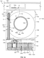
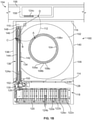
- FIGS. 1A and 1B an example automated diagnostic analyzer 100 is shown in FIGS. 1A and 1B as having a first carousel 102 and a second carousel 104.
- the analyzer 100 may be used, for example, to perform immunoassays, clinical chemistry tests, or any other diagnostics tests.
- the first carousel 102 and the second carousel 104 are rotatably coupled to a base station 106 independent of each other.
- the base station 106 houses different subassemblies and other components used for testing (e.g., performing diagnostic analyses) such as, for example, wash liquid, bulk reagents, a vacuum source, a pressure source, a refrigeration system, temperature sensors, a processor, motors, etc.
- the second carousel 104 is vertically distanced (e.g., spaced) above the first carousel 102 and at least a portion of the second carousel 104 is disposed above and over the first carousel 102.
- the first carousel 102 and the second carousel 104 are disposed next to each other (e.g., coplanar) or may be arranged to be concentric with each other.
- the first carousel 102 is a reagent carousel and the second carousel 104 is a reaction vessel carousel.
- the first and second carousels 102, 104 may hold reagents, samples, reaction vessels or any combination thereof.
- the first carousel 102 includes a plurality of reagent containers (including, for example, liquids having microparticles) arranged annularly around the carousel.
- the first carousel 102 has an inner annular array of reagent containers and outer annular array of reagent containers, concentric with the inner annular array of containers.
- the second carousel 104 is a plate having a plurality of reaction vessels 108a-n disposed around an outer circumference of the plate.
- the reaction vessels 108a-n are reusable cuvettes (e.g., washable glass cuvettes). After a test has been completed in a reaction vessel, the vessel is cleaned (e.g., sterilized) and the vessel may be used for another test.
- the reaction vessels 108a-n are disposable cuvettes (e.g., plastic cuvettes) that are discarded after one or more tests. In operation, the second carousel 104 rotates as one or more assay tests are carried out in the reaction vessels 108a- n .
- a plurality of different modules or instruments may be disposed around the second carousel 104 to, for example, dispense reagents, mix the contents of the reaction vessels, incubate the contents of the reaction vessels, analyze the contents, wash the reaction vessels, etc.
- the example automated diagnostic analyzers disclosed herein also include one or more pipetting mechanisms (e.g., probe arms, automated pipettes, pipettes, etc.) to aspirate and dispense liquids within the reaction vessels 108a-n on the second carousel 104.
- the analyzer 100 includes a pipetting mechanism 110 (e.g., a sample pipette) that is coupled (e.g., mounted) to the base station 106.
- the pipetting mechanism 110 has multiple degrees of freedom.
- the pipetting mechanism 110 has a path of travel 112 (e.g., an arc path, a horizontal arc path, a radius of travel, an operating range), such that the pipetting mechanism 110 can aspirate (e.g., draw liquid) from or dispense liquid to containers located along the path of travel 112.
- the pipetting mechanism 110 is positioned to have access to one of the reaction vessels 108a-n on the second carousel 104 at point A.
- the pipetting mechanism 110 has an axis of rotation and rotates a probe arm with a pipette disposed at the distal end of the probe arm.
- the pipetting mechanism 110 is also movable in the Z direction (e.g., the vertical direction).
- the pipetting mechanism 110 is disposed outside of the first carousel 102 and outside of the second carousel 104, for example, coupled to the base 106 in a position at a distance from the center of the first carousel 102 and the center of the second carousel 104 that is greater than either a first diameter of the first carousel 102 or a second diameter of the second carousel 104.
- the pipetting mechanism 110 is disposed above and over the first carousel 102 and/or adjacent the second carousel 104.
- the pipetting mechanism 110 may be mounted to a platform that is disposed between the first carousel 102 and the second carousel 104.
- the pipetting mechanism 110 may be disposed over the first carousel 102 and over the second carousel 104.
- the example analyzer 100 has a first side 114 (e.g., a front side) and a second side 116 (e.g., a back side, a rear side) opposite the first side 114.
- the pipetting mechanism 110 is disposed near (e.g., adjacent, along, next to, closer to, bordering) the second side 116 of the analyzer 100.
- the analyzer 100 also includes a random sample handler (RSH) 118 (e.g., a loading bay) on the first side 114 of the analyzer 100 for accepting and retaining carriers having samples and/or reagents that are to be used for diagnostic testing.
- RSH random sample handler
- the RSH 118 includes a loading rack 120 having a plurality of slots 122a-n for receiving containers, carriers and/or trays of carriers.
- a plurality of carriers 124a-n have been inserted into the slots 122a-n in the loading rack 120.
- the carriers 124a-n may hold one or more containers (e.g., a tube, a vessel, an open top container, a vial, a cup, etc.).
- the containers may include samples, reagents, calibrations, control liquids, etc., used by the analyzer 100 for assay diagnostic testing.
- an operator e.g., a laboratory technician loads the carriers 124a-n individually or in trays into the loading rack 120 of the RSH 118.
- an automated track system transports the carriers 124a-n to the RSH 118 and loads the carriers 124a-n into respective ones of the slots 122a-n, for example, via a robotic mechanism.
- each of the carriers 124a-n is holding six containers.
- the carriers 124a-n can be configured to hold more or fewer containers depending on the analyzer, the RSH design parameters and/or the carrier layout.
- the carriers 124a-n are held in the slots 122a-n until selected for testing or retesting.
- the RSH 118 includes a positioner 126, which may be a robotic device, to transport the carriers 124a-n and containers coupled thereto to and from the loading rack 120.
- the positioner 126 is movable along a positioner track 128 disposed along the length of the loading rack 120 and the first side 114 of the analyzer 100.
- the positioner 126 has an arm 130 to engage the carriers 124a-n loaded in the RSH 118.
- the positioner 126 and the arm 130 operate to remove the carriers 124a-n from their respective slots 122a-n and transport the carriers 124a-n to different locations along the positioner track 128.
- the example analyzer 100 also includes a first carrier shuttle 134 (e.g., a transporter) and a second carrier shuttle 136 that are disposed near (e.g., along, adjacent, next to, bordering) a third side 138 (e.g., the left side of FIGS. 1A and 1B ) of the analyzer 100, opposite a fourth side 140 (e.g., the right side of FIGS. 1A and 1B ) of the analyzer 100.
- the first side 114, the second side 116, the third side 138 and the fourth side 140 define the outer boundaries of the analyzer 100.
- the analyzer 100 has a rectangular cross-section or footprint. However, in other examples, the analyzer 100 has a square cross-section, a circular cross-section, or any other shaped cross-section or footprint.
- the positioner 126 transports the carriers 124a-n to and from the first carrier shuttle 134 and/or the second carrier shuttle 136.
- the positioner 126 engages the first carrier 124a in the loading rack 120 of RSH 118.
- the positioner 126 transports the first carrier 124a to, in this example, the first shuttle 134, as shown in FIG. 1B , where the positioner 126 releases or otherwise transfers the first carrier 124a onto the first carrier shuttle 134.
- the positioner 126 is controlled by a programmable computer for moving the carriers 124a-n as needed and/or desired (e.g., according to scheduling protocols or timetables) for testing.
- the RSH 118 provides random access to the carriers 124a-n on the loading rack 120.
- the analyzer 100 includes software that allows users to flexibly configure rules or criteria for testing samples.
- the software may be programmed into and/or operated from an example processor 316 ( FIG. 3 ), which is disclosed in more detail below.
- the positioner 126 includes a label reader such as, for example, a barcode reader, a radio frequency identification (RFID) reader and/or other type of reader, to read carrier and container information.
- the label reader reads the labels attached to the carriers, the sample tubes and/or reagent tubes as the positioner 126 passes the carriers by the reader.
- RFID radio frequency identification
- An example RSH and an example positioner are disclosed in U.S. Patent Application Serial No. 12/106,755, titled “ASSAY TESTING DIAGNOSTIC ANALYZER,” filed on April 21, 2008 , which is incorporated herein by reference in its entirety.
- the first and second carrier shuttles 134, 136 operate to move carriers (e.g., the carriers 124a-n) and/or containers between a first position near the first side 114 of the analyzer 100 (e.g., adjacent the rack 120 or the RSH 118) and a second position near the second side 116 of the analyzer 100 (e.g., near the pipetting mechanism 110).
- the first and second carrier shuttles 134, 136 operate to transport carriers 124a-n to a position within the path of travel 112 of the pipetting mechanism 110, such that liquid (e.g., a sample, a specimen) within the containers on the carriers 124a-n can be aspirated from the containers via the pipetting mechanism 110.
- the pipetting mechanism 110 may then dispense the liquid at point A into one or more of the reaction vessels 108a-n on the second carousel 104 for testing.
- the first carrier shuttle 134 includes a first track 142 and the second carrier shuttle 136 includes a second track 144.
- the first track 142 and the second track 144 are conveyor belts that move to transport carriers placed on the respective tracks 142, 144 from one position to another position along the first and second tracks 142, 144.
- the first and second tracks 142, 144 include other track devices such as, for example, a belt, a chain, a carriage, a lead screw, an air cylinder, and/or a linear motor or combinations thereof.
- the first carrier shuttle 134 and the second carrier shuttle 136 comprise different types of tracks.
- the first carrier shuttle 134 includes a first motor 146 (e.g., an electric motor, a servo motor, a stepper motor, etc.) to drive the first track 142 and the second carrier shuttle 136 includes a second motor 148 to drive the second track 144.
- the first and second tracks 142, 144 are operated independently of each other. In other examples, the operations of the first and second tracks 142, 144 are coordinated.
- the first and second motors 146, 148 may be used to rotate one or more pulleys or gears, which, in turn, move the tracks 142, 144.
- the first and second motors 146, 148 are rotatable in either direction to move the first and second tracks 142, 144, respectively, in either direction.
- the first and second motors 146, 148 are located closer to the second side 116 of the analyzer 100.
- the first and second carrier shuttles 134, 136 also include respective sensors 150, 152 such as, for example, a linear encoder and/or a transducer.
- the first and second sensors 150, 152 are located adjacent the first and second tracks 142, 144 to sense a position/movement of the respective tracks 142, 144.
- the first and second sensors 150, 152 provide feedback to the first and second motors 146, 148 to indicate whether the first and second tracks 142, 144 are actually moving when the first and second motors 146, 148 are operating.
- the first and second sensors 150, 152 are positioned on the first and second carrier shuttles 134, 136 opposite the first and second motors 146, 148 as a safety feature to ensure that the tracks 142, 144 are moving when the motors 146, 148 are operating.
- the first and/or second tracks 142, 144 may become dislodged, misaligned or otherwise inoperative and, thus, will not properly transport the carriers.
- the first and second motors 146, 148 may continue to operate (e.g., spin, rotate, etc.) according to a programmed testing protocol.
- the sensors 150, 152 were located adjacent the first and second motors 146, 148, the continued operation of the motors 146, 148 could interfere with the readings of the sensors 146, 148, and cause the sensors 150, 152 to erroneously indicate that the tracks 142, 144 were operating normally.
- the sensors 150, 152 can ensure the tracks 134, 136 are actually moving in accordance with the programming of the first and second motors 146, 148.
- the motors 146, 148 are disposed at, near or closer to the second side 116 of the analyzer 100, and the sensors 150, 152 are at, near or closer to the first side 114 of the analyzer 100. In other examples, this configuration may be switched, such that the motors 146, 148 are disposed at, near or closer to the first side 114 of the analyzer 100, and the sensors 150, 152 are disposed at, near or closer to the second side 116 of the analyzer 100.
- a first carrier 124a can be retrieved from the RSH 118 by the positioner 126 ( FIG. 1A ) and deposited on the first track 142 of the first carrier shuttle 134 ( FIG. 1B ).
- the arm 130 of the positioner 126 includes a hook to engage a tab on the end of the carrier.
- the arm 130 has a gripping mechanism to grip the sides of the carrier.
- the arm 130 is used to grab the first carrier 124a from its respective slot 122a-n in the loading rack 120 ( FIG. 1A ) and then lifts to extract the first carrier 124a from of its respective slot 122a- n .
- the positioner 126 retrieves the first carrier 124a
- the positioner 126 moves (e.g., slides, translates) along the positioner track 128 towards the third side 138 of the analyzer 100 and, thus, towards the first and second carrier shuttles 134, 136.
- the arm 130 of the positioner 126 then rotates to align the first carrier on the first track 142 of the first carrier shuttle 134, as shown in the position in FIG. 1B .
- the arm 130 is capable of rotating at least about 180°.
- the first motor 146 operates to move the first carrier 124a, via the first track 142, from a first position near the first side 114 of the analyzer 100 to a second position near the second side 116 of the analyzer 100 and, thus, within the path of travel 112 of the pipetting mechanism 110.
- the pipetting mechanism 110 may aspirate from a container on the first track 142 along the first path of travel 112 at point B.
- the first motor 146 operates to position the first carrier 124a so that the first path of travel 112 intersects the appropriate container on the first carrier. After aspirating from a container, the pipetting mechanism 110 moves along its first path of travel 112 to dispense the liquid into one or more of the reaction vessels 108a-n on the second carousel 104 at point A.
- the positioner 126 can retrieve a second carrier 124b-n from the RSH 118 and load the second carrier 124b-n onto the second track 144 of the second carrier shuttle 136.
- the second motor 148 operates to move the second carrier 124b-n on the second track 144 from the first position near the first side 114 of the analyzer 100 to the second side 116 of the analyzer 100 near the pipetting mechanism 110.
- the second motor 148 operates to position the second carrier 124b-n along the first path of travel 112 of the pipetting mechanism 110 (e.g., the position shown in FIGS. 1A and 1B ).
- the pipetting mechanism 100 may aspirate from a container on the carrier 124b- n on the second track 144 at point C.
- the first carrier shuttle 134 may simultaneously and independently transport the first carrier 124a to/from the first position adjacent the first side 114 of the analyzer 100 and/or the second position adjacent the second side 116.
- the positioner 126 When a carrier, e.g., the first carrier 124a, returns to the first position adjacent the first side 114 of the analyzer 100, the positioner 126 unloads the first carrier 124a and places the first carrier 124a within one of the slots 122a-n in the loading rack 120. The positioner 126 is then able to retrieve the first carrier 124a or another carrier 124b-n from the loading rack 120 and deposit that carrier 124a-n on the first track 144 of the first carrier shuttle 134.
- a carrier e.g., the first carrier 124a
- one of the carrier shuttles 134, 136 can operate to hold a carrier near the second position for aspiration while another carrier can be loaded onto the other carrier shuttle 134, 136 for subsequent transportation to the second side 116 of the analyzer 100.
- the time between aspirations is reduced, which increases throughput of the example analyzer 100.
- first and second carrier shuttles 134, 136 are aligned substantially parallel to one another and are disposed along the third side 138 of the analyzer 100. However, in other examples, the first and second carrier shuttles 136, 136 may be positioned other locations and/or not parallel to one another. In the example shown, the first and second carrier shuttles 134, 136 are disposed over a portion of the first carousel 102. In other examples, the first and/or second carrier shuttles 134, 136 are disposed outside of the first carousel 102 (i.e., next to the first carousel 102).
- test orders are programmed by an operator or downloaded via a lab information system or any network.
- a test order may require a plurality of assays.
- a programmable computer determines the order (e.g., scheduling, protocols) of the different sample tests based on factors including, for example, number of tests to be conducted, types of reagents to be used, number of reagents to be used, an incubation period, scheduled priority and other factors.
- the positioner 126, the first track 142, the second track 144, the first motor 146, the second motor 148 and other components are controlled in response to commands from the programmable computer.
- a laboratory automated system (LAS) 154 has a main track 156 and a first subtrack or spur 158, which is disposed along the second side 116 of the analyzer 100.
- the LAS 154 may include multiple instruments and equipment for processing and preprocessing certain samples, reagents, calibrations, controls, etc.
- the LAS 154 includes and/or is coupled to a refrigerated storage area, a centrifuge, an aliquoter and/or any other processing station(s).
- the LAS includes a system of tracks and robotic positioners to move carriers from one instrument to another.
- the LAS 154 transports carriers (e.g., sample carriers) or containers to a position near the analyzer 100 and, more specifically, to a position within the first path of travel 112 of the pipetting mechanism 110.
- carriers e.g., sample carriers
- a carrier 124c is depicted on the first subtrack or spur 158.
- the carrier 124c is transported along the main track 156 of the LAS 154 and when the carrier 124c arrives at the first spur 158, the carrier 124c may continue down the main track 156 or may be diverted to the first spur 158 to be sent to the position adjacent the pipetting mechanism 110.
- the path of travel 112 of the pipetting mechanism 110 extends beyond the second side 116 of the analyzer 110.
- the pipetting mechanism 110 may aspirate a liquid (e.g., a sample) from a container on the carrier at the first spur 158 at point D.
- a liquid e.g., a sample
- the main track 156 and the spur 158 of the LAS 154 are substantially parallel to the second side 116 of the analyzer 100 and are substantially perpendicular to the first and second carrier shuttles 134, 136.
- the pipetting mechanism 110 is located near the second side 116 of the analyzer 100 and has access (e.g., can aspirate from and/or can dispense to) to the reaction vessels 108a-n on the second carousel 104 at point A, a carrier on the first track 142 of the first carrier shuttle 134 at point B, a carrier the second track 144 of the second carrier shuttle 136 at point C and/or a carrier on the spur 158 of the LAS 154 at point D.
- access e.g., can aspirate from and/or can dispense to
- the pipetting mechanism 110 has access to carriers loaded in the RSH 118 at the first side 114 (e.g., the front side) of the analyzer 110 (via one or more of the carrier shuttles 134, 136) and carriers transported along the track 156 of the LAS 154 on the second side 116 (e.g., the back side) of the analyzer 100. Continuous access to carriers at different locations around the pipetting mechanism 110 points allows the pipetting mechanism 110 to aspirate from multiple sample containers more efficiently and with less idle or down time and, as a result, increases the throughput of the example analyzer 100.
- FIG. 2 illustrates an example laboratory system 200 having a first diagnostic analyzer 202 (e.g., a first module), a second diagnostic analyzer 204 (e.g., a second module) and a laboratory automation system (LAS) 206.
- the first analyzer 202 includes a first carousel 208 and a second carousel 210.
- the second carousel 210 is reaction carousel having a plurality of reaction vessels for conducting diagnostic tests on one or more samples in the plurality of reaction vessels.
- the first analyzer 202 also includes a first random sample handler (RSH) 212 (e.g., a first loading bay) disposed along a first side 214 (e.g., a front side) of the first analyzer 202, opposite a second side 216 (e.g., a rear side) of the first analyzer 202.
- RSH random sample handler
- a first pipetting mechanism 218 is disposed on the first analyzer 202 adjacent the second side 216 of the first analyzer 202 and has a first path of travel 220 (e.g., horizontal arc path, range of access).
- the first analyzer 202 further includes a first carrier shuttle 222 and a second carrier shuttle 224 located along a third side 226 (e.g., the left side) of the first analyzer 202, opposite a fourth side 228 (e.g., the right side) of the first analyzer 202.
- each of the first and second carrier shuttles 222, 224 has a respective track 230, 232 (e.g., lead screw) and a respective carriage 234, 236 (e.g., shuttles).
- the first and second tracks 230, 232 operate to move the respective carriages 234, 236 from a first position near the first side 214 of the first analyzer 202 to a second position near the second side 216 of the first analyzer 202 and within the first path of travel 220 of the first pipetting mechanism 218.
- the first and second carriages 234, 236 are platforms for holding a carrier. As the first and second tracks 230, 232 operate (e.g., rotate), the first and second carriages 234, 236 move along the longitudinal axes of the respective track 230, 232.
- the second analyzer 204 includes similar components as the first analyzer 202 such as, for example, a third carousel 238 (e.g., a reagent carousel), a fourth carousel 240 (e.g., a reaction carousel), a second RSH 242, a first side 244 (e.g., a front side) opposite a second side 246 (e.g., a rear side), a third side 248 (e.g., a left side) opposite a fourth side 250 (e.g., a right side), a second pipetting mechanism 252 with a second path of travel 254, a third carrier shuttle 256, a fourth carrier shuttle 258, a third track 260 (e.g., a third lead screw), a fourth track 262 (e.g., a fourth lead screw), a third carriage 264 and a fourth carriage 266.
- a third carousel 238 e.g., a reagent carousel
- the third and fourth carrier shuttles 256, 258 of the second analyzer 204 operate to transport carriers from a first position adjacent the first side 244 of the second analyzer 204 to a second position adjacent the second side 246 of the second analyzer 204 and within the second path of travel 254 of the second analyzer 204.
- a positioner 268 is movable along a positioner path 270 between the first and second RSH 212, 242 and along the first sides 214, 244 of the first and second analyzers 202, 204.
- only one positioner 268 is utilized to transport carriers among the first RSH 212, the second RSH 242, the first track 230, the second track 232, the third track 260 and/or the fourth track 262.
- the positioner 268 is substantially similar to the positioner 126 disclosed above in connection with FIGS. 1A and 1B .
- the positioner 268 may retrieve carriers loaded within the first and second RSH 212, 242 and may transport the carriers via the first, second, third or fourth carrier shuttles 222, 224, 256, 258.
- a first plurality of carriers 272a -n are loaded in the first RSH 212
- a second plurality of carriers 274a-n are loaded in the second RSH 242.
- the positioner 268 is to retrieve one of the first or second plurality of carriers 272a -n, 274a-n and is to place (e.g., position, deposit, transport) the carrier on one of the first, second, third or fourth carrier shuttles 222, 224, 256, 258.
- the carriers 272a-n, 274a-n may then be transported via one of the carriages 234, 236, 264, 266 and tracks 230, 232, 260, 262 to a position near the second side 216, 246 of one of the analyzers 202, 204.
- the first pipetting mechanism 218 of the first analyzer 202 may aspirate from a container in a first carrier on the first carriage 234 at point A and may aspirate from another container in a second carrier on the second carriage 236 at point B, which are both along the first path of travel 220.
- the second pipetting mechanism 252 may aspirate from a container in a third carrier on the third carriage 264 at point C and may aspirate from another container in a fourth carrier on the fourth carriage 266 at point D, both of which are along the second path of travel 254 of the second pipetting mechanism 252.
- the first pipetting mechanism 218 may access one or more reaction vessels on the second carousel 210 at point E
- the second pipetting mechanism 252 may access one or more reaction vessels on the fourth carousel 240 at point F.
- the LAS 206 includes a main track 276 that is disposed along the second sides 216, 246 of the first and second analyzers 202, 204.
- the main track 276 has a first subtrack or spur 278 and a second subtrack or spur 280.
- the first spur 278 displaces a carrier on the main track 276 to a position near the second side 216 of the first analyzer 202 and within the first path of travel 220 of the first pipetting mechanism 218.
- the second spur 280 displaces a carrier on the main track 276 to a position near the second side 246 of the second analyzer 204 and within the second path of travel 254 of the second pipetting mechanism 252.
- the first pipetting mechanism may aspirate from a container on a carrier on the first spur 278 at point G
- the second pipetting mechanism 252 may aspirate from another container on another carrier on the second spur 280 at point H.
- the track 276 of the LAS 206 may be configured to traverse along or near the analyzers to supply the analyzers with access to additional carriers.
- the LAS 206 transports carriers having additional liquids such as, for example, priority samples for testing, calibration and control liquids, additional reagents (including, for example, liquids with microparticles), etc.
- the LAS 206 is tied to additional equipment such as, for example, a refrigerated storage area 282, a centrifuge 284 and/or an aliquoter 286.
- a body liquid may be analyzed, such as, for example, serum or plasma.
- Serum is the yellow, watery part of blood that is left after blood has been allowed to clot and all blood cells have been removed such as, for example, via centrifugation, which packs the denser blood cells and platelets to the bottom of a centrifuge tube and leaves the liquid serum fraction resting above the packed cells.
- Plasma is similar to serum but is obtained by centrifuging blood without clotting.
- the LAS 206 of example system 200 enables sample liquids such as, for example, serum or plasma to be processed in the centrifuge 284 and then transported to one or more of the first and second analyzers 202, 204 for diagnostic testing.
- the LAS 206 allows priority samples to be loaded onto carriers and sent along the track 276 to a position within the first and/or second paths of travel 220, 254 of the respective pipetting mechanisms 218, 252.
- the pipetting mechanisms 218, 252 near the second sides 216, 246 of the analyzers 202, 204, and by providing the carrier shuttles 222, 224, 256, 258 to transport carrier to and from the first and second sides 214, 244, 216, 246 of the analyzers 202, 204, the analyzers 202, 204 may receive samples in a traditional operating manner through the first sides 214, 244 and/or may receive samples from the LAS 206 at the second sides 216, 246.
- the analyzers 202, 204 can be arranged in a side-by-side configuration without interfering with operations of the respective analyzers 202, 204 and, thus, laboratory floor space is decreased.
- FIG. 3 is a block diagram of an example processing system 300 for use with any of the analyzers 100, 202, 204 and/or the LAS 154, 206 disclosed herein.
- Example analyzers disclosed herein are used to, for example, perform diagnostic testing on multiple test samples using one or more reagents and/or other diagnostic test procedures.
- the example processing system 300 includes a carousel controller 302 to control the operations (e.g., rotational sequences, locksteps, indexing, etc.) of one or more carousels on an analyzer.
- an analyzer includes one or more carousels having a plurality of containers or vessels.
- the analyzer includes a first carousel having a plurality of reagent containers that contain reagents for diagnostic testing and a second carousel having a plurality of vessels (e.g., reaction vessels) that are used for testing the samples.
- the analyzer 100 disclosed above includes the first carousel 102 (e.g., a reagent carousel), and the second carousel 104 (e.g., a reaction carousel).
- the second carousel 104 includes a plurality of reaction vessels 108a-n and rotates the reaction vessels 108a-n in a continuous or discrete manner while a plurality of diagnostic functions are performed on the reaction vessels 108-n.
- the carousel controller 302 may be used, for example, to control the rotational sequence (e.g., lockstep timing) of the first and second carousels 102, 104.
- the example processing system 300 includes a pipette controller 304.
- an analyzer utilizes one or more pipettes (e.g., automated pipetting mechanisms, probe arms, etc.) to aspirate a fluid from one location and dispense the fluid into another location.
- an analyzer has multiple pipettes such as, for example, a first pipette for dispensing a sample into a reaction vessel, a second pipette for dispensing a first reagent into a reaction vessel, a third pipette for dispensing a second reagent into a reaction vessel, etc.
- the pipette controller 306 operates to control the pipettes such as, for example, the movement of the pipettes, the vacuum applied to the pipettes for aspirating, the pressure applied to the pipettes for dispensing, etc.
- the analyzer 100 includes the pipetting mechanism 110, which moves a pipette along the path of travel 112 to aspirate and dispense fluid such as, for example, sample.
- the example pipetting mechanism 110 dispenses sample into the reaction vessels 108a-n on the second carousel 104 at point A.
- the pipette controller 304 is used to control the pipetting mechanism 110.
- the example processing system 300 includes a reader controller 306.
- a reader e.g., an analyzer
- the reader may analyze the contents of the respective reaction vessels.
- a reaction vessel is held stationary in front of the reader for a predetermined time and a reading is taken.
- one or more reaction vessels may be passed continuously in front of the reader, and the reader takes a plurality of individual readings corresponding to each reaction vessel.
- the reader controller 306 operates to control when the readings are taken.
- the reader controller 306 may also be used to control other readers.
- a reader positioned near the RSH 118 may be operated to read an RFID tag, a bar code, a QR code or other machine readable code to gather information about the identity of or other data related to the contents of a carrier 124a-n and/or a container coupled to the carrier 124a-n.
- the example processing system 300 also includes a positioner controller 308 and a shuttle controller 310.
- an analyzer includes a loading bay for receiving containers, carriers having containers and/or trays of carriers.
- the containers may include reagents, samples, controls, calibrations, etc.
- the loading bay is disposed on a first side or front side of the analyzer.
- a positioner e.g., a robotic mechanism retrieves the carriers from the loading bay and transports the carriers to different areas of the analyzer for testing and retesting.
- the positioner controller 308 controls the movement of the positioner to engage and move carriers in the analyzer.
- the positioner 126 translates along the track 128 on the first side 114 of the analyzer 100.
- the positioner 126 also has the arm 130 that rotates to engage carriers in the RSH 118.
- the positioner controller 308 may be used, for example, to control the movement of the positioner 126 and the arm 130 along the track 128.
- an analyzer includes one or more shuttle carriers to transport carriers from one side of the analyzer to the other side of the analyzer.
- the pipette is disposed along a second side or rear side of the analyzer and the carrier shuttle(s) transports the carriers from the front of the analyzer adjacent the loading bay to a position near the back side of the analyzer and within the range of the pipette.
- the carrier shuttles are operated by motors (e.g., electric motors, servo motors, stepper motors, etc.).
- the shuttle carriers utilize a track system such as, for example, a conveyor belt or a lead screw, to transport the carriers.
- the carrier shuttle controller 310 operates to control the movement of the one or more carrier shuttles to transport carriers along the carrier shuttle(s).
- the carrier shuttle controller 310 may be used, for example, to control the motors 146, 148 of the respective carrier shuttles 134, 136.
- the example processing system 300 includes sensors 312 communicatively coupled to the shuttle carrier controller 310.
- one or more sensors e.g., transducers, encoders, etc.
- the sensors 312 are disposed at an opposite end of the carrier shuttles than the motors.
- the sensors 150, 152 are disposed along the tracks 142, 146 of the respective carrier shuttles 134, 136 to determine whether the tracks 142, 146 of the respective shuttle carriers 134, 136 are operating effectively and that the tracks 142, 146 are not dislodged, misaligned or otherwise inoperable.
- the example processing system 300 includes a laboratory automation system (LAS) controller 314.
- a laboratory automation system includes a system of tracks and instruments to transport carriers around a laboratory. Some samples, reagents, and other liquids used in diagnostic testing, require additional processing steps and/or refrigeration.
- the LAS may connect to various instruments and, when time for processing, the LAS may transport the liquid (e.g., a priority sample), via a carrier, to the back side of the analyzer for aspirating by the pipette.
- the main track of the LAS includes a subtrack or spur to transport a carrier to the rear side of the analyzer, such that the carrier is not held stationary on the main track.
- the LAS controller 314 controls operation of the LAS including, for example, the main track, the spurs, and/or any equipment or instruments attached thereto.
- the example LAS 154 disclosed above includes the main track 156 and the spur 158 to transport a carrier (e.g., 124c) to a location adjacent the rear side of the analyzer 100, such that the pipetting mechanism 110 may aspirate from the contents of the carrier.
- a carrier e.g., 124c
- the example processing system 300 also includes a processor 316 and a database 318.
- the processor interfaces with the controllers and sensors 302-314 of the processing system 300 to control the various operations of each of the components.
- the processor 316 is programmable to operate in accordance with desired testing protocol(s).
- the database 318 may be used to store, for example, information regarding tests that have occurred, are to occur, and/or are occurring, testing protocol(s), information regarding the individual samples and/or reagents data gathered from the reader(s), position(s) of the carrier(s), postioner(s), carrier shuttle(s), pipetting mechanism(s), LAS, and/or carousel(s), and/or other information.
- the processing system components 302-318 are communicatively coupled to other components of the example system 300 via communication links 320.
- the communication links 320 may be any type of wired connection (e.g., a databus, a USB connection, etc.) or a wireless communication mechanism (e.g., radio frequency, infrared, etc.) using any past, present or future communication protocol (e.g., Bluetooth, USB 2.0, USB 3.0, etc.).
- the components of the example system 300 may be integrated in one device or distributed over two or more devices.
- FIG. 3 While an example manner of implementing the analyzers 100, 202, 204 and/or the LAS 154, 206 of FIGS. 1A-2 is illustrated in FIG. 3 , one or more of the elements, processes and/or devices illustrated in FIG. 3 may be combined, divided, re-arranged, omitted, eliminated and/or implemented in any other way. Further, the example carousel controller 302, the example pipette controller 304, the example reader controller 306, the example positioner controller 308, the example carrier shuttle controller 310, the example sensor(s) 312, the example LAS controller 314, the example processor 316, the example database 318 and/or, more generally, the example processing system 300 of FIG.
- any of the example carousel controller 302, the example pipette controller 304, the example reader controller 306, the example positioner controller 308, the example carrier shuttle controller 310, the example sensor(s) 312, the example LAS controller 314, the example processor 316, the example database 318 and/or, more generally, the example processing system 300 could be implemented by one or more analog or digital circuit(s), logic circuits, programmable processor(s), application specific integrated circuit(s) (ASIC(s)), programmable logic device(s) (PLD(s)) and/or field programmable logic device(s) (FPLD(s)).
- ASIC application specific integrated circuit
- PLD programmable logic device
- FPLD field programmable logic device
- At least one of the example carousel controller 302, the example pipette controller 304, the example reader controller 306, the example positioner controller 308, the example carrier shuttle controller 310, the example sensor(s) 312, the example LAS controller 314, the example processor 316 and/or the example database 318 is/are hereby expressly defined to include a tangible computer readable storage device or storage disk such as a memory, a digital versatile disk (DVD), a compact disk (CD), a Blu-ray disk, etc. storing the software and/or firmware.
- the example processing system 300 of FIG. 3 may include one or more elements, processes and/or devices in addition to, or instead of, those illustrated in FIG. 3 , and/or may include more than one of any or all of the illustrated elements, processes and devices.
- FIG. 4 A flowchart representative of an example method 400, at least some of which are machine readable, for implementing the example analyzers 100, 202, 204, the example LAS 154, 206 and/or the example processing system 300 is shown in FIG. 4 .
- the method 400 may be implemented using machine readable instructions that comprise a program for execution by a processor such as the processor 512 shown in the example processor platform 500 discussed below in connection with FIG. 5 .
- the program may be embodied in software stored on a tangible computer readable storage medium such as a CD-ROM, a floppy disk, a hard drive, a digital versatile disk (DVD), a Blu-ray disk, or a memory associated with the processor 512, but the entire program and/or parts thereof could alternatively be executed by a device other than the processor 512 and/or embodied in firmware or dedicated hardware.
- a tangible computer readable storage medium such as a CD-ROM, a floppy disk, a hard drive, a digital versatile disk (DVD), a Blu-ray disk, or a memory associated with the processor 512, but the entire program and/or parts thereof could alternatively be executed by a device other than the processor 512 and/or embodied in firmware or dedicated hardware.
- a device such as a CD-ROM, a floppy disk, a hard drive, a digital versatile disk (DVD), a Blu-ray disk, or a memory associated with the processor 512
- DVD digital versatile disk
- coded instructions e.g., computer and/or machine readable instructions
- a tangible computer readable storage medium such as a hard disk drive, a flash memory, a read-only memory (ROM), a compact disk (CD), a digital versatile disk (DVD), a cache, a random-access memory (RAM) and/or any other storage device or storage disk in which information is stored for any duration (e.g., for extended time periods, permanently, for brief instances, for temporarily buffering, and/or for caching of the information).
- a tangible computer readable storage medium is expressly defined to include any type of computer readable storage device and/or storage disk and to exclude propagating signals.
- tangible computer readable storage medium and “tangible machine readable storage medium” are used interchangeably. Additionally or alternatively, the example processes of FIG. 4 may be implemented using coded instructions (e.g., computer and/or machine readable instructions) stored on a non-transitory computer and/or machine readable medium such as a hard disk drive, a flash memory, a read-only memory, a compact disk, a digital versatile disk, a cache, a random-access memory and/or any other storage device or storage disk in which information is stored for any duration (e.g., for extended time periods, permanently, for brief instances, for temporarily buffering, and/or for caching of the information).
- coded instructions e.g., computer and/or machine readable instructions
- a non-transitory computer and/or machine readable medium such as a hard disk drive, a flash memory, a read-only memory, a compact disk, a digital versatile disk, a cache, a random-access memory and/or any other storage device or storage disk in which information is
- non-transitory computer readable medium is expressly defined to include any type of computer readable device or disk and to exclude propagating signals.
- phrase “at least” is used as the transition term in a preamble of a claim, it is open-ended in the same manner as the term “comprising” is open ended.
- FIG. 4 is a flowchart representing the example diagnostic testing method 400 that may be implemented, for example, by the analyzers 100, 202, 204, the LAS 154, 206 and/or the processing system 300 detailed above.
- the example analyzers include a first carousel and a second carousel, the second carousel being a reaction carousel having a plurality of reaction vessels for conducting diagnostic tests. As the reaction carousel rotates, a plurality of automated modules each perform assay steps on the individual reaction vessels.
- the example analyzers have a first side (e.g., a front side) and a second side (e.g., a back side), opposite the first side.
- a pipetting mechanism is disposed near the second side of the analyzer to dispense sample into the reaction vessels on the reaction carousel as the reaction carousel rotates.
- a loading bay is disposed on the first side of the example analyzer to receive carriers or trays of carriers.
- the example method or process 400 includes loading carriers in the first side of the analyzer (block 402).
- each carrier includes multiple containers such as, for example, test tubes having test samples.
- the example process 400 also includes transporting a first carrier to a first carrier shuttle (block 404).
- the example analyzer 100 disclosed above includes a first carrier shuttle 134 and a second carrier shuttle 136 to transport carriers from the first side 114 of the analyzer 100 to the second side 116 of the analyzer 100.
- a positioner is located along the loading bay to retrieve carriers from respective slots and transfer the carriers to other locations in the analyzer including, for example, to a carrier shuttle.
- the example process 400 includes transporting the first carrier from the first side of the analyzer to the second side of the analyzer (block 406).
- the first carrier shuttle includes a conveyor belt and a motor to transport the first carrier.
- the first carrier shuttle comprises a lead screw and a carriage, such that the first carrier may be placed in the carriage and the first lead screw operates (e.g., rotates) to move the carriage (and the first carrier) from the first side of the analyzer to the second side of the analyzer.
- the first carrier shuttle has a sensor (e.g., an encoder, a transducer) to sense movement of the conveyor belt, as a safety feature.
- the example process 400 also includes aspirating a liquid from the first carrier (block 408).
- the example analyzer 100 disclosed above locates the pipetting mechanism 110 adjacent the second side 116 of the analyzer 100.
- the first carrier shuttle 134 is to transport the first carrier from a first location near the first side 114 of the analyzer 100 to a second location near the second side 116 of the analyzer and, more specifically, within an access range (e.g., the path of travel 112, a horizontal arc path, etc.) of the pipetting mechanism 110, to enable the pipetting mechanism 110 to aspirate from the first carrier.
- the liquid is dispensed into a first reaction vessel (block 410).
- the pipetting mechanism 110 has an axis of rotation and a probe arm with a pipette disposed on the distal end of the probe arm.
- the probe arm rotates to access liquids along a path of travel (e.g., a horizontal arc path) and dispenses the aspirated liquid into the first reaction vessel on the reaction carousel 104.
- the example process includes determining whether there is a second carrier shuttle (412).
- the analyzer employs only one carrier shuttle.
- a second carrier shuttle is utilized to reduce turnaround time and increase throughput.
- the second carrier shuttle is independently operated. Therefore, one or more of the operations of the second carrier shuttle and/or components related thereto (e.g., blocks 314, 316, 318, 320) may occur independently and/or simultaneously relative to the one or more of the operation of the first carrier shuttle and/or components related thereto (e.g., blocks 304, 306, 308, 310).
- the example process 400 includes transporting a second carrier to the second carrier shuttle (block 414).
- the positioner 126 of the analyzer 100 retrieves the second carrier 124b-n from a slot 122b-n in the loading bay 120 and transports the second carrier 124b-n to the second carrier shuttle 136.
- the example process 400 also includes transporting the second carrier from the first side of the analyzer to the second side of the analyzer (block 416).
- the second carrier shuttle includes a conveyor belt or a lead screw. The second carrier shuttle operates to transport the second carrier from the first location near the first side of the analyzer to the second location adjacent the second side of the analyzer and, more specifically, to a location within the path of travel of the pipetting mechanism.
- the example process 400 includes aspirating a liquid from the second carrier (block 418) and dispensing the liquid into a second reaction vessel on the reaction carousel (420).
- the example process 400 includes transporting a third carrier to the second side of the analyzer (block 422).
- the example analyzer 100 may include the laboratory automation system (LAS) 154.
- the LAS 154 has a track system 156 to transport carriers and/or containers of diagnostic testing liquid around a laboratory, and a portion of the track (e.g., 158) is disposed adjacent the second side of the analyzer.
- the transport of the third carrier is independent of the transport of the first and/or second carriers.
- one or more of the operations of the first and second carrier shuttle and/or components related thereto may occur independently and/or simultaneously relative to the one or more of the operation of the LAS 154 and/or components related thereto (e.g., blocks 322, 324, 326).
- the example process 400 also includes aspirating a liquid from the third carrier (block 424).
- the LAS 154 includes the spur 158 that directs the third carrier 124c from the main track 156 to a position within the path of travel 112 of the pipetting mechanism 110 to enable access for aspirating the liquid from the third carrier 124c.
- the example process 300 also includes dispensing the liquid into a third reaction vessel on the reaction carousel (block 426).
- the pipetting mechanism 110 may move in the path of travel 112 and dispense aspirated liquid into a reaction vessel on the second carousel 104.
- the example process includes determining whether additional tests are to be performed (block 428). If further testing is desired, then the example process includes transporting the first carrier, via the first shuttle carrier, from the second location to the first location adjacent the first side of the analyzer (block 430). In some examples, the positioner removes the first carrier from the first carrier shuttle and places the first carrier in an empty slot in the loading bay. The example process may then continue with loading or transporting another carrier (block 404) onto the first carrier shuttle (i.e., as the "first" carrier in the illustrated example process 400), and the example process 400 proceeds as disclosed above. If further testing is not desired and/or needed (bock 428), then the example process 400 ends (block 432).
- FIG. 5 is a block diagram of an example processor platform 500 capable of executing the instructions to be performed of FIG. 4 to implement one or more portions of the apparatus and/or systems of FIGS. 1A-3 .
- the processor platform 500 can be, for example, a server, a personal computer, a mobile device, a personal digital assistant (PDA), an Internet appliance, and/or or any other type of computing device.
- PDA personal digital assistant
- the processor platform 500 of the illustrated example includes a processor 512.
- the processor 512 of the illustrated example is hardware.
- the processor 512 can be implemented by one or more integrated circuits, logic circuits, microprocessors or controllers from any desired family or manufacturer.
- the processor 512 of the illustrated example includes a local memory 513 (e.g., a cache).
- the processor 512 of the illustrated example is in communication with a main memory including a volatile memory 514 and a non-volatile memory 516 via a bus 518.
- the volatile memory 514 may be implemented by Synchronous Dynamic Random Access Memory (SDRAM), Dynamic Random Access Memory (DRAM), RAMBUS Dynamic Random Access Memory (RDRAM) and/or any other type of random access memory device.
- the non-volatile memory 516 may be implemented by flash memory and/or any other desired type of memory device. Access to the main memory 514, 516 is controlled by a memory controller.
- the processor platform 500 of the illustrated example also includes an interface circuit 520.
- the interface circuit 520 may be implemented by any type of interface standard, such as an Ethernet interface, a universal serial bus (USB), and/or a PCI express interface.
- one or more input devices 522 are connected to the interface circuit 520.
- the input device(s) 522 permit(s) a user to enter data and commands into the processor 512.
- the input device(s) can be implemented by, for example, an audio sensor, a microphone, a camera (still or video), a keyboard, a button, a mouse, a touchscreen, a track-pad, a trackball, isopoint and/or a voice recognition system.
- One or more output devices 524 are also connected to the interface circuit 520 of the illustrated example.
- the output devices 524 can be implemented, for example, by display devices (e.g., a light emitting diode (LED), an organic light emitting diode (OLED), a liquid crystal display, a cathode ray tube display (CRT), a touchscreen, a tactile output device and/or a light emitting diode (LED).
- the interface circuit 520 of the illustrated example thus, typically includes a graphics driver card, a graphics driver chip or a graphics driver processor.
- the interface circuit 520 of the illustrated example also includes a communication device such as a transmitter, a receiver, a transceiver, a modem and/or network interface card to facilitate exchange of data with external machines (e.g., computing devices of any kind) via a network 526 (e.g., an Ethernet connection, a digital subscriber line (DSL), a telephone line, coaxial cable, a cellular telephone system, etc.).
- a communication device such as a transmitter, a receiver, a transceiver, a modem and/or network interface card to facilitate exchange of data with external machines (e.g., computing devices of any kind) via a network 526 (e.g., an Ethernet connection, a digital subscriber line (DSL), a telephone line, coaxial cable, a cellular telephone system, etc.).
- DSL digital subscriber line
- the processor platform 500 of the illustrated example also includes one or more mass storage devices 528 for storing software and/or data.
- mass storage devices 528 include floppy disk drives, hard drive disks, compact disk drives, Blu-ray disk drives, RAID systems, and digital versatile disk (DVD) drives.
- Coded instructions 532 to implement the method of FIG. 4 may be stored in the mass storage device 528, in the volatile memory 514, in the non-volatile memory 516, and/or on a removable tangible computer readable storage medium such as a CD or DVD.
- the present invention is further defined by the following items:
Landscapes
- Health & Medical Sciences (AREA)
- Chemical & Material Sciences (AREA)
- Life Sciences & Earth Sciences (AREA)
- Immunology (AREA)
- Pathology (AREA)
- Analytical Chemistry (AREA)
- Biochemistry (AREA)
- General Health & Medical Sciences (AREA)
- General Physics & Mathematics (AREA)
- Physics & Mathematics (AREA)
- Engineering & Computer Science (AREA)
- Chemical Kinetics & Catalysis (AREA)
- Biomedical Technology (AREA)
- Hematology (AREA)
- Molecular Biology (AREA)
- Urology & Nephrology (AREA)
- Biotechnology (AREA)
- Cell Biology (AREA)
- Microbiology (AREA)
- Food Science & Technology (AREA)
- Medicinal Chemistry (AREA)
- Robotics (AREA)
- Automatic Analysis And Handling Materials Therefor (AREA)
Abstract
Description
- The present disclosure relates generally to automated diagnostic analyzers and, more particularly, to automated diagnostic analyzers having rear accessible track systems and related methods.
- Healthcare diagnostics laboratories use diagnostic instruments for testing and analyzing specimens or samples. Known automated diagnostic analyzers employ multiple carousels and multiple pipetting mechanisms to automatically aspirate liquid from and dispense liquid to different areas in the analyzer to perform diagnostic analysis procedures. The carousels may include a carousel for reaction vessels and a carousel for reagents. By arranging multiple containers on the respective carousels, these known analyzers are capable of conducting multiple assays on multiple test samples as the carousels rotate. These analyzers typically include a pipetting mechanism that aspirates a sample from a sample container and dispenses the sample into one or more reaction vessels on one of the carousels. A robotic device is utilized to individually transport a single sample container at a time to a region near the sample pipetting mechanism for aspiration.
-
-
FIG. 1A is a top view of an example analyzer having an example sample positioner in a first position in accordance with the teachings of this disclosure. -
FIG. 1B shows the example analyzer ofFIG. 1A with the example positioner in a second position. -
FIG. 2 illustrates an example laboratory system in accordance with the teachings of this disclosure. -
FIG. 3 is a block diagram of an example processing system for the example analyzers and laboratory systems shown inFIGS. 1 and2 . -
FIG. 4 is a flowchart illustrating an example diagnostic testing process. -
FIG. 5 is a diagram of a processor platform for use with the examples disclosed herein. - Certain examples are shown in the above-identified figures and described in detail below. In describing these examples, like or identical reference numbers are used to identify the same or similar elements. The figures are not necessarily to scale and certain features and certain views of the figures may be shown exaggerated in scale or in schematic for clarity and/or conciseness. Additionally, several examples have been described throughout this specification. Any features from any example may be included with, a replacement for, or otherwise combined with other features from other examples.
- Diagnostics laboratories employ diagnostic instruments such as those for testing and analyzing specimens or samples including, for example, clinical chemistry analyzers, immunoassay analyzers and hematology analyzers. Specimens and biological samples are analyzed to, for example, check for the presence or absence of an item of interest including, for example, a specific region of DNA, mitochondrial DNA, a specific region of RNA, messenger RNA, transfer RNA, mitochondrial RNA, a fragment, a complement, a peptide, a polypeptide, an enzyme, a prion, a protein, an antibody, an antigen, an allergen, a part of a biological entity such as a cell or a viron, a surface protein, and/or functional equivalent(s) of the above. Specimens such as a patient's body fluids (e.g., serum, whole blood, urine, swabs, plasma, cerebra-spinal fluid, lymph fluids, tissue solids) can be analyzed using a number of different tests to provide information about the patient's health.
- Generally, analysis of a test sample involves the reaction of test samples with one or more reagents with respect to one or more analytes. The reaction mixtures are analyzed by an apparatus for one or more characteristics such as, for example, the presence and/or concentration of a certain analyte in the test sample. Use of automated diagnostic analyzers improves the efficiency of the laboratory procedures as the technician (e.g., an operator) has fewer tasks to perform and, thus, the potential for operator or technician error is reduced. In addition, automated diagnostic analyzers also provide results much more rapidly and with increased accuracy and repeatability.
- Automated diagnostic analyzers use multiple pipettes to move liquids between storage containers (e.g., receptacles such as open topped tubes) and containers in which the specimens are to be processed (e.g., reaction vessels). For example, a specimen may be contained in a tube that is loaded in a rack on an analyzer, and a head carrying a pipette moves the pipette into the tube where a vacuum is applied to extract a selected amount of the specimen from the tube into the pipette. The head retracts the pipette from the tube and moves the pipette to another tube or reaction vessel located at a processing station, depositing the extracted amount of the specimen from the pipette into the reaction vessel. A reagent is similarly acquired from a reagent supply.
- In other examples, a track or positioner (e.g., a robotic device) is disposed at the front of an analyzer to move a sample tube or a sample carrier to a position near a pipette such that the pipette can aspirate from the sample tube. In such examples, a loading bay or rack is disposed on the front side of the analyzer to receive and hold multiple carriers, which may contain, for example, samples and/or reagents to be used in the diagnostic testing. To position samples for testing, the positioner retrieves the carrier from the loading bay and transfers the carrier to a location near an operating range of the sample pipette, which is also adjacent the front of the analyzer. After aspiration, the positioner transports the sample carrier back to the loading bay and reloads the sample carrier in a respective slot. The positioner may then retrieve a second carrier and likewise transfers the second carrier to the location near the sample pipette.
- However, the pipetting mechanisms of these known analyzers are only able to aspirate samples from sample tubes that are positioned in a specific location by the positioner. In addition, because only one positioner is utilized, the positioner can only retrieve and hold one carrier at a time and, thus, there are increased time delays between aspirations from different carriers.
- Additionally, for some diagnostic testing, some samples may have a higher priority for testing, some samples and/or reagents may need to be refrigerated and/or other samples and/or reagents may involve additional processing steps (e.g., centrifugation, incubation) prior to analysis. Some known laboratories use a laboratory automated system having a track to transport priority samples and other liquids (e.g., reagents, calibration fluids, control fluids, wash fluids, etc.) to the analyzers. In some known configurations, the track is located along a side of the analyzer and transports the priority samples to a location within the operating range of the sample pipetting mechanism. This arrangement increases the footprint of the analyzer particularly in configurations in which multiple analyzers (e.g., modules) are arranged next to each other. Also, the track system being disposed on the sides of the analyzers prevents the alignment (e.g., a side-by-side layout) of multiple modules, and in some examples, it may be desired to add multiple modules (e.g., analyzers) to increase throughput of a laboratory or facility utilizing the analyzers. In other known configurations, the track system is disposed along the front of the analyzers outside of the front loading bay. However, with this arrangement, additional robotic mechanisms and/or spurs are needed to move the carriers from the track system to the loading bay, and then from the loading bay into the analyzer. Additionally, with this arrangement, the track system blocks access to the front loading bay and, thus, an operator or technician is not able to manually load samples and/or reagents for diagnostic testing.
- The example analyzers disclosed herein have a sample pipette (e.g., a pipetting mechanism) disposed near a rear side of the analyzer and one or more shuttle carriers to transport sample carriers from a front side of the analyzer to the rear side of the analyzer near the sample pipette. The sample pipette is positioned to aspirate sample liquid from sample tubes in the carriers and to dispense the sample liquid into one or more reaction vessels in the analyzer.
- In some examples, the analyzer includes two carrier shuttles that operate independently of each other, which decreases time between aspirations and, thus, increases throughput of the analyzer. Additionally, by locating the sample pipette adjacent the rear side of the analyzer, a laboratory automated system (LAS) track can be disposed (e.g., mounted) at or along the rear side of analyzer without interfering with the layout of the laboratory. For example, multiple modules or analyzers may be aligned side-by-side, and the LAS track may traverse along the rear side of the modules for delivering additional samples (e.g., priority samples) and sample carriers to the individual analyzers. Therefore, the example analyzers may perform diagnostic testing according to traditional protocols or schedules that utilize the front loading bay and may also receive priority samples and other liquids (e.g., calibration/control liquids) from the LAS without interrupting normal operations of the analyzer. Additionally, the modularity of the example analyzers allows more or less analyzers (e.g., one, two, three, four or more) to be utilized depending on the demand (e.g., increased demand for immunoassay testing and/or clinical chemistry testing) of the laboratory or facility. In examples with multiple analyzers, the analyzers may be any combination of immunoassay or clinical chemistry analyzers. For example, there may be a laboratory system with three immunoassay analyzers coupled as modules with a clinical chemistry analyzer. In other examples, there may be two of each and/or other combinations are possible.
- An example apparatus disclosed herein includes an analyzer to perform a diagnostic test, the analyzer having a first side and a second side opposite the first side. The example apparatus includes a loading bay disposed on the first side of the analyzer to receive a first carrier and a pipetting mechanism coupled to the analyzer adjacent the second side. The example apparatus also includes a first carrier shuttle to transport the first carrier from a first location adjacent the loading bay to a second location adjacent the pipetting mechanism. In addition, the example apparatus includes a track disposed adjacent the second side of the analyzer to transfer a second carrier to a third location adjacent the pipetting mechanism.
- In some examples, the apparatus also includes a second carrier shuttle, wherein the loading bay is to receive a third carrier and the second carrier shuttle is to transport the third carrier from the first location adjacent the loading bay to the second location adjacent the pipetting mechanism. In some such examples, the first carrier shuttle and the second carrier shuttle are independently movable. In some examples, the apparatus also includes a positioner to transport the first carrier from a slot in the loading bay to the first carrier shuttle. In some such examples, the positioner is to transport the third carrier from a slot in the loading bay to the second carrier shuttle.
- In some examples, the first carrier shuttle comprises a lead screw. In some examples, the first carrier shuttle comprises a conveyor belt.
- In some examples, the first carrier shuttle is to move in a direction substantially perpendicular to the track. In some examples, the track comprises a spur to transport the first carrier to or from the third location.
- In some examples, the apparatus also includes a motor to operate the first carrier shuttle, the motor being disposed at one of the first location or the second location. In some such examples, the apparatus also includes a sensor to detect movement in the first carrier shuttle, the sensor disposed at the other of the first location or the second location, opposite the motor.
- In some examples, the analyzer comprises a rotatable plate having a plurality of reaction vessels, and the pipetting mechanism is to dispense liquid into one or more of the reaction vessels. In some such examples, the pipetting mechanism is to follow a first protocol of liquid transfer between at least one of the second location or the third location and the reaction vessels. In some examples, the first protocol to be suspended, the first carrier shuttle or a second carrier shuttle is to transport a third carrier from the loading bay to the second location, and the pipetting mechanism is to transfer liquid between the third carrier and at least one of the reaction vessels.
- In some examples, the track is coupled to a refrigerated storage area. In some examples, the pipetting mechanism is to at least one of dispense or aspirate a sample from the second location and the third location.
- Another example apparatus disclosed herein includes a first carousel, a second carousel, a first track on a first side of the first carousel, a second track on a second side of the first carousel parallel to the first track, a third track on a third side of the first carousel and a pipette to access the first carousel, the first track and the third track.
- In some examples, the pipette is to pivot about a single axis to access each of the first carousel, the first track and the third track. In some examples, the third track is perpendicular to the first track. In some examples, the third track comprises a first shuttle to transport a carrier from a first position near the second track to a second position near the pipette. In some examples, the third track comprises a first shuttle and a second shuttle. In some examples, the first shuttle and second shuttle are independently movable. In some examples, the first carousel is to carry a reaction vessel and the second carousel is to carry a reagent container.
- An example method is disclosed here that includes transporting a first carrier from a first side of an analyzer having a loading bay to a second side of the analyzer opposite the first side, aspirating a first liquid from the first carrier using a pipetting mechanism disposed adjacent the second side of the analyzer, and dispensing the first liquid, via the pipetting mechanism, into a first reaction vessel on the analyzer. The example method includes transporting a second carrier along a track to a position adjacent the pipetting mechanism, the track disposed along the second side of the analyzer, aspirating a second liquid from the second carrier using the pipetting mechanism, and dispensing the second liquid, via the pipetting mechanism, into a second reaction vessel on the analyzer.
- In some examples, the first carrier is transported to the second side of the analyzer via a first carrier shuttle. In some such examples, the method includes transporting a third carrier from the first side of the analyzer to the second side of the analyzer. In some examples, the method includes aspirating a third liquid from the third carrier using the pipetting mechanism and dispensing the third liquid, via the pipetting mechanism, into a third reaction vessel on the analyzer. In some examples, the third carrier is transported to the second side of the analyzer via a second carrier shuttle. In some examples, the first carrier shuttle and the second carrier shuttle operate independently of each other. In some examples, one or more of the first carrier shuttle or the second carrier shuttle is a track comprising a lead screw. In some examples, one or more of the first carrier shuttle or the second carrier shuttle is a track comprising a conveyor belt. In some examples, one or more of the first carrier, the second carrier or the third carrier comprises at least one test sample tube.
- Also disclosed herein is an example system that includes multiple analyzers. For example, the example system includes a first analyzer to perform a first diagnostic test and a second analyzer to perform a second diagnostic test. The example first analyzer includes a first proximal side, a first distal side opposite the first proximal side, a first pipetting mechanism adjacent the first distal side and a first loading bay disposed on the first proximal side to receive a first carrier. The example analyzer also includes a first carrier shuttle to transport the first carrier from a first location adjacent the first proximal side to a second location adjacent the first pipetting mechanism. The example second analyzer includes a second proximal side, a second distal side opposite the second proximal side, a second pipetting mechanism adjacent the second distal side and a second loading bay disposed on the second proximal side to receive a second carrier. In addition, the example second analyzer includes a second carrier shuttle to transport the second carrier from a third location adjacent the second proximal side of the second analyzer to a fourth location adjacent the second pipetting mechanism. Also, the example system includes a track disposed along the first distal side and the second distal side. The example track includes a first sidetrack to transfer a third carrier to a fifth location adjacent the first pipetting mechanism.
- In some example, the example track includes a second sidetrack to transfer the third carrier to a sixth location adjacent the second pipetting mechanism.
- In some examples, the first carrier shuttle and the second carrier shuttle are substantially parallel. In some examples, the first carrier shuttle is substantially perpendicular to the track.
- In some examples, the first diagnostic test is an immunoassay and the second diagnostic test is a clinical chemistry assay. Also, in some examples, the first diagnostic test is an immunoassay and the second diagnostic test is an immunoassay. In addition, in some examples, the first diagnostic test is a clinical chemistry assay and the second diagnostic test is a clinical chemistry assay.
- In some examples, the example system also includes a positioner disposed along the first proximal side and the second proximal side of the second analyzer. In some examples, the positioner is to transfer the second carrier from the second loading bay to the first carrier shuttle on the first analyzer.
- In example system also may include a third analyzer disposed next to one of the first analyzer or the second analyzer. The example third analyzer includes a third proximal side, a third distal side opposite the third proximal side, a third pipetting mechanism adjacent the third distal side and a third loading bay disposed on the third proximal side to receive a fourth carrier. In addition, the example third analyzer includes a third carrier shuttle to transport the fourth carrier from a sixth location adjacent the third proximal side of the third analyzer to a seventh location adjacent the third pipetting mechanism. In some examples, the example track of the example system also is disposed along the third distal side of the third analyzer.
- Turning now to the figures, an example automated
diagnostic analyzer 100 is shown inFIGS. 1A and1B as having afirst carousel 102 and asecond carousel 104. Theanalyzer 100 may be used, for example, to perform immunoassays, clinical chemistry tests, or any other diagnostics tests. Thefirst carousel 102 and thesecond carousel 104 are rotatably coupled to abase station 106 independent of each other. Thebase station 106 houses different subassemblies and other components used for testing (e.g., performing diagnostic analyses) such as, for example, wash liquid, bulk reagents, a vacuum source, a pressure source, a refrigeration system, temperature sensors, a processor, motors, etc. - In the example shown, the
second carousel 104 is vertically distanced (e.g., spaced) above thefirst carousel 102 and at least a portion of thesecond carousel 104 is disposed above and over thefirst carousel 102. In other examples, thefirst carousel 102 and thesecond carousel 104 are disposed next to each other (e.g., coplanar) or may be arranged to be concentric with each other. - In the illustrated example of
FIGS. 1A and1B , thefirst carousel 102 is a reagent carousel and thesecond carousel 104 is a reaction vessel carousel. However, in other examples, the first andsecond carousels first carousel 102 includes a plurality of reagent containers (including, for example, liquids having microparticles) arranged annularly around the carousel. In some examples, thefirst carousel 102 has an inner annular array of reagent containers and outer annular array of reagent containers, concentric with the inner annular array of containers. In the example shown, thesecond carousel 104 is a plate having a plurality ofreaction vessels 108a-n disposed around an outer circumference of the plate. In some examples, thereaction vessels 108a-n are reusable cuvettes (e.g., washable glass cuvettes). After a test has been completed in a reaction vessel, the vessel is cleaned (e.g., sterilized) and the vessel may be used for another test. However, in other examples, thereaction vessels 108a-n are disposable cuvettes (e.g., plastic cuvettes) that are discarded after one or more tests. In operation, thesecond carousel 104 rotates as one or more assay tests are carried out in thereaction vessels 108a-n. A plurality of different modules or instruments may be disposed around thesecond carousel 104 to, for example, dispense reagents, mix the contents of the reaction vessels, incubate the contents of the reaction vessels, analyze the contents, wash the reaction vessels, etc. - The example automated diagnostic analyzers disclosed herein also include one or more pipetting mechanisms (e.g., probe arms, automated pipettes, pipettes, etc.) to aspirate and dispense liquids within the
reaction vessels 108a-n on thesecond carousel 104. In the illustrated example shown inFIGS. 1A and1B , theanalyzer 100 includes a pipetting mechanism 110 (e.g., a sample pipette) that is coupled (e.g., mounted) to thebase station 106. Thepipetting mechanism 110 has multiple degrees of freedom. In the example shown, thepipetting mechanism 110 has a path of travel 112 (e.g., an arc path, a horizontal arc path, a radius of travel, an operating range), such that thepipetting mechanism 110 can aspirate (e.g., draw liquid) from or dispense liquid to containers located along the path oftravel 112. As shown, thepipetting mechanism 110 is positioned to have access to one of thereaction vessels 108a-n on thesecond carousel 104 at point A. In some examples, thepipetting mechanism 110 has an axis of rotation and rotates a probe arm with a pipette disposed at the distal end of the probe arm. Thepipetting mechanism 110 is also movable in the Z direction (e.g., the vertical direction). - In the example shown, the
pipetting mechanism 110 is disposed outside of thefirst carousel 102 and outside of thesecond carousel 104, for example, coupled to the base 106 in a position at a distance from the center of thefirst carousel 102 and the center of thesecond carousel 104 that is greater than either a first diameter of thefirst carousel 102 or a second diameter of thesecond carousel 104. However, in other examples, thepipetting mechanism 110 is disposed above and over thefirst carousel 102 and/or adjacent thesecond carousel 104. In such examples, thepipetting mechanism 110 may be mounted to a platform that is disposed between thefirst carousel 102 and thesecond carousel 104. In still other examples, thepipetting mechanism 110 may be disposed over thefirst carousel 102 and over thesecond carousel 104. - In the example shown in
FIGS. 1A and1B , theexample analyzer 100 has a first side 114 (e.g., a front side) and a second side 116 (e.g., a back side, a rear side) opposite thefirst side 114. Thepipetting mechanism 110 is disposed near (e.g., adjacent, along, next to, closer to, bordering) thesecond side 116 of theanalyzer 100. Theanalyzer 100 also includes a random sample handler (RSH) 118 (e.g., a loading bay) on thefirst side 114 of theanalyzer 100 for accepting and retaining carriers having samples and/or reagents that are to be used for diagnostic testing. In the example shown, theRSH 118 includes aloading rack 120 having a plurality ofslots 122a-n for receiving containers, carriers and/or trays of carriers. In the example shown, a plurality ofcarriers 124a-n have been inserted into theslots 122a-n in theloading rack 120. Thecarriers 124a-n may hold one or more containers (e.g., a tube, a vessel, an open top container, a vial, a cup, etc.). The containers may include samples, reagents, calibrations, control liquids, etc., used by theanalyzer 100 for assay diagnostic testing. In some examples, an operator (e.g., a laboratory technician) loads thecarriers 124a-n individually or in trays into theloading rack 120 of theRSH 118. In other examples, an automated track system transports thecarriers 124a-n to theRSH 118 and loads thecarriers 124a-n into respective ones of theslots 122a-n, for example, via a robotic mechanism. - In
FIGS. 1A and1B , a number ofcarriers 124a-n have been shown as inserted intodifferent slots 122a-n. In the example shown, each of thecarriers 124a-n is holding six containers. However, in other examples, thecarriers 124a-n can be configured to hold more or fewer containers depending on the analyzer, the RSH design parameters and/or the carrier layout. Thecarriers 124a-n are held in theslots 122a-n until selected for testing or retesting. - In the example shown, the
RSH 118 includes apositioner 126, which may be a robotic device, to transport thecarriers 124a-n and containers coupled thereto to and from theloading rack 120. Thepositioner 126 is movable along apositioner track 128 disposed along the length of theloading rack 120 and thefirst side 114 of theanalyzer 100. Thepositioner 126 has anarm 130 to engage thecarriers 124a-n loaded in theRSH 118. Thepositioner 126 and thearm 130 operate to remove thecarriers 124a-n from theirrespective slots 122a-n and transport thecarriers 124a-n to different locations along thepositioner track 128. - In the example shown in
FIGS. 1A and1B , theexample analyzer 100 also includes a first carrier shuttle 134 (e.g., a transporter) and asecond carrier shuttle 136 that are disposed near (e.g., along, adjacent, next to, bordering) a third side 138 (e.g., the left side ofFIGS. 1A and1B ) of theanalyzer 100, opposite a fourth side 140 (e.g., the right side ofFIGS. 1A and1B ) of theanalyzer 100. In the example shown, thefirst side 114, thesecond side 116, thethird side 138 and thefourth side 140 define the outer boundaries of theanalyzer 100. In the example shown, theanalyzer 100 has a rectangular cross-section or footprint. However, in other examples, theanalyzer 100 has a square cross-section, a circular cross-section, or any other shaped cross-section or footprint. - In the example shown, the
positioner 126 transports thecarriers 124a-n to and from thefirst carrier shuttle 134 and/or thesecond carrier shuttle 136. For example, inFIG. 1A , thepositioner 126 engages thefirst carrier 124a in theloading rack 120 ofRSH 118. Thepositioner 126 transports thefirst carrier 124a to, in this example, thefirst shuttle 134, as shown inFIG. 1B , where thepositioner 126 releases or otherwise transfers thefirst carrier 124a onto thefirst carrier shuttle 134. Thepositioner 126 is controlled by a programmable computer for moving thecarriers 124a-n as needed and/or desired (e.g., according to scheduling protocols or timetables) for testing. TheRSH 118 provides random access to thecarriers 124a-n on theloading rack 120. Theanalyzer 100 includes software that allows users to flexibly configure rules or criteria for testing samples. The software may be programmed into and/or operated from an example processor 316 (FIG. 3 ), which is disclosed in more detail below. - In some examples, the
positioner 126 includes a label reader such as, for example, a barcode reader, a radio frequency identification (RFID) reader and/or other type of reader, to read carrier and container information. The label reader reads the labels attached to the carriers, the sample tubes and/or reagent tubes as thepositioner 126 passes the carriers by the reader. An example RSH and an example positioner are disclosed inU.S. Patent Application Serial No. 12/106,755, titled "ASSAY TESTING DIAGNOSTIC ANALYZER," filed on April 21, 2008 - In the illustrated example, the first and second carrier shuttles 134, 136 operate to move carriers (e.g., the
carriers 124a-n) and/or containers between a first position near thefirst side 114 of the analyzer 100 (e.g., adjacent therack 120 or the RSH 118) and a second position near thesecond side 116 of the analyzer 100 (e.g., near the pipetting mechanism 110). Specifically, the first and second carrier shuttles 134, 136 operate to transportcarriers 124a-n to a position within the path oftravel 112 of thepipetting mechanism 110, such that liquid (e.g., a sample, a specimen) within the containers on thecarriers 124a-n can be aspirated from the containers via thepipetting mechanism 110. Thepipetting mechanism 110 may then dispense the liquid at point A into one or more of thereaction vessels 108a-n on thesecond carousel 104 for testing. - In the example shown, the
first carrier shuttle 134 includes afirst track 142 and thesecond carrier shuttle 136 includes asecond track 144. In some examples, thefirst track 142 and thesecond track 144 are conveyor belts that move to transport carriers placed on therespective tracks second tracks second tracks first carrier shuttle 134 and thesecond carrier shuttle 136 comprise different types of tracks. In the example shown, thefirst carrier shuttle 134 includes a first motor 146 (e.g., an electric motor, a servo motor, a stepper motor, etc.) to drive thefirst track 142 and thesecond carrier shuttle 136 includes asecond motor 148 to drive thesecond track 144. In this example, the first andsecond tracks second tracks second motors tracks second motors second tracks - In the example shown, the first and
second motors second side 116 of theanalyzer 100. In the example shown, the first and second carrier shuttles 134, 136 also includerespective sensors second sensors second tracks respective tracks second sensors second motors second tracks second motors second sensors second motors tracks motors second tracks second motors sensors second motors motors sensors sensors tracks sensors motors sensors tracks second motors motors second side 116 of theanalyzer 100, and thesensors first side 114 of theanalyzer 100. In other examples, this configuration may be switched, such that themotors first side 114 of theanalyzer 100, and thesensors second side 116 of theanalyzer 100. - The use of
multiple shuttle carriers example analyzer 100 to perform sampling (e.g., aspirating and/or dispensing) from one carrier on one track while another carrier is being loaded onto the other track. For example, afirst carrier 124a can be retrieved from theRSH 118 by the positioner 126 (FIG. 1A ) and deposited on thefirst track 142 of the first carrier shuttle 134 (FIG. 1B ). In some examples, thearm 130 of thepositioner 126 includes a hook to engage a tab on the end of the carrier. In other examples, thearm 130 has a gripping mechanism to grip the sides of the carrier. In either example, thearm 130 is used to grab thefirst carrier 124a from itsrespective slot 122a-n in the loading rack 120 (FIG. 1A ) and then lifts to extract thefirst carrier 124a from of itsrespective slot 122a-n. After thepositioner 126 retrieves thefirst carrier 124a, thepositioner 126 moves (e.g., slides, translates) along thepositioner track 128 towards thethird side 138 of theanalyzer 100 and, thus, towards the first and second carrier shuttles 134, 136. Thearm 130 of thepositioner 126 then rotates to align the first carrier on thefirst track 142 of thefirst carrier shuttle 134, as shown in the position inFIG. 1B . In the example shown, thearm 130 is capable of rotating at least about 180°. - After the
first carrier 124a is placed on thefirst track 142 of thefirst carrier shuttle 134, thefirst motor 146 operates to move thefirst carrier 124a, via thefirst track 142, from a first position near thefirst side 114 of theanalyzer 100 to a second position near thesecond side 116 of theanalyzer 100 and, thus, within the path oftravel 112 of thepipetting mechanism 110. Thepipetting mechanism 110 may aspirate from a container on thefirst track 142 along the first path oftravel 112 at point B. Thefirst motor 146 operates to position thefirst carrier 124a so that the first path oftravel 112 intersects the appropriate container on the first carrier. After aspirating from a container, thepipetting mechanism 110 moves along its first path oftravel 112 to dispense the liquid into one or more of thereaction vessels 108a-n on thesecond carousel 104 at point A. - While the
pipetting mechanism 110 is aspirating from a container on thefirst carrier 124a, thepositioner 126 can retrieve asecond carrier 124b-n from theRSH 118 and load thesecond carrier 124b-n onto thesecond track 144 of thesecond carrier shuttle 136. Thesecond motor 148 operates to move thesecond carrier 124b-n on thesecond track 144 from the first position near thefirst side 114 of theanalyzer 100 to thesecond side 116 of theanalyzer 100 near thepipetting mechanism 110. Thesecond motor 148 operates to position thesecond carrier 124b-n along the first path oftravel 112 of the pipetting mechanism 110 (e.g., the position shown inFIGS. 1A and1B ). Thepipetting mechanism 100 may aspirate from a container on thecarrier 124b-n on thesecond track 144 at point C. As thesecond carrier shuttle 136 transports thesecond carrier 124b-n to/from the second position near thesecond side 116, and/or as thepipetting mechanism 110 aspirates from thesecond carrier 124b-n, thefirst carrier shuttle 134 may simultaneously and independently transport thefirst carrier 124a to/from the first position adjacent thefirst side 114 of theanalyzer 100 and/or the second position adjacent thesecond side 116. - When a carrier, e.g., the
first carrier 124a, returns to the first position adjacent thefirst side 114 of theanalyzer 100, thepositioner 126 unloads thefirst carrier 124a and places thefirst carrier 124a within one of theslots 122a-n in theloading rack 120. Thepositioner 126 is then able to retrieve thefirst carrier 124a or anothercarrier 124b-n from theloading rack 120 and deposit thatcarrier 124a-n on thefirst track 144 of thefirst carrier shuttle 134. By employing two carrier shuttles 134, 136, one of the carrier shuttles 134, 136 can operate to hold a carrier near the second position for aspiration while another carrier can be loaded onto theother carrier shuttle second side 116 of theanalyzer 100. Thus, the time between aspirations is reduced, which increases throughput of theexample analyzer 100. - In the example shown, the first and second carrier shuttles 134, 136 are aligned substantially parallel to one another and are disposed along the
third side 138 of theanalyzer 100. However, in other examples, the first and second carrier shuttles 136, 136 may be positioned other locations and/or not parallel to one another. In the example shown, the first and second carrier shuttles 134, 136 are disposed over a portion of thefirst carousel 102. In other examples, the first and/or second carrier shuttles 134, 136 are disposed outside of the first carousel 102 (i.e., next to the first carousel 102). - In some examples, test orders are programmed by an operator or downloaded via a lab information system or any network. A test order may require a plurality of assays. Once a sample is loaded, a programmable computer determines the order (e.g., scheduling, protocols) of the different sample tests based on factors including, for example, number of tests to be conducted, types of reagents to be used, number of reagents to be used, an incubation period, scheduled priority and other factors. In the example shown, the
positioner 126, thefirst track 142, thesecond track 144, thefirst motor 146, thesecond motor 148 and other components are controlled in response to commands from the programmable computer. - In the illustrated example shown in
FIGS. 1A and1B , a laboratory automated system (LAS) 154 has amain track 156 and a first subtrack or spur 158, which is disposed along thesecond side 116 of theanalyzer 100. TheLAS 154 may include multiple instruments and equipment for processing and preprocessing certain samples, reagents, calibrations, controls, etc. In some examples, theLAS 154 includes and/or is coupled to a refrigerated storage area, a centrifuge, an aliquoter and/or any other processing station(s). In some examples, the LAS includes a system of tracks and robotic positioners to move carriers from one instrument to another. - In the example shown, the
LAS 154 transports carriers (e.g., sample carriers) or containers to a position near theanalyzer 100 and, more specifically, to a position within the first path oftravel 112 of thepipetting mechanism 110. For illustrative purposes, acarrier 124c is depicted on the first subtrack or spur 158. In operation, thecarrier 124c is transported along themain track 156 of theLAS 154 and when thecarrier 124c arrives at thefirst spur 158, thecarrier 124c may continue down themain track 156 or may be diverted to thefirst spur 158 to be sent to the position adjacent thepipetting mechanism 110. As shown, the path oftravel 112 of thepipetting mechanism 110 extends beyond thesecond side 116 of theanalyzer 110. In the example shown, thepipetting mechanism 110 may aspirate a liquid (e.g., a sample) from a container on the carrier at thefirst spur 158 at point D. In the example shown, themain track 156 and thespur 158 of theLAS 154 are substantially parallel to thesecond side 116 of theanalyzer 100 and are substantially perpendicular to the first and second carrier shuttles 134, 136. - In the example shown, the
pipetting mechanism 110 is located near thesecond side 116 of theanalyzer 100 and has access (e.g., can aspirate from and/or can dispense to) to thereaction vessels 108a-n on thesecond carousel 104 at point A, a carrier on thefirst track 142 of thefirst carrier shuttle 134 at point B, a carrier thesecond track 144 of thesecond carrier shuttle 136 at point C and/or a carrier on thespur 158 of theLAS 154 at point D. Therefore, thepipetting mechanism 110 has access to carriers loaded in theRSH 118 at the first side 114 (e.g., the front side) of the analyzer 110 (via one or more of the carrier shuttles 134, 136) and carriers transported along thetrack 156 of theLAS 154 on the second side 116 (e.g., the back side) of theanalyzer 100. Continuous access to carriers at different locations around thepipetting mechanism 110 points allows thepipetting mechanism 110 to aspirate from multiple sample containers more efficiently and with less idle or down time and, as a result, increases the throughput of theexample analyzer 100. -
FIG. 2 illustrates anexample laboratory system 200 having a first diagnostic analyzer 202 (e.g., a first module), a second diagnostic analyzer 204 (e.g., a second module) and a laboratory automation system (LAS) 206. In the example shown, thefirst analyzer 202 includes afirst carousel 208 and asecond carousel 210. In the example shown, thesecond carousel 210 is reaction carousel having a plurality of reaction vessels for conducting diagnostic tests on one or more samples in the plurality of reaction vessels. Thefirst analyzer 202 also includes a first random sample handler (RSH) 212 (e.g., a first loading bay) disposed along a first side 214 (e.g., a front side) of thefirst analyzer 202, opposite a second side 216 (e.g., a rear side) of thefirst analyzer 202. Afirst pipetting mechanism 218 is disposed on thefirst analyzer 202 adjacent thesecond side 216 of thefirst analyzer 202 and has a first path of travel 220 (e.g., horizontal arc path, range of access). - In the example shown, the
first analyzer 202 further includes afirst carrier shuttle 222 and asecond carrier shuttle 224 located along a third side 226 (e.g., the left side) of thefirst analyzer 202, opposite a fourth side 228 (e.g., the right side) of thefirst analyzer 202. In the example shown, each of the first and second carrier shuttles 222, 224 has arespective track 230, 232 (e.g., lead screw) and arespective carriage 234, 236 (e.g., shuttles). The first andsecond tracks respective carriages first side 214 of thefirst analyzer 202 to a second position near thesecond side 216 of thefirst analyzer 202 and within the first path oftravel 220 of thefirst pipetting mechanism 218. In the example shown, the first andsecond carriages second tracks second carriages respective track - In the example shown, the
second analyzer 204 includes similar components as thefirst analyzer 202 such as, for example, a third carousel 238 (e.g., a reagent carousel), a fourth carousel 240 (e.g., a reaction carousel), asecond RSH 242, a first side 244 (e.g., a front side) opposite a second side 246 (e.g., a rear side), a third side 248 (e.g., a left side) opposite a fourth side 250 (e.g., a right side), asecond pipetting mechanism 252 with a second path oftravel 254, athird carrier shuttle 256, afourth carrier shuttle 258, a third track 260 (e.g., a third lead screw), a fourth track 262 (e.g., a fourth lead screw), athird carriage 264 and afourth carriage 266. The third and fourth carrier shuttles 256, 258 of thesecond analyzer 204 operate to transport carriers from a first position adjacent thefirst side 244 of thesecond analyzer 204 to a second position adjacent thesecond side 246 of thesecond analyzer 204 and within the second path oftravel 254 of thesecond analyzer 204. - In the example shown, a
positioner 268 is movable along apositioner path 270 between the first andsecond RSH first sides second analyzers positioner 268 is utilized to transport carriers among thefirst RSH 212, thesecond RSH 242, thefirst track 230, thesecond track 232, thethird track 260 and/or thefourth track 262. In some examples, thepositioner 268 is substantially similar to thepositioner 126 disclosed above in connection withFIGS. 1A and1B . Thepositioner 268 may retrieve carriers loaded within the first andsecond RSH - In the example shown, a first plurality of
carriers 272a-n are loaded in thefirst RSH 212, and a second plurality ofcarriers 274a-n are loaded in thesecond RSH 242. In operation, thepositioner 268 is to retrieve one of the first or second plurality ofcarriers 272a-n, 274a-n and is to place (e.g., position, deposit, transport) the carrier on one of the first, second, third or fourth carrier shuttles 222, 224, 256, 258. Thecarriers 272a-n, 274a-n may then be transported via one of thecarriages tracks second side analyzers - In the example shown, the
first pipetting mechanism 218 of thefirst analyzer 202 may aspirate from a container in a first carrier on thefirst carriage 234 at point A and may aspirate from another container in a second carrier on thesecond carriage 236 at point B, which are both along the first path oftravel 220. Similarly, thesecond pipetting mechanism 252 may aspirate from a container in a third carrier on thethird carriage 264 at point C and may aspirate from another container in a fourth carrier on thefourth carriage 266 at point D, both of which are along the second path oftravel 254 of thesecond pipetting mechanism 252. Thefirst pipetting mechanism 218 may access one or more reaction vessels on thesecond carousel 210 at point E, and thesecond pipetting mechanism 252 may access one or more reaction vessels on thefourth carousel 240 at point F. - In the example system shown in
FIG. 2 , theLAS 206 includes amain track 276 that is disposed along thesecond sides second analyzers main track 276 has a first subtrack or spur 278 and a second subtrack or spur 280. Thefirst spur 278 displaces a carrier on themain track 276 to a position near thesecond side 216 of thefirst analyzer 202 and within the first path oftravel 220 of thefirst pipetting mechanism 218. Thesecond spur 280 displaces a carrier on themain track 276 to a position near thesecond side 246 of thesecond analyzer 204 and within the second path oftravel 254 of thesecond pipetting mechanism 252. In the example shown, the first pipetting mechanism may aspirate from a container on a carrier on thefirst spur 278 at point G, and thesecond pipetting mechanism 252 may aspirate from another container on another carrier on thesecond spur 280 at point H. - Although only two
analyzers laboratory system 200, and thetrack 276 of theLAS 206 may be configured to traverse along or near the analyzers to supply the analyzers with access to additional carriers. TheLAS 206 transports carriers having additional liquids such as, for example, priority samples for testing, calibration and control liquids, additional reagents (including, for example, liquids with microparticles), etc. In some examples, theLAS 206 is tied to additional equipment such as, for example, arefrigerated storage area 282, acentrifuge 284 and/or analiquoter 286. - In some example tests, such as clinical chemistry tests, a body liquid may be analyzed, such as, for example, serum or plasma. Serum is the yellow, watery part of blood that is left after blood has been allowed to clot and all blood cells have been removed such as, for example, via centrifugation, which packs the denser blood cells and platelets to the bottom of a centrifuge tube and leaves the liquid serum fraction resting above the packed cells. Plasma is similar to serum but is obtained by centrifuging blood without clotting. The
LAS 206 ofexample system 200 enables sample liquids such as, for example, serum or plasma to be processed in thecentrifuge 284 and then transported to one or more of the first andsecond analyzers LAS 206 allows priority samples to be loaded onto carriers and sent along thetrack 276 to a position within the first and/or second paths oftravel respective pipetting mechanisms pipetting mechanisms second sides analyzers second sides analyzers analyzers first sides LAS 206 at thesecond sides pipetting mechanisms second sides analyzers respective analyzers -
FIG. 3 is a block diagram of anexample processing system 300 for use with any of theanalyzers LAS example processing system 300 includes acarousel controller 302 to control the operations (e.g., rotational sequences, locksteps, indexing, etc.) of one or more carousels on an analyzer. In some examples, an analyzer includes one or more carousels having a plurality of containers or vessels. In some examples, the analyzer includes a first carousel having a plurality of reagent containers that contain reagents for diagnostic testing and a second carousel having a plurality of vessels (e.g., reaction vessels) that are used for testing the samples. For example, theanalyzer 100 disclosed above includes the first carousel 102 (e.g., a reagent carousel), and the second carousel 104 (e.g., a reaction carousel). Thesecond carousel 104 includes a plurality ofreaction vessels 108a-n and rotates thereaction vessels 108a-n in a continuous or discrete manner while a plurality of diagnostic functions are performed on the reaction vessels 108-n. Thecarousel controller 302 may be used, for example, to control the rotational sequence (e.g., lockstep timing) of the first andsecond carousels - The
example processing system 300 includes apipette controller 304. In some examples, an analyzer utilizes one or more pipettes (e.g., automated pipetting mechanisms, probe arms, etc.) to aspirate a fluid from one location and dispense the fluid into another location. In some examples, an analyzer has multiple pipettes such as, for example, a first pipette for dispensing a sample into a reaction vessel, a second pipette for dispensing a first reagent into a reaction vessel, a third pipette for dispensing a second reagent into a reaction vessel, etc. Thepipette controller 306 operates to control the pipettes such as, for example, the movement of the pipettes, the vacuum applied to the pipettes for aspirating, the pressure applied to the pipettes for dispensing, etc. In theexample analyzer 100 disclosed above, theanalyzer 100 includes thepipetting mechanism 110, which moves a pipette along the path oftravel 112 to aspirate and dispense fluid such as, for example, sample. In some examples, theexample pipetting mechanism 110 dispenses sample into thereaction vessels 108a-n on thesecond carousel 104 at point A. Thepipette controller 304 is used to control thepipetting mechanism 110. - The
example processing system 300 includes areader controller 306. In some examples, a reader (e.g., an analyzer) is disposed along the inside or the outside of the reaction carousel, such that as the reaction carousel rotates, the reader may analyze the contents of the respective reaction vessels. In some examples, a reaction vessel is held stationary in front of the reader for a predetermined time and a reading is taken. In other examples, one or more reaction vessels may be passed continuously in front of the reader, and the reader takes a plurality of individual readings corresponding to each reaction vessel. Thereader controller 306 operates to control when the readings are taken. - The
reader controller 306 may also be used to control other readers. For example, a reader positioned near theRSH 118 may be operated to read an RFID tag, a bar code, a QR code or other machine readable code to gather information about the identity of or other data related to the contents of acarrier 124a-n and/or a container coupled to thecarrier 124a-n. - The
example processing system 300 also includes apositioner controller 308 and ashuttle controller 310. In some examples, an analyzer includes a loading bay for receiving containers, carriers having containers and/or trays of carriers. The containers may include reagents, samples, controls, calibrations, etc. In some examples, the loading bay is disposed on a first side or front side of the analyzer. In some examples, a positioner (e.g., a robotic mechanism) retrieves the carriers from the loading bay and transports the carriers to different areas of the analyzer for testing and retesting. Thepositioner controller 308 controls the movement of the positioner to engage and move carriers in the analyzer. In theexample analyzer 100 disclosed above, thepositioner 126 translates along thetrack 128 on thefirst side 114 of theanalyzer 100. Thepositioner 126 also has thearm 130 that rotates to engage carriers in theRSH 118. Thepositioner controller 308 may be used, for example, to control the movement of thepositioner 126 and thearm 130 along thetrack 128. - In some examples, an analyzer includes one or more shuttle carriers to transport carriers from one side of the analyzer to the other side of the analyzer. In some examples, the pipette is disposed along a second side or rear side of the analyzer and the carrier shuttle(s) transports the carriers from the front of the analyzer adjacent the loading bay to a position near the back side of the analyzer and within the range of the pipette. In some examples, the carrier shuttles are operated by motors (e.g., electric motors, servo motors, stepper motors, etc.). In some examples, the shuttle carriers utilize a track system such as, for example, a conveyor belt or a lead screw, to transport the carriers. The
carrier shuttle controller 310 operates to control the movement of the one or more carrier shuttles to transport carriers along the carrier shuttle(s). Thecarrier shuttle controller 310 may be used, for example, to control themotors - The
example processing system 300 includessensors 312 communicatively coupled to theshuttle carrier controller 310. In some examples, one or more sensors (e.g., transducers, encoders, etc.) are used to sense movement of the carrier shuttles to determine whether the carrier shuttles are operating in accordance with their instructions from thecarrier shuttle controller 310. In some examples, thesensors 312 are disposed at an opposite end of the carrier shuttles than the motors. In theexample analyzer 100 disclosed above, thesensors tracks tracks respective shuttle carriers tracks - The
example processing system 300 includes a laboratory automation system (LAS)controller 314. In some examples, a laboratory automation system includes a system of tracks and instruments to transport carriers around a laboratory. Some samples, reagents, and other liquids used in diagnostic testing, require additional processing steps and/or refrigeration. The LAS may connect to various instruments and, when time for processing, the LAS may transport the liquid (e.g., a priority sample), via a carrier, to the back side of the analyzer for aspirating by the pipette. In some examples, the main track of the LAS includes a subtrack or spur to transport a carrier to the rear side of the analyzer, such that the carrier is not held stationary on the main track. TheLAS controller 314 controls operation of the LAS including, for example, the main track, the spurs, and/or any equipment or instruments attached thereto. For example, theexample LAS 154 disclosed above includes themain track 156 and thespur 158 to transport a carrier (e.g., 124c) to a location adjacent the rear side of theanalyzer 100, such that thepipetting mechanism 110 may aspirate from the contents of the carrier. - The
example processing system 300 also includes aprocessor 316 and adatabase 318. The processor interfaces with the controllers and sensors 302-314 of theprocessing system 300 to control the various operations of each of the components. Theprocessor 316 is programmable to operate in accordance with desired testing protocol(s). Thedatabase 318 may be used to store, for example, information regarding tests that have occurred, are to occur, and/or are occurring, testing protocol(s), information regarding the individual samples and/or reagents data gathered from the reader(s), position(s) of the carrier(s), postioner(s), carrier shuttle(s), pipetting mechanism(s), LAS, and/or carousel(s), and/or other information. - In the example shown, the processing system components 302-318 are communicatively coupled to other components of the
example system 300 via communication links 320. The communication links 320 may be any type of wired connection (e.g., a databus, a USB connection, etc.) or a wireless communication mechanism (e.g., radio frequency, infrared, etc.) using any past, present or future communication protocol (e.g., Bluetooth, USB 2.0, USB 3.0, etc.). Also, the components of theexample system 300 may be integrated in one device or distributed over two or more devices. - While an example manner of implementing the
analyzers LAS FIGS. 1A-2 is illustrated inFIG. 3 , one or more of the elements, processes and/or devices illustrated inFIG. 3 may be combined, divided, re-arranged, omitted, eliminated and/or implemented in any other way. Further, theexample carousel controller 302, theexample pipette controller 304, theexample reader controller 306, theexample positioner controller 308, the examplecarrier shuttle controller 310, the example sensor(s) 312, theexample LAS controller 314, theexample processor 316, theexample database 318 and/or, more generally, theexample processing system 300 ofFIG. 3 may be implemented by hardware, software, firmware and/or any combination of hardware, software and/or firmware. Thus, for example, any of theexample carousel controller 302, theexample pipette controller 304, theexample reader controller 306, theexample positioner controller 308, the examplecarrier shuttle controller 310, the example sensor(s) 312, theexample LAS controller 314, theexample processor 316, theexample database 318 and/or, more generally, theexample processing system 300 could be implemented by one or more analog or digital circuit(s), logic circuits, programmable processor(s), application specific integrated circuit(s) (ASIC(s)), programmable logic device(s) (PLD(s)) and/or field programmable logic device(s) (FPLD(s)). When reading any of the apparatus or system claims of this patent to cover a purely software and/or firmware implementation, at least one of theexample carousel controller 302, theexample pipette controller 304, theexample reader controller 306, theexample positioner controller 308, the examplecarrier shuttle controller 310, the example sensor(s) 312, theexample LAS controller 314, theexample processor 316 and/or theexample database 318 is/are hereby expressly defined to include a tangible computer readable storage device or storage disk such as a memory, a digital versatile disk (DVD), a compact disk (CD), a Blu-ray disk, etc. storing the software and/or firmware. Further still, theexample processing system 300 ofFIG. 3 may include one or more elements, processes and/or devices in addition to, or instead of, those illustrated inFIG. 3 , and/or may include more than one of any or all of the illustrated elements, processes and devices. - A flowchart representative of an
example method 400, at least some of which are machine readable, for implementing theexample analyzers example LAS example processing system 300 is shown inFIG. 4 . In this example, themethod 400 may be implemented using machine readable instructions that comprise a program for execution by a processor such as theprocessor 512 shown in theexample processor platform 500 discussed below in connection withFIG. 5 . The program may be embodied in software stored on a tangible computer readable storage medium such as a CD-ROM, a floppy disk, a hard drive, a digital versatile disk (DVD), a Blu-ray disk, or a memory associated with theprocessor 512, but the entire program and/or parts thereof could alternatively be executed by a device other than theprocessor 512 and/or embodied in firmware or dedicated hardware. Further, although the example program is described with reference to the flowchart illustrated inFIG. 4 , many other methods of implementing theexample analyzers example LAS example processing system 300 may alternatively be used. For example, the order of execution of the blocks may be changed, and/or some of the blocks described may be changed, eliminated, or combined. - As mentioned above, at least some of the elements of the process of
FIG. 4 may be implemented using coded instructions (e.g., computer and/or machine readable instructions) stored on a tangible computer readable storage medium such as a hard disk drive, a flash memory, a read-only memory (ROM), a compact disk (CD), a digital versatile disk (DVD), a cache, a random-access memory (RAM) and/or any other storage device or storage disk in which information is stored for any duration (e.g., for extended time periods, permanently, for brief instances, for temporarily buffering, and/or for caching of the information). As used herein, the term tangible computer readable storage medium is expressly defined to include any type of computer readable storage device and/or storage disk and to exclude propagating signals. As used herein, "tangible computer readable storage medium" and "tangible machine readable storage medium" are used interchangeably. Additionally or alternatively, the example processes ofFIG. 4 may be implemented using coded instructions (e.g., computer and/or machine readable instructions) stored on a non-transitory computer and/or machine readable medium such as a hard disk drive, a flash memory, a read-only memory, a compact disk, a digital versatile disk, a cache, a random-access memory and/or any other storage device or storage disk in which information is stored for any duration (e.g., for extended time periods, permanently, for brief instances, for temporarily buffering, and/or for caching of the information). As used herein, the term non-transitory computer readable medium is expressly defined to include any type of computer readable device or disk and to exclude propagating signals. As used herein, when the phrase "at least" is used as the transition term in a preamble of a claim, it is open-ended in the same manner as the term "comprising" is open ended. -
FIG. 4 is a flowchart representing the examplediagnostic testing method 400 that may be implemented, for example, by theanalyzers LAS processing system 300 detailed above. The example analyzers include a first carousel and a second carousel, the second carousel being a reaction carousel having a plurality of reaction vessels for conducting diagnostic tests. As the reaction carousel rotates, a plurality of automated modules each perform assay steps on the individual reaction vessels. The example analyzers have a first side (e.g., a front side) and a second side (e.g., a back side), opposite the first side. In theexample analyzers process 400 includes loading carriers in the first side of the analyzer (block 402). In some examples, each carrier includes multiple containers such as, for example, test tubes having test samples. - The
example process 400 also includes transporting a first carrier to a first carrier shuttle (block 404). For example, theexample analyzer 100 disclosed above includes afirst carrier shuttle 134 and asecond carrier shuttle 136 to transport carriers from thefirst side 114 of theanalyzer 100 to thesecond side 116 of theanalyzer 100. In some examples, a positioner is located along the loading bay to retrieve carriers from respective slots and transfer the carriers to other locations in the analyzer including, for example, to a carrier shuttle. - The
example process 400 includes transporting the first carrier from the first side of the analyzer to the second side of the analyzer (block 406). In some examples, the first carrier shuttle includes a conveyor belt and a motor to transport the first carrier. In other examples, the first carrier shuttle comprises a lead screw and a carriage, such that the first carrier may be placed in the carriage and the first lead screw operates (e.g., rotates) to move the carriage (and the first carrier) from the first side of the analyzer to the second side of the analyzer. In some examples, the first carrier shuttle has a sensor (e.g., an encoder, a transducer) to sense movement of the conveyor belt, as a safety feature. - The
example process 400 also includes aspirating a liquid from the first carrier (block 408). For example, theexample analyzer 100 disclosed above locates thepipetting mechanism 110 adjacent thesecond side 116 of theanalyzer 100. Thefirst carrier shuttle 134 is to transport the first carrier from a first location near thefirst side 114 of theanalyzer 100 to a second location near thesecond side 116 of the analyzer and, more specifically, within an access range (e.g., the path oftravel 112, a horizontal arc path, etc.) of thepipetting mechanism 110, to enable thepipetting mechanism 110 to aspirate from the first carrier. After aspiration, the liquid is dispensed into a first reaction vessel (block 410). In some examples, thepipetting mechanism 110 has an axis of rotation and a probe arm with a pipette disposed on the distal end of the probe arm. The probe arm rotates to access liquids along a path of travel (e.g., a horizontal arc path) and dispenses the aspirated liquid into the first reaction vessel on thereaction carousel 104. - The example process includes determining whether there is a second carrier shuttle (412). In some examples, the analyzer employs only one carrier shuttle. In the
example analyzers - The
example process 400 includes transporting a second carrier to the second carrier shuttle (block 414). For example, as mentioned above, thepositioner 126 of theanalyzer 100 retrieves thesecond carrier 124b-n from aslot 122b-n in theloading bay 120 and transports thesecond carrier 124b-n to thesecond carrier shuttle 136. - The
example process 400 also includes transporting the second carrier from the first side of the analyzer to the second side of the analyzer (block 416). In some examples, the second carrier shuttle includes a conveyor belt or a lead screw. The second carrier shuttle operates to transport the second carrier from the first location near the first side of the analyzer to the second location adjacent the second side of the analyzer and, more specifically, to a location within the path of travel of the pipetting mechanism. - The
example process 400 includes aspirating a liquid from the second carrier (block 418) and dispensing the liquid into a second reaction vessel on the reaction carousel (420). - In addition, the
example process 400 includes transporting a third carrier to the second side of the analyzer (block 422). For example, theexample analyzer 100 may include the laboratory automation system (LAS) 154. TheLAS 154 has atrack system 156 to transport carriers and/or containers of diagnostic testing liquid around a laboratory, and a portion of the track (e.g., 158) is disposed adjacent the second side of the analyzer. The transport of the third carrier is independent of the transport of the first and/or second carriers. Therefore, one or more of the operations of the first and second carrier shuttle and/or components related thereto (e.g., blocks 304, 308, 310, 312, 314, 316, 318, 320) may occur independently and/or simultaneously relative to the one or more of the operation of theLAS 154 and/or components related thereto (e.g., blocks 322, 324, 326). - The
example process 400 also includes aspirating a liquid from the third carrier (block 424). For example, theLAS 154 includes thespur 158 that directs thethird carrier 124c from themain track 156 to a position within the path oftravel 112 of thepipetting mechanism 110 to enable access for aspirating the liquid from thethird carrier 124c. Theexample process 300 also includes dispensing the liquid into a third reaction vessel on the reaction carousel (block 426). For example, thepipetting mechanism 110 may move in the path oftravel 112 and dispense aspirated liquid into a reaction vessel on thesecond carousel 104. - The example process includes determining whether additional tests are to be performed (block 428). If further testing is desired, then the example process includes transporting the first carrier, via the first shuttle carrier, from the second location to the first location adjacent the first side of the analyzer (block 430). In some examples, the positioner removes the first carrier from the first carrier shuttle and places the first carrier in an empty slot in the loading bay. The example process may then continue with loading or transporting another carrier (block 404) onto the first carrier shuttle (i.e., as the "first" carrier in the illustrated example process 400), and the
example process 400 proceeds as disclosed above. If further testing is not desired and/or needed (bock 428), then theexample process 400 ends (block 432). -
FIG. 5 is a block diagram of anexample processor platform 500 capable of executing the instructions to be performed ofFIG. 4 to implement one or more portions of the apparatus and/or systems ofFIGS. 1A-3 . Theprocessor platform 500 can be, for example, a server, a personal computer, a mobile device, a personal digital assistant (PDA), an Internet appliance, and/or or any other type of computing device. - The
processor platform 500 of the illustrated example includes aprocessor 512. Theprocessor 512 of the illustrated example is hardware. For example, theprocessor 512 can be implemented by one or more integrated circuits, logic circuits, microprocessors or controllers from any desired family or manufacturer. - The
processor 512 of the illustrated example includes a local memory 513 (e.g., a cache). Theprocessor 512 of the illustrated example is in communication with a main memory including avolatile memory 514 and anon-volatile memory 516 via abus 518. Thevolatile memory 514 may be implemented by Synchronous Dynamic Random Access Memory (SDRAM), Dynamic Random Access Memory (DRAM), RAMBUS Dynamic Random Access Memory (RDRAM) and/or any other type of random access memory device. Thenon-volatile memory 516 may be implemented by flash memory and/or any other desired type of memory device. Access to themain memory - The
processor platform 500 of the illustrated example also includes aninterface circuit 520. Theinterface circuit 520 may be implemented by any type of interface standard, such as an Ethernet interface, a universal serial bus (USB), and/or a PCI express interface. - In the illustrated example, one or
more input devices 522 are connected to theinterface circuit 520. The input device(s) 522 permit(s) a user to enter data and commands into theprocessor 512. The input device(s) can be implemented by, for example, an audio sensor, a microphone, a camera (still or video), a keyboard, a button, a mouse, a touchscreen, a track-pad, a trackball, isopoint and/or a voice recognition system. - One or
more output devices 524 are also connected to theinterface circuit 520 of the illustrated example. Theoutput devices 524 can be implemented, for example, by display devices (e.g., a light emitting diode (LED), an organic light emitting diode (OLED), a liquid crystal display, a cathode ray tube display (CRT), a touchscreen, a tactile output device and/or a light emitting diode (LED). Theinterface circuit 520 of the illustrated example, thus, typically includes a graphics driver card, a graphics driver chip or a graphics driver processor. - The
interface circuit 520 of the illustrated example also includes a communication device such as a transmitter, a receiver, a transceiver, a modem and/or network interface card to facilitate exchange of data with external machines (e.g., computing devices of any kind) via a network 526 (e.g., an Ethernet connection, a digital subscriber line (DSL), a telephone line, coaxial cable, a cellular telephone system, etc.). - The
processor platform 500 of the illustrated example also includes one or moremass storage devices 528 for storing software and/or data. Examples of suchmass storage devices 528 include floppy disk drives, hard drive disks, compact disk drives, Blu-ray disk drives, RAID systems, and digital versatile disk (DVD) drives. -
Coded instructions 532 to implement the method ofFIG. 4 may be stored in themass storage device 528, in thevolatile memory 514, in thenon-volatile memory 516, and/or on a removable tangible computer readable storage medium such as a CD or DVD. Although certain example methods, apparatus and articles of manufacture have been described herein, the scope of coverage of this patent is not limited thereto. On the contrary, this patent covers all methods, apparatus and articles of manufacture fairly falling within the scope of the claims of this patent. - The present invention is further defined by the following items:
- 1. An apparatus comprising:
- an analyzer to perform a diagnostic test, the analyzer having a first side and a second side opposite the first side;
- a loading bay disposed on the first side of the analyzer to receive a first carrier;
- a pipetting mechanism coupled to the analyzer adjacent the second side;
- a first carrier shuttle to transport the first carrier from a first location adjacent the loading bay to a second location adjacent the pipetting mechanism; and
- a track disposed adjacent the second side of the analyzer to transfer a second carrier to a third location adjacent the pipetting mechanism.
- 2. The apparatus of
item 1 further comprising a second carrier shuttle, wherein the loading bay is to receive a third carrier and the second carrier shuttle is to transport the third carrier from the first location adjacent the loading bay to the second location adjacent the pipetting mechanism. - 3. The apparatus of item 2, wherein the first carrier shuttle and the second carrier shuttle are independently movable.
- 4. The apparatus of item 2 further comprising a positioner to transport the first carrier from a slot in the loading bay to the first carrier shuttle.
- 5. The apparatus of item 4, wherein the positioner is to transport the third carrier from a slot in the loading bay to the second carrier shuttle.
- 6. The apparatus of
item 1, wherein the first carrier shuttle comprises a lead screw. - 7. The apparatus of
item 1, wherein the first carrier shuttle comprises a conveyor belt. - 8. The apparatus of
item 1, wherein the first carrier shuttle is to move in a direction substantially perpendicular to the track. - 9. The apparatus of
item 1, wherein the track comprises a spur to transport the first carrier to or from the third location. - 10. The apparatus of
item 1 further comprising a motor to operate the first carrier shuttle, wherein the motor is disposed at one of the first location or the second location. - 11. The apparatus of item 10 further comprising a sensor to detect movement in the first carrier shuttle, wherein the sensor is disposed at the other of the first location or the second location, opposite the motor.
- 12. The apparatus of
item 1, wherein the analyzer comprises a rotatable plate having a plurality of reaction vessels, and wherein the pipetting mechanism is to dispense liquid into one or more of the reaction vessels. - 13. The apparatus of item 12, wherein the pipetting mechanism is to follow a first protocol of liquid transfer between at least one of the second location or the third location and the reaction vessels.
- 14. The apparatus of item 13, wherein the first protocol is to be suspended, the first carrier shuttle or a second carrier is shuttle to transport a third carrier from the loading bay to the second location, and the pipetting mechanism is to transfer liquid between the third carrier and at least one of the reaction vessels.
- 15. The apparatus of
item 1, wherein the pipetting mechanism is to at least one of dispense or aspirate a sample from the second location and the third location. - 16. An apparatus comprising:
- a first carousel;
- a second carousel;
- a first track on a first side of the first carousel;
- a second track on a second side of the first carousel parallel to the first track;
- a third track on a third side of the first carousel; and
- a pipette to access the first carousel, the first track and the third track.
- 17. The apparatus of item 16, wherein the pipette is to pivot about a single axis to access each of the first carousel, the first track and the third track.
- 18. The apparatus of item 16, wherein the third track is perpendicular to the first track.
- 19. The apparatus of item 16, wherein the third track comprises a first shuttle to transport a carrier from a first position near the second track to a second position near the pipette.
- 20. The apparatus of item 16, wherein the third track comprises a first shuttle and a second shuttle.
- 21. The apparatus of item 16, wherein the first shuttle and second shuttle are independently movable.
- 22. The apparatus of item 16, wherein the first carousel is to carry a reaction vessel and the second carousel is to carry a reagent container.
- 23. A method comprising:
- transporting a first carrier from a first side of an analyzer having a loading bay to a second side of the analyzer opposite the first side;
- aspirating a first liquid from the first carrier using a pipetting mechanism disposed adjacent the second side of the analyzer;
- dispensing the first liquid, via the pipetting mechanism, into a first vessel on the analyzer;
- transporting a second carrier along a track to a position adjacent the pipetting mechanism, the track disposed along the second side of the analyzer;
- aspirating a second liquid from the second carrier using the pipetting mechanism; and
- dispensing the second liquid, via the pipetting mechanism, into a second vessel on the analyzer.
- 24. The method of item 23, wherein the first carrier is transported to the second side of the analyzer via a first carrier shuttle.
- 25. The method of item 24 further comprising transporting a third carrier from the first side of the analyzer to the second side of the analyzer.
- 26. The method of item 25 further comprising:
- aspirating a third liquid from the third carrier using the pipetting mechanism; and
- dispensing the third liquid, via the pipetting mechanism, into a third vessel on the analyzer.
- 27. The method of item 25, wherein the third carrier is transported to the second side of the analyzer via a second carrier shuttle.
- 28. The method of the item 27, wherein the first carrier shuttle and the second carrier shuttle operate independently of each other.
- 29. The method of item 27, wherein one or more of the first carrier shuttle or the second carrier shuttle is a track comprising a lead screw.
- 30. The method of item 27, wherein one or more of the first carrier shuttle or the second carrier shuttle is a track comprising a conveyor belt.
- 31. The method of item 25, wherein one or more of the first carrier, the second carrier or the third carrier comprises at least one test sample tube.
- 32. The method of item 23 further comprising transporting the first carrier from a loading bay on the first side of the analyzer to the first carrier shuttle.
- 33. The method of item 32, wherein the first carrier is transported from the loading bay to the first carrier shuttle via a positioner.
- 34. A system comprising:
- a first analyzer to perform a first diagnostic test, the first analyzer comprising:
- a first proximal side and a first distal side opposite the first proximal side;
- a first pipetting mechanism adjacent the first distal side;
- a first loading bay disposed on the first proximal side to receive a first carrier; and
- a first carrier shuttle to transport the first carrier from a first location adjacent the first proximal side to a second location adjacent the first pipetting mechanism;
- a second analyzer disposed adjacent the first analyzer, the second analyzer to perform a second diagnostic test, the second analyzer comprising:
- a second proximal side and a second distal side opposite the second proximal side;
- a second pipetting mechanism adjacent the second distal side;
- a second loading bay disposed on the second proximal side to receive a second carrier; and
- a second carrier shuttle to transport the second carrier from a third location adjacent the second proximal side of the second analyzer to a fourth location adjacent the second pipetting mechanism; and
- a track disposed along the first distal side and the second distal side, the track comprising a first sidetrack to transfer a third carrier to a fifth location adjacent the first pipetting mechanism.
- a first analyzer to perform a first diagnostic test, the first analyzer comprising:
- 35. The system of item 34, wherein the track further comprises a second sidetrack to transfer the third carrier to a sixth location adjacent the second pipetting mechanism.
- 36. The system of item 34, wherein the first carrier shuttle and the second carrier shuttle are substantially parallel.
- 37. The system of item 36, wherein the first carrier shuttle is substantially perpendicular to the track.
- 38. The system of item 34, wherein the first diagnostic test is an immunoassay and the second diagnostic test is a clinical chemistry assay.
- 39. The system of item 34, wherein the first diagnostic test is an immunoassay and the second diagnostic test is an immunoassay.
- 40. The system of item 34, wherein the first diagnostic test is a clinical chemistry assay and the second diagnostic test is a clinical chemistry assay.
- 41. The system of item 34 further comprising a positioner disposed along the first proximal side of the first analyzer and the second proximal side of the second analyzer.
- 42. The system of item 41, wherein the positioner is to transfer the second carrier from the second loading bay to the first carrier shuttle on the first analyzer.
- 43. The system of item 34 further comprising a third analyzer disposed next to one of the first analyzer or the second analyzer, the third analyzer comprising:
- a third proximal side and a third distal side opposite the third proximal side;
- a third pipetting mechanism adjacent the third distal side;
- a third loading bay disposed on the third proximal side to receive a fourth carrier; and
- a third carrier shuttle to transport the fourth carrier from a sixth location adjacent the third proximal side of the third analyzer to a seventh location adjacent the third pipetting mechanism.
- 44. The system of item 43, wherein the track is disposed along the third distal side of the third analyzer.
Claims (15)
- A diagnostic analyzer comprising:a base having a first side and a second side opposite the first side;a loading bay disposed along the first side of the base;a first carrier shuttle on the base, the first carrier shuttle to transport a first carrier from a first end adjacent the loading bay to a second end adjacent the second side of the base;a second carrier shuttle on the base, the second carrier shuttle disposed adjacent the first carrier shuttle, the first and second carrier shuttles being independently operable, the second carrier shuttle to transport a second carrier from the first end adjacent the loading bay to the second end adjacent the second side of the base; anda pipetting mechanism coupled to the base and disposed adjacent the second side of the base, the pipetting mechanism to:aspirate a first sample from the first carrier while the first carrier is on the first carrier shuttle at the second end;dispense the first sample into a first reaction vessel;aspirate a second sample from the second carrier while the second carrier is on the second carrier shuttle at the second end; anddispense the second sample into a second reaction vessel.
- The diagnostic analyzer of claim 1, wherein the first carrier shuttle and the second carrier shuttle are parallel to each other.
- The diagnostic analyzer of claims 1 or 2, further including a positioner to transport the first carrier between the loading bay and the first carrier shuttle, and to transport the second carrier between the loading bay and the second carrier shuttle.
- The diagnostic analyzer of claim 3, wherein the positioner is moveable along a track disposed along the first side of the base, between the base and the loading bay.
- The diagnostic analyzer of claim 4, wherein the track is perpendicular to the first and second carrier shuttles.
- The diagnostic analyzer of any of claims 1-5, wherein the first carrier shuttle includes a first carriage and a first lead screw to move the first carriage, and the second carrier shuttle includes a second carriage and a second lead screw to move the second carriage.
- The diagnostic analyzer of any of claims 1-5, wherein the first carrier shuttle includes a first conveyor belt and the second carrier shuttle includes a second conveyor belt.
- The diagnostic analyzer of claim 7, wherein the first carrier shuttle includes a motor to move the first conveyor belt and a sensor to detect movement of the first conveyor belt.
- The diagnostic analyzer of claim 8, wherein the motor and the sensor are disposed near opposite ends of the first carrier shuttle.
- The diagnostic analyzer of any of claims 1-9, further including a processing carousel on the base, the first and second reaction vessels disposed on the processing carousel, and where the first and second carrier shuttles are disposed between the processing carousel and a third side of the base.
- At least one machine readable storage medium comprising instructions that, when executed, cause at least one processor of a diagnostic analyzer to at least:control a first carrier shuttle to transport a first carrier from a first location adjacent a first side of a base of the diagnostic analyzer to a second location adjacent a second side of the base, the second side of the base opposite the first side of the base, the diagnostic analyzer having a loading bay disposed along the first side of the base;control a pipetting mechanism coupled to the base adjacent the second side to:aspirate a first sample from the first carrier while the first carrier is at the second location; anddispense the first sample into a first vessel on the diagnostic analyzer;control a second carrier shuttle disposed adjacent the first carrier shuttle to transport a second carrier from the first location adjacent to the second location adjacent; andcontrol the pipetting mechanism to:aspirate a second sample from the second carrier while the second carrier is at the second location; anddispense the second sample into a second vessel on the diagnostic analyzer.
- The at least one machine readable storage medium of claim 11, wherein the diagnostic analyzer includes a positioner moveable along the first side of the base, and wherein the instructions, when executed, cause the at least one processor to control the positioner to transport the first carrier from a slot in the loading bay to the first carrier shuttle.
- The at least one machine readable storage medium of claim 12, wherein the instructions, when executed, cause the at least one processor to:after the first sample is aspirated, control the first carrier shuttle to transport the first carrier from the second location to the first location; andcontrol the position to transfer the first carrier from the first carrier shuttle to a slot in the loading bay.
- The at least one machine readable storage medium of claims 12 or 13, wherein the positioner includes a label reader, and wherein the instructions, when executed, cause the at least one processor to control the label reader to read a label on the first carrier.
- The at least one machine readable storage medium of any of claims 11-14, wherein the first vessel and the second vessel are to be carried on a carousel of the diagnostic analyzer, and wherein the instructions, when executed, cause the at least one processor to control the carousel to rotate the carousel to move reaction vessels.
Priority Applications (1)
| Application Number | Priority Date | Filing Date | Title |
|---|---|---|---|
| EP24161732.3A EP4365601A3 (en) | 2013-03-15 | 2014-03-14 | Automated diagnostic analyzers having rear accessible track systems and related methods |
Applications Claiming Priority (3)
| Application Number | Priority Date | Filing Date | Title |
|---|---|---|---|
| US201361794311P | 2013-03-15 | 2013-03-15 | |
| EP14717953.5A EP2972404B1 (en) | 2013-03-15 | 2014-03-14 | Automated diagnostic analyzers having rear accessible track systems and related methods |
| PCT/US2014/029118 WO2014144627A1 (en) | 2013-03-15 | 2014-03-14 | Automated diagnostic analyzers having rear accessible track systems and related methods |
Related Parent Applications (1)
| Application Number | Title | Priority Date | Filing Date |
|---|---|---|---|
| EP14717953.5A Division EP2972404B1 (en) | 2013-03-15 | 2014-03-14 | Automated diagnostic analyzers having rear accessible track systems and related methods |
Related Child Applications (2)
| Application Number | Title | Priority Date | Filing Date |
|---|---|---|---|
| EP24161732.3A Division EP4365601A3 (en) | 2013-03-15 | 2014-03-14 | Automated diagnostic analyzers having rear accessible track systems and related methods |
| EP24161732.3A Division-Into EP4365601A3 (en) | 2013-03-15 | 2014-03-14 | Automated diagnostic analyzers having rear accessible track systems and related methods |
Publications (2)
| Publication Number | Publication Date |
|---|---|
| EP3964839A1 true EP3964839A1 (en) | 2022-03-09 |
| EP3964839B1 EP3964839B1 (en) | 2024-04-10 |
Family
ID=50489433
Family Applications (3)
| Application Number | Title | Priority Date | Filing Date |
|---|---|---|---|
| EP14717953.5A Active EP2972404B1 (en) | 2013-03-15 | 2014-03-14 | Automated diagnostic analyzers having rear accessible track systems and related methods |
| EP21204389.7A Active EP3964839B1 (en) | 2013-03-15 | 2014-03-14 | Automated diagnostic analyzers having rear accessible track systems and related methods |
| EP24161732.3A Pending EP4365601A3 (en) | 2013-03-15 | 2014-03-14 | Automated diagnostic analyzers having rear accessible track systems and related methods |
Family Applications Before (1)
| Application Number | Title | Priority Date | Filing Date |
|---|---|---|---|
| EP14717953.5A Active EP2972404B1 (en) | 2013-03-15 | 2014-03-14 | Automated diagnostic analyzers having rear accessible track systems and related methods |
Family Applications After (1)
| Application Number | Title | Priority Date | Filing Date |
|---|---|---|---|
| EP24161732.3A Pending EP4365601A3 (en) | 2013-03-15 | 2014-03-14 | Automated diagnostic analyzers having rear accessible track systems and related methods |
Country Status (6)
| Country | Link |
|---|---|
| US (5) | US9335338B2 (en) |
| EP (3) | EP2972404B1 (en) |
| JP (5) | JP6169245B2 (en) |
| CN (4) | CN107831324B (en) |
| ES (2) | ES2988248T3 (en) |
| WO (1) | WO2014144627A1 (en) |
Cited By (1)
| Publication number | Priority date | Publication date | Assignee | Title |
|---|---|---|---|---|
| US12007403B2 (en) | 2013-03-15 | 2024-06-11 | Abbott Laboratories | Automated diagnostic analyzers having rear accessible track systems and related methods |
Families Citing this family (40)
| Publication number | Priority date | Publication date | Assignee | Title |
|---|---|---|---|---|
| USD978375S1 (en) | 2013-03-13 | 2023-02-14 | Abbott Laboratories | Reagent container |
| US9868555B2 (en) * | 2014-04-28 | 2018-01-16 | Robert F. LiVolsi | Systems and methods for filling inoculations |
| US10379130B2 (en) | 2015-06-26 | 2019-08-13 | Abbott Laboratories | Reaction vessel exchanger device for a diagnostic analyzer |
| US10288633B2 (en) | 2015-06-26 | 2019-05-14 | Abbott Laboratories | Reaction vessel moving member for moving reaction vessels from a processing track to a rotating device in a diagnostic analyzer |
| US10351893B2 (en) | 2015-10-05 | 2019-07-16 | GeneWeave Biosciences, Inc. | Reagent cartridge for detection of cells |
| CN113751095B (en) | 2015-12-11 | 2024-01-09 | 巴布森诊断公司 | Sample container and method for separating serum or plasma from whole blood |
| WO2017143182A2 (en) | 2016-02-17 | 2017-08-24 | Becton, Dickinson And Company | Automated sample preparation system for diagnostic testing of same |
| CN106093442A (en) * | 2016-04-15 | 2016-11-09 | 四川迈克生物医疗电子有限公司 | Specimen conveying system, sample carrying method and pattern detection system |
| CN109073664B (en) | 2016-04-22 | 2022-12-06 | 贝克顿·迪金森公司 | Automatic diagnostic analyzer and method of operation thereof |
| EP4234182A3 (en) | 2016-04-22 | 2024-03-20 | Becton, Dickinson and Company | Automated analyzer piercing stoppers for aspiration |
| CN109791161A (en) * | 2016-07-21 | 2019-05-21 | 西门子医疗保健诊断公司 | Automated clinical analyzer system and method |
| US20190331703A1 (en) | 2016-11-14 | 2019-10-31 | Siemens Healthcare Diagnostics Inc. | Sample preparation device |
| CN106771283B (en) * | 2016-12-19 | 2018-08-10 | 宁波美康盛德生物科技有限公司 | Biochemical Analyzer transport system |
| FR3061959B1 (en) * | 2017-01-19 | 2019-05-31 | Horiba Abx Sas | BIOLOGICAL ANALYSIS SYSTEM |
| US11077444B2 (en) | 2017-05-23 | 2021-08-03 | Roche Molecular Systems, Inc. | Packaging for a molecular diagnostic cartridge |
| CN107356772B (en) * | 2017-06-27 | 2024-05-17 | 珠海意动智能装备有限公司 | Cleaning liquid changing mechanism, chip detection device and control method thereof |
| JP7221929B2 (en) | 2017-07-10 | 2023-02-14 | ジェン-プローブ・インコーポレーテッド | Receptacle holder, system and method for capacitive fluid level sensing |
| US10399048B2 (en) * | 2017-08-03 | 2019-09-03 | Agilent Technologies, Inc. | Sample processing apparatus with integrated heater, shaker and magnet |
| WO2019215273A1 (en) | 2018-05-09 | 2019-11-14 | F. Hoffmann-La Roche Ag | Devices and methods for determining particle concentration in a sample |
| JPWO2020085271A1 (en) * | 2018-10-23 | 2021-09-24 | 積水メディカル株式会社 | Autosampler, automatic analyzer, sampling method, and automatic inspection method |
| EP3872497A4 (en) * | 2018-10-23 | 2022-07-13 | Sekisui Medical Co., Ltd. | Autosampler, automatic analysis device, sampling method, and automatic inspection method |
| EP3881082B1 (en) * | 2018-11-16 | 2024-03-13 | Aixinno Limited | Module for an automated biology laboratory system with an interface to transfer microplates or lab-ware |
| WO2020098960A1 (en) * | 2018-11-16 | 2020-05-22 | Aixinno Limited | A system for processing biology material, comprising a plurality of uniform design storage modules |
| WO2020098957A1 (en) * | 2018-11-16 | 2020-05-22 | Aixinno Limited | A process module for an automated biology system |
| CN111521772B (en) * | 2019-02-02 | 2021-12-07 | 深圳迎凯生物科技有限公司 | Liquid dispensing method and immunoassay method |
| US20220326270A1 (en) * | 2019-06-26 | 2022-10-13 | Hitachi High-Tech Corporation | Automatic analysis device |
| FR3100371B1 (en) * | 2019-08-30 | 2021-12-17 | Dreampath Diagnostics | Equipment and method for the automated management of biological sample jars |
| USD917063S1 (en) | 2019-11-20 | 2021-04-20 | Agilent Technologies, Inc. | Sample processing apparatus |
| CN110806492B (en) * | 2019-11-20 | 2023-03-14 | 青岛大学附属医院 | Blood fat testing device based on hematology technology in medical clinical laboratory |
| USD914231S1 (en) | 2019-11-20 | 2021-03-23 | Agilent Technologies, Inc. | Sample processing apparatus |
| DE102019134002A1 (en) | 2019-12-11 | 2021-06-17 | Aixinno Limited | Device for the treatment of biological cell cultures |
| EP3879274A1 (en) * | 2020-03-13 | 2021-09-15 | Roche Diagnostics GmbH | A sample processing system for processing liquid samples |
| JP2021156590A (en) * | 2020-03-25 | 2021-10-07 | シスメックス株式会社 | Measurement device |
| US20230168264A1 (en) * | 2020-04-30 | 2023-06-01 | Diasys Technologies S.A.R.L. | Apparatus for the automated diagnostic analysis of liquid samples |
| JP2024518331A (en) | 2021-04-29 | 2024-05-01 | アボット・ラボラトリーズ | High-throughput nucleic acid testing of biological samples |
| US12050052B1 (en) | 2021-08-06 | 2024-07-30 | Babson Diagnostics, Inc. | Refrigerated carrier device for biological samples |
| JP7768728B2 (en) * | 2021-08-27 | 2025-11-12 | キヤノンメディカルシステムズ株式会社 | Automated analysis device and method |
| JP7798534B2 (en) * | 2021-11-02 | 2026-01-14 | キヤノンメディカルシステムズ株式会社 | automatic analyzer |
| WO2023196922A1 (en) | 2022-04-06 | 2023-10-12 | Babson Diagnostics, Inc. | Automated centrifuge loader |
| WO2025111444A1 (en) * | 2023-11-22 | 2025-05-30 | Abbott Laboratories | Sample processing scheduling in laboratory diagnostic automation systems |
Citations (5)
| Publication number | Priority date | Publication date | Assignee | Title |
|---|---|---|---|---|
| US5876670A (en) * | 1996-05-20 | 1999-03-02 | Hitachi, Ltd. | Multi-item analyzer having plurality of analyzing modules |
| US6019945A (en) * | 1997-03-26 | 2000-02-01 | Hitachi Ltd. | Sample analysis system |
| US6444171B1 (en) * | 1998-07-31 | 2002-09-03 | Hitachi, Ltd. | Sample processing system |
| US20130017535A1 (en) * | 2011-07-13 | 2013-01-17 | Rolf Frey | Instrument and process for the automated processing of liquid samples |
| US10675508B2 (en) | 2010-04-08 | 2020-06-09 | Cetatek Holdings Inc. | Coupleable fin apparatuses and boot toe bodies |
Family Cites Families (500)
| Publication number | Priority date | Publication date | Assignee | Title |
|---|---|---|---|---|
| GB1149383A (en) | 1965-05-07 | 1969-04-23 | Joyce Loebl And Co Ltd | Improvements in chemical sampling methods |
| US3449959A (en) | 1966-06-27 | 1969-06-17 | Bausch & Lomb | Sample container for automatic sampling apparatus |
| US3451433A (en) | 1967-05-24 | 1969-06-24 | Sonoco Products Co | Forming tube for glass fibers |
| JPS5178891U (en) | 1974-12-16 | 1976-06-22 | ||
| JPS582240B2 (en) | 1976-01-23 | 1983-01-14 | 株式会社 三光開発科学研究所 | New phosphorus-containing compound |
| US4095077A (en) | 1976-06-25 | 1978-06-13 | Westinghouse Electric Corp. | Automatic hot filler wire welding method and apparatus |
| US4335693A (en) | 1979-09-20 | 1982-06-22 | Colt Industries Operating Corp. | Fuel injection apparatus and system |
| JPS5719667A (en) | 1980-07-10 | 1982-02-01 | Asahi Glass Co Ltd | Pretreating device for analyzer |
| US4319996A (en) | 1980-11-10 | 1982-03-16 | Gelman Sciences, Inc. | Filter with initially flat membrane and curved membrane support |
| JPS582240A (en) | 1981-06-26 | 1983-01-07 | Hoya Corp | Exposing method for chemically cuttable photosensitive glass |
| JPS5868670A (en) | 1981-10-21 | 1983-04-23 | Hitachi Ltd | automatic fractionator |
| US5482834A (en) | 1982-05-17 | 1996-01-09 | Hahnemann University | Evaluation of nucleic acids in a biological sample hybridization in a solution of chaotrophic salt solubilized cells |
| ES266599Y (en) | 1982-06-18 | 1983-11-16 | "DEVICE APPLICABLE TO THE CONDUCT OF ANALYSIS". | |
| JPS59116047A (en) | 1982-12-22 | 1984-07-04 | Olympus Optical Co Ltd | Controlling method of automatic analyzer |
| EP0121980B1 (en) | 1983-03-14 | 1989-09-13 | Japan Medical Supply Company Limited | Apparatus for sterilizing devices |
| JPS60115867A (en) * | 1983-11-29 | 1985-06-22 | Hitachi Ltd | Automatic analyzer |
| US4743423A (en) | 1984-09-28 | 1988-05-10 | Westinghouse Electric Corp. | Neutron shield panel arrangement for a nuclear reactor pressure vessel |
| JPS6195248A (en) | 1984-10-17 | 1986-05-14 | Hitachi Ltd | Sample recognition and dispensing device |
| JPS6195248U (en) | 1984-11-30 | 1986-06-19 | ||
| US5071625A (en) | 1985-02-27 | 1991-12-10 | Fisher Scientific Company | Cuvette handling |
| US4738825A (en) | 1985-02-27 | 1988-04-19 | Fisher Scientific Company | Cuvette handling |
| US5656493A (en) | 1985-03-28 | 1997-08-12 | The Perkin-Elmer Corporation | System for automated performance of the polymerase chain reaction |
| US4774055A (en) | 1985-06-26 | 1988-09-27 | Japan Tectron Instruments Corporation | Automatic analysis apparatus |
| US4756877A (en) | 1985-11-06 | 1988-07-12 | Westinghouse Electric Corp. | Core barrel support system for nuclear reactors |
| JPH0690212B2 (en) | 1986-02-21 | 1994-11-14 | 株式会社東芝 | Automatic chemical analyzer |
| JPH0754326B2 (en) | 1986-06-24 | 1995-06-07 | 株式会社東芝 | Automatic chemical analyzer |
| JPS6385459A (en) * | 1986-09-30 | 1988-04-15 | Shimadzu Corp | automatic analyzer |
| US5698450A (en) | 1986-10-14 | 1997-12-16 | Ringrose; Anthony | Method for measuring antigens or antibodies in biological fluids |
| US5714380A (en) | 1986-10-23 | 1998-02-03 | Amoco Corporation | Closed vessel for isolating target molecules and for performing amplification |
| US5750338A (en) | 1986-10-23 | 1998-05-12 | Amoco Corporation | Target and background capture methods with amplification for affinity assays |
| JPS63122264A (en) | 1986-11-12 | 1988-05-26 | Nec Corp | Substrate for complementary mos integrated circuit |
| JPH068558Y2 (en) * | 1987-01-30 | 1994-03-02 | 株式会社島津製作所 | Automatic analyzer |
| US4849177A (en) | 1987-05-08 | 1989-07-18 | Abbott Laboratories | Reagent pack and carousel |
| US5051238A (en) | 1987-11-20 | 1991-09-24 | Hitachi, Ltd. | Automatic analyzing system |
| US5597733A (en) | 1988-07-25 | 1997-01-28 | Precision Systems, Inc. | Automatic multiple-sample multiple-reagent dispensing method in chemical analyzer |
| FR2634893B1 (en) | 1988-07-28 | 1990-09-14 | Guigan Jean | MINIATURE LABORATORY FOR CARRYING OUT BIOLOGICAL ANALYSIS BY CHEMICAL REACTION FROM A BLOOD SAMPLE |
| ES2085854T3 (en) | 1988-08-02 | 1996-06-16 | Abbott Lab | METHOD AND DEVICE FOR THE PRODUCTION OF CALIBRATION DATA FOR ANALYSIS. |
| US4848917A (en) | 1988-08-26 | 1989-07-18 | E. I. Du Pont De Nemours And Company | Automatic vortex mixer |
| US5536475A (en) | 1988-10-11 | 1996-07-16 | Baxter International Inc. | Apparatus for magnetic cell separation |
| JPH0526883Y2 (en) | 1988-12-02 | 1993-07-08 | ||
| ES2064737T3 (en) | 1989-05-05 | 1995-02-01 | Baxter Int | METHOD AND APPARATUS FOR MAKING STERILE CONNECTIONS BETWEEN FLUID CONDUCTIVE TUBES. |
| CA1329698C (en) | 1989-06-12 | 1994-05-24 | Mark Joseph Devaney, Jr. | Temperature control device |
| JP2539512B2 (en) | 1989-07-17 | 1996-10-02 | 株式会社日立製作所 | Multi-item analyzer and method for operating the analyzer |
| JPH0394828A (en) | 1989-09-05 | 1991-04-19 | Mochida Pharmaceut Co Ltd | Device for attaching and detaching reaction vessel and reactor for solid phase and liquid phase |
| FR2654836B1 (en) | 1989-11-17 | 1994-01-28 | Biotrol Sa Laboratoires | APPARATUS FOR AUTOMATICALLY PERFORMING MULTIPLE SUCCESSIVE IMMUNODAYS OF AT LEAST ONE BIOLOGICAL SUBSTANCE IN A PLURALITY OF BIOLOGICAL SAMPLES, PROCESS AND REAGENT USING THE SAME. |
| DE3938559A1 (en) | 1989-11-21 | 1991-05-23 | Boehringer Mannheim Gmbh | REAGENT STORAGE SYSTEM FOR A MEDICAL ANALYZER |
| AU635008B2 (en) | 1989-12-13 | 1993-03-11 | Genelabs Diagnostics Pte Ltd | Analytical apparatus and method for automated blot assay |
| JPH03183957A (en) * | 1989-12-13 | 1991-08-09 | Shimadzu Corp | automatic analyzer |
| GB9020352D0 (en) | 1990-09-18 | 1990-10-31 | Anagen Ltd | Assay or reaction apparatus |
| ATE157459T1 (en) | 1989-12-22 | 1997-09-15 | Alfa Biotech Spa | DEVICE FOR SELECTIVE STIRRING REACTION COMPONENTS |
| JPH0833402B2 (en) * | 1990-01-26 | 1996-03-29 | 株式会社島津製作所 | Automatic analyzer |
| US5585068A (en) | 1990-02-20 | 1996-12-17 | Biochemical Diagnostics, Inc. | Apparatus for automatically separating a compound from a plurality of discrete liquid specimens |
| US5595707A (en) | 1990-03-02 | 1997-01-21 | Ventana Medical Systems, Inc. | Automated biological reaction apparatus |
| US6472217B1 (en) | 1990-03-02 | 2002-10-29 | Ventana Medical Systems, Inc. | Slide aqueous volume controlling apparatus |
| JPH0627745B2 (en) * | 1990-03-30 | 1994-04-13 | 株式会社島津製作所 | Automatic analyzer |
| TW199858B (en) | 1990-03-30 | 1993-02-11 | Fujirebio Kk | |
| ATE154981T1 (en) | 1990-04-06 | 1997-07-15 | Perkin Elmer Corp | AUTOMATED MOLECULAR BIOLOGY LABORATORY |
| US5935522A (en) | 1990-06-04 | 1999-08-10 | University Of Utah Research Foundation | On-line DNA analysis system with rapid thermal cycling |
| US7081226B1 (en) | 1996-06-04 | 2006-07-25 | University Of Utah Research Foundation | System and method for fluorescence monitoring |
| US6787338B2 (en) | 1990-06-04 | 2004-09-07 | The University Of Utah | Method for rapid thermal cycling of biological samples |
| US5455175A (en) | 1990-06-04 | 1995-10-03 | University Of Utah Research Foundation | Rapid thermal cycling device |
| US7273749B1 (en) | 1990-06-04 | 2007-09-25 | University Of Utah Research Foundation | Container for carrying out and monitoring biological processes |
| JP3127488B2 (en) | 1990-06-07 | 2001-01-22 | 萬有製薬株式会社 | Endothelin antagonist peptide derivative |
| CA2043741C (en) | 1990-06-07 | 2003-04-01 | Kiyofumi Ishikawa | Endothelin antagonistic peptide derivatives |
| EP0488247B1 (en) | 1990-11-28 | 1997-04-23 | Hitachi, Ltd. | Analyzing method and apparatus for liquid sample |
| US5525302A (en) | 1991-02-01 | 1996-06-11 | Astle; Thomas W. | Method and device for simultaneously transferring plural samples |
| US6436349B1 (en) | 1991-03-04 | 2002-08-20 | Bayer Corporation | Fluid handling apparatus for an automated analyzer |
| US6498037B1 (en) | 1991-03-04 | 2002-12-24 | Bayer Corporation | Method of handling reagents in a random access protocol |
| CA2384529C (en) | 1991-03-04 | 2007-01-02 | Bayer Corporation | Automated analyzer |
| JP2972367B2 (en) | 1991-03-20 | 1999-11-08 | 株式会社日立製作所 | Cell analyzer |
| US5466574A (en) | 1991-03-25 | 1995-11-14 | Immunivest Corporation | Apparatus and methods for magnetic separation featuring external magnetic means |
| US5576215A (en) | 1991-06-03 | 1996-11-19 | Abbott Laboratories | Adaptive scheduling system and method for operating a biological sample analyzer with variable interval periods |
| DE4121089A1 (en) | 1991-06-26 | 1993-01-07 | Boehringer Mannheim Gmbh | ANALYSIS SYSTEM FOR THE AUTOMATIC ANALYSIS OF BODY LIQUIDS |
| JPH0526883A (en) | 1991-07-19 | 1993-02-02 | Nittec Co Ltd | Automatic analyzer |
| FR2679660B1 (en) | 1991-07-22 | 1993-11-12 | Pasteur Diagnostics | METHOD AND MAGNETIC DEVICE FOR IMMUNOLOGICAL ANALYSIS ON A SOLID PHASE. |
| US5266268A (en) | 1991-08-15 | 1993-11-30 | Iniziative Maritime 1991, S.R.L. | Centrifugal analyzer rotors |
| IL102486A (en) | 1991-10-04 | 1997-11-20 | Orgenics Ltd | Method and apparatus for detection of nucleic acid sequences with a nucleic acid probe |
| JP2601075B2 (en) | 1991-10-21 | 1997-04-16 | 株式会社日立製作所 | Analysis method and analyzer using test piece |
| SE469198B (en) | 1991-10-29 | 1993-05-24 | Perstorp Analytical Ab | LUMINOMETERANORDNING |
| CA2104608A1 (en) | 1992-01-24 | 1993-07-25 | David T. Bach | Method and apparatus to detect coagulation |
| US5376313A (en) | 1992-03-27 | 1994-12-27 | Abbott Laboratories | Injection molding a plastic assay cuvette having low birefringence |
| CA2092026A1 (en) | 1992-04-06 | 1993-10-07 | Burkard Rosenberg | Processing station for an analytical device |
| EP0564907B1 (en) | 1992-04-06 | 1997-05-28 | F. Hoffmann-La Roche Ag | Analyser |
| CA2092025A1 (en) | 1992-04-06 | 1993-10-07 | Bruno Koch | Conveyor for an analytical device |
| JP3193443B2 (en) | 1992-04-24 | 2001-07-30 | オリンパス光学工業株式会社 | Automatic analyzer |
| KR0163624B1 (en) | 1992-04-28 | 1998-12-01 | 오노다 마사요시 | Novel substituted tertiary amino compounds or salt thereof |
| US5401465A (en) | 1992-05-05 | 1995-03-28 | Chiron Corporation | Luminometer with reduced sample crosstalk |
| US5380487A (en) | 1992-05-05 | 1995-01-10 | Pasteur Sanofi Diagnostics | Device for automatic chemical analysis |
| US5244633A (en) | 1992-05-22 | 1993-09-14 | Eastman Kodak Company | Analyzer incubator with plural independently driven rings supporting cuvettes |
| US5360597A (en) | 1993-03-22 | 1994-11-01 | Eastman Kodak Company | Ribbed mechanism for mixing sample by vibration |
| JP3204737B2 (en) * | 1992-06-17 | 2001-09-04 | 株式会社東芝 | Automatic chemical analyzer |
| CA2096198A1 (en) | 1992-06-26 | 1993-12-27 | Christopher J. Macko | Automated clinical analyzer with temperature control |
| EP0648338A1 (en) | 1992-07-01 | 1995-04-19 | Behring Diagnostics Inc. | Automated analytical instrument having a fluid sample holding tray transport assembly |
| JPH0627004A (en) | 1992-07-10 | 1994-02-04 | Shimadzu Corp | Pretreatment device |
| US5250440A (en) | 1992-07-16 | 1993-10-05 | Schiapparelli Biosystems, Inc. | Cuvette delivery module and turntable for a chemical analyzer |
| US5314825A (en) | 1992-07-16 | 1994-05-24 | Schiapparelli Biosystems, Inc. | Chemical analyzer |
| GB9219825D0 (en) | 1992-09-18 | 1992-10-28 | Philips Electronics Uk Ltd | Power amplifier and a transmitter including the power amplifier |
| US5897783A (en) | 1992-09-24 | 1999-04-27 | Amersham International Plc | Magnetic separation method |
| JP2616360B2 (en) | 1992-09-30 | 1997-06-04 | 株式会社島津製作所 | Blood coagulation analyzer |
| US5422271A (en) | 1992-11-20 | 1995-06-06 | Eastman Kodak Company | Nucleic acid material amplification and detection without washing |
| KR970011065B1 (en) | 1992-12-21 | 1997-07-05 | 다이닛뽕 스크린 세이조오 가부시키가이샤 | Board changing apparatus and method in board handling system |
| DK0676053T3 (en) | 1992-12-23 | 1997-09-29 | Univ Nebraska | Procedure for automatic testing of laboratory samples |
| US5538849A (en) | 1992-12-29 | 1996-07-23 | Toyo Boseki Kabushiki Kaisha | Apparatus for automated assay of DNA probe and method for assaying nucleic acid in sample |
| US5352612A (en) | 1993-02-09 | 1994-10-04 | Baxter Diagnostics Inc. | Method and apparatus for the stepwise movement of items |
| AU687363B2 (en) | 1993-03-19 | 1998-02-26 | Ciba Corning Diagnostics Corp. | Luminometer |
| US5601783A (en) | 1993-05-04 | 1997-02-11 | Pasteur Sanofi Diagnostics | Vessel transport device for automatic chemical analysis |
| US5494170A (en) | 1993-05-06 | 1996-02-27 | Becton Dickinson And Company | Combination stopper-shield closure |
| US5681530A (en) | 1993-06-11 | 1997-10-28 | Ortho Diagnostic Systems Inc. | Transport system for fluid analysis instrument |
| US5578269A (en) | 1993-06-11 | 1996-11-26 | Ortho Diagnostic Systems Inc. | Automated blood analysis system with an integral centrifuge |
| US5518693A (en) | 1994-06-27 | 1996-05-21 | Johnson & Johnson Clinical Diagnostics, Inc. | Transfer mechanism for automatic loading and unloading of reagent modules |
| DE69429038T2 (en) | 1993-07-28 | 2002-03-21 | Pe Corporation (Ny), Norwalk | Device and method for nucleic acid amplification |
| CA2130013C (en) | 1993-09-10 | 1999-03-30 | Rolf Moser | Apparatus for automatic performance of temperature cycles |
| DE59410037D1 (en) | 1993-09-17 | 2002-03-14 | Hoffmann La Roche | Analysis device with a device for separating magnetic microparticles |
| US5827653A (en) | 1993-09-23 | 1998-10-27 | Zeneca Limited | Nucleic acid detection with energy transfer |
| US5525300A (en) | 1993-10-20 | 1996-06-11 | Stratagene | Thermal cycler including a temperature gradient block |
| JP3741439B2 (en) | 1993-10-21 | 2006-02-01 | アボット・ラボラトリーズ | Apparatus and method for transferring fluid sample |
| US6165778A (en) | 1993-11-02 | 2000-12-26 | Affymax Technologies N.V. | Reaction vessel agitation apparatus |
| FR2714302B1 (en) | 1993-12-29 | 1996-03-15 | Hoechst France | Use of cyclic animals of glyoxylic acid for trapping hydrogen sulfide. |
| JP3000755U (en) * | 1994-02-04 | 1994-08-16 | 日本テクトロン株式会社 | Biochemical automatic analyzer |
| US5882918A (en) | 1995-08-08 | 1999-03-16 | Genespan Corporation | Cell culture incubator |
| JP2996860B2 (en) | 1994-03-18 | 2000-01-11 | 株式会社日立製作所 | Automatic analyzer |
| US5470744A (en) | 1994-04-14 | 1995-11-28 | Astle; Thomas W. | Bioassay incubator for use with robotic arms |
| US5419871A (en) | 1994-04-29 | 1995-05-30 | Muszak; Martin F. | Analyzer elevator assembly |
| US5621778A (en) | 1994-05-19 | 1997-04-15 | General Electric Company | Shroud restraint stabilizer |
| US5538381A (en) | 1994-06-16 | 1996-07-23 | General Electric Company | Mechanism for coupling a member to a circular hole in a metal plate |
| DE4420732A1 (en) | 1994-06-15 | 1995-12-21 | Boehringer Mannheim Gmbh | Device for the treatment of nucleic acids from a sample |
| JP3115501B2 (en) | 1994-06-15 | 2000-12-11 | プレシジョン・システム・サイエンス株式会社 | Method for controlling desorption of magnetic material using dispenser and various devices processed by this method |
| US5826129A (en) | 1994-06-30 | 1998-10-20 | Tokyo Electron Limited | Substrate processing system |
| EP0692717B1 (en) | 1994-07-15 | 2000-03-15 | Dade Chemistry Systems Inc. | Analysis instrument |
| ATE219015T1 (en) | 1994-08-05 | 2002-06-15 | Smithkline Beecham Plc | PHARMACEUTICAL PRODUCTS IN CONTAINERS AND METHOD FOR DEHUMIDIFYING THEM |
| DE4429155A1 (en) | 1994-08-17 | 1996-02-22 | Hans Schiesl | Measuring arrangement and method for carrying out luminometric series analyzes as well as multiple cuvette for taking liquid samples therefor |
| SE505060C2 (en) | 1994-09-15 | 1997-06-16 | Lennart Silverstolpe | Centrifuge device with rotatable cross arm |
| JP3229498B2 (en) | 1994-09-21 | 2001-11-19 | シスメックス株式会社 | Automatic sample analysis method and apparatus |
| US5639425A (en) | 1994-09-21 | 1997-06-17 | Hitachi, Ltd. | Analyzing apparatus having pipetting device |
| JP3228645B2 (en) | 1994-09-21 | 2001-11-12 | 株式会社日立製作所 | Immune analyzer |
| JP3251441B2 (en) | 1994-09-30 | 2002-01-28 | シスメックス株式会社 | Cuvette and cuvette transporter |
| WO1996014582A1 (en) | 1994-11-07 | 1996-05-17 | Laboratoires Merck-Clevenot | Automatic immunoassay apparatus |
| US5773268A (en) | 1994-11-09 | 1998-06-30 | Cedars-Sinai Medical Center | Chromosome 21 gene marker, compositions and methods using same |
| US5599501A (en) | 1994-11-10 | 1997-02-04 | Ciba Corning Diagnostics Corp. | Incubation chamber |
| DE4440294A1 (en) | 1994-11-11 | 1996-05-15 | Boehringer Mannheim Gmbh | System for the incubation of sample liquids |
| JP3229915B2 (en) | 1995-01-19 | 2001-11-19 | 日本電子株式会社 | Biochemical automatic analyzer |
| FR2730638B1 (en) | 1995-02-16 | 1997-04-30 | Bio Merieux | DEVICE FOR TAKING UP AND / OR EJECTING A CONTAMINANT MEDIUM WITH DECONTAMINATION OF THE HANDLING MEMBER OF SAID MEDIUM |
| US5571481A (en) | 1995-02-17 | 1996-11-05 | Vicam, L.P. | Magnetic capture rack with slidable magnetic member |
| AU4927496A (en) | 1995-02-21 | 1996-09-11 | Iqbal W. Siddiqi | Apparatus and method for mixing and separation employing magnetic particles |
| US5670114A (en) | 1995-03-08 | 1997-09-23 | Hitachi, Ltd. | Apparatus of handling reagent for suppressing decrease in effect of reagent |
| JP3063564B2 (en) | 1995-03-17 | 2000-07-12 | 株式会社日立製作所 | Automatic analyzer |
| US5895631A (en) | 1995-03-20 | 1999-04-20 | Precision System Science Co., Ltd. | Liquid processing method making use of pipette device and apparatus for same |
| US5578270A (en) | 1995-03-24 | 1996-11-26 | Becton Dickinson And Company | System for nucleic acid based diagnostic assay |
| DE19512368A1 (en) | 1995-04-01 | 1996-10-02 | Boehringer Mannheim Gmbh | Nucleic acid release and isolation system |
| US6919175B1 (en) | 1995-04-01 | 2005-07-19 | Roche Diagnostics Gmbh | System for releasing and isolating nucleic acids |
| US5589137A (en) | 1995-04-07 | 1996-12-31 | Lab-Interlink, Inc. | Specimen carrier |
| US5741461A (en) | 1995-05-19 | 1998-04-21 | Hitachi, Ltd. | Automatic analyzer having cuvette cleaning control device |
| US5609822A (en) | 1995-07-07 | 1997-03-11 | Ciba Corning Diagnostics Corp. | Reagent handling system and reagent pack for use therein |
| US5686046A (en) | 1995-07-13 | 1997-11-11 | Chiron Diagnostics Corporation | Luminometer |
| US5641006A (en) | 1995-07-13 | 1997-06-24 | Chiron Diagnostics Corporation | Liquid supply apparatus and method of operation |
| US5720377A (en) | 1995-07-14 | 1998-02-24 | Chiron Diagnostics Corporation | Magnetic conveyor system |
| US5730938A (en) | 1995-08-09 | 1998-03-24 | Bio-Chem Laboratory Systems, Inc. | Chemistry analyzer |
| US5738827A (en) | 1995-08-23 | 1998-04-14 | Ljl Biosystems, Inc. | Apparatus for holding reagent and sample vessels |
| FR2738344B1 (en) | 1995-09-04 | 1997-11-21 | Rech Investissements Sfri Soc | LUMINOMETER ESPECIALLY FOR MEDICAL ANALYSIS |
| JP3063584B2 (en) | 1995-09-05 | 2000-07-12 | 株式会社日立製作所 | Automatic analyzer |
| DE19534632A1 (en) | 1995-09-19 | 1997-03-20 | Boehringer Mannheim Gmbh | System for temperature change treatment of sample liquids |
| US5610073A (en) | 1995-09-26 | 1997-03-11 | Bayer Corporation | Use of CO2 absorbant for stabilization of dried alkaline reagent in creatinine assay |
| US5702019A (en) | 1995-09-27 | 1997-12-30 | Becton Dickinson France S.A. | Vial having resealable membrane assembly activated by a medical delivery device |
| SE508707C2 (en) | 1995-10-02 | 1998-10-26 | Volvo Ab | Device for disc brakes for motor vehicles |
| JP3001087B2 (en) | 1995-10-18 | 2000-01-17 | 株式会社日立製作所 | Automatic analyzer and method |
| DE19540877C2 (en) | 1995-11-02 | 1998-02-26 | Byk Sangtec Diagnostica | Modular reagent cartridge |
| US5611994A (en) | 1995-11-22 | 1997-03-18 | Dynatech Laboratories, Inc. | Luminometer |
| JP3559879B2 (en) | 1995-12-13 | 2004-09-02 | 東ソー株式会社 | Reactor for automatic analyzer |
| US5679309A (en) | 1995-12-14 | 1997-10-21 | Beckman Instruments, Inc. | Automated random access analyzer |
| US6277332B1 (en) | 1995-12-18 | 2001-08-21 | Solid Phase Sciences Corporation | Reaction plenum with magnetic separation and/or ultrasonic agitation |
| JPH09196925A (en) | 1996-01-19 | 1997-07-31 | Hitachi Ltd | Automatic analyzer |
| US5792427A (en) | 1996-02-09 | 1998-08-11 | Forma Scientific, Inc. | Controlled atmosphere incubator |
| US5670375A (en) | 1996-02-21 | 1997-09-23 | Biomerieux Vitek, Inc. | Sample card transport method for biological sample testing machine |
| US5762873A (en) | 1996-02-21 | 1998-06-09 | Biomerieux Vitek, Inc. | Automatic sample testing machine |
| US6156565A (en) | 1996-02-21 | 2000-12-05 | Biomerieux, Inc. | Incubation station for test sample cards |
| US5682026A (en) | 1996-03-01 | 1997-10-28 | Waters Investments Limited | Multiple carousel carrier and carousel handling mechanism |
| DE19609350C1 (en) | 1996-03-11 | 1997-09-04 | Siemens Ag | Core container for a reactor pressure vessel of a nuclear reactor plant and method for its assembly |
| JP2988362B2 (en) | 1996-03-11 | 1999-12-13 | 株式会社日立製作所 | Multi-sample analysis system |
| US6733728B1 (en) | 1996-03-11 | 2004-05-11 | Hitachi, Ltd. | Analyzer system having sample rack transfer line |
| DE19610354C1 (en) | 1996-03-15 | 1997-11-20 | Innova Gmbh | Device, method and device for isolating nucleic acids |
| DE69735053T2 (en) | 1996-03-29 | 2006-08-31 | Byk Gulden Italia S.P.A. | AUTOMATIC DIAGNOSTIC DEVICE |
| JP3031237B2 (en) | 1996-04-10 | 2000-04-10 | 株式会社日立製作所 | Method of transporting sample rack and automatic analyzer for transporting sample rack |
| ES2245462T3 (en) | 1996-04-26 | 2006-01-01 | Dade Behring Inc. | PROCEDURE AND APPLIANCE TO PORTRAIT SAMPLES IN AN AUTOMATIC CHEMICAL ANALYZER. |
| EP0899572A4 (en) | 1996-05-01 | 2005-02-02 | Sanko Junyaku Kk | AUTOMATIC IMMUNOLOGICAL ANALYSIS METHOD AND DEVICE |
| US6143578A (en) | 1996-05-10 | 2000-11-07 | Bayer Corporation | Method and apparatus for wash, resuspension, recollection and localization of magnetizable particles in assays using magnetic separation technology |
| US5748978A (en) | 1996-05-17 | 1998-05-05 | Advanced Micro Devices, Inc. | Byte queue divided into multiple subqueues for optimizing instruction selection logic |
| AU738336B2 (en) | 1996-05-20 | 2001-09-13 | Precision System Science Co., Ltd. | Control method and apparatus for controlling magnetic particles by a sample distributor |
| US6083762A (en) | 1996-05-31 | 2000-07-04 | Packard Instruments Company | Microvolume liquid handling system |
| DE69739357D1 (en) | 1996-06-04 | 2009-05-28 | Univ Utah Res Found | MONITORING HYBRIDIZATION DURING PCR |
| JP3582240B2 (en) | 1996-06-14 | 2004-10-27 | 東ソー株式会社 | Automatic sample pretreatment device and automatic sample pretreatment method |
| US5885353A (en) | 1996-06-21 | 1999-03-23 | Micron Technology, Inc. | Thermal conditioning apparatus |
| US5773296A (en) | 1996-06-28 | 1998-06-30 | Dpc Cirrus, Inc. | Bead dispenser and bead dispenser system for immunoassay analysis |
| US5721141A (en) | 1996-06-28 | 1998-02-24 | Dpc Cirrus Inc. | Tube washing system |
| US5885529A (en) | 1996-06-28 | 1999-03-23 | Dpc Cirrus, Inc. | Automated immunoassay analyzer |
| US5723092A (en) | 1996-06-28 | 1998-03-03 | Dpc Cirrus Inc. | Sample dilution system and dilution well insert therefor |
| US5632399A (en) | 1996-06-28 | 1997-05-27 | Dpc Cirrus Inc. | Self-sealing reagent container and reagent container system |
| US5807523A (en) | 1996-07-03 | 1998-09-15 | Beckman Instruments, Inc. | Automatic chemistry analyzer |
| US6060022A (en) | 1996-07-05 | 2000-05-09 | Beckman Coulter, Inc. | Automated sample processing system including automatic centrifuge device |
| US7141213B1 (en) | 1996-07-05 | 2006-11-28 | Beckman Coulter, Inc. | Automated sample processing system |
| JP3419430B2 (en) | 1996-08-21 | 2003-06-23 | 日本電子株式会社 | Reagent injection mixer for biochemical automatic analyzer |
| US5856194A (en) | 1996-09-19 | 1999-01-05 | Abbott Laboratories | Method for determination of item of interest in a sample |
| ES2174154T3 (en) | 1996-09-19 | 2002-11-01 | Abbott Lab | AUTOMATIC ANALYZER. |
| US5795784A (en) | 1996-09-19 | 1998-08-18 | Abbott Laboratories | Method of performing a process for determining an item of interest in a sample |
| JP3032159B2 (en) | 1996-09-24 | 2000-04-10 | 株式会社日立製作所 | Analysis system |
| US5819964A (en) | 1996-09-27 | 1998-10-13 | Becton Dickinson And Company | Lyophilization closure assembly for a medicament container for use during a lyophilization process |
| US6358752B1 (en) | 1996-09-27 | 2002-03-19 | Cornell Research Foundation, Inc. | Liposome-enhanced test device and method |
| US5958791A (en) | 1996-09-27 | 1999-09-28 | Innovative Biotechnologies, Inc. | Interdigitated electrode arrays for liposome-enhanced immunoassay and test device |
| FR2754599B1 (en) | 1996-10-15 | 1998-12-04 | Merck Clevenot Laboratoires | AUTOMATIC IMMUNOLOGICAL ASSAY APPARATUS |
| JPH10123136A (en) * | 1996-10-24 | 1998-05-15 | Nippon Tectron Co Ltd | Automatic immunoanalyzer |
| US5863506A (en) | 1996-11-12 | 1999-01-26 | Beckman Instruments, Inc. | Automatic chemistry analyzer with improved heated reaction cup assembly |
| US6110676A (en) | 1996-12-04 | 2000-08-29 | Boston Probes, Inc. | Methods for suppressing the binding of detectable probes to non-target sequences in hybridization assays |
| JP3336894B2 (en) | 1997-01-29 | 2002-10-21 | 株式会社日立製作所 | Automatic analyzer |
| DE19704732A1 (en) | 1997-02-07 | 1998-08-13 | Stratec Elektronik Gmbh | Luminescence measurement device |
| JP3693783B2 (en) | 1997-03-21 | 2005-09-07 | 大日本スクリーン製造株式会社 | Substrate processing equipment |
| DE69835181T2 (en) | 1997-04-09 | 2006-11-23 | Hitachi, Ltd. | Automatic sample analysis system and method of operation |
| EP0871034B1 (en) | 1997-04-10 | 2007-03-07 | Hitachi, Ltd. | Automatic analyzer and support system therefor |
| JP2001524214A (en) | 1997-05-02 | 2001-11-27 | ジェン−プロウブ インコーポレイテッド | Reaction vessel device |
| US6558901B1 (en) | 1997-05-02 | 2003-05-06 | Biomerieux Vitek | Nucleic acid assays |
| US5786182A (en) | 1997-05-02 | 1998-07-28 | Biomerieux Vitek, Inc. | Dual chamber disposable reaction vessel for amplification reactions, reaction processing station therefor, and methods of use |
| DK0975807T3 (en) | 1997-05-02 | 2007-01-29 | Gen Probe Inc | Two-step hybridization and capture of a polynucleotide |
| ATE308037T1 (en) | 1997-05-23 | 2005-11-15 | Becton Dickinson Co | AUTOMATIC SYSTEM FOR MICROBIOLOGICAL TESTS AND METHOD THEREOF |
| US6056923A (en) | 1997-06-25 | 2000-05-02 | Clmp, Inc. | Dual injector for chemiluminescence immunoanalyzing system |
| SE512489C2 (en) | 1997-07-14 | 2000-03-27 | Arom Pak Ab | Aseptic connection device |
| US6300138B1 (en) | 1997-08-01 | 2001-10-09 | Qualigen, Inc. | Methods for conducting tests |
| US6597450B1 (en) | 1997-09-15 | 2003-07-22 | Becton, Dickinson And Company | Automated Optical Reader for Nucleic Acid Assays |
| US6043880A (en) | 1997-09-15 | 2000-03-28 | Becton Dickinson And Company | Automated optical reader for nucleic acid assays |
| US6825921B1 (en) | 1999-11-10 | 2004-11-30 | Molecular Devices Corporation | Multi-mode light detection system |
| US5955373A (en) | 1997-11-05 | 1999-09-21 | Zymark Corporation | Environmentally controlled system for processing chemical products |
| US5928952A (en) | 1997-11-05 | 1999-07-27 | Zymark Corporation | Scheduled system and method for processing chemical products |
| US6068393A (en) | 1997-11-05 | 2000-05-30 | Zymark Corporation | Robotic system for processing chemical products |
| US6123819A (en) | 1997-11-12 | 2000-09-26 | Protiveris, Inc. | Nanoelectrode arrays |
| ES2271984T3 (en) | 1997-11-19 | 2007-04-16 | Grifols, S.A. | APPLIANCE FOR THE AUTOMATIC PERFORMANCE OF LABORATORY TESTS. |
| CA2287365A1 (en) | 1998-02-20 | 1999-08-26 | Scil Animal Care Company Gmbh | System and method for identifying and authenticating accessories, auxiliary agents and/or fuels for technical apparatus |
| ID23862A (en) | 1998-02-20 | 2000-05-25 | Scil Diagnotics Gmbh | ANALYSIS SYSTEM |
| DE69928084T2 (en) | 1998-02-27 | 2006-04-20 | Pall Corp. | PROBE PREPARATION DEVICES |
| US6002474A (en) | 1998-03-02 | 1999-12-14 | Becton Dickinson And Company | Method for using blood centrifugation device with movable optical reader |
| JPH11258248A (en) * | 1998-03-09 | 1999-09-24 | Hitachi Ltd | Sample transport method and apparatus |
| US5948691A (en) | 1998-04-10 | 1999-09-07 | Abbott Laboratories | Carrier and method of use |
| US6337050B1 (en) | 1998-04-20 | 2002-01-08 | Hitachi, Ltd. | Sample rack handling system |
| US8337753B2 (en) | 1998-05-01 | 2012-12-25 | Gen-Probe Incorporated | Temperature-controlled incubator having a receptacle mixing mechanism |
| DE69940647D1 (en) | 1998-05-01 | 2009-05-07 | Gen Probe Inc | Automatic diagnostic analyzer |
| US6780617B2 (en) | 2000-12-29 | 2004-08-24 | Chen & Chen, Llc | Sample processing device and method |
| JP3031335B2 (en) | 1998-07-07 | 2000-04-10 | 株式会社日立製作所 | Sample rack transport method and automatic analyzer |
| CA2273729A1 (en) | 1998-07-14 | 2000-01-14 | Bayer Corporation | Robotics for transporting containers and objects within an automated analytical instrument and service tool for servicing robotics |
| DE69942220D1 (en) | 1998-07-27 | 2010-05-20 | Hitachi Ltd | Method for handling body fluid samples and analyzer. which uses these |
| US5988869A (en) | 1998-07-29 | 1999-11-23 | Pharmacopeia, Inc. | Agitator for orbital agitation |
| JP3727481B2 (en) | 1999-02-04 | 2005-12-14 | 株式会社日立製作所 | Automatic analysis method and apparatus |
| FI113703B (en) | 1999-03-12 | 2004-05-31 | Innotrac Diagnostics Oy | Diagnostic measuring device |
| EP1041386B1 (en) | 1999-03-25 | 2007-10-17 | Tosoh Corporation | Analyzer |
| JP4451539B2 (en) | 1999-05-11 | 2010-04-14 | シスメックス株式会社 | Automatic analyzer and container supply device for automatic analyzer |
| US6399952B1 (en) | 1999-05-12 | 2002-06-04 | Aclara Biosciences, Inc. | Multiplexed fluorescent detection in microfluidic devices |
| ES2252925T3 (en) | 1999-05-14 | 2006-05-16 | F. Hoffmann-La Roche Ag | AUTOMATIC ANALYZER SYSTEM. |
| JP3598019B2 (en) * | 1999-06-16 | 2004-12-08 | 株式会社日立製作所 | Automatic analyzer |
| EP1099950A1 (en) | 1999-11-12 | 2001-05-16 | F. Hoffmann-La Roche Ag | Analyzer having a rotatable sample rack carrier |
| JP3446696B2 (en) | 1999-12-10 | 2003-09-16 | 株式会社島津製作所 | Automatic biochemical analyzer |
| US7842237B1 (en) | 2000-01-12 | 2010-11-30 | Hitachi, Ltd. | Automatic analyzer and rack transfer device |
| JP3641408B2 (en) * | 2000-02-18 | 2005-04-20 | 株式会社日立製作所 | Automatic analyzer and automatic analysis method |
| US6473190B1 (en) | 2000-03-13 | 2002-10-29 | Bayer Corporation | Optical volume sensor |
| DE60029356T2 (en) | 2000-03-15 | 2007-02-15 | Hitachi, Ltd. | AUTOMATIC ANALYZER AND PARTS REPLACEMENT FOR HIM |
| JP2001305145A (en) | 2000-04-20 | 2001-10-31 | Toshiba Medical System Co Ltd | Autoanalyzer |
| US6783934B1 (en) | 2000-05-01 | 2004-08-31 | Cepheid, Inc. | Methods for quantitative analysis of nucleic acid amplification reaction |
| US6386749B1 (en) | 2000-06-26 | 2002-05-14 | Affymetrix, Inc. | Systems and methods for heating and mixing fluids |
| AU2001277968A1 (en) * | 2000-07-21 | 2002-02-05 | Beckman Coulter Inc. | Workstation for integrating automated chemical analyzers |
| GB2365526B (en) | 2000-07-31 | 2003-12-03 | Cambridge Life Sciences | Assay apparatus for measuring the amount of an analyte in a biological or environmental sample |
| JP2002048802A (en) | 2000-08-07 | 2002-02-15 | Hitachi Ltd | Automatic analysis system |
| AU2002213345A1 (en) | 2000-10-13 | 2002-04-22 | Irm, Llc | High throughput processing system and method of using |
| JP2002202316A (en) | 2000-11-01 | 2002-07-19 | Jeol Ltd | Analysis system and analysis method |
| GB0027155D0 (en) | 2000-11-07 | 2000-12-27 | Drummond Desmond C | Desiccant stopper |
| GB0029617D0 (en) | 2000-12-05 | 2001-01-17 | Norchip As | Ligand detection method |
| JP2002196006A (en) | 2000-12-27 | 2002-07-10 | Olympus Optical Co Ltd | Automatic analyzer |
| WO2002072265A1 (en) | 2001-03-09 | 2002-09-19 | Gen-Probe Incorporated | Penetrable cap |
| JP3602063B2 (en) | 2001-03-23 | 2004-12-15 | 株式会社日立製作所 | Apparatus for automatically detecting the size of a detection target and automatic analyzer using the same |
| US6950236B2 (en) | 2001-04-10 | 2005-09-27 | Fuji Photo Film Co., Ltd. | Antireflection film, polarizing plate, and apparatus for displaying an image |
| US6588625B2 (en) | 2001-04-24 | 2003-07-08 | Abbott Laboratories | Sample handling system |
| US20020155590A1 (en) | 2001-04-24 | 2002-10-24 | Dade Behring Inc. | Canister for inventorying susceptability test devices in an automated microbiological analyzer |
| US7458483B2 (en) * | 2001-04-24 | 2008-12-02 | Abbott Laboratories, Inc. | Assay testing diagnostic analyzer |
| US20020164807A1 (en) | 2001-05-03 | 2002-11-07 | Hideki Itaya | Diagnostic instrument having overlapping carousels |
| WO2003033740A2 (en) | 2001-07-10 | 2003-04-24 | Massachusetts Institute Of Technology | Apparatus and method for isolating a nucleic acid |
| US7250303B2 (en) | 2001-07-20 | 2007-07-31 | Ortho-Clinical Diagnostics, Inc. | Chemistry system for a clinical analyzer |
| US7015042B2 (en) * | 2001-07-27 | 2006-03-21 | Dade Behring Inc. | Increasing throughput in an automatic clinical analyzer by partitioning assays according to type |
| US6632654B1 (en) | 2001-08-08 | 2003-10-14 | Dade Microscan Inc. | Canister for inventorying susceptability test devices in an automated microbiological analyzer |
| US6919058B2 (en) | 2001-08-28 | 2005-07-19 | Gyros Ab | Retaining microfluidic microcavity and other microfluidic structures |
| JP5193408B2 (en) | 2001-09-13 | 2013-05-08 | ベックマン コールター, インコーポレイテッド | Automatic analyzer |
| JP4558995B2 (en) | 2001-09-12 | 2010-10-06 | ベックマン コールター, インコーポレイテッド | Transfer unit and automatic analyzer equipped with the transfer unit |
| JP3723110B2 (en) * | 2001-09-27 | 2005-12-07 | アロカ株式会社 | Sample processing system |
| US6752967B2 (en) | 2002-01-04 | 2004-06-22 | Dade Behring Inc. | Stackable aliquot vessel array |
| EP1468266A4 (en) | 2002-01-22 | 2009-03-11 | Beckman Coulter Inc | Environmental containment system for a flow cytometer |
| US6835947B2 (en) | 2002-01-31 | 2004-12-28 | Hewlett-Packard Development Company, L.P. | Emitter and method of making |
| US6723288B2 (en) * | 2002-04-29 | 2004-04-20 | Dade Behring Inc. | Method of providing assay processing in a multi-analyzer system |
| DE60307825T2 (en) | 2002-05-17 | 2007-03-01 | Gen-Probe Inc., San Diego | SAMPLE CARRIER WITH FIXING DEVICE AND ASSOCIATED DRYING DEVICE |
| ATE375823T1 (en) | 2002-05-17 | 2007-11-15 | Gen Probe Inc | SAMPLE CARRIER WITH RELEASABLE LOCKING DEVICE |
| JP2004020457A (en) * | 2002-06-19 | 2004-01-22 | Olympus Corp | Automatic analyzing apparatus |
| FR2842912B1 (en) | 2002-07-25 | 2004-09-10 | Junior Instruments | PROCESS AND DEVICE FOR THE PRETREATMENT BY CENTRIFUGAL OF SAMPLES. |
| US6991764B2 (en) | 2002-12-13 | 2006-01-31 | Dade Behring Inc. | Method for replacing used reaction cuvettes in an automatic analyzer depending upon next scheduled assay |
| US8303914B2 (en) | 2003-01-06 | 2012-11-06 | Becton, Dickinson And Company | Tube closure with removable septum for direct instrument access |
| WO2004076034A1 (en) | 2003-02-24 | 2004-09-10 | Vandine Robert W | Gas scrubbing reagent and methods for using same |
| JP2004271265A (en) * | 2003-03-06 | 2004-09-30 | Hitachi High-Technologies Corp | Automatic analyzer |
| JP4193566B2 (en) | 2003-05-06 | 2008-12-10 | 東ソー株式会社 | Automatic analyzer |
| JP3873039B2 (en) | 2003-05-14 | 2007-01-24 | 株式会社日立ハイテクノロジーズ | Automatic analyzer |
| JP4130905B2 (en) | 2003-06-23 | 2008-08-13 | 株式会社日立ハイテクノロジーズ | Automatic analyzer |
| JP2007528014A (en) | 2003-07-02 | 2007-10-04 | コーニンクレッカ フィリップス エレクトロニクス エヌ ヴィ | How to enter security mode on a network device |
| JP4033060B2 (en) | 2003-07-17 | 2008-01-16 | 株式会社日立ハイテクノロジーズ | Automatic analyzer |
| US7029922B2 (en) | 2003-07-18 | 2006-04-18 | Dade Behring Inc. | Method for resupplying reagents in an automatic clinical analyzer |
| US7402281B2 (en) | 2003-07-18 | 2008-07-22 | Siemens Healthcare Diagnostics Inc. | Magazine for inventorying reaction cuvettes in an automatic analyzer |
| US7169356B2 (en) | 2003-07-18 | 2007-01-30 | Dade Behring Inc. | Random access reagent delivery system for use in an automatic clinical analyzer |
| US7381370B2 (en) | 2003-07-18 | 2008-06-03 | Dade Behring Inc. | Automated multi-detector analyzer |
| US7138091B2 (en) | 2003-07-18 | 2006-11-21 | Dade Behring Inc. | Reaction cuvette having anti-wicking features for use in an automatic clinical analyzer |
| DE10352535A1 (en) | 2003-11-07 | 2005-06-16 | Steag Microparts Gmbh | A microstructured separator and method of separating liquid components from a liquid containing particles |
| US7238521B2 (en) | 2003-11-24 | 2007-07-03 | Biocept, Inc. | Microarray hybridization device having bubble-fracturing elements |
| JP2005164509A (en) | 2003-12-05 | 2005-06-23 | Hitachi High-Technologies Corp | Reagent container |
| DE10360526A1 (en) | 2003-12-22 | 2005-07-14 | Roche Diagnostics Gmbh | Reagent cassette with reagent container for particle-containing reagent for its noninvasive homogenization |
| KR100814545B1 (en) | 2004-01-27 | 2008-03-17 | 알티베라, 엘엘씨 | Diagnostic Radio Frequency Identification Sensors and Their Applications |
| AU2005218498A1 (en) | 2004-03-02 | 2005-09-15 | Dako Denmark A/S | Reagent delivery system, dispensing device and container for a biological staining apparatus |
| US7028831B2 (en) | 2004-03-05 | 2006-04-18 | Beckman Coulter, Inc. | Magnetic specimen-transport system for automated clinical instrument |
| US7331474B2 (en) | 2004-03-05 | 2008-02-19 | Beckman Coulter, Inc. | Specimen-container rack for automated clinical instrument |
| US7850914B2 (en) | 2004-03-05 | 2010-12-14 | Beckman Coulter, Inc. | Specimen-transport module for a multi-instrument clinical workcell |
| JP4295141B2 (en) | 2004-03-12 | 2009-07-15 | 株式会社吉野工作所 | Work heating apparatus and work heating method |
| FR2867861B1 (en) | 2004-03-16 | 2006-07-14 | Abx Sa | DEVICE FOR SUPPLYING TOTAL BLOOD ANALYZERS |
| US7951329B2 (en) | 2004-03-31 | 2011-05-31 | Siemens Healthcare Diagnostics Inc. | Rotary luminometer |
| US20050220670A1 (en) | 2004-03-31 | 2005-10-06 | Thomas Palmieri | Multipath access system for use in an automated immunoassay analyzer |
| US7842504B2 (en) | 2004-04-02 | 2010-11-30 | Siemens Healthcare Diagnostics Inc. | Method for increasing throughput in an automatic clinical analyzer by duplicating reagent resources |
| US20050249634A1 (en) | 2004-05-10 | 2005-11-10 | Devlin William J Sr | Calibration solution system for use in an automatic clinical analyzer |
| CH701163B1 (en) | 2004-06-24 | 2010-12-15 | Tecan Trading Ag | System for manipulating liquid samples as well as apparatus and method for arranging pipette or dispenser tips in such a system. |
| ITUD20040137A1 (en) | 2004-06-30 | 2004-09-30 | Cps Color Equipment Spa | MIXING MACHINE TO MIX A FLUID PRODUCT CONTAINED IN A CLOSED CONTAINER, AND RELATED MIXING PROCEDURE |
| FR2873447B1 (en) | 2004-07-23 | 2007-09-28 | Alain Michel Rousseau | MULTI-DISCIPLINARY AUTOMATIC ANALYZER FOR IN VITRO DIAGNOSIS |
| CN101091114A (en) | 2004-08-31 | 2007-12-19 | 生命扫描苏格兰有限公司 | Method for making self-calibrating sensors |
| ES2234440B1 (en) | 2004-11-18 | 2006-02-16 | Grifols, S.A. | APPLIANCE FOR AUTOMATED CLINICAL ANALYSIS OF SAMPLES. |
| ES2303014T3 (en) | 2004-11-25 | 2008-08-01 | F. Hoffmann-La Roche Ag | DEVICE FOR THE SAMPLE ANALYSIS. |
| US20060159587A1 (en) | 2005-01-19 | 2006-07-20 | Beckman Coulter, Inc. | Automated clinical analyzer with dual level storage and access |
| US20080317632A1 (en) | 2005-03-01 | 2008-12-25 | Rohm Co., Ltd. | Microchannel and Microfluid Chip |
| US7670553B2 (en) | 2005-03-24 | 2010-03-02 | Siemens Healthcare Diagnostics Inc. | Carousel system for automated chemical or biological analyzers employing linear racks |
| US7998751B2 (en) | 2005-04-26 | 2011-08-16 | Siemens Healthcare Diagnostics Inc. | Method and apparatus for aspirating and dispensing small liquid samples in an automated clinical analyzer |
| US20060243591A1 (en) | 2005-04-28 | 2006-11-02 | Plotkin Elliot V | Electrochemical-based analytical test strip with hydrophilicity enhanced metal electrodes |
| US7628954B2 (en) | 2005-05-04 | 2009-12-08 | Abbott Laboratories, Inc. | Reagent and sample handling device for automatic testing system |
| US20060281193A1 (en) | 2005-06-09 | 2006-12-14 | Petrilla John F | Non-optical reading of test zones |
| US20060286004A1 (en) | 2005-06-15 | 2006-12-21 | Jacobs Merrit N | Containers for reducing or eliminating foaming |
| CN101243319B (en) | 2005-06-22 | 2016-01-06 | 约翰·霍普金斯大学 | Biomarkers of Ovarian Cancer: CTAP3-Associated Proteins |
| JP5116953B2 (en) | 2005-06-23 | 2013-01-09 | 株式会社東芝 | Alkaline detergent for automatic analyzer, automatic analyzer, and cleaning method for automatic analyzer |
| WO2007004466A1 (en) * | 2005-07-01 | 2007-01-11 | Sysmex Corporation | Analyzer |
| DE602005020298D1 (en) | 2005-09-21 | 2010-05-12 | Roche Diagnostics Gmbh | Holder for cuvettes, cuvette matrix and analysis device with these components |
| DE602005010083D1 (en) | 2005-09-21 | 2008-11-13 | Roche Diagnostics Gmbh | Reagent container assembly and analyzer with such arrangement |
| US20070092390A1 (en) | 2005-10-26 | 2007-04-26 | Copeland Corporation | Scroll compressor |
| US8153061B2 (en) | 2005-11-23 | 2012-04-10 | Siemens Healthcare Diagnostics Inc. | Storage and supply system for clinical solutions used in an automatic analyzer |
| EP1803499A1 (en) | 2005-12-27 | 2007-07-04 | F.Hoffmann-La Roche Ag | Sample tube holder |
| MX2008008598A (en) | 2006-01-03 | 2008-09-26 | Alcon Inc | System for dissociation and removal of proteinaceous tissue. |
| US20090215159A1 (en) | 2006-01-23 | 2009-08-27 | Quidel Corporation | Device for handling and analysis of a biological sample |
| JP4654934B2 (en) | 2006-02-17 | 2011-03-23 | 株式会社日立製作所 | Method for transporting minute droplets |
| WO2007125642A1 (en) | 2006-04-05 | 2007-11-08 | Nikkiso Co., Ltd. | Mixer, mixing device and unit for measuring medical component |
| WO2007114117A1 (en) | 2006-04-06 | 2007-10-11 | A & T Corporation | Dispensing device |
| US7407427B2 (en) | 2006-05-19 | 2008-08-05 | Regina Miracle International Ltd. | Brassiere |
| WO2007146892A2 (en) | 2006-06-13 | 2007-12-21 | Advanced Technology Materials, Inc. | Liquid dispensing systems encompassing gas removal |
| JP2008002897A (en) | 2006-06-21 | 2008-01-10 | Olympus Corp | Distributor and autoanalyzer |
| CN101448969A (en) | 2006-06-22 | 2009-06-03 | 新明和工业株式会社 | Arc evaporator and vacuum evaporating device |
| JP2008003010A (en) | 2006-06-23 | 2008-01-10 | Olympus Corp | Autoanalyzer |
| JP4980671B2 (en) | 2006-08-18 | 2012-07-18 | シスメックス株式会社 | Blood sample analyzer |
| JP4890998B2 (en) | 2006-08-22 | 2012-03-07 | 株式会社日立ハイテクノロジーズ | Sample processing system |
| US7641855B2 (en) | 2006-08-25 | 2010-01-05 | Siemens Healthcare Diagnostics Inc. | System for automatically storing and reprocessing patient samples in an automatic clinical analyzer |
| JP4801542B2 (en) * | 2006-09-08 | 2011-10-26 | 株式会社日立ハイテクノロジーズ | Automatic analyzer |
| JP4881130B2 (en) | 2006-11-08 | 2012-02-22 | キヤノン株式会社 | Information processing apparatus and information processing method |
| JP4210306B2 (en) | 2007-01-15 | 2009-01-14 | 株式会社アイディエス | Test tube automatic opening device |
| JP4871152B2 (en) * | 2007-01-25 | 2012-02-08 | ベックマン コールター, インコーポレイテッド | Automatic analyzer |
| US7731414B2 (en) | 2007-02-08 | 2010-06-08 | Instrumentation Laboratory Company | Reagent cartridge mixing tube |
| JP2008203197A (en) | 2007-02-22 | 2008-09-04 | Olympus Corp | Analysis device |
| WO2008104588A1 (en) | 2007-02-28 | 2008-09-04 | Cinvention Ag | High surface cultivation system |
| JP2008224439A (en) | 2007-03-13 | 2008-09-25 | Olympus Corp | Analysis apparatus and abnormality specifying method |
| US8354078B2 (en) | 2007-03-30 | 2013-01-15 | Sysmex Corporation | Liquid aspirating tube, liquid dispensing apparatus and liquid dispensing method |
| US8357538B2 (en) | 2007-04-06 | 2013-01-22 | Qiagen Gaithersburg, Inc. | Automated assay and system |
| US8703492B2 (en) | 2007-04-06 | 2014-04-22 | Qiagen Gaithersburg, Inc. | Open platform hybrid manual-automated sample processing system |
| US8877507B2 (en) | 2007-04-06 | 2014-11-04 | Qiagen Gaithersburg, Inc. | Ensuring sample adequacy using turbidity light scattering techniques |
| US8355132B2 (en) | 2007-04-06 | 2013-01-15 | Qiagen Gaithersburg, Inc. | Sample adequacy measurement system having a plurality of sample tubes and using turbidity light scattering techniques |
| US7985375B2 (en) | 2007-04-06 | 2011-07-26 | Qiagen Gaithersburg, Inc. | Sample preparation system and method for processing clinical specimens |
| US8387811B2 (en) | 2007-04-16 | 2013-03-05 | Bd Diagnostics | Pierceable cap having piercing extensions |
| US8621944B2 (en) | 2007-04-17 | 2014-01-07 | Siemens Healthcare Diagnostics Inc. | Actuated septa and systems and methods using the same |
| US7688448B2 (en) | 2007-06-01 | 2010-03-30 | University Of Utah Research Foundation | Through-container optical evaluation system |
| JP2008309661A (en) | 2007-06-14 | 2008-12-25 | Olympus Corp | Analyzer |
| US8556564B2 (en) | 2007-06-26 | 2013-10-15 | Siemens Healthcare Diagnostics Inc. | Mobile sample storage and retrieval unit for a laboratory automated sample handling worksystem |
| JP4945342B2 (en) | 2007-06-28 | 2012-06-06 | 株式会社日立ハイテクノロジーズ | Automatic analyzer and dispensing method of automatic analyzer |
| JP5061240B2 (en) | 2007-07-10 | 2012-10-31 | ベンタナ・メデイカル・システムズ・インコーポレーテツド | Biological sample processing apparatus and method |
| JP2009031204A (en) | 2007-07-30 | 2009-02-12 | Hitachi High-Technologies Corp | Automatic analyzer and method of operating automatic analyzer |
| JP4558017B2 (en) | 2007-07-31 | 2010-10-06 | 株式会社日立ハイテクノロジーズ | Automatic analyzer and method of using the automatic analyzer |
| JP5026883B2 (en) | 2007-08-01 | 2012-09-19 | 株式会社ジャパンディスプレイウェスト | Electro-optical device and electronic apparatus |
| JP2009074911A (en) | 2007-09-20 | 2009-04-09 | Sysmex Corp | Pipette chip supply device and specimen analyzer |
| JP5272205B2 (en) | 2007-09-25 | 2013-08-28 | 和光純薬工業株式会社 | Reagent container |
| JP5428276B2 (en) | 2007-10-23 | 2014-02-26 | 株式会社島津製作所 | Autosampler and sample injection method |
| US8066943B2 (en) | 2007-11-16 | 2011-11-29 | Siemens Healthcare Diagnostics Inc. | Clinical analyzer having a variable cycle time and throughput |
| ATE541639T1 (en) | 2007-11-24 | 2012-02-15 | Hoffmann La Roche | ANALYSIS SYSTEM AND METHOD FOR ANALYZING A BODY FLUID SAMPLE FOR AN ANALYTE CONTAINED THEREIN |
| JP5097522B2 (en) | 2007-12-07 | 2012-12-12 | 株式会社日立ハイテクノロジーズ | Automatic analyzer |
| JP5205948B2 (en) | 2007-12-14 | 2013-06-05 | セイコーエプソン株式会社 | Inspection container, inspection device, and inspection method |
| JP5049769B2 (en) * | 2007-12-25 | 2012-10-17 | 株式会社日立ハイテクノロジーズ | Automatic analyzer and sample processing system |
| US8304255B1 (en) | 2008-02-11 | 2012-11-06 | Access Medical Systems, Ltd. | Immunoassay cuvettes |
| JP4659054B2 (en) | 2008-02-27 | 2011-03-30 | 株式会社日立ハイテクノロジーズ | Automatic analyzer |
| JP5386099B2 (en) | 2008-02-29 | 2014-01-15 | シスメックス株式会社 | Analyzing apparatus and method for restarting measurement from abnormality |
| JP5198094B2 (en) | 2008-03-07 | 2013-05-15 | シスメックス株式会社 | Analysis equipment |
| JP5192263B2 (en) | 2008-03-07 | 2013-05-08 | シスメックス株式会社 | Analytical apparatus and sample transport method |
| EP2098867B1 (en) | 2008-03-07 | 2019-12-11 | Sysmex Corporation | Analyzer and transportation device |
| JP5280882B2 (en) | 2008-06-30 | 2013-09-04 | シスメックス株式会社 | Analysis equipment |
| JP5289798B2 (en) | 2008-03-07 | 2013-09-11 | シスメックス株式会社 | Analytical apparatus and sample transport method |
| JP5166996B2 (en) | 2008-06-30 | 2013-03-21 | シスメックス株式会社 | Analysis equipment |
| DE102008017196B4 (en) | 2008-04-04 | 2010-10-07 | Dräger Safety AG & Co. KGaA | Method for commissioning and operating a measuring device |
| EP2128627B1 (en) | 2008-05-30 | 2013-01-09 | F. Hoffmann-La Roche AG | Analyzer for performing medical diagnostic analysis |
| EP2290365B1 (en) | 2008-06-12 | 2014-04-16 | Hitachi High-Technologies Corporation | Analyzer using magnetic particles |
| JP5530609B2 (en) | 2008-09-05 | 2014-06-25 | 株式会社日立ハイテクノロジーズ | Pretreatment device and mass spectrometer equipped with the same |
| CN102124348B (en) * | 2008-09-16 | 2013-11-13 | 株式会社日立高新技术 | Automatic analysis device and specimen processing system |
| JP2010078335A (en) | 2008-09-24 | 2010-04-08 | Olympus Corp | Autoanalyzer and transfer unit |
| NZ592652A (en) | 2008-10-30 | 2013-10-25 | Fresenius Med Care Hldg Inc | Modular, portable dialysis system |
| JP5431755B2 (en) | 2008-10-31 | 2014-03-05 | シスメックス株式会社 | Sample analyzer and sample analysis method |
| JP5300447B2 (en) * | 2008-12-04 | 2013-09-25 | ベックマン コールター, インコーポレイテッド | Automatic analyzer and sample dispensing method in automatic analyzer |
| US8532245B2 (en) | 2008-12-17 | 2013-09-10 | Westinghouse Electric Company Llc | Core shroud corner joints |
| JP2010145377A (en) | 2008-12-22 | 2010-07-01 | Beckman Coulter Inc | Automatic analyzer and photometry thereof |
| JP2010151672A (en) * | 2008-12-25 | 2010-07-08 | Beckman Coulter Inc | Automatic analyzer |
| JP5250050B2 (en) | 2009-01-27 | 2013-07-31 | 株式会社日立ハイテクノロジーズ | Automatic analyzer and automatic analysis method |
| JP5331824B2 (en) | 2009-01-30 | 2013-10-30 | 株式会社日立ハイテクノロジーズ | Automatic analyzer and sample processing apparatus |
| JP2010181197A (en) | 2009-02-03 | 2010-08-19 | Beckman Coulter Inc | Automatic analyzing apparatus, and rack transfer method |
| US8154899B2 (en) | 2009-02-10 | 2012-04-10 | Shoto Technologies Llc | Portable power supply for laboratory equipment |
| JP5517467B2 (en) | 2009-02-20 | 2014-06-11 | 株式会社日立ハイテクノロジーズ | Automatic analyzer |
| US8394246B2 (en) | 2009-02-23 | 2013-03-12 | Roche Diagnostics Operations, Inc. | System and method for the electrochemical measurement of an analyte employing a remote sensor |
| JP2010217047A (en) | 2009-03-17 | 2010-09-30 | Beckman Coulter Inc | Automatic analysis device and its specimen carrying method thereof |
| JP2010217115A (en) * | 2009-03-18 | 2010-09-30 | Beckman Coulter Inc | Reaction card, reaction image stabilizing method, and automatic analysis device using reaction card |
| JP5286120B2 (en) | 2009-03-18 | 2013-09-11 | 株式会社日立ハイテクノロジーズ | Automatic analyzer |
| JP2010266236A (en) | 2009-05-12 | 2010-11-25 | Sysmex Corp | Device for analysis of sample |
| JP2011027636A (en) * | 2009-07-28 | 2011-02-10 | Beckman Coulter Inc | Analysis system and reagent container supply method |
| EP3101429B1 (en) | 2009-07-29 | 2022-12-14 | Hitachi High-Tech Corporation | Method of handling a reagent container |
| JP5325692B2 (en) | 2009-07-30 | 2013-10-23 | 株式会社ジェッター | Cigarette butts collection device |
| JP2011033426A (en) * | 2009-07-31 | 2011-02-17 | Hitachi High-Technologies Corp | Automatic analyzer and method of controlling the same |
| EP2287621A1 (en) | 2009-08-19 | 2011-02-23 | Roche Diagnostics GmbH | Reagent kit for analyzing apparatus |
| DE102009045119A1 (en) | 2009-09-29 | 2011-04-28 | Robert Bosch Gmbh | Closure device made of plastic |
| JP5242532B2 (en) | 2009-10-16 | 2013-07-24 | 株式会社日立ハイテクノロジーズ | Inspection device |
| EP2504088B1 (en) | 2009-11-03 | 2018-01-03 | Siemens Healthcare Diagnostics Inc. | Rotary reagent tray assembly and method of mixing solid-phase reagents |
| EP2525230A4 (en) | 2010-01-13 | 2016-09-07 | Hitachi High Tech Corp | AUTOMATIC ANALYSIS DEVICE |
| JP4919119B2 (en) | 2010-01-19 | 2012-04-18 | 株式会社日立プラントテクノロジー | Separation / dispensing method with reagent dispensing nozzle and reagent dispensing / dispensing mechanism |
| WO2011089900A1 (en) | 2010-01-20 | 2011-07-28 | パナソニック株式会社 | Induction heating apparatus |
| JP5320313B2 (en) | 2010-01-22 | 2013-10-23 | 株式会社日立ハイテクノロジーズ | Automatic analyzer |
| JP5658464B2 (en) | 2010-02-03 | 2015-01-28 | キヤノン株式会社 | Image reading apparatus and control method thereof |
| CN102906573B (en) | 2010-02-23 | 2015-02-18 | 瑞昂尼克公司 | Self-contained biological assay apparatus, methods, and applications |
| JP5393535B2 (en) | 2010-02-26 | 2014-01-22 | シスメックス株式会社 | Sample processing equipment |
| CN102221625B (en) | 2010-04-14 | 2014-09-10 | 深圳迈瑞生物医疗电子股份有限公司 | Full-automatic biochemistry analyzer and online sample loading method thereof |
| DE102010024912B4 (en) | 2010-06-15 | 2013-02-28 | Aptar Radolfzell Gmbh | inhalator |
| US20110312798A1 (en) | 2010-06-17 | 2011-12-22 | Geneasys Pty Ltd | Test module with inbuilt lancet |
| JP2012021926A (en) | 2010-07-16 | 2012-02-02 | Hitachi High-Technologies Corp | Automated analyzer |
| CN102375055A (en) | 2010-08-19 | 2012-03-14 | 中国人民解放军军事医学科学院微生物流行病研究所 | Multiplex detection immune chromatography chip |
| CN103384834B (en) | 2010-11-29 | 2014-10-15 | 株式会社日立高新技术 | Automatic analytical apparatus |
| EP2647998B1 (en) | 2010-11-29 | 2021-06-02 | Hitachi High-Tech Corporation | Automatic analytical apparatus |
| JP5400021B2 (en) | 2010-12-20 | 2014-01-29 | 日本電子株式会社 | Automatic analyzer |
| US20120159764A1 (en) | 2010-12-23 | 2012-06-28 | Agco Corporation | Header observation mirror on combine cab |
| JP5706185B2 (en) | 2011-02-22 | 2015-04-22 | 富士レビオ株式会社 | Measuring apparatus and measuring method |
| EP2690445B1 (en) | 2011-03-25 | 2023-05-03 | Shenzhen Mindray Bio-Medical Electronics Co., Ltd. | Apparatus for automatic analysis and sample analysis method thereof |
| GB2489920A (en) | 2011-04-06 | 2012-10-17 | Peters Aremu | Apparatus and method for automatically preparing pre-analysis cytological specimens |
| WO2012158541A1 (en) * | 2011-05-13 | 2012-11-22 | Beckman Coulter, Inc. | System and method including laboratory product transport element |
| JP5739236B2 (en) | 2011-05-31 | 2015-06-24 | 株式会社東芝 | Automatic analyzer |
| JP5808582B2 (en) | 2011-06-03 | 2015-11-10 | 株式会社日立ハイテクノロジーズ | Automatic analyzer |
| JP5852334B2 (en) | 2011-06-07 | 2016-02-03 | 株式会社日立ハイテクノロジーズ | Automatic analysis method |
| JP5178891B2 (en) | 2011-08-23 | 2013-04-10 | 株式会社日立ハイテクノロジーズ | Automatic analyzer |
| EP3225972B1 (en) | 2011-09-09 | 2025-03-19 | Gen-Probe Incorporated | Automated sample handling method |
| JP5830331B2 (en) | 2011-09-28 | 2015-12-09 | シスメックス株式会社 | Sample analyzer and control method for sample analyzer |
| US20140273268A1 (en) | 2011-10-12 | 2014-09-18 | Eprep Pty Ltd. | Preparation of samples for analysis |
| PL396830A1 (en) | 2011-10-31 | 2013-05-13 | Pz Cormay Spólka Akcyjna | Method for validation samples in biochemical analyzer and the biochemical analyzer implementing in this way |
| PL396829A1 (en) | 2011-10-31 | 2013-05-13 | Pz Cormay Spólka Akcyjna | Method for moving samples in biochemical analyzer and the biochemical analyzer implementing in this way |
| EP3373015A1 (en) | 2011-11-07 | 2018-09-12 | Beckman Coulter Inc. | Aliquotter system and workflow |
| WO2013070755A2 (en) | 2011-11-07 | 2013-05-16 | Beckman Coulter, Inc. | Centrifuge system and workflow |
| KR20140091033A (en) | 2011-11-07 | 2014-07-18 | 베크만 컬터, 인코포레이티드 | Specimen container detection |
| WO2013070716A2 (en) | 2011-11-07 | 2013-05-16 | Beckman Coulter, Inc. | Centrifuge imbalance sensor and non-contact specimen container characterization |
| US9910054B2 (en) | 2011-11-07 | 2018-03-06 | Beckman Coulter, Inc. | System and method for processing samples |
| CN102520200B (en) | 2011-12-14 | 2013-09-18 | 北京众驰伟业科技发展有限公司 | Rotary sample addition type fully-automatic blood coagulation tester |
| EP2796882B1 (en) | 2011-12-22 | 2023-03-29 | Hitachi High-Tech Corporation | Automatic analysis device |
| WO2013101631A2 (en) | 2011-12-28 | 2013-07-04 | Abbott Laboratories | Methods and apparatus to reduce biological carryover using induction heating |
| JP5898972B2 (en) | 2012-01-23 | 2016-04-06 | 株式会社日立ハイテクノロジーズ | Automatic analyzer |
| WO2013152089A1 (en) | 2012-04-04 | 2013-10-10 | Siemens Healthcare Diagnostics Inc. | Method for processing priority samples that preserves a fifo processing queue |
| CN103376330B (en) | 2012-04-17 | 2016-05-18 | 深圳迈瑞生物医疗电子股份有限公司 | Automatic analysing apparatus and reagent disc thereof |
| JP5331916B2 (en) | 2012-04-20 | 2013-10-30 | シスメックス株式会社 | Sample analyzer |
| JP5922799B2 (en) | 2012-05-30 | 2016-05-24 | エッペンドルフ アクチエンゲゼルシャフトEppendorf AG | Container positioning device and usage of container positioning device |
| WO2014031576A1 (en) | 2012-08-20 | 2014-02-27 | Siemens Healthcare Diagnostics Inc. | Methods and apparatus for ascertaining specimen and/or sample container characteristics while in transit |
| GB201215152D0 (en) | 2012-08-24 | 2012-10-10 | Imp Innovations Ltd | Maximising DC to load efficiency for inductive power transfer |
| EP2891381B1 (en) | 2012-08-29 | 2018-10-03 | Siemens Healthcare Diagnostics Inc. | Pipettor, reagent, and wash solution heater |
| JP5550692B2 (en) | 2012-09-03 | 2014-07-16 | 株式会社東芝 | Automatic analyzer |
| WO2014042979A1 (en) | 2012-09-11 | 2014-03-20 | Cornell University | Apparatus and method for point-of-collection measurement of a biomolecular reaction |
| GB201221015D0 (en) | 2012-11-22 | 2013-01-09 | Microlab Devices Ltd | Test strip nd methods and apparatus for reading the same |
| US10456786B2 (en) | 2013-03-12 | 2019-10-29 | Abbott Laboratories | Septums and related methods |
| US9535082B2 (en) | 2013-03-13 | 2017-01-03 | Abbott Laboratories | Methods and apparatus to agitate a liquid |
| US10058866B2 (en) | 2013-03-13 | 2018-08-28 | Abbott Laboratories | Methods and apparatus to mitigate bubble formation in a liquid |
| EP3670381B1 (en) | 2013-03-13 | 2021-11-17 | Abbott Laboratories | Keyed caps for containers and devices and systems related thereto |
| CN107831324B (en) | 2013-03-15 | 2021-11-19 | 雅培制药有限公司 | Automated diagnostic analyzer with rear accessible track system and related methods |
| CN105378487B (en) | 2013-03-15 | 2018-08-21 | 雅培制药有限公司 | Automated diagnostic analyzer with vertically arranged carousel and related method |
| US10371660B2 (en) | 2013-05-17 | 2019-08-06 | Lifescan Ip Holdings, Llc | Accurate analyte measurements for electrochemical test strip based on multiple calibration parameters |
| WO2014201520A1 (en) | 2013-06-19 | 2014-12-24 | Ellume Pty Ltd | Assay device employing fluorescent labels |
| JP6143584B2 (en) | 2013-07-04 | 2017-06-07 | 株式会社日立ハイテクノロジーズ | Detector and biological sample analyzer |
| CN105474019A (en) | 2013-07-26 | 2016-04-06 | 积水医疗株式会社 | Reagent supply device |
| WO2015017591A1 (en) | 2013-07-30 | 2015-02-05 | Express Diagnostics Int'l., Inc. | Lateral flow devices and methods of manufacture and use |
| KR101630938B1 (en) | 2013-09-30 | 2016-06-15 | 주식회사 엘지화학 | Polarizing plate, preparing method for polarizing plate and image display apparatus comprising the same |
| EP2910926A1 (en) | 2014-02-19 | 2015-08-26 | F.Hoffmann-La Roche Ag | Method and device for assigning a blood plasma sample |
| US9823263B2 (en) | 2015-05-01 | 2017-11-21 | Abbott Laboratories | Apparatus for removing liquid contents of a container having a key activated sliding lock and method therefore |
| US9923558B2 (en) | 2015-06-01 | 2018-03-20 | Resonant Circuits Limited | Voltage source driver for a parallel resonant magnetic field generator |
| JP6913170B2 (en) | 2016-12-22 | 2021-08-04 | アボット・ラボラトリーズAbbott Laboratories | Methods of controlling induction heating systems and induction heating systems to reduce biological carryover |
| MX2019009955A (en) | 2017-02-21 | 2019-12-19 | Ellume Pty Ltd | A diagnostic system. |
| MX2020000141A (en) | 2017-07-04 | 2020-07-22 | Ellume Ltd | Methods and apparatus for sample analysis using lateral flow. |
| EP3717909A4 (en) | 2017-11-28 | 2021-12-29 | Inanobio, Inc. | Field effect transistor sensor detection assays and systems and methods of making and using same |
| EP3570031A1 (en) | 2018-05-14 | 2019-11-20 | Consejo Superior De Investigaciones Científicas (CSIC) | A multi-layered band and a method for manufacturing a multi-layered band |
| ES2980854T3 (en) | 2018-06-21 | 2024-10-03 | Biolan Health S L | Enzymatic electrochemical method for the quantification of analytes in biological fluid samples |
| WO2020237308A1 (en) | 2019-05-27 | 2020-12-03 | Ellume Limited | Lateral flow test strips with competitive assay control |
| CA3144635A1 (en) | 2019-06-24 | 2020-12-30 | Philip E. Werthman | Integraged, point of care, blood testing systems and methods |
| TWI711822B (en) | 2019-10-18 | 2020-12-01 | 國立成功大學 | Miniature and intelligent urine sensing system |
-
2014
- 2014-03-14 CN CN201710834908.6A patent/CN107831324B/en active Active
- 2014-03-14 WO PCT/US2014/029118 patent/WO2014144627A1/en not_active Ceased
- 2014-03-14 CN CN201710832967.XA patent/CN107966576B/en active Active
- 2014-03-14 CN CN201480028131.9A patent/CN105745546B/en active Active
- 2014-03-14 ES ES21204389T patent/ES2988248T3/en active Active
- 2014-03-14 CN CN202110831890.0A patent/CN114137240A/en active Pending
- 2014-03-14 US US14/213,048 patent/US9335338B2/en active Active
- 2014-03-14 JP JP2016502987A patent/JP6169245B2/en active Active
- 2014-03-14 ES ES14717953T patent/ES2901756T3/en active Active
- 2014-03-14 EP EP14717953.5A patent/EP2972404B1/en active Active
- 2014-03-14 EP EP21204389.7A patent/EP3964839B1/en active Active
- 2014-03-14 EP EP24161732.3A patent/EP4365601A3/en active Pending
-
2016
- 2016-04-14 US US15/099,000 patent/US10267818B2/en active Active
-
2017
- 2017-06-27 JP JP2017125387A patent/JP6345850B2/en active Active
-
2018
- 2018-05-23 JP JP2018098432A patent/JP6785820B2/en active Active
-
2019
- 2019-03-19 US US16/357,972 patent/US11125766B2/en active Active
-
2020
- 2020-08-06 JP JP2020134112A patent/JP7108663B2/en active Active
-
2021
- 2021-09-20 US US17/479,575 patent/US12007403B2/en active Active
-
2022
- 2022-07-15 JP JP2022114264A patent/JP7408733B2/en active Active
-
2024
- 2024-05-09 US US18/659,844 patent/US20240288461A1/en active Pending
Patent Citations (5)
| Publication number | Priority date | Publication date | Assignee | Title |
|---|---|---|---|---|
| US5876670A (en) * | 1996-05-20 | 1999-03-02 | Hitachi, Ltd. | Multi-item analyzer having plurality of analyzing modules |
| US6019945A (en) * | 1997-03-26 | 2000-02-01 | Hitachi Ltd. | Sample analysis system |
| US6444171B1 (en) * | 1998-07-31 | 2002-09-03 | Hitachi, Ltd. | Sample processing system |
| US10675508B2 (en) | 2010-04-08 | 2020-06-09 | Cetatek Holdings Inc. | Coupleable fin apparatuses and boot toe bodies |
| US20130017535A1 (en) * | 2011-07-13 | 2013-01-17 | Rolf Frey | Instrument and process for the automated processing of liquid samples |
Cited By (1)
| Publication number | Priority date | Publication date | Assignee | Title |
|---|---|---|---|---|
| US12007403B2 (en) | 2013-03-15 | 2024-06-11 | Abbott Laboratories | Automated diagnostic analyzers having rear accessible track systems and related methods |
Also Published As
Similar Documents
| Publication | Publication Date | Title |
|---|---|---|
| US12007403B2 (en) | Automated diagnostic analyzers having rear accessible track systems and related methods | |
| US12228583B2 (en) | Automated diagnostic analyzers having vertically arranged carousels and related methods | |
| US11435372B2 (en) | Diagnostic analyzers with pretreatment carousels and related methods | |
| HK40111399A (en) | Automated diagnostic analyzers having rear accessible track systems and related methods | |
| WO2025111444A1 (en) | Sample processing scheduling in laboratory diagnostic automation systems | |
| JP2011033401A (en) | Automatic analyzer capable of switching means of supplying reaction vessel |
Legal Events
| Date | Code | Title | Description |
|---|---|---|---|
| PUAI | Public reference made under article 153(3) epc to a published international application that has entered the european phase |
Free format text: ORIGINAL CODE: 0009012 |
|
| STAA | Information on the status of an ep patent application or granted ep patent |
Free format text: STATUS: THE APPLICATION HAS BEEN PUBLISHED |
|
| AC | Divisional application: reference to earlier application |
Ref document number: 2972404 Country of ref document: EP Kind code of ref document: P |
|
| AK | Designated contracting states |
Kind code of ref document: A1 Designated state(s): AL AT BE BG CH CY CZ DE DK EE ES FI FR GB GR HR HU IE IS IT LI LT LU LV MC MK MT NL NO PL PT RO RS SE SI SK SM TR |
|
| STAA | Information on the status of an ep patent application or granted ep patent |
Free format text: STATUS: REQUEST FOR EXAMINATION WAS MADE |
|
| 17P | Request for examination filed |
Effective date: 20220908 |
|
| RBV | Designated contracting states (corrected) |
Designated state(s): AL AT BE BG CH CY CZ DE DK EE ES FI FR GB GR HR HU IE IS IT LI LT LU LV MC MK MT NL NO PL PT RO RS SE SI SK SM TR |
|
| P01 | Opt-out of the competence of the unified patent court (upc) registered |
Effective date: 20230602 |
|
| GRAP | Despatch of communication of intention to grant a patent |
Free format text: ORIGINAL CODE: EPIDOSNIGR1 |
|
| STAA | Information on the status of an ep patent application or granted ep patent |
Free format text: STATUS: GRANT OF PATENT IS INTENDED |
|
| INTG | Intention to grant announced |
Effective date: 20231002 |
|
| GRAS | Grant fee paid |
Free format text: ORIGINAL CODE: EPIDOSNIGR3 |
|
| GRAA | (expected) grant |
Free format text: ORIGINAL CODE: 0009210 |
|
| STAA | Information on the status of an ep patent application or granted ep patent |
Free format text: STATUS: THE PATENT HAS BEEN GRANTED |
|
| AC | Divisional application: reference to earlier application |
Ref document number: 2972404 Country of ref document: EP Kind code of ref document: P |
|
| AK | Designated contracting states |
Kind code of ref document: B1 Designated state(s): AL AT BE BG CH CY CZ DE DK EE ES FI FR GB GR HR HU IE IS IT LI LT LU LV MC MK MT NL NO PL PT RO RS SE SI SK SM TR |
|
| REG | Reference to a national code |
Ref country code: GB Ref legal event code: FG4D |
|
| REG | Reference to a national code |
Ref country code: CH Ref legal event code: EP |
|
| REG | Reference to a national code |
Ref country code: DE Ref legal event code: R096 Ref document number: 602014089946 Country of ref document: DE |
|
| REG | Reference to a national code |
Ref country code: IE Ref legal event code: FG4D |
|
| REG | Reference to a national code |
Ref country code: LT Ref legal event code: MG9D |
|
| REG | Reference to a national code |
Ref country code: NL Ref legal event code: MP Effective date: 20240410 |
|
| REG | Reference to a national code |
Ref country code: AT Ref legal event code: MK05 Ref document number: 1675402 Country of ref document: AT Kind code of ref document: T Effective date: 20240410 |
|
| PG25 | Lapsed in a contracting state [announced via postgrant information from national office to epo] |
Ref country code: NL Free format text: LAPSE BECAUSE OF FAILURE TO SUBMIT A TRANSLATION OF THE DESCRIPTION OR TO PAY THE FEE WITHIN THE PRESCRIBED TIME-LIMIT Effective date: 20240410 |
|
| PG25 | Lapsed in a contracting state [announced via postgrant information from national office to epo] |
Ref country code: NL Free format text: LAPSE BECAUSE OF FAILURE TO SUBMIT A TRANSLATION OF THE DESCRIPTION OR TO PAY THE FEE WITHIN THE PRESCRIBED TIME-LIMIT Effective date: 20240410 |
|
| PG25 | Lapsed in a contracting state [announced via postgrant information from national office to epo] |
Ref country code: IS Free format text: LAPSE BECAUSE OF FAILURE TO SUBMIT A TRANSLATION OF THE DESCRIPTION OR TO PAY THE FEE WITHIN THE PRESCRIBED TIME-LIMIT Effective date: 20240810 |
|
| PG25 | Lapsed in a contracting state [announced via postgrant information from national office to epo] |
Ref country code: BG Free format text: LAPSE BECAUSE OF FAILURE TO SUBMIT A TRANSLATION OF THE DESCRIPTION OR TO PAY THE FEE WITHIN THE PRESCRIBED TIME-LIMIT Effective date: 20240410 |
|
| PG25 | Lapsed in a contracting state [announced via postgrant information from national office to epo] |
Ref country code: FI Free format text: LAPSE BECAUSE OF FAILURE TO SUBMIT A TRANSLATION OF THE DESCRIPTION OR TO PAY THE FEE WITHIN THE PRESCRIBED TIME-LIMIT Effective date: 20240410 Ref country code: HR Free format text: LAPSE BECAUSE OF FAILURE TO SUBMIT A TRANSLATION OF THE DESCRIPTION OR TO PAY THE FEE WITHIN THE PRESCRIBED TIME-LIMIT Effective date: 20240410 |
|
| PG25 | Lapsed in a contracting state [announced via postgrant information from national office to epo] |
Ref country code: GR Free format text: LAPSE BECAUSE OF FAILURE TO SUBMIT A TRANSLATION OF THE DESCRIPTION OR TO PAY THE FEE WITHIN THE PRESCRIBED TIME-LIMIT Effective date: 20240711 |
|
| PG25 | Lapsed in a contracting state [announced via postgrant information from national office to epo] |
Ref country code: PT Free format text: LAPSE BECAUSE OF FAILURE TO SUBMIT A TRANSLATION OF THE DESCRIPTION OR TO PAY THE FEE WITHIN THE PRESCRIBED TIME-LIMIT Effective date: 20240812 |
|
| PG25 | Lapsed in a contracting state [announced via postgrant information from national office to epo] |
Ref country code: AT Free format text: LAPSE BECAUSE OF FAILURE TO SUBMIT A TRANSLATION OF THE DESCRIPTION OR TO PAY THE FEE WITHIN THE PRESCRIBED TIME-LIMIT Effective date: 20240410 |
|
| PG25 | Lapsed in a contracting state [announced via postgrant information from national office to epo] |
Ref country code: PL Free format text: LAPSE BECAUSE OF FAILURE TO SUBMIT A TRANSLATION OF THE DESCRIPTION OR TO PAY THE FEE WITHIN THE PRESCRIBED TIME-LIMIT Effective date: 20240410 |
|
| PG25 | Lapsed in a contracting state [announced via postgrant information from national office to epo] |
Ref country code: LV Free format text: LAPSE BECAUSE OF FAILURE TO SUBMIT A TRANSLATION OF THE DESCRIPTION OR TO PAY THE FEE WITHIN THE PRESCRIBED TIME-LIMIT Effective date: 20240410 |
|
| PG25 | Lapsed in a contracting state [announced via postgrant information from national office to epo] |
Ref country code: PT Free format text: LAPSE BECAUSE OF FAILURE TO SUBMIT A TRANSLATION OF THE DESCRIPTION OR TO PAY THE FEE WITHIN THE PRESCRIBED TIME-LIMIT Effective date: 20240812 Ref country code: PL Free format text: LAPSE BECAUSE OF FAILURE TO SUBMIT A TRANSLATION OF THE DESCRIPTION OR TO PAY THE FEE WITHIN THE PRESCRIBED TIME-LIMIT Effective date: 20240410 Ref country code: NO Free format text: LAPSE BECAUSE OF FAILURE TO SUBMIT A TRANSLATION OF THE DESCRIPTION OR TO PAY THE FEE WITHIN THE PRESCRIBED TIME-LIMIT Effective date: 20240710 Ref country code: LV Free format text: LAPSE BECAUSE OF FAILURE TO SUBMIT A TRANSLATION OF THE DESCRIPTION OR TO PAY THE FEE WITHIN THE PRESCRIBED TIME-LIMIT Effective date: 20240410 Ref country code: IS Free format text: LAPSE BECAUSE OF FAILURE TO SUBMIT A TRANSLATION OF THE DESCRIPTION OR TO PAY THE FEE WITHIN THE PRESCRIBED TIME-LIMIT Effective date: 20240810 Ref country code: HR Free format text: LAPSE BECAUSE OF FAILURE TO SUBMIT A TRANSLATION OF THE DESCRIPTION OR TO PAY THE FEE WITHIN THE PRESCRIBED TIME-LIMIT Effective date: 20240410 Ref country code: GR Free format text: LAPSE BECAUSE OF FAILURE TO SUBMIT A TRANSLATION OF THE DESCRIPTION OR TO PAY THE FEE WITHIN THE PRESCRIBED TIME-LIMIT Effective date: 20240711 Ref country code: FI Free format text: LAPSE BECAUSE OF FAILURE TO SUBMIT A TRANSLATION OF THE DESCRIPTION OR TO PAY THE FEE WITHIN THE PRESCRIBED TIME-LIMIT Effective date: 20240410 Ref country code: BG Free format text: LAPSE BECAUSE OF FAILURE TO SUBMIT A TRANSLATION OF THE DESCRIPTION OR TO PAY THE FEE WITHIN THE PRESCRIBED TIME-LIMIT Effective date: 20240410 Ref country code: AT Free format text: LAPSE BECAUSE OF FAILURE TO SUBMIT A TRANSLATION OF THE DESCRIPTION OR TO PAY THE FEE WITHIN THE PRESCRIBED TIME-LIMIT Effective date: 20240410 Ref country code: RS Free format text: LAPSE BECAUSE OF FAILURE TO SUBMIT A TRANSLATION OF THE DESCRIPTION OR TO PAY THE FEE WITHIN THE PRESCRIBED TIME-LIMIT Effective date: 20240710 |
|
| REG | Reference to a national code |
Ref country code: ES Ref legal event code: FG2A Ref document number: 2988248 Country of ref document: ES Kind code of ref document: T3 Effective date: 20241119 |
|
| REG | Reference to a national code |
Ref country code: DE Ref legal event code: R097 Ref document number: 602014089946 Country of ref document: DE |
|
| PG25 | Lapsed in a contracting state [announced via postgrant information from national office to epo] |
Ref country code: DK Free format text: LAPSE BECAUSE OF FAILURE TO SUBMIT A TRANSLATION OF THE DESCRIPTION OR TO PAY THE FEE WITHIN THE PRESCRIBED TIME-LIMIT Effective date: 20240410 |
|
| PG25 | Lapsed in a contracting state [announced via postgrant information from national office to epo] |
Ref country code: EE Free format text: LAPSE BECAUSE OF FAILURE TO SUBMIT A TRANSLATION OF THE DESCRIPTION OR TO PAY THE FEE WITHIN THE PRESCRIBED TIME-LIMIT Effective date: 20240410 |
|
| PG25 | Lapsed in a contracting state [announced via postgrant information from national office to epo] |
Ref country code: CZ Free format text: LAPSE BECAUSE OF FAILURE TO SUBMIT A TRANSLATION OF THE DESCRIPTION OR TO PAY THE FEE WITHIN THE PRESCRIBED TIME-LIMIT Effective date: 20240410 |
|
| PG25 | Lapsed in a contracting state [announced via postgrant information from national office to epo] |
Ref country code: SK Free format text: LAPSE BECAUSE OF FAILURE TO SUBMIT A TRANSLATION OF THE DESCRIPTION OR TO PAY THE FEE WITHIN THE PRESCRIBED TIME-LIMIT Effective date: 20240410 Ref country code: RO Free format text: LAPSE BECAUSE OF FAILURE TO SUBMIT A TRANSLATION OF THE DESCRIPTION OR TO PAY THE FEE WITHIN THE PRESCRIBED TIME-LIMIT Effective date: 20240410 |
|
| PG25 | Lapsed in a contracting state [announced via postgrant information from national office to epo] |
Ref country code: SM Free format text: LAPSE BECAUSE OF FAILURE TO SUBMIT A TRANSLATION OF THE DESCRIPTION OR TO PAY THE FEE WITHIN THE PRESCRIBED TIME-LIMIT Effective date: 20240410 |
|
| PG25 | Lapsed in a contracting state [announced via postgrant information from national office to epo] |
Ref country code: SM Free format text: LAPSE BECAUSE OF FAILURE TO SUBMIT A TRANSLATION OF THE DESCRIPTION OR TO PAY THE FEE WITHIN THE PRESCRIBED TIME-LIMIT Effective date: 20240410 Ref country code: SK Free format text: LAPSE BECAUSE OF FAILURE TO SUBMIT A TRANSLATION OF THE DESCRIPTION OR TO PAY THE FEE WITHIN THE PRESCRIBED TIME-LIMIT Effective date: 20240410 Ref country code: RO Free format text: LAPSE BECAUSE OF FAILURE TO SUBMIT A TRANSLATION OF THE DESCRIPTION OR TO PAY THE FEE WITHIN THE PRESCRIBED TIME-LIMIT Effective date: 20240410 Ref country code: EE Free format text: LAPSE BECAUSE OF FAILURE TO SUBMIT A TRANSLATION OF THE DESCRIPTION OR TO PAY THE FEE WITHIN THE PRESCRIBED TIME-LIMIT Effective date: 20240410 Ref country code: DK Free format text: LAPSE BECAUSE OF FAILURE TO SUBMIT A TRANSLATION OF THE DESCRIPTION OR TO PAY THE FEE WITHIN THE PRESCRIBED TIME-LIMIT Effective date: 20240410 Ref country code: CZ Free format text: LAPSE BECAUSE OF FAILURE TO SUBMIT A TRANSLATION OF THE DESCRIPTION OR TO PAY THE FEE WITHIN THE PRESCRIBED TIME-LIMIT Effective date: 20240410 |
|
| PLBE | No opposition filed within time limit |
Free format text: ORIGINAL CODE: 0009261 |
|
| STAA | Information on the status of an ep patent application or granted ep patent |
Free format text: STATUS: NO OPPOSITION FILED WITHIN TIME LIMIT |
|
| 26N | No opposition filed |
Effective date: 20250113 |
|
| PG25 | Lapsed in a contracting state [announced via postgrant information from national office to epo] |
Ref country code: SI Free format text: LAPSE BECAUSE OF FAILURE TO SUBMIT A TRANSLATION OF THE DESCRIPTION OR TO PAY THE FEE WITHIN THE PRESCRIBED TIME-LIMIT Effective date: 20240410 |
|
| PG25 | Lapsed in a contracting state [announced via postgrant information from national office to epo] |
Ref country code: SE Free format text: LAPSE BECAUSE OF FAILURE TO SUBMIT A TRANSLATION OF THE DESCRIPTION OR TO PAY THE FEE WITHIN THE PRESCRIBED TIME-LIMIT Effective date: 20240410 |
|
| PG25 | Lapsed in a contracting state [announced via postgrant information from national office to epo] |
Ref country code: MC Free format text: LAPSE BECAUSE OF FAILURE TO SUBMIT A TRANSLATION OF THE DESCRIPTION OR TO PAY THE FEE WITHIN THE PRESCRIBED TIME-LIMIT Effective date: 20240410 |
|
| REG | Reference to a national code |
Ref country code: CH Ref legal event code: H13 Free format text: ST27 STATUS EVENT CODE: U-0-0-H10-H13 (AS PROVIDED BY THE NATIONAL OFFICE) Effective date: 20251023 |
|
| PG25 | Lapsed in a contracting state [announced via postgrant information from national office to epo] |
Ref country code: LU Free format text: LAPSE BECAUSE OF NON-PAYMENT OF DUE FEES Effective date: 20250314 |
|
| REG | Reference to a national code |
Ref country code: BE Ref legal event code: MM Effective date: 20250331 |
|
| PG25 | Lapsed in a contracting state [announced via postgrant information from national office to epo] |
Ref country code: BE Free format text: LAPSE BECAUSE OF NON-PAYMENT OF DUE FEES Effective date: 20250331 |
|
| PG25 | Lapsed in a contracting state [announced via postgrant information from national office to epo] |
Ref country code: CH Free format text: LAPSE BECAUSE OF NON-PAYMENT OF DUE FEES Effective date: 20250331 |
|
| PG25 | Lapsed in a contracting state [announced via postgrant information from national office to epo] |
Ref country code: IE Free format text: LAPSE BECAUSE OF NON-PAYMENT OF DUE FEES Effective date: 20250314 |
|
| PGFP | Annual fee paid to national office [announced via postgrant information from national office to epo] |
Ref country code: GB Payment date: 20260211 Year of fee payment: 13 |
|
| PGFP | Annual fee paid to national office [announced via postgrant information from national office to epo] |
Ref country code: DE Payment date: 20260213 Year of fee payment: 13 |
|
| PGFP | Annual fee paid to national office [announced via postgrant information from national office to epo] |
Ref country code: IT Payment date: 20260311 Year of fee payment: 13 |
|
| PGFP | Annual fee paid to national office [announced via postgrant information from national office to epo] |
Ref country code: FR Payment date: 20260209 Year of fee payment: 13 |
|
| PG25 | Lapsed in a contracting state [announced via postgrant information from national office to epo] |
Ref country code: CY Free format text: LAPSE BECAUSE OF FAILURE TO SUBMIT A TRANSLATION OF THE DESCRIPTION OR TO PAY THE FEE WITHIN THE PRESCRIBED TIME-LIMIT Effective date: 20240410 |
|
| PG25 | Lapsed in a contracting state [announced via postgrant information from national office to epo] |
Ref country code: LT Free format text: LAPSE BECAUSE OF FAILURE TO SUBMIT A TRANSLATION OF THE DESCRIPTION OR TO PAY THE FEE WITHIN THE PRESCRIBED TIME-LIMIT Effective date: 20240410 |
|
| PG25 | Lapsed in a contracting state [announced via postgrant information from national office to epo] |
Ref country code: TR Free format text: LAPSE BECAUSE OF FAILURE TO SUBMIT A TRANSLATION OF THE DESCRIPTION OR TO PAY THE FEE WITHIN THE PRESCRIBED TIME-LIMIT Effective date: 20240410 |
|
| PGFP | Annual fee paid to national office [announced via postgrant information from national office to epo] |
Ref country code: ES Payment date: 20260407 Year of fee payment: 13 |