JP5658464B2 - Image reading apparatus and control method thereof - Google Patents
Image reading apparatus and control method thereof Download PDFInfo
- Publication number
- JP5658464B2 JP5658464B2 JP2010022521A JP2010022521A JP5658464B2 JP 5658464 B2 JP5658464 B2 JP 5658464B2 JP 2010022521 A JP2010022521 A JP 2010022521A JP 2010022521 A JP2010022521 A JP 2010022521A JP 5658464 B2 JP5658464 B2 JP 5658464B2
- Authority
- JP
- Japan
- Prior art keywords
- document
- image
- reading
- unit
- scanning speed
- Prior art date
- Legal status (The legal status is an assumption and is not a legal conclusion. Google has not performed a legal analysis and makes no representation as to the accuracy of the status listed.)
- Active
Links
Images


Classifications
-
- H—ELECTRICITY
- H04—ELECTRIC COMMUNICATION TECHNIQUE
- H04N—PICTORIAL COMMUNICATION, e.g. TELEVISION
- H04N1/00—Scanning, transmission or reproduction of documents or the like, e.g. facsimile transmission; Details thereof
- H04N1/04—Scanning arrangements, i.e. arrangements for the displacement of active reading or reproducing elements relative to the original or reproducing medium, or vice versa
-
- H—ELECTRICITY
- H04—ELECTRIC COMMUNICATION TECHNIQUE
- H04N—PICTORIAL COMMUNICATION, e.g. TELEVISION
- H04N1/00—Scanning, transmission or reproduction of documents or the like, e.g. facsimile transmission; Details thereof
- H04N1/00567—Handling of original or reproduction media, e.g. cutting, separating, stacking
- H04N1/0057—Conveying sheets before or after scanning
- H04N1/00572—Conveying sheets before or after scanning with refeeding for double-sided scanning, e.g. using one scanning head for both sides of a sheet
-
- H—ELECTRICITY
- H04—ELECTRIC COMMUNICATION TECHNIQUE
- H04N—PICTORIAL COMMUNICATION, e.g. TELEVISION
- H04N1/00—Scanning, transmission or reproduction of documents or the like, e.g. facsimile transmission; Details thereof
- H04N1/00795—Reading arrangements
- H04N1/00798—Circuits or arrangements for the control thereof, e.g. using a programmed control device or according to a measured quantity
- H04N1/00822—Selecting or setting a particular reading mode, e.g. from amongst a plurality of modes, simplex or duplex, or high or low resolution
-
- H—ELECTRICITY
- H04—ELECTRIC COMMUNICATION TECHNIQUE
- H04N—PICTORIAL COMMUNICATION, e.g. TELEVISION
- H04N1/00—Scanning, transmission or reproduction of documents or the like, e.g. facsimile transmission; Details thereof
- H04N1/04—Scanning arrangements, i.e. arrangements for the displacement of active reading or reproducing elements relative to the original or reproducing medium, or vice versa
- H04N1/12—Scanning arrangements, i.e. arrangements for the displacement of active reading or reproducing elements relative to the original or reproducing medium, or vice versa using the sheet-feed movement or the medium-advance or the drum-rotation movement as the slow scanning component, e.g. arrangements for the main-scanning
-
- H—ELECTRICITY
- H04—ELECTRIC COMMUNICATION TECHNIQUE
- H04N—PICTORIAL COMMUNICATION, e.g. TELEVISION
- H04N1/00—Scanning, transmission or reproduction of documents or the like, e.g. facsimile transmission; Details thereof
- H04N1/04—Scanning arrangements, i.e. arrangements for the displacement of active reading or reproducing elements relative to the original or reproducing medium, or vice versa
- H04N1/19—Scanning arrangements, i.e. arrangements for the displacement of active reading or reproducing elements relative to the original or reproducing medium, or vice versa using multi-element arrays
- H04N1/191—Scanning arrangements, i.e. arrangements for the displacement of active reading or reproducing elements relative to the original or reproducing medium, or vice versa using multi-element arrays the array comprising a one-dimensional array, or a combination of one-dimensional arrays, or a substantially one-dimensional array, e.g. an array of staggered elements
- H04N1/192—Simultaneously or substantially simultaneously scanning picture elements on one main scanning line
- H04N1/193—Simultaneously or substantially simultaneously scanning picture elements on one main scanning line using electrically scanned linear arrays, e.g. linear CCD arrays
-
- H—ELECTRICITY
- H04—ELECTRIC COMMUNICATION TECHNIQUE
- H04N—PICTORIAL COMMUNICATION, e.g. TELEVISION
- H04N1/00—Scanning, transmission or reproduction of documents or the like, e.g. facsimile transmission; Details thereof
- H04N1/04—Scanning arrangements, i.e. arrangements for the displacement of active reading or reproducing elements relative to the original or reproducing medium, or vice versa
- H04N1/203—Simultaneous scanning of two or more separate pictures, e.g. two sides of the same sheet
- H04N1/2032—Simultaneous scanning of two or more separate pictures, e.g. two sides of the same sheet of two pictures corresponding to two sides of a single medium
-
- H—ELECTRICITY
- H04—ELECTRIC COMMUNICATION TECHNIQUE
- H04N—PICTORIAL COMMUNICATION, e.g. TELEVISION
- H04N2201/00—Indexing scheme relating to scanning, transmission or reproduction of documents or the like, and to details thereof
- H04N2201/0077—Types of the still picture apparatus
- H04N2201/0081—Image reader
Description
本発明は、表面用及び裏面用の画像読取部を備える画像読取装置及びその制御方法に関するものである。 The present invention relates to an image reading apparatus including an image reading unit for a front surface and a back surface and a control method thereof.
現在、原稿の表面及び裏面を同時に読み取ることが可能な画像読取装置が提案されている。当該画像読取装置は、表面用と裏面用の2つの画像読取部が原稿搬送路上に近接して設けられ、2つの画像読取部が原稿を読み取る期間が重複するため、両面読取時には2つの画像読取部における走査速度(原稿搬送速度)を同一にしている(特許文献1参照)。この画像読取装置の裏面画像読取部のセンサの性能は、表面画像読取部のセンサの性能よりも低いため、両面読取時においては表面画像読取部での走査速度を裏面画像読取部の性能に合わせる必要がある。そのため、両面読取時の表面画像読取部での走査速度を、片面読取時の表面画像読取部での走査速度よりも低下させている。 Currently, there has been proposed an image reading apparatus capable of simultaneously reading the front and back sides of a document. In the image reading apparatus, two image reading units for the front side and the back side are provided close to the document conveyance path, and the period during which the two image reading units read the document overlaps. The scanning speed (document conveyance speed) in the scanning unit is the same (see Patent Document 1). Since the performance of the sensor of the back surface image reading unit of this image reading apparatus is lower than the performance of the sensor of the front surface image reading unit, the scanning speed of the front surface image reading unit is matched to the performance of the back surface image reading unit during double-sided scanning. There is a need. For this reason, the scanning speed at the surface image reading unit at the time of double-sided reading is made lower than the scanning speed at the surface image reading unit at the time of single-sided reading.
しかし、上記従来技術は、両面読取時の読取生産性を向上させる余地を残している。具体的には、上記従来技術における画像読取装置では、複数枚の原稿を連続して搬送しながら読み取りを行う場合に、先行原稿の後端と後続原稿の先端の原稿間距離が所定距離になるように原稿間隔を制御している。当該原稿間距離は、読取モードが片面であっても両面であっても常に一定に制御されている。ここで、特許文献1に記載の技術では、表面用の画像読取部における走査速度よりも遅い走査速度で使用される裏面用の画像読取部を搭載して、両面同時読取の際は表面用の画像読取部における走査速度を低下させている。ところが、原稿間距離を片面読取時の走査速度と画像データ転送速度に合わせると、走査速度を落とす両面読取時は、原稿搬送速度が遅くなる分、先行原稿の後端と後続原稿の先端の時間間隔(紙間時間)は片面読取モード時よりも長くなってしまう。一方、画像データ転送速度はモードによらず一定のため、画像データ転送処理時間に対して紙間時間が必要以上に長い場合には、その紙間時間が無駄な時間となり、原稿読取生産性を低下させる原因となっている。
However, the above conventional technology leaves room for improving the reading productivity at the time of double-sided reading. Specifically, in the conventional image reading apparatus, when a plurality of documents are read while being continuously conveyed, the distance between the documents at the trailing edge of the preceding document and the leading edge of the succeeding document becomes a predetermined distance. Thus, the document interval is controlled. The distance between the originals is always controlled to be constant regardless of whether the reading mode is single-sided or double-sided. Here, in the technique described in
このように、特許文献1に記載の提案では、裏面用に小型でかつ低コストの画像読取部を採用するため、画像読取装置の小型化とローコスト化を実現できるというメリットはあるが、単に走査速度を裏面用の画像読取部の性能に合わせるだけでは、高い読取生産性は望めない。
As described above, the proposal described in
本発明は、上述の問題に鑑みて成されたものであり、装置の大型化とコスト増加を招くことなく、両面同時読取における読取生産性を向上させる画像読取装置及びその制御方法を提供することを目的とする。 The present invention has been made in view of the above-mentioned problems, and provides an image reading apparatus and a control method therefor that improve reading productivity in double-sided simultaneous reading without increasing the size and cost of the apparatus. With the goal.
本発明は、例えば、画像読取装置として実現できる。画像読取装置は、複数枚の原稿を所定の原稿間距離で連続して搬送する搬送手段と、搬送手段によって第1の走査速度及び第1の走査速度よりも遅い第2の走査速度のいずれかで搬送されている原稿の第1面の画像を読み取る第1の画像読取手段と、搬送手段によって第2の走査速度で搬送されている原稿の第1面の裏面となる第2面の画像を読み取る第2の画像読取手段と、原稿の片面を読み取る片面読取モードの場合には、搬送手段により複数枚の原稿を第1の原稿間距離かつ第1の走査速度で搬送させ、原稿の両面を読み取る両面読取モードの場合には、搬送手段により複数枚の原稿を第1の原稿間距離よりも短い第2の原稿間距離かつ第2の走査速度で搬送させる制御手段とを備えることを特徴とする。 The present invention can be realized as an image reading apparatus, for example. The image reading apparatus includes a conveying unit that continuously conveys a plurality of documents at a predetermined inter-document distance, and a first scanning speed and a second scanning speed that is slower than the first scanning speed by the conveying unit. A first image reading unit that reads an image on the first side of the document that is being transported at the second position, and an image on the second side that is the back side of the first surface of the document that is being transported at the second scanning speed by the transport unit. In the case of the second image reading means for reading and the single-sided reading mode for reading one side of the original, the conveying means conveys a plurality of originals at the first inter-original distance and the first scanning speed, so that both sides of the original are scanned. In the case of the double-sided reading mode, the control unit includes a control unit that causes the transport unit to transport a plurality of documents at a second inter-original distance shorter than the first inter-document distance and at a second scanning speed. To do.
本発明は、例えば、装置の大型化とコスト増加を招くことなく、両面同時読取における読取生産性を向上させる画像読取装置及びその制御方法を提供できる。 The present invention can provide, for example, an image reading apparatus and a control method thereof that improve reading productivity in double-sided simultaneous reading without increasing the size and cost of the apparatus.
<画像読取装置の構成>
以下では、図1乃至図8を参照して、本発明の実施形態について説明する。まず、図1を参照して、本実施形態に係る画像読取装置100の構成例について説明する。なお、本実施形態では、画像読取装置を例に説明するが、画像読取部を備える画像形成装置にも適用可能である。画像読取装置100は、自動原稿搬送装置101及び画像読取部125を備える。
<Configuration of image reading apparatus>
Hereinafter, embodiments of the present invention will be described with reference to FIGS. 1 to 8. First, a configuration example of the
まず、原稿の表面を読み取るための第1の画像読取部125の構成について説明する。画像読取部125は、画像読取センサ部121、結像レンズ120、光源116、折り返しミラー117、118、119、原稿台ガラス122、枠体115、画像読取部124、及び裏面読取用ガラス123を備える。
First, the configuration of the first
画像読取センサ部121は、受光手段であるCCDやCMOSといった光電変換素子から構成される。結像レンズ120は、画像読取センサ部121へ原稿台からの光を集光する。光源116は、原稿台上の原稿に光を照射する。折り返しミラー117、118、119は、原稿からの反射光を光電変換素子へと導く。光源116及び折り返しミラー117、118、119は光学ユニット枠体(不図示)によって支持されている。枠体115は、原稿台を搭載する原稿台ガラス122を支持する。
The image
第1の画像読取部125は、原稿固定読みモードと、原稿流し読みモードとを有する。原稿固定読みモードは、原稿台ガラス122上に原稿を載置し、光学ユニット枠体が原稿に沿って移動して画像を読み込む。原稿流し読みモードは、自動原稿搬送装置101から原稿を搬送し、光学ユニット枠体を移動することなく原稿の画像を読み込む。また、本実施形態に係る画像読取装置100は、原稿の表面の画像(第1面の画像)のみを読み取る片面読取モードと、原稿の表面の画像及び裏面の画像(第1面の裏面となる第2面の画像)を同時に読み取る両面読取モードとを有する。ここで、同時に表面及び裏面を読み取るとは、図1におけるローラ105からローラ113へ原稿が搬送される間に、画像読取部125によって表面を読み取り、画像読取部124によって裏面を読み取ることを意味し、時間的に同時であることを意味するものではない。
The first
次に、自動原稿搬送装置101について説明する。自動原稿搬送装置101は、原稿給紙トレイ102、原稿ピックアップローラ104、ローラ105〜113、センサS1、S2、S3及び原稿排紙トレイ103を備える。まず、自動原稿搬送装置101は、原稿給紙トレイ102から、原稿ピックアップローラ104にて1枚ずつ紙を分離しながら給紙する。その後、原稿は、ローラ105〜108によって搬送され、ローラ109のところまで搬送される。ローラ109の位置では、ローラ109と対向する位置に移動した光源116からの光を原稿が反射し、その反射光を折り返しミラー117、118、119にて反射して、結像レンズ120を介して画像読取センサ部121へと反射光が送られる。これにより、原稿の表面の画像が読み取られる。続いて、原稿は、ローラ110〜113を経由して原稿排紙トレイ103へ排出される。
Next, the
次に、裏面画像の読み取りについて説明をする。表面の読取位置にあるローラ109とローラ110を通過した原稿は、ローラ111に到達する。ローラ111では、裏面読取用ガラス123とローラ111との間に原稿を搬送し、ローラ111と、裏面読取用ガラス123を挟んで対向側に位置する第2の画像読取部124によって原稿の裏面の画像を読み取る。画像読取部124は、折り返しミラーと集光レンズを用いたCCDセンサ若しくはCMOSセンサなどの光電変換素子にて光電変換する縮小光学系の光学ユニット、又は、セルフォック(登録商標)レンズアレイを用いたCIS(コンタクトイメージセンサ)でもよい。また、図1には示していないが、光源は、画像読取部124に含まれている。画像読取部124の光源からの光は、裏面読取用ガラス123を透過し、ローラ111との間に搬送される原稿の裏面を照射して、その反射光を画像読取部124の光電変換素子が読み取り光電変換を行う。
Next, reading of the back image will be described. The document that has passed through the
しかし、画像読取部124は、自動原稿搬送装置101の搬送パス内に設ける必要があるため、原稿を読み取ってから光電変換素子までへの光学系は小型である必要がある。これにより、第2の画像読取部124は、小型にすることで原稿からの光の集光率が低下してしまい、第1の画像読取部125よりも感度は低くなる。したがって、画像読取部124の光源の光量を増加させるために、例えば、キセノンランプを用いることも考えられる。しかし、キセノンランプは多く熱を発するという問題があり、この熱対策のためにファンなどの冷却システムを盛り込まなくてはならず装置の大型化とコスト増加を招いてしまう。また、LED光源のように発熱が低い光源を用いる場合でも、光量を増やすためにLEDの数量を増やす必要があり、いずれにしても第1の画像読取部125と同等に感度を得ようとすると装置の大型化とコスト増加を招いてしまう。以上の理由により、第2の画像読取部124における走査速度の許容値は、第1の画像読取部125の走査速度の許容値よりも低い。
However, since the
<走査速度>
ここで、本実施形態による第1及び第2の画像読取部125、124における原稿を読み取る走査速度について説明する。なお、本実施形態では原稿流し読みモードでの読み取りを前提として説明するため、走査速度とは、原稿を読み取る際の当該原稿の搬送速度と同義である。具体的には、原稿流し読みモードでは、図1において表面の読取位置に相当するローラ109の位置と、裏面の読取位置となるローラ111の位置とで、各画像読取部125、124が搬送されている原稿を読み取る。したがって、各画像読取部における原稿を読み取る走査速度は、上記読取位置における原稿の搬送速度に依存することとなる。第1の画像読取部125における片面読取モード時の走査速度(第1の走査速度)V1は、裏面用の第2の画像読取部124における走査速度(第2の走査速度)V2に対して、V1>V2を満たすように制御される。即ち、本実施形態においては、片面読取モードにおける原稿の搬送速度の方が両面読取モードにおける原稿の搬送速度よりも速い搬送速度に制御される。
<Scanning speed>
Here, the scanning speed for reading a document in the first and second
本実施形態によれば、両面読取モード時の第1の画像読取部125における走査速度は、V1よりも遅い走査速度、例えば、上記走査速度V2にする。また、第1の画像読取部125の光源116における照度I1(lx)と、第2の画像読取部124の光源における照度I2(lx)とは、I1>I2となる関係を有している。
According to the present embodiment, the scanning speed in the first
なお、第1の画像読取部125における走査速度をV1からV2へ変更するためには、第1の画像読取部125の光電変換素子への入射光量を片面読取モード時よりも少なくする必要がある。そのため、本実施形態では、第1の画像読取部125が走査速度V1よりも遅いV2で読み取りを行う場合には、第1の画像読取部125の光源116における照度、感光画素の蓄積時間、画素読出速度、及びアナログ信号処理部内の増幅回路のゲインのうち、少なくとも1つを切り替える。これにより、第1の画像読取部125において、入射光量が過剰にならないように、走査速度V2に適合した入射光量に制御することができる。
Note that in order to change the scanning speed in the first
<読取制御構成>
次に、図2を参照して、画像読取装置100の読取制御構成について説明する。まず、表面側の回路ブロックについて説明する。表面側の画像読取部125は、光源116の光量を制御する光量制御部131と、光電変換素子を含む画像読取センサ部121とから構成される。光量制御部131は、読取制御部134からの光源光量を制御する光量調整値142に従って、光源116の光量を制御する。画像読取センサ部121は、読取制御部134に内蔵されているタイミング生成回路によって生成されたタイミング信号143に従って、光源116を所定のタイミングで点灯させる。これにより、画像読取部125は、原稿からの光情報を順次アナログ画像信号144に変換してアナログ信号読出処理部133に出力する。アナログ信号読出処理部133は、同じく読取制御部134からのタイミング信号145に従って、画像読取センサ部121から出力されたアナログ画像信号144をデジタル画像信号147に変換する。また、シェーディング補正時には、画像読取センサ部121から出力されたアナログ画像信号144がシェーディングデータ146として読取制御部134に送信される。読取制御部134に送信されたシェーディングデータ146は、データバス153を介して読取制御部134に接続されたCPU138によって使用され、シェーディング補正値が決定される。決定されたシェーディング補正値は、画像処理部141にセットされ、画像データに対してシェーディング補正が施される。また、本実施形態において、CPU138は制御手段として機能する。
<Reading control configuration>
Next, the reading control configuration of the
次に、裏面側の回路ブロックについて説明する。裏面側の画像読取部124は、光源の光量を制御する光量制御部135と、光電変換素子を含む画像読取センサ部136とから構成される。画像読取センサ部136は、読取制御部134に内蔵されているタイミング生成回路によって生成されたタイミング信号143に従って、原稿からの光情報を順次アナログ画像信号144に変換して出力する。光量制御部135は、表面側の光量制御部131とは異なり、読取制御部134から制御信号を受信しない。その理由は、画像読取部124が走査速度に応じて光量を変更しないため、一定光量で点灯させるための制御ブロックとなっているからである。アナログ信号読出処理部137は、読取制御部134からのタイミング信号145に従って、画像読取センサ部136から出力されたアナログ画像信号148をデジタル画像信号149に変換する。また、シェーディング補正時には、画像読取センサ部136から出力されたアナログ画像信号148がシェーディングデータ146として読取制御部134に送信される。読取制御部134に送信されたシェーディングデータ146は、データバス153を介して読取制御部134に接続されたCPU138によって使用され、シェーディング補正値が決定される。決定されたシェーディング補正値は、画像処理部141にセットされ、画像データに対してシェーディング補正が施される。画像処理部141は、表面側のシェーディング補正値と裏面側のシェーディング補正値とを保持し、表面/裏面の画像データに対してシェーディング補正を行う。
Next, the circuit block on the back side will be described. The back side
表面側のデジタル画像信号147、及び裏面側のデジタル画像信号149は、画像メモリ部(記憶手段)139に送信され、画像メモリ部139にて一時的に保持される。画像メモリ部139は、CPU138からの指示に応じて、画像メモリ部139に送信されるデジタル画像信号の書き込みと読み出しを制御する。画像メモリ部139は、一時的に保持したデジタル画像信号を、画像出力部140に対して、表面画像データと裏面画像データとを交互に切り替えて出力する。一方、片面読取モード時(画像読取部125のみを使用する場合)には、画像メモリ部139から、表面画像データのみが順次読み出される。
The front-side
本実施形態によれば、複数枚の原稿が連続して搬送される場合において、デジタル画像信号150の画像データの間隔は、片面読取モード時と両面読取モード時とで異なる。これらのタイミングの指示はCPU138が画像メモリ部139へ行っている。具体的には、片面読取モード時のデジタル画像信号150における先行画像と後続画像との間隔T1(ms)と、両面読取モード時のデジタル画像信号150における先行画像と後続画像との間隔T2(ms)とは、T1>T2となるように制御される。
According to the present embodiment, when a plurality of originals are continuously conveyed, the interval of the image data of the
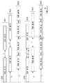
<読取タイミングと転送タイミング>
次に、図4、図5及び図8を参照して、本実施形態における画像読取タイミングと画像データの転送タイミングについて説明する。図4は、片面読取モードの場合の画像読取タイミングと画像データ転送の関係を示す。また、図5は、両面読取モードの場合の画像読取タイミングと画像データ転送の関係を示す。図8は、比較例と本実施形態における画像読取タイミング及び転送タイミングの比較を示す。
<Reading timing and transfer timing>
Next, the image reading timing and the image data transfer timing in this embodiment will be described with reference to FIGS. 4, 5, and 8. FIG. 4 shows the relationship between image reading timing and image data transfer in the single-sided reading mode. FIG. 5 shows the relationship between image reading timing and image data transfer in the duplex reading mode. FIG. 8 shows a comparison of image reading timing and transfer timing in the comparative example and this embodiment.
まず図4の片面読取モードでは、片面(表面)のみを読み取るため第1の画像読取部125だけを使用する。図4に示す401は画像読取タイミングを示す。402は読み取った画像データの転送タイミングを示す。片面読取モードの画像を読み取る走査速度すなわち原稿の搬送速度はV1(mm/msec)であり、ローラ109における画像読取位置での先行原稿の後端通過から後続原稿の先端通過までの紙間時間はα(msec)である。つまり、ローラ109における画像読取位置での先行原稿の後端と後続原稿の先端の原稿間距離(第1の原稿間距離)X1(mm)は、X1(mm)=V1×αとなる。読み取られた画像データは、画像メモリ部139へ一時保持された後に、順次画像出力部140へ出力される。したがって、画像出力部140における画像データのタイミングは、画像読取タイミングよりもTa(msec)遅れて出力され、画像出力部140におけるデータ間隔(第1の時間間隔)はT1(msec)となる。図4においてデータ間隔がT1となる理由は、画像出力部140から画像処理部141へデータ転送する際に、画像処理ブロックでの処理時間が必要となっているためである。したがって、データ間隔T1には、読取位置における紙間時間αに画像処理ブロックでの遅延時間が含まれている。ここで、紙間とは、第1および第2の画像読取部125、124の読取位置における、先行する原稿の後端と後続する次の原稿の先端との間隔である。したがって、紙間時間とは、その間隔を時間で表したものである。また、紙間距離とは、その間隔を距離で表したものである。また、読取位置とは、第1の画像読取部125であればローラ109と原稿台ガラス122が接している位置を示す。一方、第2の画像読取部124であれば、読取位置とは、ローラ111と裏面読取用ガラス123が接している位置を示す。
First, in the single-sided reading mode of FIG. 4, only the first
次に、図5を参照して両面読取時のタイミングについて説明する。501は表面の画像読取タイミングを示す。502は裏面の画像読取タイミングを示す。503は読み取った画像データの転送タイミングを示す。両面読取時の場合には、第1の画像読取部125における走査速度を、第2の画像読取部124に合わせるため、表面側及び裏面側の走査速度はV2(mm/msec)となる。つまり、両面読取時には、片面読取時の走査速度V1よりも走査速度が遅くなる。これにより、第1及び第2の画像読取部125、124における走査速度がV2となり、自動原稿搬送装置101はV2の速度に従って原稿を搬送する。また、本実施形態では、両面読取時において、ローラ109、111における画像読取位置での紙間距離X2(第2の原稿間距離)が、片面読取時の間隔X1よりも狭くなるように設定する。原稿搬送制御としては、紙間時間β(msec)がX1>X2となるように、つまり、β<(V1×α)/V2の関係式が成り立つように紙間を制御する。図5においてデータ間隔(第2の時間間隔)T2は、画像出力部140から画像処理部141へデータ転送する際の、画像処理ブロックでの処理時間であり、T2(msec)には、読取位置における紙間時間βの遅延時間が含まれない。両面の画像を同時に読み取る場合には、読取位置で発生する紙間時間βは画像メモリ部139で吸収され、画像出力部140での画像転送の遅延時間には含まれなくなるからである。
Next, the timing at the time of double-sided reading will be described with reference to FIG.
次に、図8を参照して、本実施形態と比較例との両面読取時におけるタイミングの差異について説明する。タイミングチャート800については、本実施形態に係る図5のタイミングチャートと同様であるため説明を省略する。タイミングチャート810は、比較例となる両面読取時のタイミングチャートである。801は表面の画像読取タイミングを示す。802は裏面の画像読取タイミングを示す。803は読み取った画像データの転送タイミングを示す。
Next, with reference to FIG. 8, a difference in timing between the present embodiment and the comparative example at the time of double-sided reading will be described. Since the
比較例のタイミングチャート810は、片面読取モードと両面読取モードとで走査速度をV1からV2へ変更した場合であって、かつ、原稿間距離を変えない場合の各タイミングを示す。一方、本実施形態に係るタイミングチャート800では、図5を用いて説明したように、片面読取モードと両面読取モードとで走査速度をV1からV2へ変更するとともに、原稿間距離が片面読取モードよりも両面読取モードにおいて短くなるように制御した場合の各タイミングを示す。したがって、図8に示すように、本実施形態における両面読取モードの紙間時間がβ(msec)であるのに対して、比較例での紙間時間γ(msec)は、γ>βとなる。これにより、画像データの転送タイミング803に示すように、裏面の1面目と、表面の2面目との間のデータ間隔T3(msec)が、T3>T2となっている。即ち、比較例においては、本実施形態と比較して、T3−T2(msec)分の時間が無駄に経過していることになる。このように、本実施形態に係る画像読取装置は、タイミングチャート800に示すように、両面読取モードに適合した原稿走査速度で読み取りを行う場合は、原稿間距離を(画像データ転送処理が可能な範囲内で)片面読取モードよりも短くしている。これにより、本画像読取装置は、原稿読取生産性を向上させることができる。
A
<搬送制御構成>
次に、図6を参照して、自動原稿搬送装置101の制御構成について説明する。CPU138は原稿搬送制御部154とデータバス153で接続されている。原稿搬送制御部154は、原稿を搬送するための搬送モータM1、レジモータM2、リードモータM3を制御する。また、原稿搬送制御部154は、原稿搬送タイミングを生成するための紙後端検知センサS1、レジセンサS2、リードセンサS3からの信号を受信し、CPU138へセンサの状態を伝える。給紙クラッチCLは、原稿ピックアップローラ104へ搬送モータM1の駆動を原稿給紙トレイ102より原稿給紙する際に伝達するために設けられ、原稿搬送制御部154によって駆動制御される。搬送モータM1は、ローラ105、106を駆動する。レジモータM2は、ローラ107を駆動する。リードモータM3は、ローラ108、109、110、111、112、113を駆動する。
<Conveyance control configuration>
Next, the control configuration of the
<搬送タイミング>
次に、図7を参照して、原稿搬送制御タイミングについて説明する。図7に示す701は給紙クラッチCLの駆動タイミングを示す。702は搬送モータM1の駆動タイミングを示す。703はレジモータM2の駆動タイミングを示す。リードモータM3の駆動タイミングを示す。705は紙後端検知センサS1の検知タイミングを示す。706はレジセンサS2の検知タイミングを示す。707はリードセンサS3の検知タイミングを示す。
<Transport timing>
Next, the document conveyance control timing will be described with reference to FIG. 701 shown in FIG. 7 indicates the drive timing of the paper feed clutch CL.
まず、両面読取モードがCPU138に通知されると、原稿搬送制御部154は、搬送モータM1における原稿搬送速度を走査速度V2に合致した速度に設定する。また、原稿搬送制御部154は、搬送モータM1を駆動するとともに、給紙クラッチCLを動作させて1枚目の原稿を給紙する。その後、原稿搬送制御部154は、搬送モータM1をレジセンサS2に紙先端が到達するまで駆動させ、レジセンサS2が紙先端を検知した後に搬送モータM1を停止させる。原稿の給紙を開始してからレジセンサS2によって紙先端が検知されるまでの間、レジモータM2及びリードモータM3は、まだ停止したままである。
First, when the duplex scanning mode is notified to the
次に、原稿搬送制御部154は、搬送モータM1、レジモータM2、リードモータM3を走査速度V2に合致した速度で同時に駆動させる。1枚目の原稿先端が、リードセンサS3に到達すると、そこから予め定められた両面読取時の遅延時間後に表面の画像読取が開始される。さらに、表面の画像読取が開始されたタイミングから予め定められた両面読取時の遅延時間が経過すると、裏面の画像読取が開始される。
Next, the document
その後、1枚目の原稿後端が紙後端検知センサS1を通過すると、原稿搬送制御部154は、給紙クラッチCLを駆動し、2枚目の原稿の給紙を開始する。1枚目の原稿の後端がレジセンサS2を通過すると、原稿搬送制御部154は、レジモータM2の駆動を停止するとともに、搬送モータM1の原稿搬送速度を加速させる。その後、原稿搬送制御部154は、レジローラであるローラ107手前で減速させ、レジセンサS2に2枚目の原稿先端が到達したタイミングで搬送モータM1の駆動を停止する。このタイミングで、先行する1枚目の紙後端は、まだリードセンサS3に到達していない。
Thereafter, when the trailing edge of the first document passes the trailing edge detection sensor S1, the document
リーダセンサS3に1枚目の原稿後端が到達すると、原稿搬送制御部154は、レジモータM2及び搬送モータM1の駆動を同時に開始する。さらに、原稿搬送制御部154は、先行する1枚目の原稿後端と2枚目の原稿先端との紙間距離がローラ118に到達する前にX2になるように、走査速度V2に合致した速度よりも速い速度で原稿を搬送させる。これにより、原稿の紙間は、ローラ118に2枚目の原稿先端が到達する前に、X2となる。紙間がX2になると、原稿搬送制御部154は、搬送モータM1及びレジモータM2を、画像走査速度V2に合致した速度まで減速し、その後リードモータM3にて原稿を搬送させる。このようにして、本実施形態では紙間X2の調整が行われる。
When the trailing edge of the first document reaches the reader sensor S3, the document
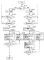
<制御手順>
次に、図3を参照して、本実施形態における画像読取制御の制御手順について説明する。以下で説明する処理は、CPU138によって予め記憶されたプログラムに従って実行される。まず、ステップS101において、CPU138は、設定された原稿の読取モードが片面読取モードであるか、又は両面読取モードであるかを判定する。ここで、読取モードが片面読取モードであった場合はS102に進み、CPU138は、片面読取時の設定を行う。具体的には、CPU138は、画像読取部125のCCDセンサ(又は、CMOSセンサ)の走査速度をV1(mm/sec)に設定する。さらにCPU138は、CCDセンサにおける感光画素の蓄積時間、光源光量、画素読出速度、及びアナログ信号読出処理部133の増幅回路のゲインをそれぞれ所定値に設定する。
<Control procedure>
Next, a control procedure of image reading control in the present embodiment will be described with reference to FIG. The process described below is executed by the
ここで、CCDセンサの蓄積時間とは、CCDセンサのフォトダイオードが受ける光量を電荷として蓄積している時間を示す。また、蓄積時間は、画像の1ラインの主走査読出時間内に設定される。したがって、1ラインの主走査読出時間が速くなれば蓄積時間は短く設定する必要がある。逆に1ラインの主走査読出時間を遅くする場合は感度が上がることになるため蓄積時間を遅くすることができる。また、蓄積時間を変更せずとも、光源の光量を下げることで感度を下げることも可能であるし、CCDセンサでの感度を上げた状態で出力されたアナログ値のゲインを変えることによっても感度を変えることができる。つまり、走査速度を変更する場合は、CCDセンサの感光画素の蓄積時間、光源光量、画素読出速度、及びアナログ信号読出処理部133内の増幅回路のゲインのうち、少なくとも1つの設定を変更することによって画像読取部125の感度を走査速度に合わせることができる。
Here, the accumulation time of the CCD sensor indicates the time during which the amount of light received by the photodiode of the CCD sensor is accumulated as a charge. The accumulation time is set within the main scanning readout time for one line of the image. Therefore, if the main-scan reading time for one line becomes faster, the accumulation time needs to be set shorter. On the other hand, when the main scanning readout time for one line is delayed, the sensitivity increases, so that the accumulation time can be delayed. In addition, it is possible to reduce the sensitivity by reducing the light amount of the light source without changing the accumulation time, and the sensitivity can also be changed by changing the gain of the analog value output with the sensitivity increased by the CCD sensor. Can be changed. In other words, when changing the scanning speed, at least one of the accumulation time of the photosensitive pixels of the CCD sensor, the light source light amount, the pixel reading speed, and the gain of the amplifier circuit in the analog signal
S102で片面読取モードが設定されると、S103において、CPU138は、原稿がセットされているか否かを判定し、セットされていればS104に進む。一方、原稿がセットされていなければS101に戻る。S104において、CPU138は、読取開始指示が与えられたか否かを判定し、与えられるとS105に進む。一方、読取開始指示が与えられていなければS101に戻る。S105において、CPU138は、表面用の画像読取部125におけるCCDセンサのシェーディング動作を実行させる。
When the single-sided reading mode is set in S102, in S103, the
続いて、S106において、CPU138は、自動原稿搬送装置101により原稿を1枚ずつ搬送し、CCDセンサによって原稿表面の画像情報を読み取らせる。ここでの走査速度はV1となる。さらに、S107において、CPU138は、現在読み取っている原稿が読取対象となる最後の原稿であるか否かを判定する。ここで、最後の原稿であれば、現在の読取処理が終了すると本フローチャートの処理を終了し、通常のスタンバイモードに戻る。一方、まだ読取対象の原稿が残っていれば、S108に進む。S108において、CPU138は、先行する1枚目の原稿後端と2枚目の原稿先端との紙間が、読取位置(ローラ109の位置)においてX1(片面読取時の紙間)となるように2枚目の原稿の搬送速度を調整し、S106に処理を戻す。
Subsequently, in S106, the
このように、片面読取モードにおいては、CCDセンサ(又はCMOSセンサ)における走査速度が、予め設定されている第2の画像読取部124におけるCCDセンサ(又はCMOSセンサ)よりも速い走査速度V1(mm/sec)に設定される。これにより、両面読取モードの走査速度V2よりも速い走査速度V1で原稿の読み取りを行なうことができる。
As described above, in the single-sided reading mode, the scanning speed V1 (mm) of the CCD sensor (or CMOS sensor) is higher than that of the CCD sensor (or CMOS sensor) of the second
一方、S101で両面読取モードと判定すると、S109に進み、CPU138は、両面読取時の設定を行う。具体的には、CPU138は、第1の画像読取部125におけるCCDセンサの走査速度を、第2の画像読取部におけるCCDセンサの走査速度V2(mm/sec)に設定する。さらに、CPU138は、CCDセンサの感光画素の蓄積時間、光源光量、画素読出速度、及びアナログ信号読出処理部133内の増幅回路のゲインをそれぞれ所定値に設定する。
On the other hand, if it is determined in S101 that the duplex scanning mode is selected, the process proceeds to S109, and the
S109で片面読取モードが設定されると、S110において、CPU138は、原稿がセットされているか否かを判定し、セットされていればS111に進む。一方、原稿がセットされていなければS101に戻る。S111において、CPU138は、読取開始指示が与えられたか否かを判定し、与えられるとS112に進む。一方、読取開始指示が与えられていなければS101に戻る。S112において、CPU138は、表面用の画像読取部125におけるCCDセンサと、裏面用の画像読取部124におけるCCDセンサとのシェーディング動作を実行させる。
When the single-sided reading mode is set in S109, in S110, the
続いて、S113において、CPU138は、自動原稿搬送装置101により原稿を1枚ずつ搬送し、画像読取部125のCCDセンサによって原稿表面の画像情報を読み取らせる。ここでの走査速度はV2となる。さらに、S114において、CPU138は、原稿がローラ111まで搬送されて第2の画像読取部124の読取位置まで到達したときに、原稿裏面の画像を画像読取部124によって実行させる。さらに、S115において、CPU138は、現在読み取っている原稿が読取対象となる最後の原稿であるか否かを判定する。ここで、最後の原稿であれば、現在の読取処理が終了すると本フローチャートの処理を終了し、通常のスタンバイモードに戻る。一方、読取対象の原稿が残っていれば、S116に進む。S116において、CPU138は、先行する1枚目の原稿後端と2枚目の原稿先端との紙間が、読取位置(ローラ109の位置)においてX2(両面読取時の紙間)となるように2枚目の原稿の搬送速度を調整し、S113に処理を戻す。
Subsequently, in S113, the
このように、両面読取モードにおいては、原稿の搬送速度がローラ109からローラ111にかけて一定であるため、第1の画像読取部125におけるCCDセンサの走査速度を第2の画像読取部124におけるCCDセンサの走査速度V2(mm/sec)に合わせる。但し、第1の画像読取部125のCCDセンサの走査速度をCCDセンサ単独での走査速度V1(mm/sec)からV2へ落とす場合、見かけ上の1画素あたりの感度はV1時よりも上がる。したがって、読取制御部134は、S109において、V1時と同等の画像が得られるように、画像読取センサ部121のCCDドライバに走査速度の減少分だけCCDセンサの感光画素の蓄積時間を短く調整する。或いは、読取制御部134は、走査速度の減少分だけ光源光量を調整するか、画素の読出速度を走査速度の減少に対応するだけ小さくするか、又は、アナログ信号読出処理部133内の増幅回路のゲインを小さくするように、S109において設定する。
As described above, in the double-sided reading mode, since the document conveyance speed is constant from the
以上説明したように、本実施形態に係る画像読取装置100は、片面読取モードの場合には、第1の画像読取部125における走査速度を第1の走査速度に制御するとともに、原稿間距離を第1の原稿間距離に制御する。一方、両面読取モードの場合には、画像読取装置100は、第1の画像読取部125及び第2の画像読取部124における走査速度を、第1走査速度よりも遅い第2走査速度に制御するとともに、原稿間距離を第1の原稿間距離よりも短い第2の原稿間距離に制御する。さらに、画像読取装置100は、画像読取部125、124によって原稿から読み取られた画像データを画像メモリ等に一時的に記憶し、片面読取モードの場合には、画像メモリに記憶された表面の画像データを第1の時間間隔で出力する。一方、両面読取モードの場合には、画像読取装置100は、画像メモリに記憶された表面と裏面との画像データを交互に切り替えながら第1の時間間隔よりも遅い第2の時間間隔で出力する。このように、本実施形態に係る画像読取装置は、通常の画像読取部125に加えて、比較的低速な走査速度を有し、原稿の裏面を読み取る画像読取部124を設けることにより、装置の大型化及びコストの増大を抑制し、原稿の両面を同時に読み取ることができる。さらに、本画像読取装置は、片面読取モードの紙間と比較して、両面読取モードの紙間を狭くすることにより、読取生産性を向上することができる。
As described above, in the single-sided reading mode, the
Claims (6)
前記搬送手段によって第1の走査速度及び前記第1の走査速度よりも遅い第2の走査速度のいずれかで搬送されている原稿の第1面の画像を読み取る第1の画像読取手段と、
前記搬送手段によって前記第2の走査速度で搬送されている原稿の前記第1面の裏面となる第2面の画像を読み取る第2の画像読取手段と、
原稿の片面を読み取る片面読取モードの場合には、前記搬送手段により複数枚の原稿を第1の原稿間距離かつ前記第1の走査速度で搬送させ、原稿の両面を読み取る両面読取モードの場合には、前記搬送手段により複数枚の原稿を前記第1の原稿間距離よりも短い第2の原稿間距離かつ前記第2の走査速度で搬送させる制御手段と
を備えることを特徴とする画像読取装置。 Conveying means for continuously conveying a plurality of documents at a predetermined document distance;
First image reading means for reading an image on a first surface of a document conveyed by the conveying means at either a first scanning speed or a second scanning speed that is slower than the first scanning speed;
A second image reading means for reading an image on a second surface which is the back surface of the first surface of the document being conveyed at the second scanning speed by the conveying means;
In the single-sided reading mode in which one side of the original is read, a plurality of originals are conveyed by the conveying unit at the first inter-document distance and the first scanning speed, and in the double-sided reading mode in which both sides of the original are read. Comprises: a control means for transporting a plurality of documents by the transport means at a second inter-original distance shorter than the first inter-document distance and at the second scanning speed. .
前記片面読取モードの場合には前記記憶手段に記憶された前記第1面から読み取られた画像データを第1の時間間隔で出力し、前記両面読取モードの場合には前記記憶手段に記憶された前記第1面から読み取られた画像データと前記第2面から読み取られた画像データとを交互に切り替えながら前記第1の時間間隔よりも短い第2の時間間隔で出力する画像出力手段と
をさらに備えることを特徴とする請求項1に記載の画像読取装置。 Storage means for temporarily storing image data read from a document by the first image reading means and the second image reading means;
In the case of the single-sided reading mode, the image data read from the first surface stored in the storage unit is output at a first time interval, and in the case of the double-sided reading mode, the image data is stored in the storage unit. Image output means for outputting the image data read from the first surface and the image data read from the second surface alternately at a second time interval shorter than the first time interval while alternately switching the image data read from the second surface; The image reading apparatus according to claim 1, further comprising:
原稿に光を照射する照射手段と、
原稿から反射された反射光を受光し、受光した光量を示すアナログ画像信号を出力する受光手段と、
前記受光手段から出力された前記アナログ画像信号をデジタル画像信号に変換し、原稿から読み取った画像データとして出力する変換手段とを備え、
前記制御手段は、
前記両面読取モードと前記片面読取モードとで、前記照射手段の照度、前記受光手段における感光画素の蓄積時間、及び前記変換手段に設けられた増幅回路のゲインのうち、少なくとも1つを変更することを特徴とする請求項1又は2に記載の画像読取装置。 The first image reading means includes
Irradiating means for irradiating the document with light;
A light receiving means for receiving reflected light reflected from the document and outputting an analog image signal indicating the received light quantity;
Conversion means for converting the analog image signal output from the light receiving means into a digital image signal and outputting it as image data read from a document;
The control means includes
At least one of the illuminance of the irradiation unit, the photosensitive pixel accumulation time in the light receiving unit, and the gain of the amplification circuit provided in the conversion unit is changed between the double-sided reading mode and the single-sided reading mode. The image reading apparatus according to claim 1 or 2.
前記第1の走査速度をV1(mm/msec)とし、前記第2の走査速度をV2(mm/msec)とし、前記片面読取モードにおける先行原稿の後端通過から後続原稿の先端通過までの時間をα(msec)とし、前記両面読取モードにおける先行原稿の後端通過から後続原稿の先端通過までの時間をβ(msec)とすると、β<(V1×α)/V2の関係式が成り立つように前記第2の原稿間距離を制御することを特徴とする請求項1乃至4の何れか1項に記載の画像読取装置。 The control means includes
The first scanning speed is set to V1 (mm / msec), the second scanning speed is set to V2 (mm / msec), and the time from the trailing edge passage of the preceding document to the leading edge of the succeeding document in the single-sided scanning mode. Is α (msec), and β (msec) is the time from the trailing edge passage of the preceding document to the leading edge of the succeeding document in the double-sided reading mode, the relational expression β <(V1 × α) / V2 is satisfied. The image reading apparatus according to claim 1, wherein the distance between the second originals is controlled.
制御手段が、原稿の片面を読み取る片面読取モードの場合には、前記搬送手段により複数枚の原稿を第1の原稿間距離かつ前記第1の走査速度で搬送させ、原稿の両面を読み取る両面読取モードの場合には、前記搬送手段により複数枚の原稿を前記第1の原稿間距離よりも短い第2の原稿間距離かつ前記第2の走査速度で搬送させる制御ステップを実行することを特徴とする画像読取装置の制御方法。 A conveying unit that conveys a plurality of documents continuously at a predetermined distance between the originals, and a first scanning speed and a second scanning speed that is slower than the first scanning speed are conveyed by the conveying unit. A first image reading unit that reads an image on a first side of a document that is being scanned, and an image on a second side that is the back side of the first side of the document that is being conveyed at the second scanning speed by the conveying unit. A second image reading unit for reading the image reading apparatus,
When the control unit is in a single-sided reading mode for reading one side of a document, the conveyance unit transports a plurality of documents at a first inter-document distance and the first scanning speed, and reads both sides of the document. In the case of the mode, a control step is performed in which a plurality of documents are conveyed by the conveying means at a second inter-original distance shorter than the first inter-original distance and at the second scanning speed. For controlling the image reading apparatus.
Priority Applications (2)
| Application Number | Priority Date | Filing Date | Title |
|---|---|---|---|
| JP2010022521A JP5658464B2 (en) | 2010-02-03 | 2010-02-03 | Image reading apparatus and control method thereof |
| US13/005,405 US8477387B2 (en) | 2010-02-03 | 2011-01-12 | Image reading apparatus and method for controlling the same |
Applications Claiming Priority (1)
| Application Number | Priority Date | Filing Date | Title |
|---|---|---|---|
| JP2010022521A JP5658464B2 (en) | 2010-02-03 | 2010-02-03 | Image reading apparatus and control method thereof |
Publications (3)
| Publication Number | Publication Date |
|---|---|
| JP2011160362A JP2011160362A (en) | 2011-08-18 |
| JP2011160362A5 JP2011160362A5 (en) | 2013-03-21 |
| JP5658464B2 true JP5658464B2 (en) | 2015-01-28 |
Family
ID=44341435
Family Applications (1)
| Application Number | Title | Priority Date | Filing Date |
|---|---|---|---|
| JP2010022521A Active JP5658464B2 (en) | 2010-02-03 | 2010-02-03 | Image reading apparatus and control method thereof |
Country Status (2)
| Country | Link |
|---|---|
| US (1) | US8477387B2 (en) |
| JP (1) | JP5658464B2 (en) |
Families Citing this family (15)
| Publication number | Priority date | Publication date | Assignee | Title |
|---|---|---|---|---|
| KR101356649B1 (en) * | 2007-07-24 | 2014-02-03 | 삼성전자주식회사 | Image reading apparatus and image forming apparatus having the same |
| JP5278413B2 (en) * | 2010-11-30 | 2013-09-04 | ブラザー工業株式会社 | Image reading apparatus and program used therefor |
| JP5957820B2 (en) * | 2011-07-27 | 2016-07-27 | 富士ゼロックス株式会社 | Image reading apparatus and program |
| US8964260B2 (en) * | 2012-10-17 | 2015-02-24 | Samsung Electronics Co., Ltd. | Method of controlling scan speed of scanner including automatic document feeder and scanner performing the same |
| JP6206315B2 (en) * | 2014-04-28 | 2017-10-04 | 京セラドキュメントソリューションズ株式会社 | Scanner device and image forming apparatus |
| JP6095634B2 (en) | 2014-11-25 | 2017-03-15 | 京セラドキュメントソリューションズ株式会社 | Image reading apparatus, image forming apparatus, and image reading method |
| JP6080833B2 (en) * | 2014-11-28 | 2017-02-15 | 京セラドキュメントソリューションズ株式会社 | Image forming apparatus and image forming method |
| JP6354664B2 (en) * | 2015-05-29 | 2018-07-11 | 京セラドキュメントソリューションズ株式会社 | Image reading apparatus and image forming apparatus |
| US9596372B2 (en) | 2015-07-29 | 2017-03-14 | Kabushiki Kaisha Toshiba | Image processing apparatus, image processing method and image forming apparatus |
| JP2017046291A (en) | 2015-08-28 | 2017-03-02 | キヤノン株式会社 | Image forming apparatus |
| JP6745602B2 (en) * | 2016-02-15 | 2020-08-26 | キヤノン株式会社 | Image reading apparatus and control method thereof |
| JP2018148366A (en) | 2017-03-03 | 2018-09-20 | キヤノン株式会社 | Image formation device |
| CN111149344B (en) * | 2017-10-05 | 2021-11-30 | 三菱电机株式会社 | Reading device and identification device |
| JP7309543B2 (en) * | 2019-09-12 | 2023-07-18 | キヤノン株式会社 | IMAGE PROCESSING DEVICE, CONTROL METHOD THEREOF, AND PROGRAM |
| JP2021125829A (en) * | 2020-02-06 | 2021-08-30 | キヤノン株式会社 | Manuscript reading device and feed control method |
Family Cites Families (9)
| Publication number | Priority date | Publication date | Assignee | Title |
|---|---|---|---|---|
| JPH0922169A (en) * | 1995-07-04 | 1997-01-21 | Canon Inc | Copying device |
| JP3634597B2 (en) * | 1997-11-07 | 2005-03-30 | キヤノン株式会社 | Image reading apparatus, copying machine, and system |
| US6438350B1 (en) * | 1999-04-26 | 2002-08-20 | Canon Kabushiki Kaisha | Image reading apparatus and image forming apparatus |
| US6242784B1 (en) * | 1999-06-28 | 2001-06-05 | Intersil Corporation | Edge termination for silicon power devices |
| US7042591B1 (en) * | 1999-07-30 | 2006-05-09 | Canon Kabushiki Kaisha | Image exposure apparatus and image forming apparatus |
| JP2004040312A (en) * | 2002-07-01 | 2004-02-05 | Canon Inc | Image reading apparatus and control method thereof, and image forming apparatus |
| JP2008312033A (en) * | 2007-06-15 | 2008-12-25 | Konica Minolta Business Technologies Inc | Image reader |
| JP2009153052A (en) * | 2007-12-21 | 2009-07-09 | Canon Inc | Document reading apparatus |
| JP5409149B2 (en) | 2009-07-10 | 2014-02-05 | キヤノン株式会社 | Image reading device |
-
2010
- 2010-02-03 JP JP2010022521A patent/JP5658464B2/en active Active
-
2011
- 2011-01-12 US US13/005,405 patent/US8477387B2/en active Active
Also Published As
| Publication number | Publication date |
|---|---|
| US20110188095A1 (en) | 2011-08-04 |
| US8477387B2 (en) | 2013-07-02 |
| JP2011160362A (en) | 2011-08-18 |
Similar Documents
| Publication | Publication Date | Title |
|---|---|---|
| JP5658464B2 (en) | Image reading apparatus and control method thereof | |
| EP2760191B1 (en) | Image reading apparatus, image forming apparatus, and image reading method | |
| JP4168960B2 (en) | Image reading device, image reading unit, light irradiation device | |
| US8767268B2 (en) | Image reading apparatus, image forming apparatus, and shading correction method | |
| US8605319B2 (en) | Image reading apparatus capable of reading images of both sides of a document | |
| JP2013042377A (en) | Image reading device, and image forming apparatus | |
| JP4677420B2 (en) | Image reading device | |
| JP5862294B2 (en) | Image reading apparatus, automatic document feeder, and image forming apparatus | |
| US8400689B2 (en) | Image reading apparatus | |
| JP4979445B2 (en) | Document reading apparatus and data transfer method thereof | |
| JP2004357190A (en) | Image reading apparatus | |
| US11290669B2 (en) | Image reading apparatus and image forming apparatus | |
| EP1202551B1 (en) | Both-side document reading apparatus and both-side document reading method | |
| US20180265313A1 (en) | Sheet feeding sub tray, sheet conveying device, image reading device, and image forming apparatus | |
| JP2004040311A (en) | Image reading apparatus and control method thereof, and image forming apparatus | |
| JP6344330B2 (en) | Image reading apparatus and image forming apparatus having the same | |
| JP2007281718A (en) | Image reader | |
| JP4412070B2 (en) | Image reading apparatus and image data correction method | |
| JP5910088B2 (en) | Image reading apparatus and image forming apparatus | |
| JP4872369B2 (en) | Image reading device | |
| JP6098173B2 (en) | Imaging apparatus, image reading apparatus, and image forming apparatus | |
| JP4367079B2 (en) | Image reading device | |
| JP2008312033A (en) | Image reader | |
| JP2009164869A (en) | Image reading device | |
| JP2004040312A (en) | Image reading apparatus and control method thereof, and image forming apparatus |
Legal Events
| Date | Code | Title | Description |
|---|---|---|---|
| A521 | Request for written amendment filed |
Free format text: JAPANESE INTERMEDIATE CODE: A523 Effective date: 20130131 |
|
| A621 | Written request for application examination |
Free format text: JAPANESE INTERMEDIATE CODE: A621 Effective date: 20130131 |
|
| A977 | Report on retrieval |
Free format text: JAPANESE INTERMEDIATE CODE: A971007 Effective date: 20131225 |
|
| A131 | Notification of reasons for refusal |
Free format text: JAPANESE INTERMEDIATE CODE: A131 Effective date: 20140124 |
|
| A521 | Request for written amendment filed |
Free format text: JAPANESE INTERMEDIATE CODE: A523 Effective date: 20140325 |
|
| TRDD | Decision of grant or rejection written | ||
| A01 | Written decision to grant a patent or to grant a registration (utility model) |
Free format text: JAPANESE INTERMEDIATE CODE: A01 Effective date: 20141031 |
|
| A61 | First payment of annual fees (during grant procedure) |
Free format text: JAPANESE INTERMEDIATE CODE: A61 Effective date: 20141128 |
|
| R151 | Written notification of patent or utility model registration |
Ref document number: 5658464 Country of ref document: JP Free format text: JAPANESE INTERMEDIATE CODE: R151 |