EP3964046A1 - Erntevorsatz - Google Patents
Erntevorsatz Download PDFInfo
- Publication number
- EP3964046A1 EP3964046A1 EP21189061.1A EP21189061A EP3964046A1 EP 3964046 A1 EP3964046 A1 EP 3964046A1 EP 21189061 A EP21189061 A EP 21189061A EP 3964046 A1 EP3964046 A1 EP 3964046A1
- Authority
- EP
- European Patent Office
- Prior art keywords
- harvesting
- unit
- cap
- elements
- rotation
- Prior art date
- Legal status (The legal status is an assumption and is not a legal conclusion. Google has not performed a legal analysis and makes no representation as to the accuracy of the status listed.)
- Granted
Links
Images

Classifications
-
- A—HUMAN NECESSITIES
- A01—AGRICULTURE; FORESTRY; ANIMAL HUSBANDRY; HUNTING; TRAPPING; FISHING
- A01D—HARVESTING; MOWING
- A01D45/00—Harvesting of standing crops
- A01D45/02—Harvesting of standing crops of maize, i.e. kernel harvesting
- A01D45/021—Cornheaders
-
- A—HUMAN NECESSITIES
- A01—AGRICULTURE; FORESTRY; ANIMAL HUSBANDRY; HUNTING; TRAPPING; FISHING
- A01D—HARVESTING; MOWING
- A01D34/00—Mowers; Mowing apparatus of harvesters
- A01D34/01—Mowers; Mowing apparatus of harvesters characterised by features relating to the type of cutting apparatus
- A01D34/412—Mowers; Mowing apparatus of harvesters characterised by features relating to the type of cutting apparatus having rotating cutters
- A01D34/63—Mowers; Mowing apparatus of harvesters characterised by features relating to the type of cutting apparatus having rotating cutters having cutters rotating about a vertical axis
- A01D34/64—Mowers; Mowing apparatus of harvesters characterised by features relating to the type of cutting apparatus having rotating cutters having cutters rotating about a vertical axis mounted on a vehicle, e.g. a tractor, or drawn by an animal or a vehicle
- A01D34/66—Mowers; Mowing apparatus of harvesters characterised by features relating to the type of cutting apparatus having rotating cutters having cutters rotating about a vertical axis mounted on a vehicle, e.g. a tractor, or drawn by an animal or a vehicle with two or more cutters
-
- A—HUMAN NECESSITIES
- A01—AGRICULTURE; FORESTRY; ANIMAL HUSBANDRY; HUNTING; TRAPPING; FISHING
- A01D—HARVESTING; MOWING
- A01D34/00—Mowers; Mowing apparatus of harvesters
- A01D34/01—Mowers; Mowing apparatus of harvesters characterised by features relating to the type of cutting apparatus
- A01D34/412—Mowers; Mowing apparatus of harvesters characterised by features relating to the type of cutting apparatus having rotating cutters
- A01D34/63—Mowers; Mowing apparatus of harvesters characterised by features relating to the type of cutting apparatus having rotating cutters having cutters rotating about a vertical axis
- A01D34/73—Cutting apparatus
- A01D34/736—Flail type
-
- A—HUMAN NECESSITIES
- A01—AGRICULTURE; FORESTRY; ANIMAL HUSBANDRY; HUNTING; TRAPPING; FISHING
- A01D—HARVESTING; MOWING
- A01D34/00—Mowers; Mowing apparatus of harvesters
- A01D34/01—Mowers; Mowing apparatus of harvesters characterised by features relating to the type of cutting apparatus
- A01D34/412—Mowers; Mowing apparatus of harvesters characterised by features relating to the type of cutting apparatus having rotating cutters
- A01D34/63—Mowers; Mowing apparatus of harvesters characterised by features relating to the type of cutting apparatus having rotating cutters having cutters rotating about a vertical axis
- A01D34/81—Casings; Housings
-
- A—HUMAN NECESSITIES
- A01—AGRICULTURE; FORESTRY; ANIMAL HUSBANDRY; HUNTING; TRAPPING; FISHING
- A01D—HARVESTING; MOWING
- A01D34/00—Mowers; Mowing apparatus of harvesters
- A01D34/835—Mowers; Mowing apparatus of harvesters specially adapted for particular purposes
- A01D34/8355—Mowers; Mowing apparatus of harvesters specially adapted for particular purposes for cutting up or crushing remaining standing stalks, e.g. stubble
Definitions
- the present invention relates to a harvesting attachment for use on a self-propelled harvesting machine and a self-propelled harvesting machine equipped with such a harvesting attachment.
- Harvesting attachments which cut the stalks of a crop to be harvested in order to then recover the plant parts remote from the ground, generally including the infructescence, and feed them to threshing or chopping processing by the self-propelled harvester, are known in many configurations.
- a harvesting attachment in which a shredding unit is limited to destroying above-ground parts of the stubble. Complete processing of all stubble is easier and requires less energy here, but only if the shredding unit can be guided close enough to the surface of the earth. However, their mobility relative to the harvesting unit tends to be restricted by the plant residues knocked off and whirled up by the shredding unit.
- One object of the invention is to create a harvesting attachment that enables reliable and complete destruction of the stubble with little use of time and energy.
- a harvesting attachment for a self-propelled harvesting machine with a harvesting unit for cutting and salvaging parts of a plant stand that are distant from the ground and a shredding unit for shredding parts of the plant stand close to the ground that are not salvaged by the harvesting unit, the at least one movably attached to the harvesting unit coupled, surrounded by a housing and supported on the ground during operation.
- a spherical cap scanning the ground contour can be driven in rotation about a vertical axis of rotation and serve as a carrier for a plurality of comminuting elements revolving about a axis of rotation.
- the rotation of the cap makes it easier to glide over uneven ground; by not rotating the cap and shredding elements relative to one another, the structure of the underfloor shredder can be simplified and the likelihood of the rotation being impeded by dirt penetrating between mutually moving parts can be minimized.
- each of the comminution elements is preferably articulated on the circumference of the cap so that it can pivot about an axis parallel to the axis of rotation.
- the underside of the cap is preferably convexly curved without steep flanks. More precisely, the radius of the circumference of the cap on which the comminution elements are arranged should be larger than the distance between the circumference and a lowest point of the cap, measured along the axis of rotation.
- the underside of the dome is preferably spherical or oblate ellipsoidal at least about the axis of rotation.
- the purpose of the underfloor chopper is not to cut the crop stalks that have already been cut by the harvesting unit a second time closer to the ground, but to destroy the structure of the remainder of the stalk so completely that it can no longer be used as a winter shelter for pests.
- Crushing elements with blunt striking surfaces are used for this more suitable than, for example, rotating knives.
- a comminution element can be regarded as blunt in this sense, the radius of curvature of which on a surface that comes into contact with the stubble during operation is greater than 1 mm, preferably greater than 5 mm.
- each comminuting element has a front and a rear impact surface in relation to its direction of rotation.
- this allows the comminution elements to be mounted on the caps without having to take their direction of rotation into account; on the other hand, a crushing element can be turned over and reused when a first striking surface is worn out.
- a PTA coating can also be provided to increase the service life of the cap and/or comminution elements.
- PTA Pulsma Powder Deposition Welding
- the housing can be common to several, preferably two, underfloor shredders.
- the comminution unit can be movably coupled to the harvesting unit by a plurality of links connecting the housing to the harvesting unit be made.
- these links can form a four-bar linkage in order to keep the orientation of the axis of rotation constant in this side view even when the comminution unit moves relative to the harvesting unit.
- the links should be spaced widthwise.
- at least one of the links can be coupled to an actuator in order to be able to raise or lower the comminution unit relative to the harvesting unit or to pivot the axis of rotation about an axis running in the transverse direction of the header.
- the housing may include a top panel through which the axis of rotation extends and walls extending downwardly from edges of the top panel for intercepting stubble fragments produced by the comminution unit. These walls preferably extend below the plane of the perimeter in which the crushing elements are mounted. They are preferably at least partially flexible in order to be able to avoid uneven floors.
- the comminution unit When the shredding elements rotate, they move part of their path in the direction of travel and an opposite part in the opposite direction to the direction of travel. So that they have the necessary speed for comminuting the stubble over their entire path, the comminution unit should be coupled to a traction drive of the harvesting machine in such a way that the rotational speed of the comminution elements is a multiple of the driving speed of the harvesting machine.
- the shredding elements To ensure that all stubble is reliably captured and crushed, including those that are in front of the caps in the direction of travel, the shredding elements must follow one another so quickly that they capture the stubble before they reach the caps.
- the shredding unit should therefore be coupled to a traction drive of the harvesting machine in such a way that The product of the radial expansion of the crushing elements, the number of crushing elements on a cap and the speed of the cap is greater than the driving speed of the harvesting machine.
- Fig.1 shows a front harvesting attachment 1 for attachment to a self-propelled harvesting machine for harvesting corn.
- the components of the harvesting attachment 1 visible in this figure are collectively referred to as harvesting unit 2 here. Tips 3 of a comb extending along the front edge of the header 1 are spaced such that a row of corn plants is caught between two tips 3 and their stalks are fixed in the lateral direction, while they are not visible in the view by rotating knives underneath the tips be clipped a few centimeters above the ground.
- a collection pan 4 into which the crop falls extends behind the comb.
- the crop can - such as when the harvester is a forage harvester - the be whole corn plants; in the case of a combine harvester considered here, it is preferably only the cobs that are fed to the combine harvester by the header, while the stalks are chopped up and deposited on the ground without passing through the combine harvester.
- a screw conveyor 5 rotating in the collecting pan 4 is used to collect the harvested crops in the middle of the collecting pan 4 and feed them through an opening 6 on the back (see Fig. 2 ) of the harvesting machine to which the header 1 is mounted.
- the header 1 shown here is divided in the transverse direction into a central section 7 and two lateral sections 8.
- the lateral sections can be pivoted with the aid of two hydraulic actuators 9 about axes 10 adjacent to an upper edge of the header 1 into a transport position in which they are on the Central section 7 rest. In the transport position, the header 1 is no longer wider than the body of the harvesting machine carrying it, so that the harvester with the header 1 mounted can move on the road.
- the shredding units 11 each have a flat housing with a substantially horizontal top plate 12 and side walls 13 made of sheet steel and a flexible rear wall in the form of a rubber skirt 14 hanging from a rear edge of the top plate 12 .
- the housing is open so that the stubble left behind when the corn stalks are cut by the knives of the harvesting unit 2 can move into the housing of the shredding units 11 .
- a gearbox intended to drive the knives and the auger 5 of the harvesting unit 2 as well as moving elements of the crushing units 11 (which will be described later with reference to figure 5 be described in more detail) to couple to a PTO shaft of the harvesting machine with a predetermined transmission ratio.
- Parts of the transmission are accommodated in housings 15 on both sides of the center section 7, respectively.
- Shafts 16, 17 extending in opposite directions from the housings 15 each drive a comminution unit 11 of the central section 7 and one of the lateral sections 8.
- the shafts 17 of the side sections 8 are detachably plug-connected to an output of the housing 15 in order to enable the above-mentioned pivoting of the side sections 8 into the transport position.
- the shredding units 11 are vertically movable to a limited extent relative to the harvesting unit 2; In order to take account of this mobility, the shafts 16, 17 are coupled at their ends via cardan joints (here concealed in elastic bellows 18) to the transmission or to the comminution unit 11.
- FIG. 3 shows part of the harvesting attachment 1 in a side view, once in an operating position close to the ground and once during a lifting movement, which is carried out by the harvesting machine, for example, when it enters an adjacent headland from a field area that has just been harvested.
- the top plate 12 of the housing lies slightly above a plane in which the knives (here designated 19) of the harvesting unit rotate.
- a cap 20 projecting downwards out of the housing is supported on the floor 21 .
- the crushing unit 11 is connected to the collecting pan 4 via two links 22, 23.
- These links 22, 23 can be parallel and of equal length to allow maintaining the orientation of the crushing unit 11 relative to the ground 21 when the harvesting unit is lifted while maintaining its orientation; in the case shown here, the length and arrangement of the links 22, 23 are selected so that the orientation of the comminution unit 11 does not change when the harvesting unit is raised, although its raising is associated with a slight pivoting movement, as can be seen by comparing the right and left parts of the figure. As long as the cap 20 remains in contact with the ground, the effect of the crushing unit 11 is unchanged.
- the handlebars 22, 23 can be rigid components; in the case shown here, the upper of the two links 23 is formed by an actuator; by varying its length, the crushing unit can be driven to pitch.
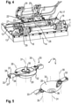
- FIG. 4 shows a perspective view of a comminution unit 11 and its connection to the collecting pan 4.
- a fitting for attachment to the rear of the collecting pan 4 is denoted by 24.
- the link 22 has the shape of a bracket which is articulated at both ends to the fitting part 24 and centrally to the housing of the comminution unit 11 .
- An actuator 25 acts on the fitting part 24 and on the link 22 in order to raise the comminution unit 11 into a protected position closely resting against the collecting pan 4 if necessary.
- the link 23 is provided twice, each on either side of the link 22; the chambers of its double-acting actuators are coupled to one another via hydraulic lines 26 in such a way that the compression of one of the actuators drives the extension of the respective other one, thus enabling the crushing unit 11 to rock. In this way, the orientation of the comminution unit 11 can adapt to the contour of the ground during operation.
- Two bevel gears 27 are mounted on the cover plate 12 of the housing, which are coupled to one another by a shaft 28 and to the shaft 16 or 17 by a further gear 29 .
- the bevel gears 27 each drive an output shaft which extends perpendicularly to the cover plate 12 into the interior of the housing.
- each of these output shafts 30 is non-rotatable with one of the ones already referred to in FIG 3 mentioned caps 20 connected.
- the outside of the spherical cap 20 facing the base 21 is spherically or ellipsoidally curved, with an axis of rotation 31 of the output shaft 30 coinciding with the short axis of the ellipse.
- two comminuting elements 33 are mounted as mirror images of one another in order to form an underfloor shredder 34.
- the connection of the comminuting elements 33 to the cap 20 is articulated with a pivot axis 35 parallel to the axis of rotation 31, so that the comminuting elements 33 can give way when they hit a non-yielding obstacle.
- the radius of the perimeter 32 is less than the distance between the plane defined by the radius 32 and a point 36 at which the axis of rotation 31 crosses the underside of the cap 20 .
- the surface of the calotte 20 therefore always runs at a small angle to the floor 21, so that the calotte 20 can follow a moderately uneven floor surface with certainty.
- the comminuting element 33 When hitting a corn stubble, the comminuting element 33 must not recede but should smash it and shatter it into a large number of fragments. For this purpose, the weight of the crushing element 33 should exceed that of the stubble by a multiple.
- the comminuting element 33 is therefore not a narrow blade, but a squat metal body with an extension of several millimeters or even centimeters in the direction of the axis of rotation.
- the crushing element 33 has an H-like cross-section, which can be derived from a cylindrical basic shape by cutting out a groove 37 on the top and bottom.
- Cap 20 and comminuting element 33 are exposed to considerable frictional stress during operation and should therefore be made of sufficiently wear-resistant steel.
- a hard, durable coating in particular a PTA coating, can be provided on the outside of cap 20 and the striking surfaces of crushing element 33 .
- the cross section of the crushing element 33 is symmetrical with respect to a plane running through the axis of rotation 31 .
- the crushing element 33 thus has two striking surfaces 38, only one of which is used in each case. On the one hand, this facilitates the assembly of the shredding units 11, since the subsequent direction of rotation of the underfloor chopper 34 does not have to be taken into account, and on the other hand, the detachable fastening of the shredding elements 33 shown offers the user the opportunity to turn them over if one of the impact surfaces 38 is worn.
- the expansion of the comminuting element 33 in the radial direction is determined by the requirement that during operation no stubble may reach the cap 20 intact and be pressed to the ground by it, but that it should be reliably hit beforehand by a comminuting element 33 rotating about the axis 30 and shattered Need to become. Consequently, in the time that the harvesting machine needs to cover the length of the comminuting element 33, the area in front of the cap 20 must be swept at least once by a comminuting element 33, i.e.
- the gearboxes of the harvesting machine and header which connect the comminuting unit to the motor of the harvesting machine couple, must ensure a translation in which the product of radial expansion of the crushing elements 33, the number of crushing elements 33 on a cap 20 and the speed of the cap 20 is greater than the driving speed of the harvesting machine.
- the rolling mobility of the comminution unit 11 allows each of the two caps 20 to be kept essentially continuously in contact with the ground 21, so that the comminution elements 33 can grasp and break up the stubble at a constant, small distance from the ground, even if the ground is moderately uneven , so that any remains left in the ground are no longer big enough to serve as a winter shelter for a pest.
Landscapes
- Life Sciences & Earth Sciences (AREA)
- Environmental Sciences (AREA)
- Harvester Elements (AREA)
- Harvesting Machines For Specific Crops (AREA)
Abstract
Description
- Die vorliegende Erfindung betrifft einen Erntevorsatz zur Verwendung an einer selbstfahrenden Erntemaschine sowie eine mit einem solchen Erntevorsatz ausgestattete selbstfahrende Erntemaschine.
- Erntevorsätze, die die Stiele eines zu erntenden Pflanzenbestands kappen, um daraufhin die bodenfernen, im allgemeinen die Fruchtstände umfassenden Pflanzenteile zu bergen und einer Dresch- oder Häckselverarbeitung durch die selbstfahrende Erntemaschine zuzuführen, sind in vielen Ausgestaltungen bekannt. Die nach der Ernte auf dem Acker verbleibenden Stoppeln behindern, auch wenn sie untergepflügt werden, die Aussaat der Folgefrucht. Außerdem können sie Schädlingen wie etwa dem Maiszünsler als Unterschlupf dienen, was zu empfindlichen Ernteeinbußen führen kann, wenn auf derselben oder einer benachbarten Fläche dieselbe Feldfrucht im Folgejahr erneut angebaut wird.
- Die Stoppeln in einem auf die Ernte folgenden Arbeitsgang zu beseitigen ist aufwendig und wenig wirtschaftlich. In
DE 10 2014 219 694 ist daher ein Erntevorsatz für Mais vorgeschlagen worden, der eine Ernteeinheit zum Schneiden und Bergen der bodenfernen Teile einer Maispflanze mit einer Einheit zum Herausziehen und Zerkleinern der Maisstoppeln während der Ernte kombiniert. - Das Herausziehen der Maisstoppeln erfordert hohen Kraftaufwand; gleichzeitig ist es nur dann wirksam, wenn die Stoppeln nahezu vollständig erfasst werden, da eine kleine Zahl intakt bleibender Stoppeln ausreichen kann, um die Wirksamkeit der Maßnahme in Frage zu stellen.
- Aus
EP 2 107 867 B1 ist ein Erntevorsatz bekannt, bei dem eine Zerkleinerungseinheit sich darauf beschränkt, oberirdische Teile der Stoppeln zu zerstören. Hier ist eine vollständige Bearbeitung aller Stoppeln einfacher und mit geringerem Energieaufwand möglich, allerdings nur wenn es gelingt, die Zerkleinerungseinheit dicht genug über der Erdoberfläche zu führen. Deren Beweglichkeit relativ zur Ernteeinheit neigt jedoch dazu, durch die von der Zerkleinerungseinheit abgeschlagenen und aufgewirbelten Pflanzenreste eingeschränkt zu werden. - Eine Aufgabe der Erfindung ist, einen Erntevorsatz zu schaffen, der eine zuverlässige und vollständige Zerstörung der Stoppeln mit geringem Zeit-und Energieeinsatz ermöglicht.
- Die Aufgabe wird zum einen gelöst durch einen Erntevorsatz für eine selbstfahrende Erntemaschine mit einer Ernteeinheit zum Schneiden und Bergen von bodenfernen Teilen eines zu erntenden Pflanzenbestands und einer Zerkleinerungseinheit zum Zerkleinern von von der Ernteeinheit nicht geborgenen bodennahen Teilen des Pflanzenbestands, die wenigstens einen beweglich an die Ernteeinheit gekoppelten, von einem Gehäuse umgebenen und im Betrieb am Boden abgestützten Unterflurhäcksler umfasst. Indem das Gehäuse die von dem Unterflurhäcksler erzeugten Stoppelbruchstücke daran hindert, sich zu verteilen, kann eine Blockade der Zerkleinerungseinheit relativ zur Ernteeinheit vermieden werden, so dass die Zerkleinerungseinheit der Bodenkontur zuverlässig folgen und die Stoppeln vollständig und in für eine vollständige Zerstörung geeigneter Höhe erfassen kann.
- Eine die Bodenkontur abtastende Kalotte kann um eine vertikale Drehachse drehangetrieben sein und als Träger für mehrere um eine Drehachse umlaufende Zerkleinerungselemente dienen. Die Drehung der Kalotte erleichtert ein Hinweggleiten über Bodenunebenheiten; indem Kalotte und Zerkleinerungselemente nicht relativ zueinander rotieren, kann der Aufbau des Unterflurhäckslers vereinfacht und die Wahrscheinlichkeit einer Behinderung der Drehung durch zwischen gegeneinander bewegliche Teile eindringenden Schmutz minimiert werden.
- Um eine Blockade des Unterflurhäckslers durch unbewegliche Hindernisse zu vermeiden, ist vorzugsweise jedes der Zerkleinerungselemente an den Umfang der Kalotte um eine zur Drehachse parallele Achse schwenkbar angelenkt.
- Um das Hinweggleiten über Unebenheiten zu erleichtern, ist die Unterseite der Kalotte vorzugsweise ohne steile Flanken konvex gekrümmt. Genauer gesagt sollte der Radius des Umfangs der Kalotte, an dem die Zerkleinerungselemente angeordnet sind, größer sein als der entlang der Drehachse gemessene Abstand zwischen dem Umfang und einem untersten Punkt der Kalotte.
- Die Unterseite der Kalotte ist vorzugsweise wenigstens um die Drehachse herum sphärisch oder abgeflacht ellipsoidisch.
- Zweck des Unterflurhäckslers ist es nicht, die bereits von der Ernteeinheit gekappten Stiele des Ernteguts ein zweites Mal näher am Boden zu schneiden, sondern die Struktur des Stielrests so vollständig zu zerstören, dass dieser als Winterunterschlupf für Schädlinge nicht mehr brauchbar ist. Dafür ist es wünschenswert, den Stielrest nicht nur in Längsrichtung, sondern auch in Richtung seines Umfangs in mehrere Fragmente zu zerlegen, so dass ggf. weiche innere Teile des Stiels großflächig der Witterung ausgesetzt sind. Hierfür sind Zerkleinerungselemente mit stumpfen Schlagflächen besser geeignet als etwa rotierende Messer. Als stumpf in diesem Sinne kann insbesondere eine Zerkleinerungselement gelten, dessen Krümmungsradius an einer im Betrieb mit den Stoppeln in Kontakt tretenden Oberfläche größer als 1 mm, vorzugsweise größer als 5 mm ist.
- Vorteilhaft ist ferner, wenn jedes Zerkleinerungselement in Bezug auf seine Drehrichtung je eine vordere und eine hintere Schlagfläche aufweist. Dies erlaubt es zum einen, die Zerkleinerungselemente an den Kalotten zu montieren, ohne dabei deren Drehsinn berücksichtigen zu müssen; zum anderen kann ein Zerkleinerungselement, wenn eine erste Schlagfläche abgenutzt ist, gewendet und weiterbenutzt werden.
- Zur Erhöhung der Standzeit von Kalotte und/oder Zerkleinerungselementen kann ferner eine PTA-Beschichtung vorgesehen werden. PTA (Plasma-Pulver-Auftragschweißen) ist ein Schweißverfahren, das eine metallurgische Verbindung der Beschichtung mit dem Grundwerkstoff ermöglicht; ferner können mit dieser Technik Karbid-Oberflächenschichten hoher Härte erzeugt werden.
- Das Gehäuse kann mehreren, vorzugsweise zwei, Unterflurhäckslern gemeinsam sein.
- Indem die Kalotten beider Unterflurhäcksler mit dem Boden in Kontakt gebracht werden, kann eine Wankbewegung der Zerkleinerungseinheit gesteuert werden, die es den Zerkleinerungselementen ermöglicht, sich einem quer zur Fahrtrichtung abschüssigen Verlauf der Bodenoberfläche anzupassen. Wenn die Zahl der Unterflurhäcksler in jedem Gehäuse zwei ist, dann kann die Kalotte eines jeden mit dem Boden in Kontakt gehalten werden.
- Die bewegliche Kopplung der Zerkleinerungseinheit an die Ernteeinheit kann durch mehrere das Gehäuse mit der Ernteeinheit verbindende Lenker hergestellt sein. Diese Lenker können in einer Seitenansicht ein Viergelenk bilden, um die Orientierung der Drehachse in dieser Seitenansicht auch dann konstant zu halten, wenn sich die Zerkleinerungseinheit relativ zur Ernteeinheit bewegt. Um eine Gierdrehung der Zerkleinerungseinheit in Kontakt mit einem Hindernis zu unterbinden, sollten die Lenker in Breitenrichtung beabstandet sein. Ferner kann wenigstens einer der Lenker mit einem Stellglied gekoppelt sein, um bei Bedarf die Zerkleinerungseinheit relativ zur Ernteeinheit anheben oder senken oder die Drehachse um eine in Querrichtung des Erntevorsatzes verlaufende Achse schwenken zu können.
- Das Gehäuse kann eine Deckenplatte, durch die sich die Drehachse erstreckt, und sich von Rändern der Deckenplatte aus nach unten erstreckende Wände zum Abfangen der von der Zerkleinerungseinheit erzeugten Stoppelfragmente aufweisen. Diese Wände erstrecken sich vorzugsweise bis unter die Ebene des Umfangs, in der die Zerkleinerungselemente befestigt sind. Vorzugsweise sind sie wenigstens zum Teil flexibel, um Bodenunebenheiten ausweichen zu können.
- Wenn die Zerkleinerungselemente rotieren, bewegen sie sich auf einem Teil ihrer Bahn in der Fahrtrichtung und in einem gegenüberliegenden Teil entgegen der Fahrtrichtung. Damit sie auf ihrer gesamten Bahn die zum Zerkleinern der Stoppeln nötige Geschwindigkeit haben, sollte die Zerkleinerungseinheit an einen Fahrantrieb der Erntemaschine so gekoppelt sein, dass die Umlaufgeschwindigkeit der Zerkleinerungselemente ein Mehrfaches der Fahrgeschwindigkeit der Erntemaschine beträgt.
- Damit alle Stoppeln zuverlässig erfasst und zerkleinert werden, auch solche, die sich in Fahrtrichtung vor den Kalotten befinden, müssen die Zerkleinerungselemente so schnell aufeinander folgen, dass sie die Stoppeln erfassen, bevor sie die Kalotten erreichen. Die Zerkleinerungseinheit sollte daher an einen Fahrantrieb der Erntemaschine so gekoppelt sein, dass das Produkt aus radialer Ausdehnung der Zerkleinerungselemente, Anzahl der Zerkleinerungselemente an einer Kalotte und Drehzahl der Kalotte größer ist als die Fahrgeschwindigkeit der Erntemaschine.
- Weitere Merkmale und Vorteile der Erfindung ergeben sich aus der nachfolgenden Beschreibung von Ausführungsbeispielen unter Bezugnahme auf die beigefügten Figuren. Es zeigen:
- Fig. 1
- einen erfindungsgemäßen Erntevorsatz in einer Ansicht schräg von vorn;
- Fig. 2
- den Erntevorsatz in einer Ansicht schräg von hinten;
- Fig. 3
- Seitenansichten des Erntevorsatzes in einer Betriebsstellung und während des Anhebens aus der Betriebsstellung;
- Fig. 4
- eine Detailansicht einer Zerkleinerungseinheit an der Rückseite des Erntevorsatzes; und
- Fig.5
- einen Unterflurhäcksler der Zerkleinerungseinheit.
-
Fig.1 zeigt einen Erntevorsatz 1 zur Anbringung an einer selbstfahrenden Erntemaschine für die Maisernte in einer Ansicht schräg von vorn. Die in dieser Fig. sichtbaren Komponenten des Erntevorsatzes 1 werden hier zusammenfassend als Ernteeinheit 2 bezeichnet. Spitzen 3 eines sich entlang der Vorderkante des Erntevorsatzes 1 erstreckenden Kamms sind so beabstandet, dass zwischen zwei Spitzen 3 jeweils eine Reihe von Maispflanzen erfasst und ihre Stiele in seitlicher Richtung fixiert werden, während sie von unterhalb der Spitzen rotierenden, in der Ansicht nicht sichtbaren Messern wenige Zentimeter über dem Boden gekappt werden. Hinter dem Kamm erstreckt sich eine Auffangwanne 4, in die das Erntegut hineinfällt. Das Erntegut können ― so etwa wenn die Erntemaschine ein Feldhäcksler ist ― die vollständigen Maispflanzen sein; im hier betrachteten Fall eines Mähdreschers sind es vorzugsweise nur die Kolben, die durch den Erntevorsatz dem Mähdrescher zugeführt werden, während die Stängel zerkleinert und auf dem Boden abgelegt werden, ohne den Mähdrescher zu durchlaufen. - Eine in der Auffangwanne 4 rotierende Förderschnecke 5 dient dazu, das Erntegut in der Mitte der Auffangwanne 4 zusammenzuraffen und über eine rückseitige Öffnung 6 (s.
Fig. 2 ) der Erntemaschine zuzuführen, an der der Erntevorsatz 1 montiert ist. - Der hier gezeigte Erntevorsatz 1 ist in Querrichtung unterteilt in einen Mittelabschnitt 7 und zwei seitliche Abschnitte 8. Die seitlichen Abschnitte sind mit Hilfe zweier hydraulischer Stellglieder 9 um zu einer oberen Kante des Erntevorsatzes 1 benachbarte Achsen 10 in eine Transportstellung schwenkbar, in der sie auf dem Mittelabschnitt 7 aufliegen. In der Transportstellung ist der Erntevorsatz 1 nicht mehr breiter als die Karosserie der ihn tragenden Erntemaschine, so dass sich die Erntemaschine mit montiertem Erntevorsatz 1 im Straßenverkehr bewegen kann.
- In der Ansicht der
Fig. 2 sind an einer hinteren unteren Kante des Erntevorsatzes 1 mehrere Zerkleinerungseinheiten 11 zu sehen. Die Zerkleinerungseinheiten 11 haben jeweils ein flaches Gehäuse mit einer im Wesentlichen horizontalen Deckenplatte 12 und Seitenwänden 13 aus Stahlblech und einer flexiblen Rückwand in Form einer Schürze 14 aus Gummi, die von einer rückwärtigen Kante der Deckenplatte 12 herabhängt. An einer in derFig. 2 nicht sichtbaren Vorderseite ist das Gehäuse offen, damit die beim Kappen der Maisstängel durch die Messer der Ernteeinheit 2 zurückgebliebenen Stoppeln in das Gehäuse der Zerkleinerungseinheiten 11 einrücken können. - An der Rückseite der Auffangwanne 4 ist ein Getriebe angebracht, das vorgesehen ist, um die Messer und die Förderschnecke 5 der Ernteeinheit 2 sowie bewegliche Elemente der Zerkleinerungseinheiten 11 (die später anhand von
Fig. 5 noch genauer beschrieben werden) an eine Zapfwelle der Erntemaschine mit einem vorgegebenen Übersetzungsverhältnis zu koppeln. Teile des Getriebes sind jeweils in Gehäusen 15 an beiden Seiten des Mittelabschnitts 7 untergebracht. Von den Gehäusen 15 aus sich in entgegengesetzte Richtungen erstreckende Wellen 16, 17 treiben jeweils eine Zerkleinerungseinheit 11 des Mittelabschnitts 7 sowie eines der seitlichen Abschnitte 8 an. Die Wellen 17 der seitlichen Abschnitte 8 sind mit einem Abtrieb der Gehäuse 15 lösbar steckverbunden, um das oben erwähnte Schwenken der seitlichen Abschnitte 8 in die Transportstellung zu ermöglichen. - Die Zerkleinerungseinheiten 11 sind relativ zur Ernteeinheit 2 in begrenztem Umfang vertikal beweglich; um dieser Beweglichkeit Rechnung zu tragen, sind die Wellen 16, 17, an ihren Enden über (hier in elastischen Bälgen 18 verborgene) Kardangelenke an das Getriebe bzw. an die Zerkleinerungseinheit 11 gekoppelt.
-
Fig. 3 zeigt einen Teil des Erntevorsatzes 1 in Seitenansicht, einmal in einer bodennahen Betriebsstellung und einmal im während einer Anhebebewegung, die von der Erntemaschine beispielsweise ausgeführt wird, wenn sie von einer soeben abgeernteten Feldfläche in ein benachbartes Vorgewende einfährt. In der im linken Teil derFig. 3 gezeigten Betriebsstellung liegt die Deckenplatte 12 des Gehäuses geringfügig oberhalb einer Ebene, in der die (hier mit 19 bezeichneten) Messer der Ernteeinheit rotieren. Eine nach unten aus dem Gehäuse vorstehende Kalotte 20 stützt sich am Boden 21 ab. Die Zerkleinerungseinheit 11 ist mit der Auffangwanne 4 über zwei Lenker 22, 23 verbunden. Diese Lenker 22, 23 können parallel und gleich lang sein, um eine Beibehaltung der Orientierung der Zerkleinerungseinheit 11 relativ zum Boden 21 zu ermöglichen, wenn die Ernteeinheit unter Beibehaltung ihrer Orientierung angehoben wird; im hier dargestellten Fall sind die Länge und Anordnung der Lenker 22, 23 so gewählt, dass sich die Orientierung der Zerkleinerungseinheit 11 beim Anheben der Ernteeinheit nicht ändert, obwohl deren Anhebung, wie bei einem Vergleich des rechten und des linken Teils der Fig. zu erkennen, mit einer leichten Schwenkbewegung verknüpft ist. Solange die Kalotte 20 mit dem Boden in Kontakt bleibt, ist die Wirkung der Zerkleinerungseinheit 11 unverändert. Wenn folglich die Erntemaschine beim Verlassen eines Pflanzenbestandes beginnt, den Erntevorsatz 1 anzuheben, dann hat dies zunächst keine Wirkung auf die Zerkleinerungseinheit 11, und diese kann, wenn die Geschwindigkeit der Anhebung sinnvoll an die Fahrgeschwindigkeit und die Bewegungsfreiheit der Zerkleinerungseinheit 11 angepasst ist, noch während des Anhebens die zuletzt geschnittenen Stoppeln zerstören. - Die Lenker 22, 23 können in sich starre Bauteile sein; im hier gezeigten Fall ist der obere der beiden Lenker 23 durch ein Stellglied gebildet; indem dessen Länge variiert wird, kann die Zerkleinerungseinheit zu einer Nickbewegung angetrieben werden.
-
Fig. 4 zeigt eine perspektivische Ansicht einer Zerkleinerungseinheit 11 und ihrer Verbindung zur Auffangwanne 4. Ein Beschlagteil zur Anbringung an der Rückseite der Auffangwanne 4 ist mit 24 bezeichnet. Der Lenker 22 hat die Form eines Bügels, der an seinen beiden Enden an das Beschlagteil 24 und mittig an das Gehäuse der Zerkleinerungseinheit 11 angelenkt ist. Ein Stellglied 25 greift am Beschlagteil 24 und am Lenker 22 an, um bei Bedarf die Zerkleinerungseinheit 11 in eine geschützte, eng an der Auffangwanne 4 anliegende Stellung anzuheben. Der Lenker 23 ist zweimal, jeweils beiderseits des Lenkers 22 vorgesehen; die Kammern ihrer doppelt wirkenden Stellglieder sind untereinander über Hydraulikleitungen 26 so gekoppelt, dass die Stauchung eines der Stellglieder die Streckung des jeweils anderen antreibt und so eine Wankbewegung der Zerkleinerungseinheit 11 ermöglicht. So kann sich die Orientierung der Zerkleinerungseinheit 11 im Betrieb der Kontur des Bodens anpassen. - Auf der Deckenplatte 12 des Gehäuses sind zwei Winkelgetriebe 27 montiert, die untereinander durch eine Welle 28 und mit der Welle 16 oder 17 durch ein weiteres Getriebe 29 gekoppelt sind. Die Winkelgetriebe 27 treiben jeweils eine Abtriebswelle an, die sich senkrecht zur Deckenplatte 12 ins Innere des Gehäuses erstreckt.
- Wie in
Fig. 5 zu sehen, ist jede dieser Abtriebswellen 30 drehfest mit einer der bereits mit Bezug aufFig. 3 erwähnten Kalotten 20 verbunden. Die dem Boden 21 zugewandte Außenseite der Kalotte 20 ist sphärisch oder rotationsellipsoidisch gewölbt, wobei eine Drehachse 31 der Abtriebswelle 30 mit der kurzen Achse der Ellipse zusammenfällt. An einem Umfang 32 der Kalotte 20 sind zwei Zerkleinerungselemente 33 spiegelbildlich zueinander montiert, um einen Unterflurhäcksler 34 zu bilden. Die Verbindung der Zerkleinerungselemente 33 zur Kalotte 20 ist gelenkig mit einer zur Drehachse 31 parallelen Schwenkachse 35, so dass die Zerkleinerungselemente 33 ausweichen können, wenn sie an ein nicht nachgiebiges Hindernis anschlagen. - Der Radius des Umfangs 32 ist kleiner als der Abstand zwischen der durch den Radius 32 definierten Ebene und einem Punkt 36, an dem die Drehachse 31 die Unterseite der Kalotte 20 kreuzt. Die Oberfläche der Kalotte 20 verläuft daher immer unter einem kleinen Winkel zum Boden 21, so dass die Kalotte 20 einer in Maßen unebenen Bodenoberfläche sicher folgen kann.
- Beim Anschlagen an einen Maisstoppel darf das Zerkleinerungselement 33 nicht zurückweichen, sondern soll diesen zerschlagen und in eine Vielzahl von Bruchstücken zertrümmern. Dazu sollte das Gewicht des Zerkleinerungselements 33 das der Stoppeln um ein Mehrfaches übertreffen. Das Zerkleinerungselement 33 ist daher keine schmale Klinge, sondern ein gedrungener Metallkörper mit einer Ausdehnung in Richtung der Drehachse von mehreren Millimetern oder gar Zentimetern. Im hier gezeigten Fall hat das Zerkleinerungselement 33 einen H-ähnlichen Querschnitt, der aus einer zylindrischen Grundform durch Aussparen je einer Nut 37 an Ober- und Unterseite abgeleitet werden kann.
- Kalotte 20 und Zerkleinerungselement 33 sind im Betrieb einer erheblichen Reibbeanspruchung ausgesetzt und sollten daher aus einem hinreichend verschleißfesten Stahl bestehen. Um die Standzeit von Kalotte 20 und Zerkleinerungselement 33 weiter zu verbessern, kann ein harter, strapazierfähiger Überzug, insbesondere eine PTA-Beschichtung, an der Außenseite der Kalotte 20 und den Schlagflächen des Zerkleinerungselements 33 vorgesehen sein.
- Der Querschnitt des Zerkleinerungselements 33 ist symmetrisch bezüglich einer durch die Drehachse 31 verlaufenden Ebene. Das Zerkleinerungselement 33 weist somit zwei Schlagflächen 38 auf, von denen jeweils nur eine genutzt wird. Dies erleichtert zum einen den Zusammenbau der Zerkleinerungseinheiten 11, da der spätere Drehsinn des Unterflurhäckslers 34 nicht berücksichtigt zu werden braucht, zum anderen bietet die gezeigte lösbare Befestigung der Zerkleinerungselemente 33 dem Benutzer die Möglichkeit, diese zu wenden, wenn eine der Schlagflächen 38 verschlissen ist.
- Die Ausdehnung des Zerkleinerungselements 33 in radialer Richtung ist durch die Anforderung bestimmt, dass im Betrieb keine Stoppeln intakt die Kalotte 20 erreichen und von dieser zu Boden gedrückt werden dürfen, sondern dass sie zuverlässig vorher von einem um die Achse 30 rotierenden Zerkleinerungselement 33 getroffen und zertrümmert werden müssen. Folglich muss in der Zeit, die die Erntemaschine braucht, um die Länge des Zerkleinerungselements 33 zurückzulegen, die Fläche vor der Kalotte 20 mindestens einmal von einem Zerkleinerungselement 33 überstrichen werden, d.h. die Getriebe von Erntemaschine und Erntevorsatz, die die Zerkleinerungseinheit an den Motor der Erntemaschine koppeln, müssen eine Übersetzung gewährleisten bei der das Produkt aus radialer Ausdehnung der Zerkleinerungselemente 33, der Anzahl der Zerkleinerungselemente 33 an einer Kalotte 20 und der Drehzahl der Kalotte 20 größer ist als die Fahrgeschwindigkeit der Erntemaschine.
- Die Wankbeweglichkeit der Zerkleinerungseinheit 11 erlaubt es, jede der beiden Kalotten 20 im Wesentlichen kontinuierlich mit dem Boden 21 in Kontakt zu halten, so dass die Zerkleinerungselemente 33 auch bei in Maßen unebenem Boden die Stoppeln in einem gleichbleibenden, kleinen Abstand vom Boden erfassen und zerschlagen können, so dass eventuell im Boden zurückbleibende Reste nicht mehr groß genug sind, um einem Schädling als Winterunterschlupf dienen zu können.
-
- 1
- Erntevorsatz
- 2
- Ernteeinheit
- 3
- Spitze
- 4
- Auffangwanne
- 5
- Förderschnecke
- 6
- Öffnung
- 7
- Mittelabschnitt
- 8
- seitlicher Abschnitt
- 9
- Stellglied
- 10
- Achse
- 11
- Zerkleinerungseinheit
- 12
- Oberseite
- 13
- Seitenwand
- 14
- Schürze
- 15
- Gehäuse
- 16
- Welle
- 17
- Welle
- 18
- Balg
- 19
- Messer
- 20
- Kalotte
- 21
- Boden
- 22
- Lenker
- 23
- Lenker
- 24
- Beschlagteil
- 25
- Stellglied
- 26
- Hydraulikleitung
- 27
- Winkelgetriebe
- 28
- Welle
- 29
- Getriebe
- 30
- Abtriebswelle
- 31
- Drehachse
- 32
- Umfang
- 33
- Zerkleinerungselement
- 34
- Unterflurhäcksler
- 35
- Schwenkachse
- 36
- Punkt
- 37
- Nut
- 38
- Schlagfläche
Claims (14)
- Erntevorsatz (1) für eine selbstfahrende Erntemaschine mit einer Ernteeinheit (2) zum Schneiden und Bergen von bodenfernen Teilen eines zu erntenden Pflanzenbestands und einer Zerkleinerungseinheit (11) zum Zerkleinern von von der Ernteeinheit (2) nicht geborgenen bodennahen Teilen des Pflanzenbestands, die wenigstens einen beweglich an die Ernteeinheit (2) gekoppelten, von einem Gehäuse (12-14) umgebenen und im Betrieb am Boden (21) abgestützten Unterflurhäcksler (34) umfasst.
- Erntevorsatz nach Anspruch 1, bei dem der Unterflurhäcksler (34) am Boden (21) durch eine Kalotte (20) abgestützt ist, die um eine insbesondere vertikale Drehachse (31) drehangetrieben ist und an ihrem Umfang (32) mehrere um die Drehachse (31) umlaufende Zerkleinerungselemente (33) trägt.
- Erntevorsatz nach Anspruch 2, bei dem jedes der Zerkleinerungselemente (33) an den Umfang (32) der Kalotte (20) um eine zur Drehachse (31) parallele Achse (35) schwenkbar angelenkt ist.
- Erntevorsatz nach Anspruch 2 oder 3, bei dem der Radius des Umfangs (32) der Kalotte (20), an dem die Zerkleinerungselemente (33) angeordnet sind, größer ist als der entlang der Drehachse (31) gemessene Abstand zwischen dem Umfang (31) und einem untersten Punkt (36) der Kalotte (20).
- Erntevorsatz nach einem der Ansprüche 2 bis 4, bei dem eine Unterseite der Kalotte (20) wenigstens um die Drehachse (31) herum sphärisch oder abgeflacht ellipsoidisch ist.
- Erntevorsatz nach einem der Ansprüche 2 bis 5, bei dem die Zerkleinerungselemente (33) stumpfe Schlagflächen (38) aufweisen.
- Erntevorsatz nach Anspruch 6, bei dem jedes Zerkleinerungselement (33) in Bezug auf seine Drehrichtung je eine vordere und eine hintere Schlagfläche (38) aufweist.
- Erntevorsatz nach einem der Ansprüche 2 bis 7, bei dem die Zerkleinerungselemente (33) und/oder die Kalotte (20) eine PTA-Beschichtung aufweisen.
- Erntevorsatz nach einem der vorhergehenden Ansprüche, bei dem das Gehäuse (12- 14) mehreren, vorzugsweise zwei, Unterflurhäckslern (34) gemeinsam ist.
- Erntevorsatz nach Anspruch 8, bei dem das Gehäuse (12-14) relativ zur Ernteeinheit (1) wankbeweglich ist.
- Erntevorsatz nach Anspruch 8 oder 9, bei dem das Gehäuse (12-14) mit der Ernteeinheit (1) über mehrere Lenker (22, 23) verbunden ist, die in einer Seitenansicht ein Viergelenk bilden und/oder die in Breitenrichtung beabstandet sind und/oder von denen wenigstens einer ein Stellglied umfasst oder mit einem Stellglied (25) gekoppelt ist.
- Erntevorsatz nach einem der vorhergehenden Ansprüche, bei dem das Gehäuse eine Deckenplatte (12), durch die sich die Drehachse (31) erstreckt, und sich von Rändern der Deckenplatte (12) aus nach unten erstreckende Wände (13, 14) aufweist, wobei die Wände (13, 14) sich vorzugsweise bis unter die Ebene des Umfangs (32) erstrecken und vorzugsweise wenigstens zum Teil flexibel sind.
- Erntemaschine mit einem Erntevorsatz (1) nach einem der Ansprüche 1 bis 8, bei dem die Zerkleinerungseinheit (11) an einen Fahrantrieb der Erntemaschine so gekoppelt ist, dass die Umlaufgeschwindigkeit der Zerkleinerungselemente (33) ein Mehrfaches der Fahrgeschwindigkeit der Erntemaschine ist.
- Erntemaschine mit einem Erntevorsatz nach einem der Ansprüche 1 bis 8, bei dem die Zerkleinerungseinheit (11) an einen Fahrantrieb der Erntemaschine so gekoppelt ist, dass das Produkt aus radialer Ausdehnung der Zerkleinerungselemente (33), Anzahl der Zerkleinerungselemente (33) an einer Kalotte (20) und Drehzahl der Kalotte (20) größer ist als die Fahrgeschwindigkeit der Erntemaschine.
Applications Claiming Priority (1)
| Application Number | Priority Date | Filing Date | Title |
|---|---|---|---|
| DE102020123243.8A DE102020123243A1 (de) | 2020-09-04 | 2020-09-04 | Erntevorsatz |
Publications (2)
| Publication Number | Publication Date |
|---|---|
| EP3964046A1 true EP3964046A1 (de) | 2022-03-09 |
| EP3964046B1 EP3964046B1 (de) | 2025-02-26 |
Family
ID=77168080
Family Applications (1)
| Application Number | Title | Priority Date | Filing Date |
|---|---|---|---|
| EP21189061.1A Active EP3964046B1 (de) | 2020-09-04 | 2021-08-02 | Erntevorsatz |
Country Status (2)
| Country | Link |
|---|---|
| EP (1) | EP3964046B1 (de) |
| DE (1) | DE102020123243A1 (de) |
Cited By (2)
| Publication number | Priority date | Publication date | Assignee | Title |
|---|---|---|---|---|
| US20210181078A1 (en) * | 2018-06-01 | 2021-06-17 | Monsanto Technology Llc | Rapid stalk strength assessment |
| US20220304233A1 (en) * | 2021-03-25 | 2022-09-29 | James E. Straeter | Stover conveyor system |
Families Citing this family (1)
| Publication number | Priority date | Publication date | Assignee | Title |
|---|---|---|---|---|
| DE102022125380A1 (de) | 2022-09-30 | 2024-04-04 | Maschinenfabrik Bernard Krone GmbH & Co. KG | Erntevorsatzgerät zum frontseitigen Anbau an eine Erntemaschine mit einer Mulcheinheit |
Citations (6)
| Publication number | Priority date | Publication date | Assignee | Title |
|---|---|---|---|---|
| EP0365019A1 (de) * | 1988-10-19 | 1990-04-25 | BISO GmbH Maschinenfabrik | Pflückvorrichtung zum Ernten von Halmfrüchten, insbesondere Mais |
| EP2107867B1 (de) | 2007-01-26 | 2011-06-15 | Optigép KFT. | Erntemaschinenadapter mit stängelschläger zum ernten von getreidekulturen, insbesondere sonnenblumen |
| DE102014219694A1 (de) | 2014-09-29 | 2016-03-31 | Maschinenfabrik Kemper Gmbh & Co. Kg | Maiserntegerät mit Pflanzenstoppelzieher und -häcksler |
| EP3199010A1 (de) * | 2016-01-26 | 2017-08-02 | Johannes-Georg Sommer | Pflanzenstoppelkreiselschläger |
| DE102017222587A1 (de) * | 2017-04-19 | 2018-10-25 | Deere & Company | Mulchgerät zur Bearbeitung von auf einem Feld stehenden Pflanzenstümpfen mit verstellbarer Position und/oder Bodenandruckkraft |
| DE102018105858A1 (de) * | 2018-03-14 | 2019-09-19 | Claas Saulgau Gmbh | Vorsatzgerät eines landwirtschaftlichen Erntefahrzeugs und landwirtschaftliches Erntefahrzeug |
Family Cites Families (1)
| Publication number | Priority date | Publication date | Assignee | Title |
|---|---|---|---|---|
| DE202021103020U1 (de) * | 2021-06-02 | 2022-06-07 | Stephan Rainer | Erntevorsatz für in Reihen angebaute Maispflanzen |
-
2020
- 2020-09-04 DE DE102020123243.8A patent/DE102020123243A1/de active Pending
-
2021
- 2021-08-02 EP EP21189061.1A patent/EP3964046B1/de active Active
Patent Citations (6)
| Publication number | Priority date | Publication date | Assignee | Title |
|---|---|---|---|---|
| EP0365019A1 (de) * | 1988-10-19 | 1990-04-25 | BISO GmbH Maschinenfabrik | Pflückvorrichtung zum Ernten von Halmfrüchten, insbesondere Mais |
| EP2107867B1 (de) | 2007-01-26 | 2011-06-15 | Optigép KFT. | Erntemaschinenadapter mit stängelschläger zum ernten von getreidekulturen, insbesondere sonnenblumen |
| DE102014219694A1 (de) | 2014-09-29 | 2016-03-31 | Maschinenfabrik Kemper Gmbh & Co. Kg | Maiserntegerät mit Pflanzenstoppelzieher und -häcksler |
| EP3199010A1 (de) * | 2016-01-26 | 2017-08-02 | Johannes-Georg Sommer | Pflanzenstoppelkreiselschläger |
| DE102017222587A1 (de) * | 2017-04-19 | 2018-10-25 | Deere & Company | Mulchgerät zur Bearbeitung von auf einem Feld stehenden Pflanzenstümpfen mit verstellbarer Position und/oder Bodenandruckkraft |
| DE102018105858A1 (de) * | 2018-03-14 | 2019-09-19 | Claas Saulgau Gmbh | Vorsatzgerät eines landwirtschaftlichen Erntefahrzeugs und landwirtschaftliches Erntefahrzeug |
Cited By (3)
| Publication number | Priority date | Publication date | Assignee | Title |
|---|---|---|---|---|
| US20210181078A1 (en) * | 2018-06-01 | 2021-06-17 | Monsanto Technology Llc | Rapid stalk strength assessment |
| US12055522B2 (en) * | 2018-06-01 | 2024-08-06 | Monsanto Technology Llc | Rapid stalk strength assessment |
| US20220304233A1 (en) * | 2021-03-25 | 2022-09-29 | James E. Straeter | Stover conveyor system |
Also Published As
| Publication number | Publication date |
|---|---|
| EP3964046B1 (de) | 2025-02-26 |
| DE102020123243A1 (de) | 2022-03-10 |
Similar Documents
| Publication | Publication Date | Title |
|---|---|---|
| EP3272199B1 (de) | Mulchgerät zur bearbeitung von auf einem feld stehenden pflanzenstümpfen | |
| EP0091635B2 (de) | Verfahren und Gerät zum Ernten von Mais oder anderen Körnerfrüchten | |
| EP3269223B1 (de) | Erntevorsatz mit einer mulcheinrichtung | |
| EP3964046B1 (de) | Erntevorsatz | |
| EP1932416B1 (de) | Vorrichtung mit einer ersten und einer zweiten Arbeitseinheit | |
| EP3391724B1 (de) | Mulchgerät zur bearbeitung von auf einem feld stehenden pflanzenstümpfen mit verstellbarer position und/oder bodenandruckkraft | |
| DE2023274A1 (de) | Kombinierte Mäh- und Aufbereitungsvorrichtung | |
| EP3016494B1 (de) | Landwirtschaftliches gerät und verfahren zur bearbeitung von pflanzenstoppeln | |
| DE102005016350A1 (de) | Erntevorsatz für landwirtschaftliche Erntemaschinen | |
| DE102017222587A1 (de) | Mulchgerät zur Bearbeitung von auf einem Feld stehenden Pflanzenstümpfen mit verstellbarer Position und/oder Bodenandruckkraft | |
| BE1028095B1 (de) | Erntevorsatz mit Mulchgeräten zur Bearbeitung von auf einem Feld stehenden Pflanzenstümpfen mit verbessertem Schutz gegen abgeschleuderte Steine | |
| EP1566092B1 (de) | Erntegerät mit einem Stängelhäcksler | |
| EP3881665B1 (de) | Mulchgerät zur bearbeitung von pflanzenstoppeln | |
| EP2661949A1 (de) | Schneidvorrichtung zur mechanischen Bearbeitung von Ernterückständen zur Verhinderung der Ausbreitung von Pflanzenschädlingen und von Pilzbefall | |
| DE102019128214A1 (de) | Mulcheinrichtung, landwirtschaftliche Erntemaschine und landwirtschaftliches Zugfahrzeug | |
| EP3811759B1 (de) | Mulchgerät zur bearbeitung von auf einem feld stehenden pflanzenstoppeln mit pendelwinkelbegrenzung | |
| DE102005055621B3 (de) | Maschine zur Ernte stängelartiger Pflanzen | |
| DE102007033952A1 (de) | Vorrichtung mit einer ersten und zweiten Arbeitseinheit | |
| DE3918362C2 (de) | ||
| EP1932415B1 (de) | Vorrichtung mit einer ersten und einer zweiten Arbeitseinheit | |
| DE102006030508B4 (de) | Anordnung zur pendelnden Aufhängung eines Erntevorsatzes an einer Erntemaschine | |
| DE2446916C2 (de) | Feldhäcksler, insbesondere Maishäcksler | |
| DE102016218857B4 (de) | Erntevorsatz mit einer Mulcheinrichtung | |
| EP4464149B1 (de) | Erntemaschine mit einem erntegerät und verfahren zum betreiben der erntemaschine | |
| DE102019204250A1 (de) | Erntevorsatz mit einem Mulchgerät |
Legal Events
| Date | Code | Title | Description |
|---|---|---|---|
| PUAI | Public reference made under article 153(3) epc to a published international application that has entered the european phase |
Free format text: ORIGINAL CODE: 0009012 |
|
| STAA | Information on the status of an ep patent application or granted ep patent |
Free format text: STATUS: THE APPLICATION HAS BEEN PUBLISHED |
|
| AK | Designated contracting states |
Kind code of ref document: A1 Designated state(s): AL AT BE BG CH CY CZ DE DK EE ES FI FR GB GR HR HU IE IS IT LI LT LU LV MC MK MT NL NO PL PT RO RS SE SI SK SM TR |
|
| STAA | Information on the status of an ep patent application or granted ep patent |
Free format text: STATUS: REQUEST FOR EXAMINATION WAS MADE |
|
| 17P | Request for examination filed |
Effective date: 20220909 |
|
| RBV | Designated contracting states (corrected) |
Designated state(s): AL AT BE BG CH CY CZ DE DK EE ES FI FR GB GR HR HU IE IS IT LI LT LU LV MC MK MT NL NO PL PT RO RS SE SI SK SM TR |
|
| STAA | Information on the status of an ep patent application or granted ep patent |
Free format text: STATUS: EXAMINATION IS IN PROGRESS |
|
| P01 | Opt-out of the competence of the unified patent court (upc) registered |
Effective date: 20230516 |
|
| 17Q | First examination report despatched |
Effective date: 20230609 |
|
| GRAP | Despatch of communication of intention to grant a patent |
Free format text: ORIGINAL CODE: EPIDOSNIGR1 |
|
| STAA | Information on the status of an ep patent application or granted ep patent |
Free format text: STATUS: GRANT OF PATENT IS INTENDED |
|
| INTG | Intention to grant announced |
Effective date: 20241009 |
|
| GRAS | Grant fee paid |
Free format text: ORIGINAL CODE: EPIDOSNIGR3 |
|
| GRAA | (expected) grant |
Free format text: ORIGINAL CODE: 0009210 |
|
| STAA | Information on the status of an ep patent application or granted ep patent |
Free format text: STATUS: THE PATENT HAS BEEN GRANTED |
|
| AK | Designated contracting states |
Kind code of ref document: B1 Designated state(s): AL AT BE BG CH CY CZ DE DK EE ES FI FR GB GR HR HU IE IS IT LI LT LU LV MC MK MT NL NO PL PT RO RS SE SI SK SM TR |
|
| REG | Reference to a national code |
Ref country code: GB Ref legal event code: FG4D Free format text: NOT ENGLISH |
|
| REG | Reference to a national code |
Ref country code: CH Ref legal event code: EP |
|
| REG | Reference to a national code |
Ref country code: DE Ref legal event code: R096 Ref document number: 502021006763 Country of ref document: DE |
|
| REG | Reference to a national code |
Ref country code: IE Ref legal event code: FG4D Free format text: LANGUAGE OF EP DOCUMENT: GERMAN |
|
| RAP2 | Party data changed (patent owner data changed or rights of a patent transferred) |
Owner name: CLAAS SELBSTFAHRENDE ERNTEMASCHINEN GMBH |
|
| REG | Reference to a national code |
Ref country code: NL Ref legal event code: MP Effective date: 20250226 |
|
| PG25 | Lapsed in a contracting state [announced via postgrant information from national office to epo] |
Ref country code: RS Free format text: LAPSE BECAUSE OF FAILURE TO SUBMIT A TRANSLATION OF THE DESCRIPTION OR TO PAY THE FEE WITHIN THE PRESCRIBED TIME-LIMIT Effective date: 20250526 |
|
| PG25 | Lapsed in a contracting state [announced via postgrant information from national office to epo] |
Ref country code: FI Free format text: LAPSE BECAUSE OF FAILURE TO SUBMIT A TRANSLATION OF THE DESCRIPTION OR TO PAY THE FEE WITHIN THE PRESCRIBED TIME-LIMIT Effective date: 20250226 |
|
| PG25 | Lapsed in a contracting state [announced via postgrant information from national office to epo] |
Ref country code: PL Free format text: LAPSE BECAUSE OF FAILURE TO SUBMIT A TRANSLATION OF THE DESCRIPTION OR TO PAY THE FEE WITHIN THE PRESCRIBED TIME-LIMIT Effective date: 20250226 |
|
| PG25 | Lapsed in a contracting state [announced via postgrant information from national office to epo] |
Ref country code: ES Free format text: LAPSE BECAUSE OF FAILURE TO SUBMIT A TRANSLATION OF THE DESCRIPTION OR TO PAY THE FEE WITHIN THE PRESCRIBED TIME-LIMIT Effective date: 20250226 |
|
| REG | Reference to a national code |
Ref country code: LT Ref legal event code: MG9D |
|
| PG25 | Lapsed in a contracting state [announced via postgrant information from national office to epo] |
Ref country code: NO Free format text: LAPSE BECAUSE OF FAILURE TO SUBMIT A TRANSLATION OF THE DESCRIPTION OR TO PAY THE FEE WITHIN THE PRESCRIBED TIME-LIMIT Effective date: 20250526 Ref country code: IS Free format text: LAPSE BECAUSE OF FAILURE TO SUBMIT A TRANSLATION OF THE DESCRIPTION OR TO PAY THE FEE WITHIN THE PRESCRIBED TIME-LIMIT Effective date: 20250626 |
|
| PG25 | Lapsed in a contracting state [announced via postgrant information from national office to epo] |
Ref country code: NL Free format text: LAPSE BECAUSE OF FAILURE TO SUBMIT A TRANSLATION OF THE DESCRIPTION OR TO PAY THE FEE WITHIN THE PRESCRIBED TIME-LIMIT Effective date: 20250226 |
|
| PG25 | Lapsed in a contracting state [announced via postgrant information from national office to epo] |
Ref country code: HR Free format text: LAPSE BECAUSE OF FAILURE TO SUBMIT A TRANSLATION OF THE DESCRIPTION OR TO PAY THE FEE WITHIN THE PRESCRIBED TIME-LIMIT Effective date: 20250226 |
|
| PG25 | Lapsed in a contracting state [announced via postgrant information from national office to epo] |
Ref country code: LV Free format text: LAPSE BECAUSE OF FAILURE TO SUBMIT A TRANSLATION OF THE DESCRIPTION OR TO PAY THE FEE WITHIN THE PRESCRIBED TIME-LIMIT Effective date: 20250226 Ref country code: PT Free format text: LAPSE BECAUSE OF FAILURE TO SUBMIT A TRANSLATION OF THE DESCRIPTION OR TO PAY THE FEE WITHIN THE PRESCRIBED TIME-LIMIT Effective date: 20250626 |
|
| PG25 | Lapsed in a contracting state [announced via postgrant information from national office to epo] |
Ref country code: GR Free format text: LAPSE BECAUSE OF FAILURE TO SUBMIT A TRANSLATION OF THE DESCRIPTION OR TO PAY THE FEE WITHIN THE PRESCRIBED TIME-LIMIT Effective date: 20250527 Ref country code: BG Free format text: LAPSE BECAUSE OF FAILURE TO SUBMIT A TRANSLATION OF THE DESCRIPTION OR TO PAY THE FEE WITHIN THE PRESCRIBED TIME-LIMIT Effective date: 20250226 |
|
| PG25 | Lapsed in a contracting state [announced via postgrant information from national office to epo] |
Ref country code: SE Free format text: LAPSE BECAUSE OF FAILURE TO SUBMIT A TRANSLATION OF THE DESCRIPTION OR TO PAY THE FEE WITHIN THE PRESCRIBED TIME-LIMIT Effective date: 20250226 |
|
| PG25 | Lapsed in a contracting state [announced via postgrant information from national office to epo] |
Ref country code: SM Free format text: LAPSE BECAUSE OF FAILURE TO SUBMIT A TRANSLATION OF THE DESCRIPTION OR TO PAY THE FEE WITHIN THE PRESCRIBED TIME-LIMIT Effective date: 20250226 |
|
| PG25 | Lapsed in a contracting state [announced via postgrant information from national office to epo] |
Ref country code: DK Free format text: LAPSE BECAUSE OF FAILURE TO SUBMIT A TRANSLATION OF THE DESCRIPTION OR TO PAY THE FEE WITHIN THE PRESCRIBED TIME-LIMIT Effective date: 20250226 |
|
| PGFP | Annual fee paid to national office [announced via postgrant information from national office to epo] |
Ref country code: DE Payment date: 20250820 Year of fee payment: 5 |
|
| PG25 | Lapsed in a contracting state [announced via postgrant information from national office to epo] |
Ref country code: IT Free format text: LAPSE BECAUSE OF FAILURE TO SUBMIT A TRANSLATION OF THE DESCRIPTION OR TO PAY THE FEE WITHIN THE PRESCRIBED TIME-LIMIT Effective date: 20250226 |
|
| PGFP | Annual fee paid to national office [announced via postgrant information from national office to epo] |
Ref country code: BE Payment date: 20250820 Year of fee payment: 5 |
|
| PGFP | Annual fee paid to national office [announced via postgrant information from national office to epo] |
Ref country code: AT Payment date: 20251020 Year of fee payment: 5 |
|
| PG25 | Lapsed in a contracting state [announced via postgrant information from national office to epo] |
Ref country code: CZ Free format text: LAPSE BECAUSE OF FAILURE TO SUBMIT A TRANSLATION OF THE DESCRIPTION OR TO PAY THE FEE WITHIN THE PRESCRIBED TIME-LIMIT Effective date: 20250226 Ref country code: EE Free format text: LAPSE BECAUSE OF FAILURE TO SUBMIT A TRANSLATION OF THE DESCRIPTION OR TO PAY THE FEE WITHIN THE PRESCRIBED TIME-LIMIT Effective date: 20250226 |
|
| PG25 | Lapsed in a contracting state [announced via postgrant information from national office to epo] |
Ref country code: RO Free format text: LAPSE BECAUSE OF FAILURE TO SUBMIT A TRANSLATION OF THE DESCRIPTION OR TO PAY THE FEE WITHIN THE PRESCRIBED TIME-LIMIT Effective date: 20250226 |
|
| PG25 | Lapsed in a contracting state [announced via postgrant information from national office to epo] |
Ref country code: SK Free format text: LAPSE BECAUSE OF FAILURE TO SUBMIT A TRANSLATION OF THE DESCRIPTION OR TO PAY THE FEE WITHIN THE PRESCRIBED TIME-LIMIT Effective date: 20250226 |
|
| REG | Reference to a national code |
Ref country code: DE Ref legal event code: R097 Ref document number: 502021006763 Country of ref document: DE |
|
| REG | Reference to a national code |
Ref country code: DE Ref legal event code: R081 Ref document number: 502021006763 Country of ref document: DE Owner name: CLAAS SELBSTFAHRENDE ERNTEMASCHINEN GMBH, DE Free format text: FORMER OWNER: CLAAS HUNGARIA KFT., TOEROEKSZENTMIKLOS, HU |
|
| PLBE | No opposition filed within time limit |
Free format text: ORIGINAL CODE: 0009261 |
|
| STAA | Information on the status of an ep patent application or granted ep patent |
Free format text: STATUS: NO OPPOSITION FILED WITHIN TIME LIMIT |
|
| REG | Reference to a national code |
Ref country code: CH Ref legal event code: L10 Free format text: ST27 STATUS EVENT CODE: U-0-0-L10-L00 (AS PROVIDED BY THE NATIONAL OFFICE) Effective date: 20260107 |
|
| 26N | No opposition filed |
Effective date: 20251127 |
|
| REG | Reference to a national code |
Ref country code: BE Ref legal event code: PD Owner name: CLAAS SELBSTFAHRENDE ERNTEMASCHINEN GMBH; DE Free format text: DETAILS ASSIGNMENT: CHANGE OF OWNER(S), ASSIGNMENT; FORMER OWNER NAME: CLAAS HUNGARIA KFT. Effective date: 20251209 |
|
| REG | Reference to a national code |
Ref country code: CH Ref legal event code: H13 Free format text: ST27 STATUS EVENT CODE: U-0-0-H10-H13 (AS PROVIDED BY THE NATIONAL OFFICE) Effective date: 20260324 |
|
| PG25 | Lapsed in a contracting state [announced via postgrant information from national office to epo] |
Ref country code: MC Free format text: LAPSE BECAUSE OF FAILURE TO SUBMIT A TRANSLATION OF THE DESCRIPTION OR TO PAY THE FEE WITHIN THE PRESCRIBED TIME-LIMIT Effective date: 20250226 |
|
| PG25 | Lapsed in a contracting state [announced via postgrant information from national office to epo] |
Ref country code: LU Free format text: LAPSE BECAUSE OF NON-PAYMENT OF DUE FEES Effective date: 20250802 |
|
| PG25 | Lapsed in a contracting state [announced via postgrant information from national office to epo] |
Ref country code: CH Free format text: LAPSE BECAUSE OF NON-PAYMENT OF DUE FEES Effective date: 20250831 |
|
| GBPC | Gb: european patent ceased through non-payment of renewal fee |
Effective date: 20250802 |