EP3961604B1 - Traktionssteuerungssimulationssystem und verfahren zur traktionssteuerung für schienenfahrzeuge - Google Patents
Traktionssteuerungssimulationssystem und verfahren zur traktionssteuerung für schienenfahrzeuge Download PDFInfo
- Publication number
- EP3961604B1 EP3961604B1 EP20885009.9A EP20885009A EP3961604B1 EP 3961604 B1 EP3961604 B1 EP 3961604B1 EP 20885009 A EP20885009 A EP 20885009A EP 3961604 B1 EP3961604 B1 EP 3961604B1
- Authority
- EP
- European Patent Office
- Prior art keywords
- traction
- control
- relay
- command
- circuit breaker
- Prior art date
- Legal status (The legal status is an assumption and is not a legal conclusion. Google has not performed a legal analysis and makes no representation as to the accuracy of the status listed.)
- Active
Links
Images


Classifications
-
- G—PHYSICS
- G09—EDUCATION; CRYPTOGRAPHY; DISPLAY; ADVERTISING; SEALS
- G09B—EDUCATIONAL OR DEMONSTRATION APPLIANCES; APPLIANCES FOR TEACHING, OR COMMUNICATING WITH, THE BLIND, DEAF OR MUTE; MODELS; PLANETARIA; GLOBES; MAPS; DIAGRAMS
- G09B9/00—Simulators for teaching or training purposes
-
- G—PHYSICS
- G09—EDUCATION; CRYPTOGRAPHY; DISPLAY; ADVERTISING; SEALS
- G09B—EDUCATIONAL OR DEMONSTRATION APPLIANCES; APPLIANCES FOR TEACHING, OR COMMUNICATING WITH, THE BLIND, DEAF OR MUTE; MODELS; PLANETARIA; GLOBES; MAPS; DIAGRAMS
- G09B9/00—Simulators for teaching or training purposes
- G09B9/02—Simulators for teaching or training purposes for teaching control of vehicles or other craft
- G09B9/04—Simulators for teaching or training purposes for teaching control of vehicles or other craft for teaching control of land vehicles
-
- G—PHYSICS
- G09—EDUCATION; CRYPTOGRAPHY; DISPLAY; ADVERTISING; SEALS
- G09B—EDUCATIONAL OR DEMONSTRATION APPLIANCES; APPLIANCES FOR TEACHING, OR COMMUNICATING WITH, THE BLIND, DEAF OR MUTE; MODELS; PLANETARIA; GLOBES; MAPS; DIAGRAMS
- G09B9/00—Simulators for teaching or training purposes
- G09B9/02—Simulators for teaching or training purposes for teaching control of vehicles or other craft
Definitions
- the present disclosure relates to the field of simulation, and in particular, to a traction control simulation system and a traction control method for a rail vehicle.
- a traction control system of a rail vehicle can control the operation and braking of the entire vehicle, which has a great impact on the safety of the entire vehicle. Therefore, the debugging and the operation training of the traction control system are necessary. Through the debugging, it is determined whether various functions of the traction control system can be realized normally. Through the operation training, employees can quickly learn a working process and an operating process of the traction control system.
- a traction control system on a real rail vehicle When debugging and performing operation training on the traction control system, a traction control system on a real rail vehicle is generally used. This way of debugging and performing operating training directly on the traction control system on the real rail vehicle may have an impact on the safety of the traction control system if one operation is wrong, and may even affect the stability and the safety of the entire rail vehicle. In addition, the cost of debugging and training on the traction control system on the real rail vehicle is also high.
- CN105575212A discloses a practical training device and method used for teaching of an urban rail vehicle control system.
- the practical training device comprises a driver control panel, an electric control terminal and a PLC (Programmable Logic Controller) controlled simulation object, wherein the driver control panel is connected with the electric control terminal through a communication cable; and the electric control terminal is connected with the PLC controlled simulation object through a communication cable.
- PLC Protein Logic Controller
- CN110164230A discloses a practical training and examination equipment for maintaining and debugging a city railway electric control system.
- the system includes: a control system, a train traction control circuit wiring training module, a train lighting control circuit wiring training module, a train emergency parking brake and bogie monitoring and control circuit wiring training module and a train automatic door control circuit wiring training module.
- a traction control simulation system and a traction control method for a rail vehicle are provided according to independent claims 1 and 8. to solve the problems that the safety and stability of the vehicle are affected and the cost is high due to the debugging and training of the traction control system on the real rail vehicle in the prior art.
- a traction control simulation system for a rail vehicle includes: a control line set, two main control devices and at least one execution device, where the two main control devices and the execution device are connected to the control line set; the two main control devices are configured to implement a traction control function and a traction monitoring function of a traction control device on the rail vehicle, and only one main control device of the two main control devices is in a control state at the same time; a control line in the control line set is configured to implement a data transmission function of a train line on the rail vehicle; the execution device is configured to implement an operation execution function of a traction execution equipment on the rail vehicle; and the two main control devices are further configured to: transmit a vehicle control command to the execution device through the control line in the control line set, and to control the execution device to perform an operation corresponding to the vehicle control command.
- the two main control devices each includes: a display simulation unit, a processor simulation unit, a driver controller traction control simulation circuit, a running direction and traction brake control simulation circuit, a high-speed circuit breaker control simulation circuit, a traction safety loop simulation circuit, an automatic train protection (ATP) zero-speed delay control simulation circuit, and a traction converter control simulation circuit;
- a normally-open contact of a driver's cab activation relay in a control state a normally-closed contact of a door selecting switch, a normally-open contact of an ATP cutting relay, a normally-open contact of a left door being closed relay, a normally-open contact of a right door being closed relay, a normally-open contact of a brake relief relay, a normally-open contact of an emergency brake relief relay, and a normally-open contact of a parking brake relief relay are connected in series, and then is connected to a traction safety control line in the control line set; the traction safety control line is connected to a normally-closed contact of the driver's cab activation relay in a non-control state, to form a closed traction safety monitoring loop; a normally-open contact of a door being closed bypass switch is connected in parallel with a circuit including the normally-open contact of the left door being closed relay and the normally-open contact of the right door being closed relay connected in series;
- the number of the execution device is three, and each execution device includes: a high-speed circuit breaker simulation unit, a traction converter simulation unit and a traction motor execution simulation unit;
- the traction converter simulation unit includes: a traction converter unit internal circuit and a traction converter unit external interface circuit;
- the high-speed circuit breaker simulation unit includes: a closed high-speed circuit breaker signal input relay, a K-line contactor (KIC) high-voltage signal input relay, a closing permission signal input relay, a holding signal input relay, a high-speed circuit breaker closing contactor, and a high-speed circuit breaker closing enabling relay, and a protection delay relay;
- KIC K-line contactor
- the train line includes: a traction safety control line, a traction control line, a traction and brake control line, a running direction and high-speed circuit breaker control line; and where the traction safety control line is connected to the traction safety loop simulation circuit, the traction control line is connected to the driver controller traction control simulation circuit, the traction and brake control line is connected to the running direction and traction and brake control simulation circuit, and the running direction and high-speed circuit breaker control line is connected to the running direction and traction and brake control simulation circuit and the high-speed circuit breaker control simulation circuit, respectively.
- a traction control method applied to the main control device of the two main control devices in the control state in the above-mentioned traction control simulation system, and the traction control method includes:
- the receiving multiple control commands input by the user sequentially in chronological order and outputting each of the multiple control commands to each execution device through the corresponding control line in the control line set includes:
- the present disclosure has the following beneficial effects.
- the traction control simulation system for a rail vehicle includes a control line set, two main control devices and at least one execution device, which conforms to the layout of a traction control device of a master vehicle and a traction execution equipment of an executive vehicle in the rail vehicle.
- the two main control device transmit a vehicle control command to an execution device through a control line in the control line set, to control the execution device to execute an operation corresponding to the vehicle control command, which conforms to the way of controlling the traction execution equipment of the executive vehicle by the traction control device of the master vehicle in the rail vehicle.
- the difference between the traction control simulation system of the present disclosure and a traction control system of an real rail vehicle is small, that is, a simulation degree of the traction control simulation system of the present disclosure is relatively high, and thus the traction control simulation system of the present disclosure can be used to replace the traction control system of the real rail vehicle during debugging and training. Since the traction control simulation system of the present disclosure exists independently, the operation safety is higher, and the running stability and the safety of the real rail vehicle are not affected. In addition, the traction control system of the real rail vehicle is not used for training, and the traction control simulation system of the present disclosure can be used for multiple trainings, thereby saving costs.
- a traction control system on a real rail vehicle When debugging and performing operation training on the traction control system, a traction control system on a real rail vehicle is generally used. This way of debugging and performing operating training directly on the traction control system on the real rail vehicle may have an impact on the safety of the traction control system if one operation is wrong, and may even affect the stability and the safety of the entire rail vehicle. In addition, the cost of debugging and training on the traction control system on the real rail vehicle is also high.
- the inventor found that once a traction control simulation system corresponding to a traction control system on a real rail vehicle can be manufactured, the traction control simulation system can be used for debugging and operation training. So the traction control system of the real rail vehicle is studied, and a corresponding traction control simulation system is developed.
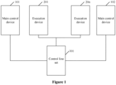
- a traction control simulation system for a rail vehicle includes: a control line set 301, two main control devices (101 and 102 as shown in Figure 1 ) and at least one execution device (201-20n as shown in Figure 1 ).
- the two main control devices and the execution device are all connected to the control line set.
- the two main control devices are configured to implement a traction control function and a traction monitoring function of a traction control device on the rail vehicle.
- a control line in the control line set is configured to implement a data transmission function of a train line on the rail vehicle.
- the execution device is configured to implement an operation execution function of a traction execution equipment on the rail vehicle.
- the two main control devices are configured to: transmit a vehicle control command to the execution device through the control line in the control line set, and to control the execution device to perform an operation corresponding to the vehicle control command.
- the two main control devices simulate a traction control device in a cab of a real rail vehicle. Only one main control device of the two main control devices is in a control state at the same time, for example, when the rail vehicle is moving from south to north, a first main control device is in a control state; and when the rail vehicle is traveling from north to south, a second main control device is in a control state.
- the number of execution devices may be configured according to the number of execution cars on the real rail vehicle, that is, the number of intermediate cars.
- a high-speed circuit breaker simulation unit and a traction converter simulation unit on the execution device are controlled through a control circuit and a driver controller on the main control device, thus the speed regulation and operation, and a traction safety interlock protection function of a traction motor are realized.
- FIG. 2 a specific structure of the two main control devices, the at least one execution device, and the control line set are shown.
- the number of execution devices is 3 as an example (see the execution devices 201-203 in Figure 2 ).
- the two main control devices each includes: a display simulation unit, a processor simulation unit, a driver controller traction control simulation circuit, a running direction and traction brake control simulation circuit, a high-speed circuit breaker control simulation circuit, a traction safety loop simulation circuit, an automatic train protection (ATP) zero-speed delay control simulation circuit, and a traction converter control simulation circuit.
- the display simulation unit, the driver controller traction control simulation circuit, the running direction and traction brake control simulation circuit, and the traction converter control simulation circuit are all connected to the processor simulation unit; the ATP zero-speed delay control simulation circuit is connected to the driver controller traction control simulation circuit; the traction safety loop simulation circuit, the high-speed circuit breaker control simulation circuit, the running direction and traction brake control simulation circuit, and the driver controller traction control simulation circuit are all connected to the control line set; and the traction converter control simulation circuit and the processor simulation unit are both connected to the execution device.
- the display simulation unit and the processor simulation unit are connected through a network cable, the driver controller traction control simulation circuit and the processor simulation unit are connected through a wire, and the running direction and traction brake control simulation circuit and the processor simulation unit are connected through a wire, and the traction converter control simulation circuit and the processor simulation unit are connected through a wire.
- the display simulation unit simulates a touch display on the real rail vehicle, which is used for displaying data to be displayed sent by the processor simulation unit, to realize human-computer interaction.
- the data to be displayed may be various types of commands received by the processor simulation unit, such as a driver controller traction command, a running direction control command, a traction brake command, a high-speed circuit breaker control command, a traction safety loop control command, a traction converter control command, or the like in the following.
- the driver controller traction control simulation circuit simulates a driver controller traction command output circuit on the real rail vehicle, and is configured to generate and output a driver controller traction command.
- the running direction and traction brake control simulation circuit simulates a running direction and traction brake command control circuit on the real rail vehicle, and is configured to generate and output a running direction control command and a traction brake command.
- the high-speed circuit breaker control simulation circuit simulates a high-speed circuit breaker control circuit on the real rail vehicle, and is configured to generate and output a high-speed circuit breaker control command.
- the traction safety loop simulation circuit simulates a traction safety loop circuit on the real rail vehicle, and is configured to generate and output a traction safety loop control command.
- the ATP zero-speed delay control simulation circuit simulates an ATP zero-speed delay control circuit, and is configured to establish a traction safety loop.
- the ATP zero-speed delay control simulation circuit is a power-off delay time relay. When a simulated train speed is lower than 5KM/H, it is energized, that is, the train is considered to be stationary. Since a normally-open contact thereof is connected in parallel with normally-open contacts of all brake relief relays and emergency brake loop relays, that is, when the vehicle is stationary and starts to run within 5 seconds, once the ATP zero-speed delay is powered off, a traction safety loop can be established even if the brake is relief.
- the traction converter control simulation circuit simulates a circuit for controlling a traction converter reset command, a standby mode command, and a car wash mode command on the real rail vehicle. And the traction converter control simulation circuit is configured to generate and output a traction converter control command.
- the traction converter control simulation circuit and the circuit for controlling a traction converter reset command, a standby mode command, and a car wash mode command are both control circuits that can manually control a traction converter to enter a special mode.
- a traction converter reset command button can be used to reset the traction converter unit.
- a standby mode command switch is switched to a standby mode position, the traction converter simulation unit enters a standby mode.
- the maximum speed is limited to 40 kilometers per hour, thus the traction converter simulation unit only receives a traction command at the 50% and 100% positions of a driver controller handle.
- a car wash mode command switch When a car wash mode command switch is switched to a car wash position, the traction converter unit enters a car wash mode.
- the traction converter simulation unit controls the traction motor to run at a speed of 3km/h.
- the processor simulation unit simulates a central processing unit on the real rail vehicle, and is configured to: receive commands from the driver controller traction control simulation circuit, the running direction and traction brake control simulation circuit, and the traction converter control simulation circuit, and output the commands to the display simulation unit to display.
- the traction safety loop simulation circuit the normally-open contact of the driver's cab activation relay in the control state, the normally-closed contact of the door selecting switch, the normally-open contact of the ATP cutting relay, the normally-open contact of the left door being closed relay, the normally-open contact of the right door being closed relay, the normally-open contact of the brake relief relay, the normally-open contact of the emergency brake relief relay, and the normally-open contact of the parking brake relief relay are connected in series, and then is connected to the traction safety control line in the control line set.
- the traction safety control line is connected to the normally-closed contact of the driver's cab activation relay in the non-control state, to form a closed traction safety monitoring loop.
- the normally-open contact of the door being closed bypass switch is connected in parallel with a circuit in which the normally-open contact of the left door being closed relay and the normally-open contact of the right door being closed relay are connected in series.
- the normally-open contact of the ATP zero-speed relay is connected in parallel with a circuit in which the normally-open contact of the brake relief relay and the normally-open contact of the emergency brake relief relay are connected in series.
- a traction safety loop includes contacts of the two main control devices and some relays of the execution unit. The loop connects all points that may affect train traction safety in series.
- Conditions for establishing the traction safety loop are: a driver's cab of the main control device 101 or the main control device 102 has been activated, a door selecting switch at the end of the activated driver's cab is at the "0" position, an ATP system has been cut off, left doors were all closed, right doors were all closed, all brakes have been relieved, an emergency braking loop has been established, all parking brakes have been relieved, and the tail car has been assembled through the control line.
- the traction safety loop is established through the activation relay in the driver's cab at the inactive end, and the control line corresponding to the traction safety loop is energized.
- An external interface circuit of the traction converter unit receives an command to establish the traction safety loop through the control line.
- the number of the execution device is three, and each execution device includes: a high-speed circuit breaker simulation unit, a traction converter simulation unit and a traction motor execution simulation unit. Further, the excitation device may also include a pantograph, which is configured to provide high-voltage power to the high-speed circuit breaker simulation unit.
- the high-speed circuit breaker simulation unit and the processor simulation unit are respectively connected to the traction converter simulation unit.
- the traction converter control simulation circuit is respectively connected to the traction converter simulation unit and the traction motor execution simulation unit.
- the high-speed circuit breaker simulation unit and the traction converter simulation unit are respectively connected to the control line set.
- the high-speed circuit breaker simulation unit obtains electric energy from the pantograph connected to the high-speed circuit breaker simulation unit.
- the traction converter simulation unit includes: a traction converter unit internal circuit and a traction converter unit external interface circuit.
- the traction converter unit internal circuit includes: a logic controller, a frequency converter, a forward command input relay -K23, a backward command input relay -K24, a brake command input relay -K25, a traction command input relay -K26, a traction safety command input relay -K27, a reset command input relay -K28, a standby mode command input relay -K29, a contact net position command input relay -K30, a first working power input relay -K31, a second working power input relay -K32, a high-speed circuit breaker sub-command input relay -K22, a brake status loop command input relay, -K20 and -K21, a high-speed circuit breaker status feedback command input relay -K19, an output relay -Q0.0 for outputting a K-line contactor (KIC) high voltage output command, an output relay -Q0.1 for outputting a command to allow a high-speed circuit breaker to close, an output
- the logic controller includes a CPU module and an I/O module, the I/O module is connected to the frequency converter, the CPU module is configured to generate a frequency converter control signal (such as control signals for forward rotation, reverse rotation, stop, start, and electric brake), and the I/O module is configured to transmit the frequency converter control signal to the frequency converter.
- a frequency converter control signal such as control signals for forward rotation, reverse rotation, stop, start, and electric brake
- the forward command input relay, the backward command input relay, the brake command input relay, the traction command input relay, the traction safety command input relay, the reset command input relay, the standby mode command input relay, the contact net position command input relay, the first working power input relay, the second working power input relay, the high-speed circuit breaker sub-command input relay, the brake status loop command input relay, and the high-speed circuit breaker status feedback command input relay are all connected to an input port of the logic controller.
- the output relay for outputting a KIC high voltage output command, the output relay for outputting a command to allow a high-speed circuit breaker to close, the output relay for outputting a high-speed circuit breaker closing command, the output relay for outputting a high-speed circuit breaker keep-on command, the output relay for outputting a brake status command, the output relay for outputting a standby brake status command, the output relay for outputting a traction status command, and the traction main circuit power supply contactor are all connected to an output port of the logic controller.
- Conditions for a traction converter to output a traction force are as follows: a high-voltage signal is valid, a high-speed circuit breaker is closed, a running direction signal is valid, a driver controller is in a traction position, a traction force command is established, a traction safety loop is established, and all brakes are relieved. Only all of the above conditions are satisfied, the traction converter will output traction and control the rotation of the traction motor.
- the status of the traction converter simulation unit and the status of the high-speed circuit breaker simulation unit are transmitted to a central processing unit through the network, and displayed on a touch display.
- a traction safety command, traction current, a traction force, a traction motor speed, a KIC status, a K-charging contactor (KCCC) status, a traction control unit status, a circuit breaker status of the high-speed circuit breaker unit, and a high-voltage effective signal are displayed.
- the logic controller includes a programmable controller as a control core for signal reception and transmission, and a network interface is reserved.
- a direction backward signal input interface “CF1-6” is connected to a backward command input relay, and a backward command is transmitted to a logic controller input port "10.5".
- a direction forward signal input interface “CF1-46” is connected to a forward command input relay, and a forward command is transmitted to a logic controller input port "10.4".
- a traction safety signal input interface "CF1-42" is connected to a traction safety command input relay, and a traction safety command is transmitted to a logic controller input port "11.0".
- a brake command signal input interface “CF1-53” is connected to a brake command input relay, and a brake command is transmitted to a logic controller input port "10.6".
- a traction command signal input interface “CF1-40” is connected to a traction command input relay, and a traction command is transmitted to a logic controller input port "I0.7”.
- a reset signal input interface “CF1-66” is connected to a reset command input relay, and a reset command is transmitted to a logic controller input port "I1.1”.
- a standby mode signal input interface “CF1-67” is connected to a standby mode command input relay, and a standby mode command is transmitted to a logic controller input port "I1.2”.
- a signal of a mode switch being in the state of the contact net input interface "CF1-18” is connected to a contact net position command input relay, and a state command of the contact net position is transmitted to a logic controller input port "I1.3".
- Interfaces "CF1-13" and “CF1-14” simulate a positive pole 110V of the working power supply of the traction device, which is connected to a first working power input relay and a second working power input relay. After contacts of the two power input relays are connected in series, a valid signal of the first working power supply and a valid signal of the second working power supply are transmitted to a COM port "L1" of the logic controller.
- An interface “CF1-37” simulates a negative pole 0V of the working power supply of the traction device, and is connected to ports "1L/2L" of a common terminal of the logic controller input module.
- a high-speed circuit breaker sub-signal input interface "CF1-30” is connected to a high-speed circuit breaker sub-command input relay, and a high-speed circuit breaker sub-command is transmitted to a logic controller input port "I0.3".
- Brake state loop signal input interfaces "CF1-64" and “CF1-65" are connected to two brake state loop command input relays, and status of the brake loop is transmitted to a logic controller input ports "10.1” and "I0.2”.
- Traction analog input interfaces "CF2-23" and “CF2-40” are connected to ports “A+” and "M” of the logic controller, to receive traction signals.
- CF1-04 is a feedback command interface for simulating the status of the high-speed circuit breaker received by the traction converter simulation unit, and it is connected to a feedback command input relay of the status of the high-speed circuit breaker, and is configured to transmit a feedback command of the status of the high-speed circuit breaker to a logic controller input port "10.0".
- Interface "CF1-3” simulates an interface for sending a high-speed circuit breaker closed output command by the traction converter simulation unit.
- Interface "CF1-15” simulates an interface for sending a KIC high-voltage output command by the traction converter simulation unit.
- the traction converter simulation unit outputs "1" if it detects that the high voltage is normal.
- Interface "CF1-27” simulates an interface for sending an output command that allows the high-speed circuit breaker to be closed by the traction converter simulation unit.
- Interface “CF1-28” simulates an interface of the traction converter simulation unit, which is used for providing a control power 110V for the high-speed circuit breaker.
- Interface "CF1-16” simulates an interface of the traction converter simulation unit, which is used for providing a control power 0V for the high-speed circuit breaker.
- "CF1-29” is a keep-on command for the high-speed circuit breaker provided by the traction converter simulation unit.
- "CF1-11” and “CF1-12” are output traction status commands, which are used for monitoring the running status of the traction converter simulation unit.
- "CF1-47” and “CF1-48” are output standby braking status commands, which are used for determining whether the traction converter simulation unit detects the standby braking status.
- "CF1-59” and “CF1-60” are output braking state commands, which are used for determining whether the traction converter simulation unit detects the braking state.
- CPMV1-1", CPMV1-2”, and “CPMV1-3” simulate the three-phase 380V load power supply of the traction converter simulation circuit, which is used for loads such as cooling fans and inverters, and are connected to the U, V, and W ports on the inverter.
- R","S", and “T” simulate traction motor terminals of the traction converter.
- the connection ports 3 and 4 on the inverter are connected to interfaces M and I of the logic controller, and are configured for transmitting analog speed control signals.
- the connection port 5 on the inverter is connected to an interface "Q1.0" of an output module of the logic controller, which is the forward rotation command of the inverter.
- connection port 6 on the inverter is connected to an interface "Q1.1" of the output module of the logic controller, which is the reverse rotation command of the inverter.
- the connection port 7 on the inverter is connected to an interface "Q1.2” of the output module of the logic controller, which is the reset command of the inverter.
- the connection port 8 on the inverter is connected to an interface "Q1.3" of the output module of the logic controller, which is the speed 1 command of the inverter.
- connection port 16 on the inverter is connected to an interface "Q1.4" of the output module of the logic controller, which is the speed 2 command of the inverter.
- connection port 17 on the inverter is connected to an interface "Q1.5" of the output module of the logic controller, which is the speed 3 command of the inverter.
- the connection port 9 on the inverter is connected to an interface "1L” of the output module of the logic controller, which is the common terminal connection of the inverter control command.
- the connection ports 19 and 20 on the frequency converter are the frequency converter status output ports, which are reserved as spare ports in the present disclosure.
- “Q1.6” and “Q1.7" are digital output interfaces of the output module of the logic controller, which are reserved as spare interfaces in the present disclosure.
- A1 and B1 are speed signal interfaces, which are used for receiving the speed of the traction motor and performing speed closed-loop control.
- the logic controller detects the following conditions: a high-speed circuit breaker status feedback command input relay feeding back a high-voltage signal valid command and a high-speed circuit breaker closing command, the forward command input relay and the backward command input relay feeding back an operation direction signal valid command, and the traction command input relay feeding back that the driver controller is in the traction position, the traction safety loop being established, and the driver controller handle outputting the traction angle signal. Only the above conditions are all satisfied, the traction converter will output the traction force and control the rotation of the traction motor.
- the status of the traction converter simulation unit and the status of the high-speed circuit breaker simulation unit are transmitted to the processor simulation unit through the network, and displayed on the man-machine interface.
- the traction safety command, the traction current, the traction force, the traction of the traction converter motor speed, the KIC high voltage status, the traction control unit status, the circuit breaker status of high-speed circuit breaker unit, and the high voltage effective signals are displayed.
- the driver controller of the main control device includes a traction zone, an idle travel position and a braking zone, where P zone is the traction zone, COAST zone is the idle travel position, and B zone is the braking zone.
- the traction section is divided into four levels P1, P2, P3, and P4, starting from the idle travel position, traction force in each level increases by 25%.
- a rotation angle of a driver control handle is reflected by the change of gray codes of an encoder.
- a current signal of 4-20mA is output to the outside.
- the braking zone is divided into six levels B1, B2, B3, B4, B5 and EB.
- a traction command is output to a traction control line through a driver controller traction control simulation circuit.
- the traction converter unit of the execution device receives the traction command on the traction control line through the external interface circuit, and controls the traction converter unit to control the magnitude of the traction force of the traction motor according to the traction command.
- the driver controller advances to the traction position, and the farther away it is from the idle travel position, the greater the traction force is, and vice versa.
- Figure 6b shows traction control lines.
- Three traction converter simulation units transmit a current signal of 4-20mA corresponding to the change of the angle of the driver controller handle through the train line to signal ports "CF2-40" and "CF2-23".
- the simulated traction unit uses this value to determine the frequency of the output pulse width modulation (PWM).
- PWM pulse width modulation
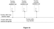
- Figure 6c shows traction safety control lines.
- the traction safety loop train line is a through line established by the loop.
- the output of the traction safety loop train line is positive 110V
- "CF1-42" is a traction enabled signal input terminal, and this terminal is positive 110V when the full train traction safety loop is established.
- Figure 7a is a schematic structural diagram of a running direction and traction brake control simulation circuit.
- a direction handle is in an F position
- a forward signal line is high
- a running direction control circuit in the running direction and traction brake control simulation circuit outputs a running direction signal of the traction motor through the running direction switch.
- the running direction signal is divided into: forward (F), 0 position, and backward (R).
- F forward
- R backward
- the switch is turned to "forward”
- the running direction and the running direction train line in the high-speed circuit breaker control line's traction forward signal line is at a high level.
- the switch is turned to "backward”
- the traction backward signal line of the train line in the running direction is at a high level.
- the switch is set to the "0" position, the traction of the train line in the running direction forwards and the backward signal line is at a low level.
- a traction brake command control circuit in the running direction and traction brake control simulation circuit outputs a signal by the driver controller.
- the driver controller When the driver controller is pushed to the traction position, the traction command signal line and the brake command signal line in the traction and brake control lines are both at a high level.
- the driver controller When the driver controller is pushed to the braking position, the traction command signal line and the brake command signal line in the traction and brake control lines are both at a low level.
- the running direction command is at a high level on the forward signal line or the backward signal line, the running direction signal is valid.
- the driver controller is in the traction position.
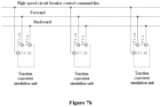
- Figure 7b shows the running direction and high-speed circuit breaker control line.
- the three traction converter simulation units introduce the direction signal into the traction transformer through the forward signal, the backward signal train line and their respective signal input interfaces "CF1-46" and "CF1-6".
- the simulated traction unit determines the rotation direction of the traction motor based on this signal.
- the high-speed circuit breaker control command line transmits the high-speed circuit breaker closing/breaking signal.
- "CF1-30" is positive 110V
- the traction converter simulation unit controls the high-speed circuit breaker to close
- the traction converter simulation unit controls the high-speed circuit breaker to open.
- Figure 7c shows the traction and braking control line.
- the three traction converter simulation units determines whether to output the traction power through the traction command, brake command train line and their respective signal input terminals "CF1-53" and "CF1-40".
- Figure 8 shows the high-speed circuit breaker control circuit.
- the high-speed circuit breaker control command line transmits the signal through the train line to the car connector. At the same time, the signal is sent to the vehicle information system.
- the high-speed circuit breaker control circuit is a control circuit that controls the opening of the high-speed circuit breaker of the execution device through the train line.
- the high-speed circuit breaker unit can control the traction converter simulation unit to receive the high-voltage electrical signal connected by the pantograph.
- Figure 9 shows an ATP zero-speed delay control simulation circuit, illustrating a power-off delay time relay.
- a simulated train speed is lower than 5KM/H, it is energized, that is, the train is considered to be stationary. Since a normally-open contact thereof is connected in parallel with normally-open contacts of all brake relief relays and emergency brake loop relays, that is, when the vehicle is stationary and starts to run within 5 seconds, once the ATP zero-speed delay is powered off, a traction enable signal can be output even if the brake is relief.
- Figure 10 shows an external interface circuit of the traction converter unit.
- the interface described in the figure is designed in the form of a connector, such that the traction converter simulation unit can be connected to the system conveniently and quickly.
- "CF1-6” is a backward direction signal input interface.
- CF1-46 is a forward direction signal input interface.
- CF1-42 is a traction safety signal input interface.
- CF1-53 is an input interface of a brake command signal.
- “CF1-40” is a traction command signal input interface.
- “CF1-66” is a reset signal input interface.
- “CF1-67” is a standby mode signal input interface.
- “CF1-18” is a signal input interface when a mode switch is in the contact network.
- CF1-13” and “CF1-14” are the positive pole 110V of the working power supply of the simulated traction device.
- CF1-37 is the negative pole 0V of the working power supply of the simulated traction device.
- CF1-30 is a high-speed circuit breaker sub-signal input interface.
- CF1-64" and “CF1-65" are input interfaces of the brake state loop signal.
- CF2-23" and “CF2-40” are traction simulation input interfaces.
- CF1-4” is a feedback command interface of the received high-speed circuit breaker status.
- CF1-3 is an output command interface issued to the closing of the high-speed circuit breaker.
- CF1-15 is an interface for issuing a high-voltage output command to the high-speed circuit breaker KIC.
- CF1-27 is an output command interface sent to the simulated high-speed circuit breaker to allow closing.
- CF1-28 is a positive power supply of 110V for high-speed circuit breaker control.
- CF1-16 is power supply of 0V for high-speed circuit breaker control.
- CF1-29 is a keep-on command for the high-speed circuit breaker.
- CF1-11” and “CF1-12” are output traction status commands.
- CF1-47” and “CF1-48” are output standby braking status commands.
- CF1-59” and “CF1-60” are output braking status commands.
- CF1-24" and “CF1-36” are positive input ports of the standby power supply.
- R, “S”, and “T” are terminal of the traction motor of the simulated traction converter.
- CPMV1-1", “CPMV1-2”, and “CPMV1-3” are three-phase 380V load power supplies for the traction converter simulation unit.
- Figure 11 shows a high-speed circuit breaker simulation unit.
- the high-speed circuit breaker simulation unit includes an internal circuit and an external interface circuit of the high-speed circuit breaker unit. It describes the simulation method of the high-speed circuit breaker of the traction system.
- "X-HSCB1-1" to "X-HSCB1-8" are interfaces of the traction converter simulation unit, port 6a is a simulated positive electricity input port for a high-voltage valid signal, port 2 is a simulated positive electricity output port for the high-voltage valid signal, port 6b is a simulated negative electricity input port for the high-voltage valid signal, and ports 12a to 12d are simulated negative electricity output ports for the high-voltage valid signal.
- Functions of the above ports are respectively: a closing high-speed circuit breaker signal, a KIC high voltage signal, a closed status signal fed back by the high-speed circuit breaker to the traction converter simulation unit, a closing permission signal, a positive hold signal for a power supplied by the traction converter simulation unit to the high-speed circuit breaker, and a negative hold signal for the power supplied by the traction converter simulation unit to the high-speed circuit breaker.
- the high-speed circuit breaker simulation unit includes: a close high-break signal input relay "-K1”, a KIC high-voltage signal input relay “-K2”, a close permission signal input relay “-K3”, a hold signal input relay "-K4", a high-speed circuit breaker close contactor "-K0”, a high-speed circuit breaker close enable relay "-K6”, and a protection delay relay "-KT0".
- the close high-speed circuit breaker signal input relay is connected to an external interface of a closed high-speed circuit breaker, and is configured to receive a signal to close the high-speed circuit breaker.
- the KIC high-voltage signal input relay is connected to a KIC high-voltage external interface, and is configured to receive a KIC high-voltage valid signal.
- the close permission signal input relay is connected to a close permission external interface for receiving a close permission signal of the high-speed circuit breaker.
- the hold signal input relay is connected to a hold signal external interface and is configured to receive a hold signal of the high-speed circuit breaker.
- the high-speed circuit breaker close enable relay is connected to a normally-open contact of the close permission signal input relay, and a normally-open contact of the close permission signal input relay is connected to a normally-open contact of the close high-speed circuit breaker signal input relay, thus the high-speed circuit breaker close enable relay is controlled by connecting the two contacts in series.
- the protection delay relay is connected to a normally-closed contact of the KIC high-voltage signal input relay, and the normally-closed contact of the KIC high-voltage signal input relay is connected to a normally-open contact of a high-speed circuit breaker closing contactor, thus the protection delay relay is controlled by connecting the two contacts in series.
- the high-speed circuit breaker closing contactor is connected to a normally-closed contact of the protection delay relay, and the normally-closed contact of the protection delay relay is connected to a normally-open contact of the close permission signal input relay, thus the normally-open contact of the signal input relay is connected in parallel with the normally-open contact of the high-speed circuit breaker close enable relay, and is connected with the normally-open contact of the close permission signal input relay.
- the high-speed circuit breaker is controlled by connecting the four contacts in series and parallel.
- the closing of the high-speed circuit breaker is realized by exchanging a control command through the external interface circuit of the high-speed circuit breaker unit and the external interface circuit of the traction converter unit.
- the internal circuit of the high-speed circuit breaker simulation unit transmits a valid high-voltage signal of the pantograph and a normal signal of the high-speed circuit breaker to the traction converter simulation unit.
- the traction converter simulation unit performs the equipment self-check, to determine whether the following conditions are satisfied: traction self-check being normal, the traction command being valid, the running direction command being valid, the high-voltage electricity being valid, and the high-speed circuit breaker simulation unit being normal.
- the traction converter simulation unit outputs a high-speed circuit breaker close command to the high-speed circuit breaker simulation unit, and the high-speed circuit breaker is closed.
- the traction converter simulation unit receives a high-voltage electrical signal, and issues a high-speed circuit breaker closing hold command, and the high-speed circuit breaker remains closed.
- the high-speed circuit breaker is disconnected:
- a pantograph of a switchboard in each execution device is connected to a high-speed circuit breaker simulation unit of the switchboard (the high-speed circuit breaker simulation unit includes an internal circuit of the high-speed circuit breaker unit and an external interface circuit).
- the high-speed circuit breaker simulation unit of each switchboard is connected to an external interface circuit of a traction converter unit of the switchboard.
- An internal circuit of the traction converter unit of each switchboard is connected to an external interface circuit of the traction converter unit of the switchboard.
- the external interface circuit of the traction converter unit of each switchboard is connected to a traction motor actuator of the switchboard.
- Two processor simulation units and internal circuits of traction converter units of three switchboards are connected by network cables, and the ATP zero-speed delay control circuit is connected to the driver controller traction control simulation circuit.
- the high-speed circuit breaker control simulation circuit disconnects a control circuit of a high-speed circuit breaker main contactor of the high-speed circuit breaker simulation unit of the execution device through a control line in the control line set.
- the high-speed circuit breaker simulation unit can control the traction converter simulation unit to receive the high-voltage electrical signal connected by the pantograph.
- the closing of the main contactor of the high-speed circuit breaker is realized by exchanging a control command through the external interface circuit of the high-speed circuit breaker unit and the external interface circuit of the traction converter unit.
- the internal circuit of the high-speed circuit breaker simulation unit transmits a valid high-voltage signal of the pantograph and a normal signal of the high-speed circuit breaker to the traction converter simulation unit.
- the traction converter simulation unit After the traction converter simulation unit performs the equipment self-check, to determine whether the following conditions are satisfied: traction self-check being normal, the traction command being valid, the running direction command being valid, the high-voltage electricity being valid, and the high-speed circuit breaker simulation unit being normal. If all the above conditions are satisfied, the traction converter simulation unit outputs a high-speed circuit breaker close command to the high-speed circuit breaker simulation unit, and the high-speed circuit breaker is closed. After the high-speed circuit breaker is closed, the traction converter simulation unit receives a high-voltage electrical signal, and issues a high-speed circuit breaker closing hold command, and the high-speed circuit breaker remains closed. When the following situations occur, the high-speed circuit breaker is disconnected:
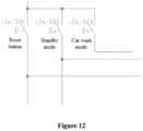
- Figure 12 shows a traction converter control simulation circuit.
- a standby mode switch " 24-S02”, and when it is closed, the traction converter simulation unit enters a standby mode, with the maximum speed to 40 kilometers per hour.
- the traction converter simulation unit only receives two signals of 50% and 100% of the handle.
- the train line includes: a traction safety control line, a traction control line, a traction and brake control line, a running direction and high-speed circuit breaker control line.
- the traction safety control line is connected to the traction safety loop simulation circuit; the traction control line is connected to the driver controller traction control simulation circuit; the traction and brake control line is connected to the running direction and traction and brake control simulation circuit; the running direction and high-speed circuit breaker control line is respectively connected to the running direction and traction and brake control simulation circuit and the high-speed circuit breaker control simulation circuit.
- the traction control line is respectively connected to external interface circuits of traction converter units of three switchboards.
- the traction and brake control line is respectively connected to external interface circuits of traction converter units of three switchboards.
- the running direction and high-speed circuit breaker control line is respectively connected to external interface circuits of traction converter units of three switchboards, and the running direction and high-speed circuit breaker control line is also respectively connected to internal circuits and external interface circuits of high-speed circuit breaker units of three switchboards.
- the traction safety control line is respectively connected to external interface circuits of traction converter units of three switchboards.
- Two processor simulation units and internal circuits of traction converter units of three switchboards are connected by network cables, and a control status of a logic control PLC of the internal circuit of the traction converter unit and a monitoring status are transmitted to the processor simulation unit through the network cables, and are displayed on a display simulation unit.
- the ATP zero-speed delay control circuit is connected to the traction control simulation circuit of the driver controller.
- the ATP zero-speed delay control circuit is used as a condition for the establishment of the traction control simulation circuit of the driver controller.
- Two driver controller traction control simulation circuits are connected to the traction control line to establish a complete output circuit of the traction command.
- the traction control line is respectively connected to external interface circuits of traction converter units of three switchboards, thus the traction commands are sent to the external interface circuits of the three traction converter units respectively.
- Two running direction and traction brake control simulation circuits are connected to the traction and brake control line, thus a complete output circuit for traction commands and brake commands is established.
- the traction and brake control line is respectively connected to external interface circuits of traction converter units of three switchboards, thus the traction commands and brake commands are respectively sent to the external interface circuits of the three traction converter units.
- the two running direction and traction brake control simulation circuits are connected to the running direction and the high-speed circuit breaker control line, thus a complete output circuit for the running direction is established.
- the two high-speed circuit breaker control simulation circuits are connected to the running direction and the high-speed circuit breaker control line, thus a control circuit for high-speed circuit breaker control commands is established.
- the running direction and high-speed circuit breaker control line is respectively connected to external interface circuits of traction converter units of three switchboards, thus running direction commands are respectively sent to the external interface circuits of the three traction converter units.
- the running direction and high-speed circuit breaker control line is also respectively connected to internal circuits and external interface circuits of high-speed circuit breaker units of three switchboards, thus high-speed circuit breaker control commands are respectively sent to the internal circuits and external interface circuits of the three high-speed circuit breaker simulation units.
- Two traction safety loop simulation circuits are connected to the traction safety loop simulation circuit and the traction safety command train line in the traction safety control line, to establish a complete traction safety loop circuit.
- the traction safety control line is respectively connected to external interface circuits of traction converter units of three switchboards, thus commands for establishing the traction safety loop are respectively sent to the external interface circuits of the three traction converter units.
- a pantograph of a switchboard in each execution device is connected to an internal circuit and an external interface circuit of the high-speed circuit breaker unit, thus a high-voltage valid signal and a high-voltage invalid signal of the pantograph are transmitted to the internal circuit and the external interface circuit of the high-speed circuit breaker simulation unit.
- the high-speed circuit breaker simulation unit of each switchboard is connected to an external interface circuit of a traction converter unit of the switchboard, thus the external interface circuit of the traction converter unit can monitor the status of an internal function of the high-speed circuit breaker and control the high-speed circuit breaker to realize functions thereof.
- An internal circuit of the traction converter unit of each switchboard is connected to an external interface circuit of the traction converter unit of the switchboard, thus the external interface circuit of the traction converter unit can transmit an external control command and monitored information to the internal circuit of the traction converter unit, and the internal circuit of the traction converter unit can send its own control state and logic control command to the external interface circuit of the traction converter unit.
- the external interface circuit of the traction converter unit of each switchboard is connected to a traction motor actuator of the switchboard, thus the external interface circuit of the traction converter unit can drive a traction motor of a traction motor execution simulation unit to run, and monitor a speed sensor of the traction motor execution simulation unit to performs speed closed-loop control.
- a logic controller of the traction control simulation system performs logic control according to the following procedure.
- self-check is performed by the main program first to check whether the program is normal and whether the basic hardware is faulty. After the self-check, it is determined whether a high speed circuit breaker (HSCB) high-voltage signal is valid or not, the HSCB is re-detected if it the high-voltage signal is invalid, and the HSCB is closed if the high-voltage signal is valid.
- HSCB high speed circuit breaker
- the traction control simulation system After closing the HSCB, it is determined whether the traction control simulation system receives a valid high-voltage signal; and the HSCB is disconnected and self-check of the main traction program is performed again if the valid high-voltage signal is not received. If the valid high-voltage signal is received, a pre-charge contactor of the traction main circuit is closed, and whether the intermediate voltage is established is checked. A main contactor is closed if the intermediate voltage is established. After the main contactor is closed, traction conditions are determined. The traction loop needs to be established, the traction enable is established, and the running direction command is valid, then a traction mode is entered. In the traction mode, the traction control simulation system selects an operating condition according to a position command of the driver controller.
- the traction force is output according to a traction command ratio of a driver control handle; if the driver controller is in an idle travel position, the traction force is not output; if the driver controller is in a braking position, and it is judged according to a vehicle speed. When the vehicle speed is less than 8km/h, no electric braking force is output. When the vehicle speed is greater than 8km/h, the electric braking force is output according to the position of the driver controller.
- the traction control simulation system for a rail vehicle includes a control line set, two main control devices and at least one execution device, which conforms to the layout of a traction control device of a master vehicle and a traction execution equipment of an executive vehicle in the rail vehicle.
- the two main control device transmit a vehicle control command to an execution device through a control line in the control line set, to control the execution device to execute an operation corresponding to the vehicle control command, which conforms to the way of controlling the traction execution equipment of the executive vehicle by the traction control device of the master vehicle in the rail vehicle.
- the difference between the traction control simulation system of the present disclosure and a traction control system of an real rail vehicle is small, that is, a simulation degree of the traction control simulation system of the present disclosure is relatively high, and thus the traction control simulation system of the present disclosure can be used to replace the traction control system of the real rail vehicle during debugging and training. Since the traction control simulation system of the present disclosure exists independently, the operation safety is higher, and the running stability and the safety of the real rail vehicle are not affected. In addition, the traction control system of the real rail vehicle is not used for training, and the traction control simulation system of the present disclosure can be used for multiple trainings, thereby saving costs.
- the traction control simulation system provided in this embodiment is used to simulate urban subways and light rail vehicles. All components are made of non-loading originals, and the cost is extremely low, which solves domestic technical problems.
- the traction control simulation system has advantages of strong pertinence, high degree of simulation, low cost, and low operating cost. Each module thereof has complete functions, which can be implemented individually or connected to another vehicle control and monitoring system (TCMS), to achieve networked information, thereby embodying the technical content of urban rail vehicles and the unique technology and skill characteristics of vehicle assembly and dispatching.
- TCMS vehicle control and monitoring system
- back-end support and front-end functional hardware are organically integrated through logical connection and network connection of the above-mentioned hardware.
- the arrangement of the execution device and the two main control devices conforms to the layout of the main control vehicle and the execution vehicle of the urban railway vehicle.
- the arrangement of the three identical traction system components of the executive device reflects the centralized and unified control of the traction system of the urban railway vehicle and the independent control of the single vehicle. That is, the main control vehicle controls traction function signal commands of the whole train, the single vehicle receives the main control command, and the single vehicle controls the traction actuator of the single vehicle to realize the traction function.
- the main functions of the traction control system of the urban railway vehicle are embodied. Unique debugging skills of the urban railway vehicle are also embodied.
- the degree of simulation is high.
- the interfaces and wiring logic of all components are arranged in accordance with a real urban railway vehicle.
- the trainer can write the debugging method of the training device according to the debugging content of the urban railway vehicle, so that the trainees can carry out standardized operations according to the debugging method, thus the training efficiency is high and the cost is low.
- the training by using small and compact three units to simulate the traction system function of the urban railway vehicle has following advantages.
- the walking range is small due to centralized parts, which saves personnel walking time, and the impact of the function and performance of training on real vehicles is reduced. Unexpected quality problems are avoided and losses are reduced.
- the trainee can understand the vehicle structure and working principle, and quickly learn vehicle data.
- a traction control method is provided in another embodiment of the present disclosure, which is applied to the two main control devices in a control state in the above-mentioned traction control simulation system, and the traction control method includes: sequentially receiving multiple control commands input by an user in chronological order and outputting each of the multiple control commands to each execution device through a corresponding control line in the control line set; determining, by each execution device, whether each of the multiple control commands is a valid control command in turn; and executing an operation corresponding to the valid control command in case of determining that each of the multiple control commands is the valid control command.
- the sequentially receiving multiple control commands input by an user in chronological order and outputting each of the multiple control commands to each execution device through a corresponding control line in the control line set includes:
- an execution process of the traction control method is as follows.
- a switchboard 1 of an execution device use a multi-meter to measure an upper port voltage of circuit breakers 25-F02, 25-F03, and 25-F04 respectively, and determine whether a lower port of the circuit breakers 25-F02, 25-F03, and 25-F04 is short-circuited to a load respectively.
- the upper port voltage is DC110V
- the lower port is not short-circuited to line 32100. Close the circuit breaker 25-F02 and confirm that there is a direct-current voltage DC110V between a port CF1-13 and ports CF1-37, 38, 49 on an interface terminal block of a traction converter.
- a switchboard 2 of the execution device use a multi-meter to measure an upper port voltage of circuit breakers 25-F02, 25-F03, and 25-F04 respectively, and determine whether a lower port of the circuit breakers 25-F02, 25-F03, and 25-F04 is short-circuited to a load respectively.
- the upper port voltage is DC110V
- the lower port is not short-circuited to line 32100. Close the circuit breaker 25-F02 and confirm that there is a direct-current voltage DC110V between a port CF1-13 and ports CF1-37, 38, 49 on an interface terminal block of a traction converter.
- a switchboard 3 of the execution device use a multi-meter to measure an upper port voltage of circuit breakers 25-F02, 25-F03, and 25-F04 respectively, and determine whether a lower port of the circuit breakers 25-F02, 25-F03, and 25-F04 is short-circuited to a load respectively.
- the upper port voltage is DC110V
- the lower port is not short-circuited to line 32100. Close the circuit breaker 25-F02 and confirm that there is a direct-current voltage DC110V between a port CF1-13 and ports CF1-37, 38, 49 on an interface terminal block of a traction converter.
- HMI human machine interface
- a traction safety command box is green on a HMI; confirm that there is direct-current voltage DC110V between a port CF1-42 and the port CF1-37 on the three interface terminal blocks of the traction converter of the execution device.
- EMU Electric Multiple Units
- a driver controller key of the main control device 101 activate a driver's cab, and confirm and check that head relays 21-K01, 21-K02, 21-K03, 21-K04, 21-K05, 21-K06, 21-K07, 21-K08, 21-K09, 21-K10, 21-K12, and 21-K11 are closed, and confirm that the driver's cab of the main control device 101 has been activated on the HMI.
- each step of a manual operation in this embodiment will generate a current control command, and a result of the current control command will be displayed on the display simulation unit. And the result displayed on the display simulation unit is used to determine whether the current control command is executed successfully. After the current control command is executed successfully, a next step is manually executed and the above process is repeated.
- the simulation device in the present disclosure may also be faulted by activating a fault setting relay, resulting in a lack of function, thereby enabling personnel to input a fault code through a clicker after analysis and measurement, and determining whether the answer is correct by comparing the fault code with the database, that is, the training of fault identification may also be realized by the simulation device in the present disclosure.
Landscapes
- Engineering & Computer Science (AREA)
- Theoretical Computer Science (AREA)
- Business, Economics & Management (AREA)
- Physics & Mathematics (AREA)
- Educational Administration (AREA)
- Educational Technology (AREA)
- General Physics & Mathematics (AREA)
- Aviation & Aerospace Engineering (AREA)
- Electric Propulsion And Braking For Vehicles (AREA)
- Train Traffic Observation, Control, And Security (AREA)
Claims (9)
- Traktionssteuersimulationssystem für ein Schienenfahrzeug, umfassend:
einen Steuerleitungssatz (301), zwei Hauptsteuervorrichtungen (101, 102) und zumindest eine Ausführungsvorrichtung (201-20n), wobei:die zwei Hauptsteuervorrichtungen (101, 102) und die Ausführungsvorrichtung (201-20n) mit dem Steuerleitungssatz (301) verbunden sind;die zwei Hauptsteuervorrichtungen (101, 102) dazu konfiguriert sind, eine Traktionssteuerfunktion und eine Traktionsüberwachungsfunktion einer Traktionssteuervorrichtung an dem Schienenfahrzeug umzusetzen, wobei sich jeweils nur eine Hauptsteuervorrichtung der zwei Hauptsteuervorrichtungen (101, 102) in einem Steuerzustand befindet;eine Steuerleitung in dem Steuerleitungssatz (301) dazu konfiguriert ist, eine Datenübertragungsfunktion einer Zugleitung auf dem Schienenfahrzeug zu implementieren;die Ausführungsvorrichtung (201-20n) dazu konfiguriert ist, eine Betriebsausführungsfunktion einer Traktionsausführungseinrichtung auf dem Schienenfahrzeug umzusetzen; unddie zwei Hauptsteuervorrichtungen (101, 102) ferner dazu konfiguriert sind: einen Fahrzeugsteuerbefehl über die Steuerleitung im Steuerleitungssatz (301) an die Ausführungsvorrichtung (201-20n) zu übertragen, und die Ausführungsvorrichtung (201-20n) dahingehend zu steuern, einen Vorgang auszuführen, der dem Fahrzeugsteuerbefehl entspricht. - Traktionssteuersimulationssystem nach Anspruch 1, wobei die zwei Hauptsteuervorrichtungen (101, 102) jeweils aufweisen: eine Anzeigesimulationseinheit, eine Prozessorsimulationseinheit, eine Traktionssteuersimulationsschaltung der Fahrersteuerung, eine für die Fahrtrichtungs- und Traktionsbremssteuersimulationsschaltung, eine Hochgeschwindigkeitsleistungsschaltersteuersimulationsschaltung, eine Traktionssicherheitsschleifensimulationsschaltung, eine Nullgeschwindigkeitsverzögerungssimulationsschaltung für den automatischen Zugschutz (automatic train protection, ATP) und eine Traktionskonvertersteuersimulationsschaltung;wobei die Anzeigesimulationseinheit, die Traktionssteuersimulationsschaltung der Fahrersteuerung, die Fahrtrichtungs- und Traktionsbremssteuersimulationsschaltung und die Traktionskonvertersteuersimulationsschaltung mit der Prozessorsimulationseinheit verbunden sind; die ATP-Nullgeschwindigkeitsverzögerungssimulationsschaltung mit der Traktionssteuersimulationsschaltung der Fahrersteuerung verbunden ist; die Traktionssicherheitsschleifensimulationsschaltung, die Hochgeschwindigkeitsleistungsschaltersteuersimulationsschaltung, die Fahrtrichtungs- und Traktionsbremssteuersimulationsschaltung der Fahrersteuerung und die Traktionssteuersimulationsschaltung der Fahrersteuerung mit dem Steuerleitungssatz (301) verbunden sind; und die Traktionskonvertersteuersimulationsschaltung und die Prozessorsimulationseinheit jeweils mit der Ausführungsvorrichtung (201-20n) verbunden sind;wobei die Anzeigesimulationseinheit dazu konfiguriert ist, von der Prozessorsimulationseinheit gesendete anzuzeigende Daten anzuzeigen;wobei die Traktionssteuersimulationsschaltung der Fahrersteuerung dazu konfiguriert ist, einen Traktionsbefehl der Fahrersteuerung zu erzeugen und auszugeben;wobei die Fahrtrichtungs- und Traktionsbremssteuersimulationsschaltung dazu konfiguriert ist, einen Laufrichtungssteuerungsbefehl und einen Traktionsbremsenbefehl zu erzeugen und auszugeben;wobei die Hochgeschwindigkeitsleistungsschaltersteuersimulationsschaltung dazu konfiguriert ist, einen Steuerbefehl für einen Hochgeschwindigkeitsleistungsschalter zu erzeugen und auszugeben;wobei die Traktionssicherheitsschleifensimulationsschaltung dazu konfiguriert ist, einen Traktionssicherheitsschleifensteuerbefehl zu erzeugen und auszugeben;wobei die ATP-Nullgeschwindigkeitsverzögerungssimulationsschaltung dazu konfiguriert ist, eine Traktionssicherheitsschleife einzurichten;wobei die Traktionskonvertersteuersimulationsschaltung dazu konfiguriert ist, einen Traktionskonvertersteuerbefehl zu erzeugen und auszugeben; undwobei die Prozessorsimulationseinheit dazu konfiguriert ist, Befehle von der Traktionssteuersimulationsschaltung der Fahrersteuerung, der Fahrtrichtungs- und Traktionsremssteuersimulationsschaltung und der Traktionskonvertersteuersimulationsschaltung zu empfangen und die Befehle zur Anzeige an die Anzeigesimulationseinheit auszugeben.
- Traktionssteuersimulationssystem nach Anspruch 1, wobei in der Traktionssicherheitsschleifensimulationsschaltung ein normalerweise offener Kontakt eines Fahrerkabinenaktivierungsrelais in einem Steuerzustand, ein normalerweise geschlossener Kontakt eines Türauswahlschalters, ein normalerweise offener Kontakt eines ATP-Unterbrechungsrelais, ein normalerweise offener Kontakt eines Relais für geschlossene linke Tür, ein normalerweise offener Kontakt eines Relais für geschlossene rechte Tür, ein normalerweise offener Kontakt eines Bremsentlastungsrelais, ein normalerweise offener Kontakt eines Notbremsentlastungsrelais und ein normalerweise offener Kontakt eines Feststellbremsentlastungsrelais in Reihe geschaltet und mit einer Traktionssicherheitssteuerleitung in dem Steuerleitungssatz (301) verbunden sind;wobei die Traktionssicherheitssteuerleitung im Nichtsteuerzustand mit einem normalerweise geschlossenen Kontakt des Fahrerkabinenaktivierungsrelais verbunden ist, um eine geschlossene Traktionssicherheitsüberwachungsschleife auszubilden;wobei ein normalerweise offener Kontakt eines Bypass-Schalters für geschlossene Türen parallel zu einem Schaltkreis geschaltet ist, der den normalerweise offenen Kontakt des Relais für geschlossene linke Tür und den normalerweise offenen Kontakt des Relais für geschlossene rechte Tür in Reihe umfasst; undwobei ein normalerweise offener Kontakt eines ATP-Nullgeschwindigkeitsrelais parallel zu einem Schaltkreis geschaltet ist, der den normalerweise offenen Kontakt des Bremsentlastungsrelais und den normalerweise offenen Kontakt des Notbremsentlastungsrelais in Reihe umfasst.
- Traktionssteuersimulationssystem nach Anspruch 2, wobei die Anzahl der Ausführungsvorrichtungen (201-20n) drei beträgt und jede Ausführungsvorrichtung (201-20n) umfasst: eine Hochgeschwindigkeitsleistungsschaltersimulationseinheit, eine Traktionskonvertersimulationseinheit und eine Traktionsmotorausführungssimulationseinheit;wobei die Hochgeschwindigkeitsleistungsschaltersimulationseinheit und die Prozessorsimulationseinheit jeweils mit der Traktionskonvertersimulationseinheit verbunden sind;wobei die Traktionskonvertersteuersimulationsschaltung mit der Traktionskonvertersimulationseinheit bzw. der Traktionsmotorausführungssimulationseinheit verbunden ist;wobei die Hochgeschwindigkeitsleistungsschaltersimulationseinheit und die Traktionskonvertersimulationseinheit jeweils mit dem Steuerleitungssatz (301) verbunden sind; undwobei die Hochgeschwindigkeitsleistungsschaltersimulationseinheit elektrische Energie von einem mit der Hochgeschwindigkeitsleistungsschaltersimulationseinheit verbundenen Stromabnehmer bezieht.
- Traktionssteuersimulationssystem nach Anspruch 4, wobei die Traktionskonvertersimulationseinheit umfasst: einen internen Schaltkreis der Traktionskonvertereinheit und einen externen Schnittstellenschaltkreis der Traktionskonvertereinheit;wobei der interne Schaltkreis der Traktionskonvertereinheit umfasst: eine Logiksteuerung, einen Frequenzkonverter, ein Vorwärtsbefehleingangsrelais, ein Rückwärtsbefehleingangsrelais, ein Bremsbefehleingangsrelais, ein Traktionsbefehleingangsrelais, ein Traktionssicherheitsbefehleingangsrelais, ein Reset-Befehleingangsrelais, ein Standbymodus-Befehlseingangsrelais, ein Kontaktnetzpositionsbefehleingangsrelais, ein erstes Arbeitsleistungseingangsrelais, ein zweites Arbeitsleistungseingangsrelais, ein Hochgeschwindigkeitsleistungsschalterunterbefehlseingangsrelais, ein Bremsstatusschleifenbefehlseingangsrelais, ein Hochgeschwindigkeitsleistungsschalterstatusrückmeldungsbefehlseingangsrelais, ein Ausgaberelais zum Ausgeben eines K-Leitungsschütz(KIC)-Hochspannungsausgangsbefehl, ein Ausgaberelais zum Ausgeben eines Befehls, um das Schließen eines Hochgeschwindigkeitsleistungsschalters zu ermöglichen, ein Ausgaberelais zum Ausgeben eines Hochgeschwindigkeitsleistungsschalterschließbefehls, ein Ausgaberelais zum Ausgeben eines Hochgeschwindigkeitsschalterhaltebefehls, ein Ausgaberelais zum Ausgeben eines Bremsstatusbefehls, ein Ausgaberelais zum Ausgeben eines Standby-Bremsstatusbefehls, ein Ausgaberelais zum Ausgeben eines Traktionsstatusbefehls und einen Schütz zur Stromversorgung des Traktionshauptstromkreises;wobei die Logiksteuerung ein CPU-Modul und ein E/A-Modul umfasst, das E/A-Modul mit dem Frequenzkonverter verbunden ist, das CPU-Modul dazu konfiguriert ist, ein Frequenzkonvertersteuersignal zu erzeugen, und das E/A-Modul dazu konfiguriert ist, das Frequenzkonvertersteuersignal an den Frequenzkonverter zu übertragen;wobei das Vorwärtsbefehleingangsrelais, das Rückwärtsbefehleingangsrelais, das Bremsbefehleingangsrelais, das Traktionsbefehleingangsrelais, das Traktionssicherheitsbefehleingangsrelais, das Reset-Befehleingangsrelais, das Standbymodus-Befehlseingangsrelais, das Kontaktnetzpositionsbefehlseingangsrelais, das erste Arbeitsleistungseingangsrelais, das zweite Arbeitsleistungseingangsrelais, das Hochgeschwindigkeitsleistungsschalterunterbefehlseingangsrelais, das Bremsstatusschleifenbefehlseingangsrelais und das Hochgeschwindigkeitsleistungsschalterstatusrückmeldungsbefehlseingangsrelais mit einem Eingangsanschluss der Logiksteuerung verbunden sind; undwobei das Ausgaberelais zum Ausgeben des KIC-Hochspannungsausgangsbefehls, das Ausgaberelais zum Ausgeben des Befehls, um das Schließen eines Hochgeschwindigkeitsleistungsschalters zu ermöglichen, das Ausgaberelais zum Ausgeben des Hochgeschwindigkeitsschalterschließbefehls, das Ausgaberelais zum Ausgeben des Hochgeschwindigkeitsschalterhaltebefehls, das Ausgaberelais zum Ausgeben des Bremsstatusbefehls, das Ausgaberelais zum Ausgeben des Standby-Bremsstatusbefehls, das Ausgaberelais zum Ausgeben des Traktionsstatusbefehls und der Schütz der Traktionshauptstromkreisstromversorgung mit einem Ausgangsanschluss der Logiksteuerung verbunden sind.
- Traktionssteuersimulationssystem nach Anspruch 4, wobei die Hochgeschwindigkeitsleistungsschaltersimulationseinheit umfasst: ein Relais des geschlossenen Hochgeschwindigkeitsleistungsschalters, ein K-Leitungsschütz(KIC)-Hochspannungssignaleingangsrelais, ein Schließerlaubnissignaleingangsrelais, ein Haltesignaleingangsrelais, ein Hochgeschwindigkeitsleistungsschalterschließschütz und ein Hochgeschwindigkeitsleistungsschalterschließfreigaberelais und ein Schutzverzögerungsrelais;wobei das Signaleingangsrelais des geschlossenen Hochgeschwindigkeitsleistungsschalters mit einer externen Schnittstelle eines geschlossenen Hochgeschwindigkeitsleistungsschalters verbunden ist und dazu konfiguriert ist, ein Signal zum Schließen des Hochgeschwindigkeitsleistungsschalters zu empfangen;wobei das KIC-Hochspannungssignaleingangsrelais mit einer externen KIC-Hochspannungsschnittstelle verbunden ist und konfiguriert ist zum Empfangen eines KIC-Hochspannungseffektivsignals;wobei das Schließerlaubnissignaleingangsrelais mit einer externen Schnittstelle für die Schließerlaubnis verbunden ist und dazu konfiguriert ist, ein Schließerlaubnissignal des Hochgeschwindigkeitsleistungsschalters zu empfangen;wobei das Haltesignaleingangsrelais mit einer externen Haltesignalschnittstelle verbunden ist und dazu konfiguriert ist, ein Haltesignal des Hochgeschwindigkeitsleistungsschalters zu empfangen;wobei das Hochgeschwindigkeitsleistungsschalterschließfreigaberelais mit einem normalerweise offenen Kontakt des Schließerlaubnissignaleingangsrelais verbunden ist und der normalerweise offene Kontakt des Schließerlaubnissignaleingangsrelais in Reihe mit einem normalerweise offenen Kontakt des geschlossenen Hochgeschwindigkeitsleistungsschalters geschaltet ist, um eine Aktion des Hochgeschwindigkeitsleistungsschalterschließfreigaberelais über zwei in Reihe geschaltete Kontaktsätze zu steuern;wobei das Schutzverzögerungsrelais mit einem normalerweise geschlossenen Kontakt des KIC-Hochspannungssignaleingangsrelais verbunden ist und der normalerweise geschlossene Kontakt des KIC-Hochspannungssignaleingangsrelais in Reihe mit einem normalerweise offenen Kontakt des Hochgeschwindigkeitsleistungsschalterschließschützes geschaltet ist, um eine Aktion des Schutzverzögerungsrelais durch zwei in Reihe geschaltete Kontaktsätze zu steuern; undwobei der Hochgeschwindigkeitsleistungsschalterschließschütz mit einem normalerweise geschlossenen Kontakt des Schutzverzögerungsrelais verbunden ist, der normalerweise geschlossene Kontakt des Schutzverzögerungsrelais mit dem normalerweise offenen Kontakt des Schließerlaubnissignaleingangsrelais verbunden ist, ein normalerweise offener Kontakt eines Signaleingangsrelais parallel mit dem normalerweise offenen Kontakt des Hochgeschwindigkeitsleistungsschalterschließfreigaberelais verbunden ist und mit dem normalerweise offenen Kontakt des Schließerlaubnissignaleingangsrelais verbunden ist, um eine Aktion des Schließschützes des Hochgeschwindigkeitsleistungsschalters durch vier Sätze von Kontakten zu steuern, die in Reihe und parallel verbunden sind.
- Traktionssteuersimulationssystem nach Anspruch 1, wobei die Zugleitung umfasst: eine Traktionssicherheitssteuerleitung, eine Traktionssteuerleitung, eine Traktions- und Bremssteuerleitung, eine Fahrtrichtungs- und Hochgeschwindigkeitsschaltersteuerleitung; und
wobei die Traktionssicherheitssteuerleitung mit der Traktionssicherheitsschleifensimulationsschaltung verbunden ist, die Traktionssteuerleitung mit der Traktionssteuersimulationsschaltung der Fahrersteuerung verbunden ist, die Traktions- und Bremssteuerleitung mit der Fahrtrichtungs- und Traktions- und Bremssteuersimulationsschaltung verbunden ist und die Fahrtrichtungs- und Hochgeschwindigkeitsschaltersteuerleitung mit der Fahrtrichtungs- und Traktions- und Bremssteuersimulationsschaltung beziehungsweise mit der Hochgeschwindigkeitsleistungsschaltersteuersimulationsschaltung verbunden ist. - Traktionssteuerverfahren, das auf die Hauptsteuervorrichtung der zwei Hauptsteuervorrichtungen (101, 102) im Steuerzustand im Traktionssteuersimulationssystem nach Anspruch 1 angewendet wird, wobei das Traktionssteuerverfahren umfasst:Empfangen einer Vielzahl von Steuerbefehlen, die von einem Benutzer sequenziell in chronologischer Reihenfolge eingegeben werden, und Ausgeben jedes der Vielzahl von an jeder Ausführungsvorrichtung (201-20n) durch eine entsprechende Steuerleitung im Steuerleitungssatz (301) empfangenen Steuerbefehlen;Bestimmen, durch jede Ausführungsvorrichtung (201-20n), ob jeder der Vielzahl von Steuerbefehlen in der Reihenfolge ein gültiger Steuerbefehl ist; undAusführen eines Vorgangs, der dem gültigen Steuerbefehl entspricht, falls bestimmt wird, dass ein Steuerbefehl der gültige Steuerbefehl ist.
- Traktionssteuerverfahren nach Anspruch 8, wobei das Empfangen der Vielzahl von Steuerbefehlen, die von dem Benutzer sequenziell in chronologischer Reihenfolge eingegeben werden, und das Ausgeben jedes der Vielzahl von Steuerbefehlen an jede Ausführungsvorrichtung (201-20n) durch die entsprechende Steuerleitung im Steuerleitungssatz (301) umfasst:Empfangen eines vom Benutzer eingegebenen aktuellen Steuerbefehls;Ausgeben des aktuellen Steuerbefehls an jede Ausführungsvorrichtung (201-20n) über eine Steuerleitung, die dem aktuellen Steuerbefehl entspricht;Empfangen eines nächsten von dem Benutzer eingegebenen Steuerbefehls in einem Fall, in dem der aktuelle Steuerbefehl von einer durch den aktuellen Steuerbefehl gesteuerten Zielausführungsvorrichtung (201-20n) erfolgreich ausgeführt wird; undAktualisieren des nächsten Steuerbefehls auf den aktuellen Steuerbefehl, erneutes Ausführen des Schritts des Ausgebens des aktuellen Steuerbefehls an jede Ausführungsvorrichtung (201-20n) über eine Steuerleitung, die dem aktuellen Steuerbefehl entspricht, der Reihe nach, bis alle von dem Benutzer eingegebenen Steuerbefehle empfangen worden sind.
Applications Claiming Priority (3)
| Application Number | Priority Date | Filing Date | Title |
|---|---|---|---|
| CN201911086643.1A CN110942690A (zh) | 2019-11-08 | 2019-11-08 | 一种城铁客车牵引控制智能调试培训系统及方法 |
| CN202010661449.8A CN111986532B (zh) | 2019-11-08 | 2020-07-10 | 一种轨道车辆的牵引控制模拟系统和牵引控制方法 |
| PCT/CN2020/111286 WO2021088475A1 (zh) | 2019-11-08 | 2020-08-26 | 一种轨道车辆的牵引控制模拟系统和牵引控制方法 |
Publications (4)
| Publication Number | Publication Date |
|---|---|
| EP3961604A1 EP3961604A1 (de) | 2022-03-02 |
| EP3961604A4 EP3961604A4 (de) | 2022-08-31 |
| EP3961604C0 EP3961604C0 (de) | 2024-10-09 |
| EP3961604B1 true EP3961604B1 (de) | 2024-10-09 |
Family
ID=69907284
Family Applications (1)
| Application Number | Title | Priority Date | Filing Date |
|---|---|---|---|
| EP20885009.9A Active EP3961604B1 (de) | 2019-11-08 | 2020-08-26 | Traktionssteuerungssimulationssystem und verfahren zur traktionssteuerung für schienenfahrzeuge |
Country Status (4)
| Country | Link |
|---|---|
| EP (1) | EP3961604B1 (de) |
| CN (2) | CN110942690A (de) |
| SG (1) | SG11202113029VA (de) |
| WO (1) | WO2021088475A1 (de) |
Families Citing this family (29)
| Publication number | Priority date | Publication date | Assignee | Title |
|---|---|---|---|---|
| CN110942690A (zh) * | 2019-11-08 | 2020-03-31 | 中车长春轨道客车股份有限公司 | 一种城铁客车牵引控制智能调试培训系统及方法 |
| CN112072894B (zh) * | 2020-08-19 | 2022-07-12 | 中车长春轨道客车股份有限公司 | 一种复兴号动车组牵引变流器调试数据存储与查询的方法 |
| CN112083239B (zh) * | 2020-08-19 | 2024-04-30 | 中车长春轨道客车股份有限公司 | 一种基于车端连接器的复兴号动车组安全环路调试方法 |
| CN112098119B (zh) * | 2020-08-19 | 2022-04-01 | 中车长春轨道客车股份有限公司 | 一种复兴号动车组牵引箱冷却单元调试方法 |
| CN112141166B (zh) * | 2020-09-24 | 2021-11-12 | 中车长春轨道客车股份有限公司 | 一种动车组安全环路旁路系统 |
| CN112444416B (zh) * | 2020-09-25 | 2022-11-08 | 中车长春轨道客车股份有限公司 | 一种动车组模拟速度方法 |
| CN112406635A (zh) * | 2020-09-28 | 2021-02-26 | 中车长春轨道客车股份有限公司 | 一种在滑触线供电模式下的列车控制方法 |
| CN112918522A (zh) * | 2021-01-27 | 2021-06-08 | 中车青岛四方车辆研究所有限公司 | 司控器机械锁的仿真实现方法及装置 |
| CN113281596A (zh) * | 2021-05-18 | 2021-08-20 | 上海地铁电子科技有限公司 | 一种电动列车车辆牵引系统离线测试系统及方法 |
| CN113282039B (zh) * | 2021-05-21 | 2022-05-17 | 中车唐山机车车辆有限公司 | 自检控制方法、车辆和tcms |
| CN113485290B (zh) * | 2021-06-28 | 2022-08-02 | 中车青岛四方机车车辆股份有限公司 | 轨道车辆牵引控制逻辑的检测方法、装置、设备及介质 |
| CN113313994A (zh) * | 2021-06-30 | 2021-08-27 | 郑州捷安高科股份有限公司 | 列车制动系统的仿真原理系统及装置 |
| CN113726549B (zh) * | 2021-07-21 | 2024-02-20 | 中国铁道科学研究院集团有限公司 | 一种高速铁路计算机联锁系统仿真方法、装置及存储介质 |
| CN113665549B (zh) * | 2021-07-29 | 2022-12-02 | 卡斯柯信号有限公司 | 基于车载atp设备和lkj设备的机车车辆制动方法及装置 |
| CN113870649B (zh) * | 2021-09-08 | 2024-01-02 | 通号城市轨道交通技术有限公司 | 轨道交通信号仿真培训系统 |
| CN113865895B (zh) * | 2021-09-30 | 2024-02-20 | 中车大连电力牵引研发中心有限公司 | 一种机车及动车组控制算法测试系统及其使用方法 |
| CN114112447B (zh) * | 2021-11-24 | 2024-05-28 | 中车大连机车车辆有限公司 | 一种机车发车前功能测试方法 |
| CN114509955B (zh) * | 2021-12-24 | 2025-11-28 | 中车永济电机有限公司 | 一种牵引系统的通用半实物仿真测试系统 |
| CN114488998B (zh) * | 2021-12-29 | 2023-12-19 | 中车永济电机有限公司 | 一种牵引逆变器控制单元故障保护逻辑自动化测试方法 |
| CN114834500B (zh) * | 2022-04-27 | 2024-04-26 | 交控科技股份有限公司 | 面向车厢底盘分离的信号系统切除电路及切除方法 |
| CN114898621A (zh) * | 2022-05-09 | 2022-08-12 | 柳州铁道职业技术学院 | 铁路机车信号系统故障模拟装置及方法 |
| CN114750803B (zh) * | 2022-05-23 | 2024-03-01 | 中车青岛四方机车车辆股份有限公司 | 轨道交通车辆运行过程中的方向控制系统、方法及车辆 |
| CN114954566B (zh) * | 2022-08-01 | 2022-11-08 | 中车长春轨道客车股份有限公司 | 一种用于地铁列车灵活编组的电路 |
| CN115188240B (zh) * | 2022-08-24 | 2024-05-24 | 南京中车浦镇城轨车辆有限责任公司 | 一种应用于轨道车辆的牵引制动教学操作台 |
| CN115964903B (zh) * | 2023-03-16 | 2023-05-12 | 北京城市轨道交通咨询有限公司 | 一种基于城轨的储能容量配置方法及装置 |
| CN116625715A (zh) * | 2023-04-28 | 2023-08-22 | 中车青岛四方机车车辆股份有限公司 | 一种列车自动防护调试试验系统及方法 |
| CN116714644A (zh) * | 2023-06-16 | 2023-09-08 | 华南理工大学 | 一种面向列车节能运行控制的实验平台及其模拟控制方法 |
| CN116994472A (zh) * | 2023-07-31 | 2023-11-03 | 中车青岛四方机车车辆股份有限公司 | 一种列车牵引和制动逻辑控制实训系统及方法 |
| CN118116250B (zh) * | 2024-01-10 | 2025-12-02 | 国网福建省电力有限公司 | 一种基于无线通信的多功能模拟断路器及其控制方法 |
Family Cites Families (18)
| Publication number | Priority date | Publication date | Assignee | Title |
|---|---|---|---|---|
| CN2442337Y (zh) * | 2000-09-14 | 2001-08-08 | 殷方贤 | 一种东风型机车电路教学设备 |
| CN201656454U (zh) * | 2010-03-12 | 2010-11-24 | 镇江大全赛雪龙牵引电气有限公司 | 直流牵引供电开关柜线路测试装置 |
| RU98621U1 (ru) * | 2010-06-03 | 2010-10-20 | Открытое Акционерное Общество "Российские Железные Дороги" | Система обучения для тренажеров машиниста тягового подвижного состава |
| CN201741299U (zh) * | 2010-08-13 | 2011-02-09 | 中铁一局集团有限公司 | 电气化铁路牵引供电模拟沙盘用道岔转辙机在线监控系统 |
| CN101927777B (zh) * | 2010-09-03 | 2012-03-14 | 中铁上海设计院集团有限公司 | 轨道交通中设备故障后的系统联动方法 |
| CN102323761B (zh) * | 2011-07-18 | 2013-03-27 | 铁道部运输局 | 列车控制网络半实物仿真测试平台 |
| CN202512750U (zh) * | 2012-03-14 | 2012-10-31 | 长春轨道客车股份有限公司 | 高速动车组牵引电机调速调试操作技能实训系统 |
| CN103350708B (zh) * | 2013-08-02 | 2015-08-19 | 兰州交通大学 | 一种电力机车整备作业系统 |
| CN104071143B (zh) * | 2014-07-10 | 2016-03-16 | 南京浦镇海泰制动设备有限公司 | 一种轨道车辆制动控制单元 |
| CN105047036A (zh) * | 2015-05-22 | 2015-11-11 | 天津市维科车辆技术有限公司 | 虚实融合的轨道交通车辆全车电气实训装置和方法 |
| CN105575212B (zh) * | 2016-02-18 | 2018-02-16 | 南京康尼电气技术有限公司 | 一种用于城市轨道车辆控制系统教学的实训装置及方法 |
| CN205582325U (zh) * | 2016-02-18 | 2016-09-14 | 南京康尼科技实业有限公司 | 一种用于城市轨道车辆控制系统教学的实训装置 |
| JP6796560B2 (ja) * | 2016-09-14 | 2020-12-09 | 公益財団法人鉄道総合技術研究所 | プログラム及び列車運転シミュレータ |
| CN106448333A (zh) * | 2016-10-21 | 2017-02-22 | 广西职业技术学院 | 一种地铁线路运行指示实训装置 |
| CN107202702A (zh) * | 2017-07-14 | 2017-09-26 | 深圳大学 | 一种轨道交通的模拟系统 |
| CN108062034A (zh) * | 2017-12-11 | 2018-05-22 | 中车大连电力牵引研发中心有限公司 | 机车及动车组粘着控制仿真系统和仿真方法 |
| CN110164230B (zh) * | 2019-05-31 | 2024-05-14 | 广州市轻工高级技工学校 | 一种城铁电气控制系统检修与调试实训考核设备 |
| CN110942690A (zh) * | 2019-11-08 | 2020-03-31 | 中车长春轨道客车股份有限公司 | 一种城铁客车牵引控制智能调试培训系统及方法 |
-
2019
- 2019-11-08 CN CN201911086643.1A patent/CN110942690A/zh active Pending
-
2020
- 2020-07-10 CN CN202010661449.8A patent/CN111986532B/zh active Active
- 2020-08-26 WO PCT/CN2020/111286 patent/WO2021088475A1/zh not_active Ceased
- 2020-08-26 SG SG11202113029VA patent/SG11202113029VA/en unknown
- 2020-08-26 EP EP20885009.9A patent/EP3961604B1/de active Active
Also Published As
| Publication number | Publication date |
|---|---|
| EP3961604C0 (de) | 2024-10-09 |
| CN111986532B (zh) | 2022-06-07 |
| CN111986532A (zh) | 2020-11-24 |
| EP3961604A4 (de) | 2022-08-31 |
| SG11202113029VA (en) | 2021-12-30 |
| CN110942690A (zh) | 2020-03-31 |
| WO2021088475A1 (zh) | 2021-05-14 |
| EP3961604A1 (de) | 2022-03-02 |
Similar Documents
| Publication | Publication Date | Title |
|---|---|---|
| EP3961604B1 (de) | Traktionssteuerungssimulationssystem und verfahren zur traktionssteuerung für schienenfahrzeuge | |
| CN110164230B (zh) | 一种城铁电气控制系统检修与调试实训考核设备 | |
| CN111223348B (zh) | 一种城铁客车安全环路智能调试培训系统及方法 | |
| CN210895959U (zh) | 一种城铁客车安全环路智能调试培训系统 | |
| CN105575212A (zh) | 一种用于城市轨道车辆控制系统教学的实训装置及方法 | |
| CN112829774B (zh) | 用于轨道交通车辆的电气屏柜及状态监控方法 | |
| CN111532135A (zh) | 一种纯电动重卡的上下电控制系统 | |
| CN110853444B (zh) | 一种城铁客车高压供电控制智能调试培训系统及方法 | |
| WO2024108622A1 (zh) | 一种动车组控制系统 | |
| CN210781477U (zh) | 一种地铁车辆照明控制电路 | |
| CN110942692B (zh) | 一种城铁客车辅助供电智能调试培训系统及方法 | |
| CN110654238A (zh) | 一种新能源车辆电气系统及安全断电控制方法 | |
| CN106335371A (zh) | 一种电力工程车高速断路器的双dcu控制方法 | |
| CN107139779B (zh) | 导轨电车的控制方法 | |
| CN117526773B (zh) | 新能源立体车库起重设备电机刹车控制系统及控制方法 | |
| CN110211462B (zh) | 一种列车自动门控制电路接线实训装置 | |
| CN208589808U (zh) | 一种地铁低压开关柜备自投控制系统 | |
| CN111338236A (zh) | 一种半实物仿真技术的地铁车辆联合测试系统 | |
| CN210895957U (zh) | 一种城铁客车高压供电控制智能调试培训系统 | |
| CN201804059U (zh) | 牵引变电所备自投试验仪 | |
| CN210895958U (zh) | 一种城铁客车照明智能调试培训系统 | |
| CN115158396B (zh) | 一种轨道交通道岔电气故障处理系统 | |
| CN215895308U (zh) | 一种地铁电客车司控器功能检测仪 | |
| CN211149877U (zh) | 一种城铁客车扩展供电智能调试培训系统 | |
| CN210639784U (zh) | 一种城铁电气控制系统检修与调试实训考核设备 |
Legal Events
| Date | Code | Title | Description |
|---|---|---|---|
| STAA | Information on the status of an ep patent application or granted ep patent |
Free format text: STATUS: THE INTERNATIONAL PUBLICATION HAS BEEN MADE |
|
| PUAI | Public reference made under article 153(3) epc to a published international application that has entered the european phase |
Free format text: ORIGINAL CODE: 0009012 |
|
| STAA | Information on the status of an ep patent application or granted ep patent |
Free format text: STATUS: REQUEST FOR EXAMINATION WAS MADE |
|
| 17P | Request for examination filed |
Effective date: 20211123 |
|
| AK | Designated contracting states |
Kind code of ref document: A1 Designated state(s): AL AT BE BG CH CY CZ DE DK EE ES FI FR GB GR HR HU IE IS IT LI LT LU LV MC MK MT NL NO PL PT RO RS SE SI SK SM TR |
|
| A4 | Supplementary search report drawn up and despatched |
Effective date: 20220803 |
|
| RIC1 | Information provided on ipc code assigned before grant |
Ipc: G09B 9/04 20060101ALI20220728BHEP Ipc: G09B 9/02 20060101ALI20220728BHEP Ipc: G09B 9/00 20060101AFI20220728BHEP |
|
| DAV | Request for validation of the european patent (deleted) | ||
| DAX | Request for extension of the european patent (deleted) | ||
| GRAP | Despatch of communication of intention to grant a patent |
Free format text: ORIGINAL CODE: EPIDOSNIGR1 |
|
| STAA | Information on the status of an ep patent application or granted ep patent |
Free format text: STATUS: GRANT OF PATENT IS INTENDED |
|
| INTG | Intention to grant announced |
Effective date: 20240515 |
|
| GRAS | Grant fee paid |
Free format text: ORIGINAL CODE: EPIDOSNIGR3 |
|
| GRAA | (expected) grant |
Free format text: ORIGINAL CODE: 0009210 |
|
| STAA | Information on the status of an ep patent application or granted ep patent |
Free format text: STATUS: THE PATENT HAS BEEN GRANTED |
|
| AK | Designated contracting states |
Kind code of ref document: B1 Designated state(s): AL AT BE BG CH CY CZ DE DK EE ES FI FR GB GR HR HU IE IS IT LI LT LU LV MC MK MT NL NO PL PT RO RS SE SI SK SM TR |
|
| REG | Reference to a national code |
Ref country code: CH Ref legal event code: EP |
|
| REG | Reference to a national code |
Ref country code: DE Ref legal event code: R096 Ref document number: 602020039329 Country of ref document: DE |
|
| REG | Reference to a national code |
Ref country code: IE Ref legal event code: FG4D |
|
| U01 | Request for unitary effect filed |
Effective date: 20241104 |
|
| U07 | Unitary effect registered |
Designated state(s): AT BE BG DE DK EE FI FR IT LT LU LV MT NL PT RO SE SI Effective date: 20241113 |
|
| PG25 | Lapsed in a contracting state [announced via postgrant information from national office to epo] |
Ref country code: IS Free format text: LAPSE BECAUSE OF FAILURE TO SUBMIT A TRANSLATION OF THE DESCRIPTION OR TO PAY THE FEE WITHIN THE PRESCRIBED TIME-LIMIT Effective date: 20250209 Ref country code: HR Free format text: LAPSE BECAUSE OF FAILURE TO SUBMIT A TRANSLATION OF THE DESCRIPTION OR TO PAY THE FEE WITHIN THE PRESCRIBED TIME-LIMIT Effective date: 20241009 |
|
| PG25 | Lapsed in a contracting state [announced via postgrant information from national office to epo] |
Ref country code: ES Free format text: LAPSE BECAUSE OF FAILURE TO SUBMIT A TRANSLATION OF THE DESCRIPTION OR TO PAY THE FEE WITHIN THE PRESCRIBED TIME-LIMIT Effective date: 20241009 |
|
| PG25 | Lapsed in a contracting state [announced via postgrant information from national office to epo] |
Ref country code: NO Free format text: LAPSE BECAUSE OF FAILURE TO SUBMIT A TRANSLATION OF THE DESCRIPTION OR TO PAY THE FEE WITHIN THE PRESCRIBED TIME-LIMIT Effective date: 20250109 |
|
| PG25 | Lapsed in a contracting state [announced via postgrant information from national office to epo] |
Ref country code: GR Free format text: LAPSE BECAUSE OF FAILURE TO SUBMIT A TRANSLATION OF THE DESCRIPTION OR TO PAY THE FEE WITHIN THE PRESCRIBED TIME-LIMIT Effective date: 20250110 |
|
| PG25 | Lapsed in a contracting state [announced via postgrant information from national office to epo] |
Ref country code: PL Free format text: LAPSE BECAUSE OF FAILURE TO SUBMIT A TRANSLATION OF THE DESCRIPTION OR TO PAY THE FEE WITHIN THE PRESCRIBED TIME-LIMIT Effective date: 20241009 |
|
| PG25 | Lapsed in a contracting state [announced via postgrant information from national office to epo] |
Ref country code: RS Free format text: LAPSE BECAUSE OF FAILURE TO SUBMIT A TRANSLATION OF THE DESCRIPTION OR TO PAY THE FEE WITHIN THE PRESCRIBED TIME-LIMIT Effective date: 20250109 |
|
| PG25 | Lapsed in a contracting state [announced via postgrant information from national office to epo] |
Ref country code: SM Free format text: LAPSE BECAUSE OF FAILURE TO SUBMIT A TRANSLATION OF THE DESCRIPTION OR TO PAY THE FEE WITHIN THE PRESCRIBED TIME-LIMIT Effective date: 20241009 |
|
| PG25 | Lapsed in a contracting state [announced via postgrant information from national office to epo] |
Ref country code: SK Free format text: LAPSE BECAUSE OF FAILURE TO SUBMIT A TRANSLATION OF THE DESCRIPTION OR TO PAY THE FEE WITHIN THE PRESCRIBED TIME-LIMIT Effective date: 20241009 |
|
| PG25 | Lapsed in a contracting state [announced via postgrant information from national office to epo] |
Ref country code: CZ Free format text: LAPSE BECAUSE OF FAILURE TO SUBMIT A TRANSLATION OF THE DESCRIPTION OR TO PAY THE FEE WITHIN THE PRESCRIBED TIME-LIMIT Effective date: 20241009 |
|
| PLBE | No opposition filed within time limit |
Free format text: ORIGINAL CODE: 0009261 |
|
| STAA | Information on the status of an ep patent application or granted ep patent |
Free format text: STATUS: NO OPPOSITION FILED WITHIN TIME LIMIT |
|
| 26N | No opposition filed |
Effective date: 20250710 |
|
| U20 | Renewal fee for the european patent with unitary effect paid |
Year of fee payment: 6 Effective date: 20250827 |
|
| U1N | Appointed representative for the unitary patent procedure changed after the registration of the unitary effect |
Representative=s name: LORENZ SEIDLER GOSSEL PART. MBB; DE |