EP3961269B1 - Strahlungsdetektor und röntgenbildgebungsvorrichtung - Google Patents
Strahlungsdetektor und röntgenbildgebungsvorrichtung Download PDFInfo
- Publication number
- EP3961269B1 EP3961269B1 EP20794058.6A EP20794058A EP3961269B1 EP 3961269 B1 EP3961269 B1 EP 3961269B1 EP 20794058 A EP20794058 A EP 20794058A EP 3961269 B1 EP3961269 B1 EP 3961269B1
- Authority
- EP
- European Patent Office
- Prior art keywords
- layer
- radiographic imaging
- radiation
- imaging apparatus
- sensor substrate
- Prior art date
- Legal status (The legal status is an assumption and is not a legal conclusion. Google has not performed a legal analysis and makes no representation as to the accuracy of the status listed.)
- Active
Links
Images


Classifications
-
- A—HUMAN NECESSITIES
- A61—MEDICAL OR VETERINARY SCIENCE; HYGIENE
- A61B—DIAGNOSIS; SURGERY; IDENTIFICATION
- A61B6/00—Apparatus or devices for radiation diagnosis; Apparatus or devices for radiation diagnosis combined with radiation therapy equipment
- A61B6/42—Arrangements for detecting radiation specially adapted for radiation diagnosis
- A61B6/4208—Arrangements for detecting radiation specially adapted for radiation diagnosis characterised by using a particular type of detector
- A61B6/4233—Arrangements for detecting radiation specially adapted for radiation diagnosis characterised by using a particular type of detector using matrix detectors
-
- G—PHYSICS
- G01—MEASURING; TESTING
- G01T—MEASUREMENT OF NUCLEAR OR X-RADIATION
- G01T1/00—Measuring X-radiation, gamma radiation, corpuscular radiation, or cosmic radiation
- G01T1/16—Measuring radiation intensity
- G01T1/20—Measuring radiation intensity with scintillation detectors
- G01T1/2018—Scintillation-photodiode combinations
-
- A—HUMAN NECESSITIES
- A61—MEDICAL OR VETERINARY SCIENCE; HYGIENE
- A61B—DIAGNOSIS; SURGERY; IDENTIFICATION
- A61B6/00—Apparatus or devices for radiation diagnosis; Apparatus or devices for radiation diagnosis combined with radiation therapy equipment
- A61B6/10—Safety means specially adapted therefor
- A61B6/102—Protection against mechanical damage, e.g. anti-collision devices
-
- A—HUMAN NECESSITIES
- A61—MEDICAL OR VETERINARY SCIENCE; HYGIENE
- A61B—DIAGNOSIS; SURGERY; IDENTIFICATION
- A61B6/00—Apparatus or devices for radiation diagnosis; Apparatus or devices for radiation diagnosis combined with radiation therapy equipment
- A61B6/42—Arrangements for detecting radiation specially adapted for radiation diagnosis
- A61B6/4208—Arrangements for detecting radiation specially adapted for radiation diagnosis characterised by using a particular type of detector
-
- A—HUMAN NECESSITIES
- A61—MEDICAL OR VETERINARY SCIENCE; HYGIENE
- A61B—DIAGNOSIS; SURGERY; IDENTIFICATION
- A61B6/00—Apparatus or devices for radiation diagnosis; Apparatus or devices for radiation diagnosis combined with radiation therapy equipment
- A61B6/42—Arrangements for detecting radiation specially adapted for radiation diagnosis
- A61B6/4283—Arrangements for detecting radiation specially adapted for radiation diagnosis characterised by a detector unit being housed in a cassette
-
- G—PHYSICS
- G01—MEASURING; TESTING
- G01T—MEASUREMENT OF NUCLEAR OR X-RADIATION
- G01T1/00—Measuring X-radiation, gamma radiation, corpuscular radiation, or cosmic radiation
- G01T1/16—Measuring radiation intensity
- G01T1/20—Measuring radiation intensity with scintillation detectors
-
- G—PHYSICS
- G01—MEASURING; TESTING
- G01T—MEASUREMENT OF NUCLEAR OR X-RADIATION
- G01T1/00—Measuring X-radiation, gamma radiation, corpuscular radiation, or cosmic radiation
- G01T1/16—Measuring radiation intensity
- G01T1/20—Measuring radiation intensity with scintillation detectors
- G01T1/2018—Scintillation-photodiode combinations
- G01T1/20188—Auxiliary details, e.g. casings or cooling
- G01T1/20189—Damping or insulation against damage, e.g. caused by heat or pressure
-
- G—PHYSICS
- G01—MEASURING; TESTING
- G01T—MEASUREMENT OF NUCLEAR OR X-RADIATION
- G01T1/00—Measuring X-radiation, gamma radiation, corpuscular radiation, or cosmic radiation
- G01T1/16—Measuring radiation intensity
- G01T1/20—Measuring radiation intensity with scintillation detectors
- G01T1/202—Measuring radiation intensity with scintillation detectors the detector being a crystal
Definitions
- the present disclosure relates to a radiation detector and a radiographic imaging apparatus.
- radiographic imaging apparatuses that perform radiographic imaging for medical diagnosis have been known.
- a radiation detector for detecting radiation transmitted through a subject and generating a radiographic image is used for such radiographic imaging apparatuses.
- this radiation detector there is one comprising a conversion layer, such as a scintillator, which converts radiation into light, and a sensor substrate in which a plurality of pixels, which accumulate electric charges generated in response to light converted in the conversion layer, are provided in a pixel region of a base material.
- a base material of a sensor substrate of such a radiation detector one using a flexible base material is known (for example, refer to JP2013-217769A ).
- the flexible base material for example, the weight of the radiographic imaging apparatuses (radiation detector) can be reduced, and a subject may be easily imaged.
- Radiographic imaging apparatus is disclosed in US 2009/014659 and US 2013/077764 . Another example of a radiographic imaging apparatus is shown in JP2012-128091A .
- the present disclosure provides a radiation detector and a radiographic imaging apparatus capable of improving the quality of a radiographic image.
- a radiation detector according to a first aspect of the present disclosure is as defined by claim 1.
- a durometer hardness of the absorption layer is smaller than a durometer hardness of the entire laminate.
- the absorption layer has a surface resistance value of 10 13 ⁇ or less.
- the reinforcing substrate has a bending elastic modulus of 150 MPa or more and 2,500 MPa or less.
- the reinforcing substrate has a bending stiffness of 540 Pacm 4 or more and 140,000 Pacm 4 or less.
- An embodiment may further comprise a radiation-shielding layer shielding the radiation and provided between the absorption layer and the rigid plate.
- the rigid plate is a plate having carbon as a material.
- An embodiment may further comprise a buffer member that is provided on a side of the laminate on which the radiation is incident.
- the conversion layer contains columnar crystals of CsI.
- An embodiment may further comprise a control unit that outputs a control signal for reading out electric charges accumulated in the plurality of pixels; a drive unit that reads out the electric charges from the plurality of pixels in accordance with the control signal; and a signal processing unit that receives electrical signals according to the electric charges read from the plurality of pixels and generates image data according to the received electrical signals to output the image data to the control unit.
- the quality of a radiographic image can be improved.
- the radiation detector of the present embodiment has a function of detecting radiation transmitted through a subject to output image information representing a radiographic image of the subject.
- the radiation detector of the present embodiment comprises a sensor substrate and a conversion layer that converts radiation into light (refer to a sensor substrate 12 and a conversion layer 14 of the radiation detector 10 in Fig. 4 ).
- the sensor substrate 12 of the present embodiment is a substrate in which a plurality of pixels 30 are formed in a pixel region 35 of the base material 11.
- the base material 11 is made of resin and has flexibility.
- the base material 11 is, for example, a resin sheet containing plastic such as polyimide.
- the thickness of the base material 11 may be a thickness in which desired flexibility is obtained in accordance with the hardness of the material, the size of the sensor substrate 12, and the like.
- the thickness thereof may be 5 ⁇ m to 125 ⁇ m and more preferably 20 ⁇ m to 50 ⁇ m.
- the base material 11 has characteristics capable of withstanding the manufacture of the pixels 30 to be described in detail below and has characteristics capable of withstanding the manufacture of amorphous silicon thin film transistor (a-Si TFT) in the present embodiment.
- the coefficient of thermal expansion at 300°C to 400°C is preferably about the same as that of an amorphous silicon (Si) wafer (for example, ⁇ 5 ppm/K), and specifically, preferably 20 ppm/K or less.
- the percentage of thermal shrinkage of the base material 11 the percentage of thermal shrinkage in a machine direction (MD) at 400°C in a state where the thickness is 25 ⁇ m is preferably 0.5% or less.
- the elastic modulus of the base material 11 does not have a transition point that general polyimide has, in a temperature range of 300°C to 400°C, and the elastic modulus at 500°C is 1 GPa or more.
- the base material 11 of the present embodiment has, on a surface opposite to a side where the conversion layer 14 is provided, a fine particle layer 11L containing inorganic fine particles 11P having an average particle diameter of 0.05 ⁇ m or more and 2.5 ⁇ m or less, which absorbs backscattered rays caused by itself in order to suppress the backscattered rays.
- the inorganic fine particles 11P in the case of the resinous base material 11, it is preferable to use an inorganic material of which the atomic number is larger than the atoms constituting the organic material that is the base material 11 and of which the atomic number is 30 or less.
- Such fine particles 11P include SiO 2 that is an oxide of Si having an atomic number of 14, MgO that is an oxide of Mg having an atomic number of 12, Al 2 O 3 that is an oxide of Al having an atomic number of 13, TiO 2 that is an oxide of Ti having an atomic number of 22, and the like.
- a specific example of the resin sheet having such characteristics is XENOMAX (registered trademark).
- the above thicknesses in the present embodiment were measured using a micrometer.
- the coefficient of thermal expansion was measured according to JIS K7197:1991.
- the measurement was performed by cutting out test pieces from a main surface of the base material 11 while changing the angle by 15 degrees, measuring the coefficient of thermal expansion of each of the cut-out test pieces, and setting the highest value as the coefficient of thermal expansion of the base material 11.
- the coefficient of thermal expansion is measured at intervals of 10°C between -50°C and 450°C in a machine direction (MD) and a transverse direction (TD), and (ppm/°C) is converted to (ppm/K).
- MD machine direction
- TD transverse direction
- ppm/°C is converted to (ppm/K).
- the TMA4000S apparatus made by MAC Science Co., Ltd.
- the elastic modulus was measured according to JIS K7171:2016. In addition, the measurement was performed by cutting out test pieces from the main surface of the base material 11 while changing the angle by 15 degrees, performing a tensile test for each of the cut-out test pieces, and setting the highest value as the elastic modulus of the base material 11.
- Each of the pixels 30 includes a sensor unit 34 that generates and accumulates electric charges in response to the light converted by the conversion layer, and a switching element 32 that reads out the electric charges accumulated by the sensor unit 34.
- a thin film transistor TFT
- the switching element 32 is referred to as a "TFT 32".
- the plurality of pixels 30 are two-dimensionally arranged in one direction (a scanning wiring direction corresponding to a transverse direction of Fig. 1 , hereinafter referred to as a "row direction"), and a direction intersecting the row direction (a signal wiring direction corresponding to the longitudinal direction of Fig. 1 , hereinafter referred as a "column direction") in a pixel region 35 of the sensor substrate 12.
- a scanning wiring direction corresponding to a transverse direction of Fig. 1 hereinafter referred to as a "row direction”
- a direction intersecting the row direction a signal wiring direction corresponding to the longitudinal direction of Fig. 1 , hereinafter referred as a "column direction”
- a plurality of scanning wiring lines 38 for controlling switching states (ON and OFF) of the TFTs 32, and a plurality of signal wiring lines 36, which are provided for respective columns of the pixels 30 and from which electric charges accumulated in the sensor units 34 are read out, are provided in a mutually intersecting manner in the radiation detector 10.
- the plurality of scanning wiring lines 38 are respectively connected to a drive unit 103 (refer to Fig. 5 ) outside the radiation detector 10 via pads (not shown), respectively, provided in the sensor substrate 12, and thereby, control signals, which are output from the drive unit 103 to control the switching states of the TFTs 32, flow to the plurality of scanning wiring lines 38, respectively.
- the plurality of signal wiring lines 36 are respectively connected to a signal processing unit 104 (refer to Fig. 5 ) outside the radiation detector 10 via pads (not shown), respectively, provided in the sensor substrate 12, and thereby, electric charges read from the respective pixels 30 are output to the signal processing unit 104.
- common wiring lines 39 are provided in a wiring direction of the signal wiring lines 36 at the sensor units 34 of the respective pixels 30 in order to apply bias voltages to the respective pixels 30.
- Bias voltages are applied to the respective pixels 30 from a bias power source by connecting the common wiring lines 39 to the bias power source outside the radiation detector 10 via pads (not shown) provided in the sensor substrate 12.
- the radiographic imaging apparatus 1 including the radiation detector 10 of the present embodiment will be described in more detail with reference to Figs. 3 to 5 .
- the radiation detector 10 of the present embodiment is an irradiation side sampling (ISS) type radiation detector in which a laminate 19 on which the conversion layer 14 is formed is provided on the sensor substrate 12 and radiation R is radiated from the sensor substrate 12 side.
- Fig. 3 is a plan view of an example of the radiographic imaging apparatus 1 including the radiation detector 10 of the present embodiment as viewed from a side where the sensor substrate 12 is formed.
- Fig. 3 is a plan view of the radiographic imaging apparatus 1 (radiation detector 10) as viewed from a side to which the radiation R is radiated.
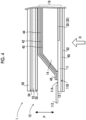
- Fig. 4 is a cross-sectional view taken along line A-A of an example of the radiation detector 10 in Fig. 3 .
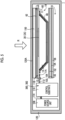
- Fig. 5 is a cross-sectional view of an example of the radiographic imaging apparatus 1 in a state where the radiation detectors 10 of Figs. 3 and 4 are housed in a housing 120.
- the term “on” in the structure of the radiation detector 10 means “on” in a positional relationship with reference to the sensor substrate 12 side in Fig. 4 .
- the conversion layer 14 is provided on the sensor substrate 12.
- the radiographic imaging apparatus 1 of the present embodiment includes a protective layer 62, an antistatic layer 60, a sensor substrate 12, the conversion layer 14, a reinforcing substrate 50, an absorption layer 52, and a radiation-shielding layer 54, and a rigid plate 56. Additionally, as shown in Fig. 5 , in the radiographic imaging apparatus 1, the protective layer 62, the antistatic layer 60, the sensor substrate 12, the conversion layer 14, the reinforcing substrate 50, the absorption layer 52, the radiation-shielding layer 54, and the rigid plate 56 are housed in the housing 120 in this order from the side to which the radiation R is radiated.
- the conversion layer 14 of the present embodiment is provided on a partial region of the sensor substrate 12 including the pixel region 35 on the first surface 11A of the base material 11. In this way, the conversion layer 14 of the present embodiment is not provided on the region of an outer peripheral portion on the first surface 11A of the base material 11.
- a scintillator including CsI is used as an example of the conversion layer 14. It is preferable that such a scintillator includes, for example, CsI:Tl (cesium iodide to which thallium is added) or CsI:Na (cesium iodide to which sodium is added) having an emission spectrum of 400 nm to 700 nm at the time of X-ray radiation.
- the emission peak wavelength in a visible light region of CsI:Tl is 565 nm.
- the conversion layer 14 is directly formed on the sensor substrate 12 as strip-shaped columnar crystals (not shown) by vapor-phase deposition methods, such as a vacuum vapor deposition method, a sputtering method, and a chemical vapor deposition (CVD) method.
- vapor-phase deposition methods such as a vacuum vapor deposition method, a sputtering method, and a chemical vapor deposition (CVD) method.
- CVD chemical vapor deposition
- CsI:Tl is heated and gasified by heating means, such as a resistance heating-type crucible in an environment with a vacuum degree of 0.01 Pa to 10 Pa, and CsI:Tl is deposited on the sensor substrate 12 with the temperature of the sensor substrate 12 as the room temperature (20°C) to 300°C.
- heating means such as a resistance heating-type crucible in an environment with a vacuum degree of 0.01 Pa to 10 Pa
- CsI:Tl is deposited on the sensor substrate 12 with the temperature of the sensor substrate 12 as the room temperature (20°C) to 300°C.
- the thickness of the conversion layer 14 100 ⁇ m to 800 ⁇ m is preferable.
- a buffer layer (not shown) is provided between the sensor substrate 12 and the conversion layer 14.
- PI polyimide
- parylene parylene
- the radiation detector 10 of the present embodiment comprises a pressure-sensitive adhesive layer 40, a reflective layer 42, an adhesive layer 44, and a protective layer 46.
- a direction in which the sensor substrate 12 and the conversion layer 14 are lined up is referred to as a lamination direction (refer to Fig. 4 , a lamination direction P).
- the pressure-sensitive adhesive layer 40 and the reflective layer 42 are provided on the entire conversion layer 14. Additionally, the pressure-sensitive adhesive layer 40 and the reflective layer 42 are not directly provided on the sensor substrate 12.
- the pressure-sensitive adhesive layer 40 of the present embodiment is a light-transmitting layer, and examples of the material of the pressure-sensitive adhesive layer 40 include an acrylic pressure sensitive adhesive, a hot-melt pressure sensitive adhesive, and a silicone adhesive.
- the acrylic pressure sensitive adhesive include urethane acrylate, acrylic resin acrylate, epoxy acrylate, and the like.
- the hot-melt pressure sensitive adhesive include thermoplastics, such as ethylene-vinyl acetate copolymer resin (EVA), ethylene-acrylate copolymer resin (EAA), ethylene-ethyl acrylate copolymer resin (EEA), and ethylene-methyl methacrylate copolymer (EMMA).
- the thickness X of the pressure-sensitive adhesive layer 40 increases (that is, as the interval between the conversion layer 14 and the reflective layer 42 increases), the light converted by the conversion layer 14 is blurred within the pressure-sensitive adhesive layer 40. Therefore, the radiographic image obtained by the radiation detector 10 becomes a blurred image as a result. For that reason, as the thickness of the pressure-sensitive adhesive layer 40 increases, modulation transfer function (MTF) and detective quantum efficiency (DQE) decreases, and the degree of decrease also increases.
- MTF modulation transfer function
- DQE detective quantum efficiency
- the thickness of the pressure-sensitive adhesive layer 40 is made too small, including a case where the pressure-sensitive adhesive layer 40 is not provided, there is a case where a minute air layer is formed between the conversion layer 14 and the reflective layer 42.
- the multiple reflection of the light directed from the conversion layer 14 to the reflective layer 42 occurs between the air layer and the conversion layer 14 and between the air layer and the reflective layer 42.
- the sensitivity of the radiation detector 10 decreases.
- the degree of decrease in DQE becomes larger and is lower than in a case where the thickness of the pressure-sensitive adhesive layer 40 is 0 ⁇ m). That is, in a case where the thickness of the pressure-sensitive adhesive layer 40 exceeds 7 ⁇ m, the DQE is lower than in a case where the pressure-sensitive adhesive layer 40 is not provided. Additionally, in a case where the thickness of the pressure-sensitive adhesive layer 40 is less than 2 ⁇ m, the sensitivity of the radiation detector 10 decreases. Thus, in the present embodiment, the thickness of the pressure-sensitive adhesive layer 40 is set to 2 ⁇ m or more and 7 ⁇ m or less. In addition, the refractive index of the pressure-sensitive adhesive layer 40 is approximately 1.5, although the refractive index depends on the material.
- the pressure-sensitive adhesive layer 40 has a function of fixing the reflective layer 42 to the conversion layer 14.
- the thickness of the pressure-sensitive adhesive layer 40 is 2 ⁇ m or more, it is possible to obtain a sufficient effect of suppressing the deviation of the reflective layer 42 in an in-plane direction (a direction intersecting the thickness direction) with respect to the conversion layer 14.
- the reflective layer 42 is provided on the pressure-sensitive adhesive layer 40 and covers the entire upper surface of the pressure-sensitive adhesive layer 40 itself.
- the reflective layer 42 has a function of reflecting the light converted by the conversion layer 14.
- the reflective layer 42 As a material of the reflective layer 42, it is preferable to use an organic material, and it is preferable to use, for example, at least one of white polyethylene terephthalate (PET), TiO 2 , Al 2 O 3 , foamed white PET, a polyester-based high-reflection sheet, specular reflection aluminum, or the like. Particularly, it is preferable to use the white PET as the material from a viewpoint of reflectivity.
- PET polyethylene terephthalate
- TiO 2 TiO 2
- Al 2 O 3 foamed white PET
- a polyester-based high-reflection sheet a polyester-based high-reflection sheet
- specular reflection aluminum or the like.
- the white PET is obtained by adding a white pigment, such as TiO 2 or barium sulfate, to PET.
- a white pigment such as TiO 2 or barium sulfate
- the polyester-based high-reflection sheet is a sheet (film) having a multilayer structure in which a plurality of thin polyester sheets are laminated.
- the foamed white PET is a white PET of which the surface is porous.
- the thickness of the reflective layer 42 is 10 ⁇ m or more and 40 ⁇ m or less.
- the thickness of the reflective layer 42 is increased, there is a case where a level difference between an upper surface of an outer peripheral portion of the reflective layer 42 and an upper surface of the conversion layer 14 increases and at least one of the adhesive layer 44 or the protective layer 46 is lifted.
- a so-called stiffness state is brought about. Therefore, there is a case where bending does not occur easily along the inclination of the peripheral edge part of the conversion layer 14 and is not easily processed. For that reason, from these viewpoints, in the radiation detector 10 of the present embodiment, in a case where the white PET is used as the material of the reflective layer 42, the thickness of the reflective layer 42 is set to 40 ⁇ m or less as described above.
- the thickness of the reflective layer 42 decreases.
- reflectivity decreases.
- the quality of a radiographic image to be obtained by the radiation detector 10 also tends to deteriorate.
- the lower limit of the thickness of the reflective layer 42 in consideration of a desired reflectivity (for example, 80%).
- the thickness of the reflective layer 42 is set to 10 ⁇ m or more as described above.
- the adhesive layer 44 is provided from above a region in the vicinity of an outer peripheral portion of the conversion layer 14 in the sensor substrate 12 to a region covering an end part of the reflective layer 42.
- the adhesive layer 44 that covers the entire conversion layer 14 in which the pressure-sensitive adhesive layer 40 and the reflective layer 42 are provided is directly fixed (adhered) to the surface of the sensor substrate 12.
- the adhesive layer 44 has a function of fixing the reflective layer 42 to the sensor substrate 12 and the conversion layer 14.
- the adhesive layer 44 has a function of fixing the protective layer 46.
- Examples of the material of the adhesive layer 44 include the same materials as the pressure-sensitive adhesive layer 40.
- the adhesive force of the adhesive layer 44 is stronger than the adhesive force of the pressure-sensitive adhesive layer 40.
- the protective layer 46 is provided on the adhesive layer 44, and the protective layer 46 of the present embodiment covers the entire upper surface of the adhesive layer 44 that covers the conversion layer 14 in a state in which the upper surface thereof is covered with the pressure-sensitive adhesive layer 40 and the reflective layer 42.
- the protective layer 46 has a function of protecting the conversion layer 14 from moisture, such as humidity. Additionally, the protective layer 46 has a function of fixing the reflective layer 42 to the sensor substrate 12 and the conversion layer 14 together with the adhesive layer 44.
- Examples of the material of the protective layer 46 include organic films, and specifically include PET, polyphenylene sulfide (PPS), biaxially oriented polypropylene film (OPP), polyethylene naphthalate (PEN), PI, and the like. Additionally, as the protective layer 46, an ALPET (registered trademark) sheet obtained by laminating aluminum, for example by causing aluminum foil to adhere to an insulating sheet (film), such as polyethylene terephthalate may be used.
- PET polyphenylene sulfide
- OPP biaxially oriented polypropylene film
- PEN polyethylene naphthalate
- PI polyethylene naphthalate
- an ALPET registered trademark
- the antistatic layer 60 and the protective layer 62 are provided on the side of the laminate 19 to which the radiation R is radiated, in other words, on a second surface 11B side of the base material 11 in the sensor substrate 12.
- the antistatic layer 60 is provided on the second surface 11B of the base material 11 and has a function of preventing the sensor substrate 12 from being charged.
- a film using an antistatic paint "Colcoat” (product name: manufactured by Colcoat Co., Ltd.) is used as the antistatic layer 60.
- the protective layer 62 is provided on the side of the antistatic layer 60 opposite to a side in contact with the base material 11, and has a function of preventing the sensor substrate 12 from being charged, similar to the antistatic layer 60.
- an Alpet (registered trademark) sheet in which aluminum is laminated by causing an aluminum foil to adhere to an insulating sheet (film) is used as the protective layer 62.
- the protective layer 62 is connected to a ground for discharging the electric charges that stay in the antistatic layer 60 and the protective layer 62.
- the ground a so-called frame ground in which the housing 120 is connected to the protective layer 62 as a ground is used, but the ground connecting the protective layer 62 is not limited to the present embodiment and may be a part that supplies a constant potential. Additionally, earth may be applied instead of the ground.
- the buffer member 150 is provided between the protective layer 62 and the top plate 120A having an irradiation surface to which the radiation R is radiated in the housing 120.
- the buffer member 150 has a function of absorbing an impact due to a load of a subject applied to the top plate 120A of the housing 120 and absorbing the influence of deflection of the top plate 120A.
- the buffer member 150 of the present embodiment has a function of absorbing irregularities generated in the housing 120A. Examples of the buffer member 150 include a material having a Shore E hardness, which is a durometer hardness, similar to the absorption layer 52 described below.
- the protective layer 62 is not limited to a layer having an antistatic function, and may have at least one of a moistureproof function or an antistatic function for the pixel region 35.
- a parylene (registered trademark) film, an insulating sheet such as PET, or the like can be used as the protective layer.
- the reinforcing substrate 50, the absorption layer 52, the radiation-shielding layer 54, and the rigid plate 56 are provided on the side of the laminate 19 opposite to the side to which the radiation R is radiated, in other words, on the side of the conversion layer 14 opposite to the side in contact with the sensor substrate 12.
- the reinforcing substrate 50, the absorption layer 52, the radiation-shielding layer 54, and the rigid plate 56 are laminated on the conversion layer 14 in this order.
- the absorption layer 52 has a function of absorbing the irregularities generated in the conversion layer 14 of the laminate 19 due to the irregularities of the laminate 19 of the radiation detector 10, the housing 120, or the like, thereby suppressing the propagation of the irregularities to the sensor substrate 12.
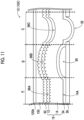
- Fig. 11 shows a radiation detector 10X (radiographic imaging apparatus 1X) in a state where the reinforcing substrate 50 and the absorption layer 52 are not provided, unlike the radiation detector 10 of the present embodiment.
- a region A of Fig. 11 is an example of a region including irregularities 96A caused by the conversion layer 14.
- the conversion layer 14 is formed as columnar crystals 14A on the sensor substrate 12.
- the radiation-shielding layer 54 side of the conversion layer 14 is tips of the columnar crystals 14A.
- the base material 11 of the sensor substrate 12 is relatively soft and easily deflected as described above, as shown in the region A of Fig. 11 , there is a case where the irregularities of the tips of the columnar crystals 14A are propagated to the sensor substrate 12 side, and the irregularities 96A are generated not on the distal end side of the conversion layer 14 but on the sensor substrate 12 on the root side. So to speak, there is a case where the irregularities of the columnar crystals 14A of the conversion layer 14 are transferred to the sensor substrate 12 on the root side.
- the region B of Fig. 11 is an example of a region including irregularities 96B caused by bubbles 90 generated in the radiation-shielding layer 54.
- irregularities are generated between the radiation-shielding layer 54 and the rigid plate 56 due to the bubbles 90 generated in the radiation-shielding layer 54.
- the radiation-shielding layer 54 enters the conversion layer 14 side and the irregularities are generated in the conversion layer 14.
- the influence of the irregularities generated by the radiation-shielding layer 54 is propagated, so that the irregularities 96B are generated in the sensor substrate 12.
- a region C of Fig. 11 is an example of a region including irregularities 96C caused by the irregularities 92 of the rigid plate 56.
- fine irregularities are generated in the surface of the rigid plate 56.
- an example of a state where the irregularities 92 in the region C of Fig. 11 are irregularities due to the recesses of the rigid plate 56 and the irregularities are generated in the laminate 19 due to the irregularities 92 of the rigid plate 56 is shown.
- the base material 11 of the sensor substrate 12 is relatively easily deflected. Therefore, for example, in a case where t may be softer than the other layers (members) forming the radiation detector 10X, there is a case where the influence of irregularities caused by the radiographic imaging apparatus 1X such as the laminate 19 or the housing 120 are propagated and the irregularities are generated in the sensor substrate 12.
- the influence of the irregularities are likely to propagate to the sensor substrate 12, and the irregularities are likely to be generated in the sensor substrate 12.
- the irregularities generated in the sensor substrate 12 appear as image unevenness in a radiographic image obtained by the radiation detector 10X.
- the absorption layer 52 of the present embodiment is provided on the side of the laminate 19 opposite to the side where the radiation R is radiated, and in the radiation detector 10 of the present embodiment, on the conversion layer 14 as shown in Figs. 3 to 5 .
- the absorption layer 52 has a function of absorbing the influence of the irregularities caused by the laminate 19, the housing 120, or the like and suppressing the influence of the irregularities from being propagated to the sensor substrate 12.
- the absorption layer 52 is a layer made of a soft material for absorbing the influence of the irregularities and has a durometer hardness smaller than the durometer hardness of the entire laminate 19.
- a hardness measuring method in the present embodiment is obtained by setting a sample in a type E durometer conforming to JIS K6253 and performing a measurement 15 seconds after the contact of a push needle.
- Specific materials for the absorption layer 52 include foams such as urethane foam, polyethylene, rubber sponge, and silicon foam, urethane gel, and the like.
- the absorption layer 52 is deformed in accordance with the irregularities of the columnar crystal 14A even in the region A including the irregularities of the columnar crystals 14A of the conversion layer 14. Accordingly, the irregularities are not propagated to the sensor substrate 12.
- the absorption layer 52 is deformed in accordance with the bubbles 90 even in the region B where the bubbles 90 are generated by the radiation-shielding layer 54. Accordingly, the irregularities caused by the bubbles 90 are not propagated to the sensor substrate 12.
- the absorption layer 52 is deformed in accordance with the irregularities 92 even in the region C where the irregularities 92 of the rigid plate 56 are generated. Accordingly, the irregularities caused by the irregularities 92 are not propagated to the sensor substrate 12.
- the absorption layer 52 has the shape according to the irregularities generated in the conversion layer 14 of the laminate 19 due to the irregularities of the laminate 19 of the radiation detector 10, the housing 120, or the like. Therefore, the propagation of the irregularities to the sensor substrate 12 can be suppressed.
- the absorption layer 52 of the present embodiment has the same size (area) as the first surface 11A side of the base material 11 in the sensor substrate 12.
- the size of the absorption layer 52 is not limited to the form shown in Figs. 3 to 5 but is preferably larger than that of the sensor substrate 12 and preferably has at least an area larger than that of the conversion layer 14.
- the thickness of the absorption layer 52 (the thickness in the lamination direction P) is determined in accordance with a size assumed as the size of the irregularities caused by the laminate 19 or the housing 120, for example, the bubbles 90 or the irregularities 92 shown in Fig. 5 .
- the absorption layer 52 preferably has at least a thickness larger than the size of the bubbles 90 or the irregularities 92.
- the absorption layer 52 preferably has an antistatic function for preventing the sensor substrate 12 from being charged, or has conductivity, and preferably has a surface resistance value of 10 13 ⁇ or less.
- the absorption layer 52 having conductivity for example, a material in which conductive carbon is kneaded into a polyethylene resin can be applied.
- the reinforcing substrate 50 has a function of dispersing a compressive force applied to the absorption layer 52 in an in-plane direction of the absorption layer 52, and disperses the compressive force applied to the absorption layer 52, thereby uniformly compressing the absorption layer 52.
- the reinforcing substrate 50 preferably uses a material having a bending elastic modulus of 150 MPa or more and 2,500 MPa or less.
- a method of measuring the bending elastic modulus is based on, for example, JIS K 7171:2016 Standard.
- the reinforcing substrate 50 preferably has a higher bending stiffness than the base material 11 from the viewpoint of dispersing the compressive force applied to the absorption layer 52 in the in-plane direction of the absorption layer 52.
- the bending stiffness also becomes low.
- the thickness of the reinforcing substrate 50 should be made large, and the thickness of the entire radiation detector 10 increases.
- the thickness of the reinforcing substrate 50 tends to be relatively large in a case where a bending stiffness exceeding 140,000 Pacm 4 is to be obtained. For that reason, in view of obtaining appropriate stiffness and considering the thickness of the entire radiation detector 10, the material used for the reinforcing substrate 50 preferably has a bending elastic modulus of 150 MPa or more and 2,500 MPa or less. Additionally, the bending stiffness of the reinforcing substrate 50 is preferably 540 Pacm 4 or more and 140,000 Pacm 4 or less.
- the reinforcing substrate 50 of the present embodiment is a substrate having plastic as a material.
- the plastic used as the material for the reinforcing substrate 50 is preferably a thermoplastic resin, and include at least one of polycarbonate (PC), PET, styrol, acrylic, polyacetase, nylon, polypropylene, acrylonitrile butadiene styrene (ABS), engineering plastics, or polyphenylene ether.
- the reinforcing substrate 50 is more preferably at least one of polypropylene, ABS, engineering plastics, PET, or polyphenylene ether among these, is more preferably at least one of styrol, acrylics, polyacetase, or nylon, and is more preferably at least one of PC or PET.
- the radiation-shielding layer 54 provided on the reinforcing substrate 50 has a function of shielding the radiation R transmitted through the laminate 19 and suppressing the radiation R transmitted to the outside of the housing 120.
- Examples of the radiation-shielding layer 54 include a plate such as lead.
- the rigid plate 56 provided on the radiation-shielding layer 54 supports the radiation detector 10.
- the rigid plate 56 has a higher stiffness than the sensor substrate 12, and for example, carbon or the like is used.
- the housing 120 shown in Fig. 5 which houses the radiation detector 10 of the present embodiment, is preferably lightweight, has a low absorbance of radiation R, particularly X-rays, and has a high stiffness, and is preferably made of a material having a sufficiently high elastic modulus.
- a material having a bending elastic modulus of 10,000 MPa or more As the material of the housing 120, carbon or carbon fiber reinforced plastics (CFRP) having a bending elastic modulus of about 20,000 to 60,000 MPa can be suitably used.
- CFRP carbon or carbon fiber reinforced plastics
- a load from a subject is applied to the top plate 120A of the housing 120.
- the stiffness of the housing 120 is insufficient, there are concerns that problems may occur such that the sensor substrate 12 is deflected due to the load from the subject and the pixels 30 are damaged.
- the radiation detector 10 By accommodating the radiation detector 10 inside the housing 120 consisting of a material having a bending elastic modulus of 10,000 MPa or more, it is possible to suppress the deflection of the sensor substrate 12 due to the load from the subject.
- the radiation detector 10, the power source unit 108, and a control substrate 110 are provided side by side in a direction intersecting an incidence direction of radiation R within the housing 120.
- the control substrate 110 is a substrate in which an image memory 380 for storing image data according to the electric charges read from the pixels 30 of the sensor substrate 12, a control unit 382 for controlling reading or the like of the electric charges from the pixels 30, and the like are formed, and is electrically connected to the pixels 30 of the sensor substrate 12 by a flexible cable 112 including a plurality of signal wiring lines.
- the control substrate 110 is a so-called chip on film (COF) in which a drive unit 103 for controlling the switching states of the TFTs 32 of the pixels 30 under the control of the control unit 382, and a signal processing unit 104 for creating and outputting image data according to the electric charges read from the pixels 30 are provided on the flexible cable 112.
- COF chip on film
- the drive unit 103 or the signal processing unit 104 may be formed in the control substrate 110.
- control substrate 110 is connected to the power source unit 108, which supplies electrical power to the image memory 380, the control unit 382, and the like that are formed in the control substrate 110, by a power source line 114.
- each of the power source unit 108 and the control substrate 110 is thicker than the radiation detector 10.
- the thickness of the portion of the housing 120 in which the radiation detector 10 is provided may be smaller than the thickness of the portion of the housing 120 in which each of the power source unit 108 and the control substrate 110 is provided.
- the form of the boundary part 120B is preferably in a state of having an inclination.
- the materials of the housing 120 may be different in the portion of the housing 120 in which each of the power source unit 108 and the control substrate 110 is provided and the portion of the housing 120 in which the radiation detector 10 is provided.
- the portion of the housing 120 in which each of the power source unit 108 and the control substrate 110 is provided and the portion of the housing 120 in which the radiation detector 10 is provided may be separated configured.
- the radiation detector 10, the control substrate 110, and the power source unit 108 may be housed in the housing 120 in a line in order from the top plate 120A side to which the radiation R is radiated.
- the radiation detector 10 of the present embodiment includes the sensor substrate 12 in which the plurality of pixels 30 for accumulating the electric charge charges generated in response to the light converted from the radiation R are formed in the pixel region 35 of the flexible base material 11, the conversion layer 14 that is provided on the first surface 11A provided with the pixel region 35 of the base material 11 and converts the radiation R into light, the absorption layer 52 that is provided on the side opposite to the side to which the radiation R is radiated in the laminate 19 in which the sensor substrate 12 and the conversion layer 14 are laminated and absorbs the influence of the irregularities generated on the conversion layer 14 on the sensor substrate 12, and the rigid plate 56 that is provided on the side opposite to the side of the absorption layer 52 facing the laminate 19 and has a higher stiffness than the sensor substrate 12.
- the absorption layer 52 has the shape according to the irregularities generated in the conversion layer 14 of the laminate 19 due to the irregularities of the laminate 19 of the radiation detector 10, the housing 120, or the like. Therefore, the influence of the irregularities on the sensor substrate 12 can be suppressed. Therefore, by suppressing the generation of the irregularities on the sensor substrate 12, according to the radiation detector 10 of the present embodiment, the image unevenness or the like of the radiographic image caused by the irregularities of the sensor substrate 12 can be suppressed, and the quality of the radiographic image can be improved.
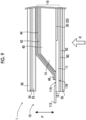
- the position where the reinforcing substrate 50 is provided is not limited to the position shown in the present embodiment (refer to Fig. 4 ), and as shown in Fig. 9 , the reinforcing substrate 50 may be provided at a position on the opposite side of the laminate 19, specifically, on the side of the antistatic layer 60 and the protective layer 62.
- the present invention is not limited to the example shown in Fig. 9 , and for example, a form may be adopted in which the reinforcing substrate 50 may be provided between the antistatic layer 60 and the sensor substrate 12. This embodiments is, however, not according to the claimed invention.
- the radiation detector 10 may be a penetration side sampling (PSS) type radiation detector 10 (radiographic imaging apparatus 1) in which the radiation R is radiated from the conversion layer 14 side.
- the absorption layer 52 that absorbs the influence of the irregularities generated on the conversion layer 14 on the sensor substrate 12 may be provided on the side opposite to the side on which the radiation R is radiated in the laminate 19 in which the sensor substrate 12 and the conversion layer 14 are laminated.
- the rigid plate 56 which is provided on the side opposite to the side of the absorption layer 52 facing the laminate 19 and has a higher stiffness than the sensor substrate 12, is provided.
- the absorption layer 52 has the shape according to the irregularities generated in the conversion layer 14 of the laminate 19 due to the irregularities of the laminate 19 of the radiation detector 10 or the housing 120 and the like. Therefore, the influence of the irregularities on the sensor substrate 12 can be suppressed. Therefore, by suppressing the generation of the irregularities on the sensor substrate 12, according to the radiation detector 10 of the present embodiment, the image unevenness or the like of the radiographic image caused by the irregularities of the sensor substrate 12 can be suppressed, and the quality of the radiographic image can be improved.
- the pixels 30 are two-dimensionally arranged on a matrix.
- the invention is not limited to the aspect, and for example, the pixels 30 may be one-dimensionally arranged or may be arranged in a honeycomb shape.
- the shape of the pixels is also not limited, and may be a rectangular shape, or may be a polygonal shape, such as a hexagonal shape.
- the shape of the pixel region 35 is also not limited.
- the shape or the like of the conversion layer 14 is not limited to the above embodiments.
- the shape of the conversion layer 14 may not be the same shape as the pixel region 35.
- the shape of the pixel region 35 may not be a rectangular shape but may be, for example, other polygonal shapes or a circular shape.
- the conversion layer 14 of the radiation detector 10 is the scintillator including CsI
- the conversion layer 14 may be a scintillator in which GOS (Gd 2 O 2 S:Tb) or the like is dispersed in a binder, such as resin.
- GOS Ga 2 O 2 S:Tb
- the conversion layer 14 using GOS is formed, for example, by directly applying the binder having the GOS dispersed therein onto the sensor substrate 12, the peeling layer, and the like and then drying and solidifying the binder.
- a Giza method of applying an application liquid to a region where the conversion layer 14 is formed while controlling the thickness of an applied film may be adopted.
- surface treatment for activating the surface of the pixel region 35 may be performed before the binder having the GOS dispersed therein is applied.
- an interlayer insulating film may be provided as a surface protective film on the surface of the pixel region 35.
Landscapes
- Health & Medical Sciences (AREA)
- Life Sciences & Earth Sciences (AREA)
- Physics & Mathematics (AREA)
- High Energy & Nuclear Physics (AREA)
- Molecular Biology (AREA)
- Medical Informatics (AREA)
- Engineering & Computer Science (AREA)
- General Physics & Mathematics (AREA)
- Spectroscopy & Molecular Physics (AREA)
- Pathology (AREA)
- Surgery (AREA)
- Optics & Photonics (AREA)
- Biophysics (AREA)
- Radiology & Medical Imaging (AREA)
- Biomedical Technology (AREA)
- Heart & Thoracic Surgery (AREA)
- Nuclear Medicine, Radiotherapy & Molecular Imaging (AREA)
- Animal Behavior & Ethology (AREA)
- General Health & Medical Sciences (AREA)
- Public Health (AREA)
- Veterinary Medicine (AREA)
- Chemical & Material Sciences (AREA)
- Crystallography & Structural Chemistry (AREA)
- Mathematical Physics (AREA)
- Measurement Of Radiation (AREA)
Claims (10)
- Röntgenbildgerät (10, 10X), aufweisend:ein Sensorsubstrat (12), in dem eine Vielzahl von Pixeln zum Akkumulieren elektrischer Ladungen, die als Reaktion auf aus Strahlung umgewandeltes Licht erzeugt werden, in einem Pixelbereich eines flexiblen Basismaterials (11) ausgebildet ist;eine Umwandlungsschicht (14), die auf einer Oberfläche des mit dem Pixelbereich versehenen Basismaterials (11) vorgesehen ist und die Strahlung in Licht umwandelt; undeine Absorptionsschicht (52), die auf der dem Sensorsubstrat (12) gegenüberliegenden Seite der Umwandlungsschicht (14) vorgesehen ist, wobei die Absorptionsschicht (52) auf einer Seite vorgesehen ist, die einer Seite gegenüberliegt, auf die die Strahlung in einem Laminat (19) gestrahlt wird, in dem das Sensorsubstrat (12) und die Umwandlungsschicht (14) laminiert sind, und den Einfluss von Unregelmäßigkeiten absorbiert, die auf der Umwandlungsschicht (14) auf dem Sensorsubstrat (12) erzeugt werden;eine starre Platte (56), die auf einer Seite der Absorptionsschicht (52) vorgesehen ist, die einer dem Laminat (19) zugewandten Seite gegenüberliegt, und die eine höhere Steifigkeit als das Sensorsubstrat (12) aufweist; und gekennzeichnet durch:ein Gehäuse (120), in dem das Röntgenbildgerät (10, 10X) in der Reihenfolge des Laminats (19), der Absorptionsschicht (52) und der starren Platte (56) von der Seite, auf die die Strahlung eingestrahlt wird, untergebracht ist; undein Verstärkungssubstrat (50), das zwischen der Absorptionsschicht (52) und dem Laminat (19) vorgesehen ist und das eine auf die Absorptionsschicht (52) ausgeübte Druckkraft in einer Richtung innerhalb der Ebene der Absorptionsschicht (52) verteilt.
- Röntgenbildgerät nach Anspruch 1,
wobei eine Durometerhärte der Absorptionsschicht (52) kleiner ist als eine Durometerhärte des gesamten Laminats (19). - Röntgenbildgerät nach einem der Ansprüche 1 bis 2,
wobei die Absorptionsschicht (52) einen Oberflächenwiderstandswert von 1013 Ω oder weniger aufweist. - Röntgenbildgerät nach einem der vorhergehenden Ansprüche,
wobei das Verstärkungssubstrat (50) einen Biege-Elastizitätsmodul von 150 MPa oder mehr und 2.500 MPa oder weniger aufweist. - Röntgenbildgerät nach einem der Ansprüche 1 bis 4,
wobei das Verstärkungssubstrat (50) eine Biegesteifigkeit von 540 Pacm4 oder mehr und 140.000 Pacm4 oder weniger aufweist. - Röntgenbildgerät nach einem der Ansprüche 1 bis 5, ferner umfassend:
eine strahlungsabschirmende Schicht (54), die die Strahlung abschirmt und zwischen der Absorptionsschicht (52) und der starren Platte (56) vorgesehen ist. - Röntgenbildgerät nach einem der Ansprüche 1 bis 6,
wobei die starre Platte (56) eine Platte mit Kohlenstoff als Material ist. - Röntgenbildgerät nach einem der Ansprüche 1 bis 7, ferner umfassend:
ein Pufferelement (150), das auf einer Seite des Laminats (19) vorgesehen ist, auf die die Strahlung auftrifft. - Röntgenbildgerät nach einem der Ansprüche 1 bis 8,
wobei die Umwandlungsschicht (14) säulenförmige Kristalle von CsI enthält. - Röntgenbildgerät nach einem der Ansprüche 1 bis 9, ferner umfassend:eine Steuereinheit (382), die ein Steuersignal zum Auslesen der in der Vielzahl von Pixeln angesammelten elektrischen Ladungen ausgibt;eine Ansteuereinheit (103), die die elektrischen Ladungen aus der Vielzahl von Pixeln in Übereinstimmung mit dem Steuersignal ausliest; undeine Signalverarbeitungseinheit (104), die elektrische Signale entsprechend den von der Vielzahl von Pixeln ausgelesenen elektrischen Ladungen empfängt und Bilddaten entsprechend den empfangenen elektrischen Signalen erzeugt, um die Bilddaten an die Steuereinheit (382) auszugeben.
Applications Claiming Priority (2)
| Application Number | Priority Date | Filing Date | Title |
|---|---|---|---|
| JP2019086596 | 2019-04-26 | ||
| PCT/JP2020/017770 WO2020218538A1 (ja) | 2019-04-26 | 2020-04-24 | 放射線検出器及び放射線画像撮影装置 |
Publications (3)
| Publication Number | Publication Date |
|---|---|
| EP3961269A1 EP3961269A1 (de) | 2022-03-02 |
| EP3961269A4 EP3961269A4 (de) | 2022-06-01 |
| EP3961269B1 true EP3961269B1 (de) | 2024-12-25 |
Family
ID=72942777
Family Applications (1)
| Application Number | Title | Priority Date | Filing Date |
|---|---|---|---|
| EP20794058.6A Active EP3961269B1 (de) | 2019-04-26 | 2020-04-24 | Strahlungsdetektor und röntgenbildgebungsvorrichtung |
Country Status (6)
| Country | Link |
|---|---|
| US (1) | US11747490B2 (de) |
| EP (1) | EP3961269B1 (de) |
| JP (1) | JP7167322B2 (de) |
| CN (1) | CN113767306B (de) |
| TW (1) | TWI841726B (de) |
| WO (1) | WO2020218538A1 (de) |
Families Citing this family (1)
| Publication number | Priority date | Publication date | Assignee | Title |
|---|---|---|---|---|
| JP2024165301A (ja) * | 2023-05-17 | 2024-11-28 | キヤノン株式会社 | 放射線画像撮影装置 |
Family Cites Families (11)
| Publication number | Priority date | Publication date | Assignee | Title |
|---|---|---|---|---|
| JP3815766B2 (ja) | 1998-01-28 | 2006-08-30 | キヤノン株式会社 | 二次元撮像装置 |
| JP2008212343A (ja) * | 2007-03-02 | 2008-09-18 | General Electric Co <Ge> | 軽量で頑丈なディジタルx線検出器 |
| US7495227B2 (en) * | 2007-07-10 | 2009-02-24 | General Electric Company | Digital x-ray detectors |
| JP2012128091A (ja) * | 2010-12-14 | 2012-07-05 | Fujifilm Corp | 放射線画像撮影装置 |
| JP5711700B2 (ja) | 2011-07-20 | 2015-05-07 | 富士フイルム株式会社 | 放射線撮像装置 |
| JP5827856B2 (ja) * | 2011-09-28 | 2015-12-02 | 富士フイルム株式会社 | カセッテ |
| JP2013217769A (ja) | 2012-04-09 | 2013-10-24 | Canon Inc | 放射線検出装置 |
| US9581701B2 (en) * | 2014-12-16 | 2017-02-28 | Carestream Health, Inc. | Impact protection for wireless digital detector glass panel |
| KR20180055307A (ko) * | 2016-11-16 | 2018-05-25 | 삼성전자주식회사 | 엑스선 디텍터 및 이를 포함하는 엑스선 촬영장치 |
| JP6646002B2 (ja) * | 2017-03-22 | 2020-02-14 | 富士フイルム株式会社 | 放射線検出器及び放射線画像撮影装置 |
| JP2019086596A (ja) | 2017-11-02 | 2019-06-06 | キヤノン株式会社 | 画像形成装置 |
-
2020
- 2020-04-24 EP EP20794058.6A patent/EP3961269B1/de active Active
- 2020-04-24 JP JP2021516277A patent/JP7167322B2/ja active Active
- 2020-04-24 TW TW109113945A patent/TWI841726B/zh active
- 2020-04-24 CN CN202080031693.4A patent/CN113767306B/zh active Active
- 2020-04-24 WO PCT/JP2020/017770 patent/WO2020218538A1/ja not_active Ceased
-
2021
- 2021-10-11 US US17/497,991 patent/US11747490B2/en active Active
Also Published As
| Publication number | Publication date |
|---|---|
| EP3961269A4 (de) | 2022-06-01 |
| TWI841726B (zh) | 2024-05-11 |
| US11747490B2 (en) | 2023-09-05 |
| JP7167322B2 (ja) | 2022-11-08 |
| CN113767306B (zh) | 2024-03-26 |
| TW202105756A (zh) | 2021-02-01 |
| CN113767306A (zh) | 2021-12-07 |
| US20220082714A1 (en) | 2022-03-17 |
| WO2020218538A1 (ja) | 2020-10-29 |
| EP3961269A1 (de) | 2022-03-02 |
| JPWO2020218538A1 (de) | 2020-10-29 |
Similar Documents
| Publication | Publication Date | Title |
|---|---|---|
| JP7087164B2 (ja) | 放射線検出器及び放射線画像撮影装置 | |
| JP7376636B2 (ja) | 放射線検出器、放射線画像撮影装置及び放射線検出器の製造方法 | |
| US11428827B2 (en) | Radiation detector, radiographic imaging apparatus, and manufacturing method | |
| CN110286397B (zh) | 放射线检测器、放射线图像摄影装置以及制造方法 | |
| JP7030956B2 (ja) | 放射線検出器及び放射線画像撮影装置 | |
| JP7342184B2 (ja) | 放射線検出器、放射線画像撮影装置及び放射線検出器の製造方法 | |
| EP3859401B1 (de) | Strahlungsdetektor, strahlungsbildgebungsvorrichtung und herstellungsverfahren | |
| US11747490B2 (en) | Radiation detector and radiographic imaging apparatus | |
| US11802981B2 (en) | Method of manufacturing radiation detector and radiographic imaging apparatus | |
| US20190298282A1 (en) | Radiation detector and radiographic imaging apparatus | |
| US11766227B2 (en) | Radiation detector, radiographic imaging apparatus, and method of manufacturing radiation detector | |
| US11633162B2 (en) | Radiation detector and radiographic imaging apparatus | |
| US20220401045A1 (en) | Radiation detector, radiographic imaging apparatus, and method of manufacturing radiation detector |
Legal Events
| Date | Code | Title | Description |
|---|---|---|---|
| STAA | Information on the status of an ep patent application or granted ep patent |
Free format text: STATUS: THE INTERNATIONAL PUBLICATION HAS BEEN MADE |
|
| PUAI | Public reference made under article 153(3) epc to a published international application that has entered the european phase |
Free format text: ORIGINAL CODE: 0009012 |
|
| STAA | Information on the status of an ep patent application or granted ep patent |
Free format text: STATUS: REQUEST FOR EXAMINATION WAS MADE |
|
| 17P | Request for examination filed |
Effective date: 20211025 |
|
| AK | Designated contracting states |
Kind code of ref document: A1 Designated state(s): AL AT BE BG CH CY CZ DE DK EE ES FI FR GB GR HR HU IE IS IT LI LT LU LV MC MK MT NL NO PL PT RO RS SE SI SK SM TR |
|
| A4 | Supplementary search report drawn up and despatched |
Effective date: 20220429 |
|
| RIC1 | Information provided on ipc code assigned before grant |
Ipc: A61B 6/00 20060101ALI20220422BHEP Ipc: G01T 1/202 20060101ALI20220422BHEP Ipc: G01T 1/20 20060101AFI20220422BHEP |
|
| DAV | Request for validation of the european patent (deleted) | ||
| DAX | Request for extension of the european patent (deleted) | ||
| GRAP | Despatch of communication of intention to grant a patent |
Free format text: ORIGINAL CODE: EPIDOSNIGR1 |
|
| STAA | Information on the status of an ep patent application or granted ep patent |
Free format text: STATUS: GRANT OF PATENT IS INTENDED |
|
| INTG | Intention to grant announced |
Effective date: 20240502 |
|
| GRAJ | Information related to disapproval of communication of intention to grant by the applicant or resumption of examination proceedings by the epo deleted |
Free format text: ORIGINAL CODE: EPIDOSDIGR1 |
|
| STAA | Information on the status of an ep patent application or granted ep patent |
Free format text: STATUS: REQUEST FOR EXAMINATION WAS MADE |
|
| GRAP | Despatch of communication of intention to grant a patent |
Free format text: ORIGINAL CODE: EPIDOSNIGR1 |
|
| STAA | Information on the status of an ep patent application or granted ep patent |
Free format text: STATUS: GRANT OF PATENT IS INTENDED |
|
| INTC | Intention to grant announced (deleted) | ||
| INTG | Intention to grant announced |
Effective date: 20240909 |
|
| P01 | Opt-out of the competence of the unified patent court (upc) registered |
Free format text: CASE NUMBER: APP_49238/2024 Effective date: 20240829 |
|
| GRAS | Grant fee paid |
Free format text: ORIGINAL CODE: EPIDOSNIGR3 |
|
| GRAA | (expected) grant |
Free format text: ORIGINAL CODE: 0009210 |
|
| STAA | Information on the status of an ep patent application or granted ep patent |
Free format text: STATUS: THE PATENT HAS BEEN GRANTED |
|
| AK | Designated contracting states |
Kind code of ref document: B1 Designated state(s): AL AT BE BG CH CY CZ DE DK EE ES FI FR GB GR HR HU IE IS IT LI LT LU LV MC MK MT NL NO PL PT RO RS SE SI SK SM TR |
|
| REG | Reference to a national code |
Ref country code: GB Ref legal event code: FG4D |
|
| REG | Reference to a national code |
Ref country code: CH Ref legal event code: EP |
|
| REG | Reference to a national code |
Ref country code: DE Ref legal event code: R096 Ref document number: 602020043745 Country of ref document: DE |
|
| REG | Reference to a national code |
Ref country code: IE Ref legal event code: FG4D |
|
| REG | Reference to a national code |
Ref country code: LT Ref legal event code: MG9D |
|
| PG25 | Lapsed in a contracting state [announced via postgrant information from national office to epo] |
Ref country code: HR Free format text: LAPSE BECAUSE OF FAILURE TO SUBMIT A TRANSLATION OF THE DESCRIPTION OR TO PAY THE FEE WITHIN THE PRESCRIBED TIME-LIMIT Effective date: 20241225 |
|
| PG25 | Lapsed in a contracting state [announced via postgrant information from national office to epo] |
Ref country code: FI Free format text: LAPSE BECAUSE OF FAILURE TO SUBMIT A TRANSLATION OF THE DESCRIPTION OR TO PAY THE FEE WITHIN THE PRESCRIBED TIME-LIMIT Effective date: 20241225 |
|
| PG25 | Lapsed in a contracting state [announced via postgrant information from national office to epo] |
Ref country code: BG Free format text: LAPSE BECAUSE OF FAILURE TO SUBMIT A TRANSLATION OF THE DESCRIPTION OR TO PAY THE FEE WITHIN THE PRESCRIBED TIME-LIMIT Effective date: 20241225 |
|
| PG25 | Lapsed in a contracting state [announced via postgrant information from national office to epo] |
Ref country code: NO Free format text: LAPSE BECAUSE OF FAILURE TO SUBMIT A TRANSLATION OF THE DESCRIPTION OR TO PAY THE FEE WITHIN THE PRESCRIBED TIME-LIMIT Effective date: 20250325 |
|
| PG25 | Lapsed in a contracting state [announced via postgrant information from national office to epo] |
Ref country code: LV Free format text: LAPSE BECAUSE OF FAILURE TO SUBMIT A TRANSLATION OF THE DESCRIPTION OR TO PAY THE FEE WITHIN THE PRESCRIBED TIME-LIMIT Effective date: 20241225 Ref country code: GR Free format text: LAPSE BECAUSE OF FAILURE TO SUBMIT A TRANSLATION OF THE DESCRIPTION OR TO PAY THE FEE WITHIN THE PRESCRIBED TIME-LIMIT Effective date: 20250326 |
|
| PGFP | Annual fee paid to national office [announced via postgrant information from national office to epo] |
Ref country code: FR Payment date: 20250310 Year of fee payment: 6 |
|
| PG25 | Lapsed in a contracting state [announced via postgrant information from national office to epo] |
Ref country code: RS Free format text: LAPSE BECAUSE OF FAILURE TO SUBMIT A TRANSLATION OF THE DESCRIPTION OR TO PAY THE FEE WITHIN THE PRESCRIBED TIME-LIMIT Effective date: 20250325 |
|
| REG | Reference to a national code |
Ref country code: NL Ref legal event code: MP Effective date: 20241225 |
|
| PG25 | Lapsed in a contracting state [announced via postgrant information from national office to epo] |
Ref country code: NL Free format text: LAPSE BECAUSE OF FAILURE TO SUBMIT A TRANSLATION OF THE DESCRIPTION OR TO PAY THE FEE WITHIN THE PRESCRIBED TIME-LIMIT Effective date: 20241225 |
|
| REG | Reference to a national code |
Ref country code: AT Ref legal event code: MK05 Ref document number: 1754630 Country of ref document: AT Kind code of ref document: T Effective date: 20241225 |
|
| PG25 | Lapsed in a contracting state [announced via postgrant information from national office to epo] |
Ref country code: SM Free format text: LAPSE BECAUSE OF FAILURE TO SUBMIT A TRANSLATION OF THE DESCRIPTION OR TO PAY THE FEE WITHIN THE PRESCRIBED TIME-LIMIT Effective date: 20241225 |
|
| PG25 | Lapsed in a contracting state [announced via postgrant information from national office to epo] |
Ref country code: PL Free format text: LAPSE BECAUSE OF FAILURE TO SUBMIT A TRANSLATION OF THE DESCRIPTION OR TO PAY THE FEE WITHIN THE PRESCRIBED TIME-LIMIT Effective date: 20241225 |
|
| PGFP | Annual fee paid to national office [announced via postgrant information from national office to epo] |
Ref country code: DE Payment date: 20250305 Year of fee payment: 6 |
|
| PG25 | Lapsed in a contracting state [announced via postgrant information from national office to epo] |
Ref country code: ES Free format text: LAPSE BECAUSE OF FAILURE TO SUBMIT A TRANSLATION OF THE DESCRIPTION OR TO PAY THE FEE WITHIN THE PRESCRIBED TIME-LIMIT Effective date: 20241225 |
|
| PG25 | Lapsed in a contracting state [announced via postgrant information from national office to epo] |
Ref country code: IS Free format text: LAPSE BECAUSE OF FAILURE TO SUBMIT A TRANSLATION OF THE DESCRIPTION OR TO PAY THE FEE WITHIN THE PRESCRIBED TIME-LIMIT Effective date: 20250425 |
|
| PG25 | Lapsed in a contracting state [announced via postgrant information from national office to epo] |
Ref country code: PT Free format text: LAPSE BECAUSE OF FAILURE TO SUBMIT A TRANSLATION OF THE DESCRIPTION OR TO PAY THE FEE WITHIN THE PRESCRIBED TIME-LIMIT Effective date: 20250428 |
|
| PG25 | Lapsed in a contracting state [announced via postgrant information from national office to epo] |
Ref country code: EE Free format text: LAPSE BECAUSE OF FAILURE TO SUBMIT A TRANSLATION OF THE DESCRIPTION OR TO PAY THE FEE WITHIN THE PRESCRIBED TIME-LIMIT Effective date: 20241225 |
|
| PG25 | Lapsed in a contracting state [announced via postgrant information from national office to epo] |
Ref country code: RO Free format text: LAPSE BECAUSE OF FAILURE TO SUBMIT A TRANSLATION OF THE DESCRIPTION OR TO PAY THE FEE WITHIN THE PRESCRIBED TIME-LIMIT Effective date: 20241225 Ref country code: AT Free format text: LAPSE BECAUSE OF FAILURE TO SUBMIT A TRANSLATION OF THE DESCRIPTION OR TO PAY THE FEE WITHIN THE PRESCRIBED TIME-LIMIT Effective date: 20241225 |
|
| PG25 | Lapsed in a contracting state [announced via postgrant information from national office to epo] |
Ref country code: SK Free format text: LAPSE BECAUSE OF FAILURE TO SUBMIT A TRANSLATION OF THE DESCRIPTION OR TO PAY THE FEE WITHIN THE PRESCRIBED TIME-LIMIT Effective date: 20241225 |
|
| PG25 | Lapsed in a contracting state [announced via postgrant information from national office to epo] |
Ref country code: CZ Free format text: LAPSE BECAUSE OF FAILURE TO SUBMIT A TRANSLATION OF THE DESCRIPTION OR TO PAY THE FEE WITHIN THE PRESCRIBED TIME-LIMIT Effective date: 20241225 |
|
| PG25 | Lapsed in a contracting state [announced via postgrant information from national office to epo] |
Ref country code: IT Free format text: LAPSE BECAUSE OF FAILURE TO SUBMIT A TRANSLATION OF THE DESCRIPTION OR TO PAY THE FEE WITHIN THE PRESCRIBED TIME-LIMIT Effective date: 20241225 |
|
| PG25 | Lapsed in a contracting state [announced via postgrant information from national office to epo] |
Ref country code: SE Free format text: LAPSE BECAUSE OF FAILURE TO SUBMIT A TRANSLATION OF THE DESCRIPTION OR TO PAY THE FEE WITHIN THE PRESCRIBED TIME-LIMIT Effective date: 20241225 |
|
| REG | Reference to a national code |
Ref country code: DE Ref legal event code: R097 Ref document number: 602020043745 Country of ref document: DE |
|
| PG25 | Lapsed in a contracting state [announced via postgrant information from national office to epo] |
Ref country code: DK Free format text: LAPSE BECAUSE OF FAILURE TO SUBMIT A TRANSLATION OF THE DESCRIPTION OR TO PAY THE FEE WITHIN THE PRESCRIBED TIME-LIMIT Effective date: 20241225 |
|
| PLBE | No opposition filed within time limit |
Free format text: ORIGINAL CODE: 0009261 |
|
| STAA | Information on the status of an ep patent application or granted ep patent |
Free format text: STATUS: NO OPPOSITION FILED WITHIN TIME LIMIT |
|
| REG | Reference to a national code |
Ref country code: CH Ref legal event code: L10 Free format text: ST27 STATUS EVENT CODE: U-0-0-L10-L00 (AS PROVIDED BY THE NATIONAL OFFICE) Effective date: 20251105 |
|
| REG | Reference to a national code |
Ref country code: CH Ref legal event code: H13 Free format text: ST27 STATUS EVENT CODE: U-0-0-H10-H13 (AS PROVIDED BY THE NATIONAL OFFICE) Effective date: 20251125 |
|
| 26N | No opposition filed |
Effective date: 20250926 |
|
| PG25 | Lapsed in a contracting state [announced via postgrant information from national office to epo] |
Ref country code: LU Free format text: LAPSE BECAUSE OF NON-PAYMENT OF DUE FEES Effective date: 20250424 |
|
| PG25 | Lapsed in a contracting state [announced via postgrant information from national office to epo] |
Ref country code: MC Free format text: LAPSE BECAUSE OF FAILURE TO SUBMIT A TRANSLATION OF THE DESCRIPTION OR TO PAY THE FEE WITHIN THE PRESCRIBED TIME-LIMIT Effective date: 20241225 |
|
| GBPC | Gb: european patent ceased through non-payment of renewal fee |
Effective date: 20250424 |
|
| REG | Reference to a national code |
Ref country code: BE Ref legal event code: MM Effective date: 20250430 |
|
| PG25 | Lapsed in a contracting state [announced via postgrant information from national office to epo] |
Ref country code: GB Free format text: LAPSE BECAUSE OF NON-PAYMENT OF DUE FEES Effective date: 20250424 |
|
| PG25 | Lapsed in a contracting state [announced via postgrant information from national office to epo] |
Ref country code: BE Free format text: LAPSE BECAUSE OF NON-PAYMENT OF DUE FEES Effective date: 20250430 |
|
| PG25 | Lapsed in a contracting state [announced via postgrant information from national office to epo] |
Ref country code: CH Free format text: LAPSE BECAUSE OF NON-PAYMENT OF DUE FEES Effective date: 20250430 |