EP3961095B1 - Economizer - Google Patents
Economizer Download PDFInfo
- Publication number
- EP3961095B1 EP3961095B1 EP19926723.8A EP19926723A EP3961095B1 EP 3961095 B1 EP3961095 B1 EP 3961095B1 EP 19926723 A EP19926723 A EP 19926723A EP 3961095 B1 EP3961095 B1 EP 3961095B1
- Authority
- EP
- European Patent Office
- Prior art keywords
- combustion exhaust
- exhaust gas
- pipe
- pipes
- chamber
- Prior art date
- Legal status (The legal status is an assumption and is not a legal conclusion. Google has not performed a legal analysis and makes no representation as to the accuracy of the status listed.)
- Active
Links
Images




Classifications
-
- F—MECHANICAL ENGINEERING; LIGHTING; HEATING; WEAPONS; BLASTING
- F22—STEAM GENERATION
- F22D—PREHEATING, OR ACCUMULATING PREHEATED, FEED-WATER FOR STEAM GENERATION; FEED-WATER SUPPLY FOR STEAM GENERATION; CONTROLLING WATER LEVEL FOR STEAM GENERATION; AUXILIARY DEVICES FOR PROMOTING WATER CIRCULATION WITHIN STEAM BOILERS
- F22D1/00—Feed-water heaters, i.e. economisers or like preheaters
- F22D1/02—Feed-water heaters, i.e. economisers or like preheaters with water tubes arranged in the boiler furnaces, fire tubes or flue ways
-
- F—MECHANICAL ENGINEERING; LIGHTING; HEATING; WEAPONS; BLASTING
- F22—STEAM GENERATION
- F22D—PREHEATING, OR ACCUMULATING PREHEATED, FEED-WATER FOR STEAM GENERATION; FEED-WATER SUPPLY FOR STEAM GENERATION; CONTROLLING WATER LEVEL FOR STEAM GENERATION; AUXILIARY DEVICES FOR PROMOTING WATER CIRCULATION WITHIN STEAM BOILERS
- F22D1/00—Feed-water heaters, i.e. economisers or like preheaters
- F22D1/24—Feed-water heaters, i.e. economisers or like preheaters with fire tubes or flue ways traversing feed-water vessels
-
- F—MECHANICAL ENGINEERING; LIGHTING; HEATING; WEAPONS; BLASTING
- F22—STEAM GENERATION
- F22B—METHODS OF STEAM GENERATION; STEAM BOILERS
- F22B1/00—Methods of steam generation characterised by form of heating method
- F22B1/02—Methods of steam generation characterised by form of heating method by exploitation of the heat content of hot heat carriers
- F22B1/18—Methods of steam generation characterised by form of heating method by exploitation of the heat content of hot heat carriers the heat carrier being a hot gas, e.g. waste gas such as exhaust gas of internal-combustion engines
- F22B1/1869—Hot gas water tube boilers not provided for in F22B1/1807 - F22B1/1861
-
- F—MECHANICAL ENGINEERING; LIGHTING; HEATING; WEAPONS; BLASTING
- F22—STEAM GENERATION
- F22B—METHODS OF STEAM GENERATION; STEAM BOILERS
- F22B37/00—Component parts or details of steam boilers
- F22B37/02—Component parts or details of steam boilers applicable to more than one kind or type of steam boiler
- F22B37/10—Water tubes; Accessories therefor
-
- F—MECHANICAL ENGINEERING; LIGHTING; HEATING; WEAPONS; BLASTING
- F22—STEAM GENERATION
- F22B—METHODS OF STEAM GENERATION; STEAM BOILERS
- F22B37/00—Component parts or details of steam boilers
- F22B37/02—Component parts or details of steam boilers applicable to more than one kind or type of steam boiler
- F22B37/10—Water tubes; Accessories therefor
- F22B37/12—Forms of water tubes, e.g. of varying cross-section
-
- F—MECHANICAL ENGINEERING; LIGHTING; HEATING; WEAPONS; BLASTING
- F22—STEAM GENERATION
- F22B—METHODS OF STEAM GENERATION; STEAM BOILERS
- F22B37/00—Component parts or details of steam boilers
- F22B37/02—Component parts or details of steam boilers applicable to more than one kind or type of steam boiler
- F22B37/40—Arrangements of partition walls in flues of steam boilers, e.g. built-up from baffles
-
- F—MECHANICAL ENGINEERING; LIGHTING; HEATING; WEAPONS; BLASTING
- F22—STEAM GENERATION
- F22B—METHODS OF STEAM GENERATION; STEAM BOILERS
- F22B37/00—Component parts or details of steam boilers
- F22B37/02—Component parts or details of steam boilers applicable to more than one kind or type of steam boiler
- F22B37/48—Devices or arrangements for removing water, minerals or sludge from boilers ; Arrangement of cleaning apparatus in boilers; Combinations thereof with boilers
Definitions
- the present invention relates to an economizer for preheating water supplied to a boiler by combustion exhaust gas of the boiler.
- the economizer for preheating water supplied to a boiler with heat of combustion exhaust gas discarded from the boiler is widely and generally used because the heat can be effectively used.
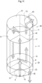
- a conventional economizer as illustrated in FIG. 17 of the present application and described in JP 3587895 B2 is configured such that a large number of water tubes are arranged in a flue 2 through which combustion exhaust gas generated by a boiler 1 flows, and water flowing within each water tube is heated by heat exchange. Further, by U-shaped tubes 4 outside the flue and providing end plates 5 outside the flue, the path of the water tubes is folded back to pass through the flue 2 again in the opposite direction, and by repeating this, the path is made longer.
- the water tubes in the flue 2 are provided with a large number of fin tubes 3 in order to improve heat absorption.
- a large number of vertical water tubes are arranged in the flue by folding back the water supply path at the upper part and the lower part of the flue, and at least lower folded back portions (U-shaped tubes 4) are provided inside the flue.
- a spray nozzle 7 for injecting blow water from the boiler 1 via a blow pipe 6 is arranged toward the water tubes in the flue, whereby the blow water is sprayed toward the water tubes and the blow water is stored in a water tank (water part 9) at the lower part of the flue so that the folded back portions are immersed in the water, and the water overflowing the water tank is drained from a drain pipe 8.
- the water within the water tubes is warmed by the water supply path (water tubes) arranged in the flue 2, so that the heat absorption efficiency of the water flowing within the water tubes is poor and warming cannot be performed as expected.
- the amount of warmed water held for example, 10 to 20 liters
- sufficient warming cannot be maintained when the amount of water supplied per hour increases.
- the present inventor has proposed an economizer ( JP 2019 054551 A ) shown in FIG. 14 to FIG. 16 of the present application as a structure capable of efficiently warming water.
- the economizer is provided with a combustion exhaust gas introduction chamber 20 facing a combustion exhaust gas introduction port 15, at a lower end position in a cylindrical water pipe 11 in which an inflow port 12 and an outflow port 13 are formed on a side surface and through which water passes, a lower connection chamber 30 partitioned from the combustion exhaust gas introduction chamber 20, a combustion exhaust gas discharge chamber 40 facing a combustion exhaust gas exhaust port 19, at an upper end position in the water pipe, and an upper annular connection chamber 50 partitioned from the combustion exhaust gas discharge chamber 40 and surrounding the combustion exhaust gas discharge chamber 40.
- first gas pipes 61 erected penetrating a lower partition wall 14 and an upper partition wall 17 along the circumference of an inner wall of the water pipe 11 so as to connect the combustion exhaust gas introduction chamber 20 and the upper annular connection chamber 50
- second gas pipes 62 erected penetrating the lower partition wall 14 and the upper partition wall 17 at inner positions of the first gas pipes 61 so as to connect the upper annular connection chamber 50 and the lower connection chamber 30
- third gas pipes 63 erected penetrating the lower partition wall 14 and the upper partition wall 17 at inner positions of the second gas pipes 62 so as to connect the lower connection chamber 30 and the combustion exhaust gas discharge chamber 40, whereby the water is warmed using the combustion exhaust gas generated by the boiler.
- the lower partition wall 14 having a disc shape is attached to a lower position in the cylindrical water pipe 11 through which the water passes, and the combustion exhaust gas introduction chamber 20 facing the combustion exhaust gas introduction port 15 formed at the lower end position of the water pipe 11 is formed.
- the lower connection chamber 30 partitioned from the combustion exhaust gas introduction chamber 20 is formed by closing a lower surface side of the lower partition wall 14 with a conical lid portion 16. Since the lower connection chamber 30 is closed with the conical lid portion 16, the lower connection chamber 30 is composed of a conical space projecting toward the combustion exhaust gas introduction chamber side.
- the upper partition wall 17 having a disc shape is attached to an upper position in the water pipe 11, and an annular partition wall 18 is attached between the upper partition wall 17 and the rear surface of the top plate of the water pipe 11, whereby the combustion exhaust gas discharge chamber 40 facing the combustion exhaust gas exhaust port 19 formed at the upper end position of the water pipe 11 and the upper annular connection chamber 50 surrounding the combustion exhaust gas discharge chamber 40 are formed.
- the water in the water pipe 11 is warmed by heat exchange at the time when the combustion exhaust gas introduced from the bottom surface side of the water pipe 11 folds back at the upper part of the water pipe 11, flows downward, folds back at the lower part of the water pipe 11, flows upward, and flows out from the upper surface side of the water pipe 11.
- the plurality of first gas pipes 61 and the plurality of second gas pipes 62 are annularly arranged in a row in the water pipe 11 with the number of pipes and the sum total of cross-sectional areas being the same, so that the number of gas pipes that can be arranged may be limited.
- the number of third gas pipes 63 that can be arranged inside the annular partition wall 18 by welding is limited in order to secure the welding work, so that the number of first gas pipes 61 and second gas pipes 62 is determined accordingly. Since the first gas pipes 61 are also arranged in a row, the arrangement density is lower than that of the second gas pipes 62. Therefore, there is a problem in such an economizer that it hindered effective warming by maximizing the number of arrangements.
- an object of the present invention is to provide an economizer having a structure capable of installing the maximum number of gas pipes in the same area to effectively warm water and facilitating inspection and cleaning.
- An economizer for warming water by combustion exhaust gas generated by a boiler according to the present invention comprises:
- combustion exhaust gas introduction chamber (A) is formed with an area where the combustion exhaust gas introduction pipe (20) is divided into three equal parts in a horizontal plane
- combustion exhaust gas discharge chamber (C) is formed with an area where the combustion exhaust gas discharge pipe (40) is divided into three equal parts in a horizontal plane, so that passages where the first gas pipes, the second gas pipes, and the third gas pipes are erected each have the same area.
- the economizer further comprises a bottom surface lid (attaching/detaching portion 21b) detachably attached to a position excluding the gas introduction port (15) provided on a lower surface side of the combustion exhaust gas introduction pipe (20), and an upper surface lid (attaching/detaching portion 41b) detachably attached to a position excluding the gas exhaust port (19) provided on an upper surface side of the combustion exhaust gas discharge pipe (40).
- Both ends of the first gas pipes (61), the second gas pipes (62), and the third gas pipes (63) can be inspected in a state in which the bottom surface lid (attaching/detaching portion 21b) and the upper surface lid (attaching/detaching portion 41b) are removed.
- the gas exhaust port (19) is provided on a side surface side of the combustion exhaust gas discharge pipe (20) to allow an upper surface of the combustion exhaust gas discharge pipe (20) to be opened by opening and closing operation of a top plate (41), so that upper ends of the first gas pipes (61), the second gas pipes (62), and the third gas pipes (63) can be inspected when the top plate is opened.
- a cleaning pipe (85) is connected to a lower surface of the lower combustion exhaust gas passage chamber (B).
- the combustion exhaust gas introduction chamber (A) and the combustion exhaust gas discharge chamber (C) are fan-shaped in a horizontal plane.
- a total of cross-sectional areas of the first gas pipes (61), a total of cross-sectional areas of the second gas pipes (62), and a total of cross-sectional areas of the third gas pipes (63) are equal to one another.
- first gas pipes (61), the second gas pipes (62), and the third gas pipes (63) are equal in number to one another.
- the inflow port (12) is formed at a lower position of the side surface of the water pipe, and the outflow port (13) is formed at an upper position of the side surface of the water pipe.
- the water pipe (11) is composed of a pressure water container.
- the plurality of gas pipes (61, 62, 63) erected for circulating the combustion exhaust gas are arranged in the water pipe (11), whereby water supplied into the water pipe is efficiently warmed around the gas pipes.
- each opening on the upper end side of the first gas pipes (61) and the second gas pipes (62) and each opening on the lower end side of the second gas pipes (62) and the third gas pipes (63) can be inspected by removing only the upper surface lid (attaching/detaching portion 41b) and the bottom surface lid (attaching/detaching portion 21b), inspection and cleaning of the inside of each gas pipe can be performed easily.
- the top plate (41) allowing the entire upper surface of the combustion exhaust gas discharge pipe (20) to be opened can be provided and the upper ends of the first gas pipes (61), the second gas pipes (62), and the third gas pipes (63) can be inspected when the top plate (41) is opened.
- the first gas pipes (61), the second gas pipes (62), and the third gas pipes (63) can be arranged in the regions (fan-shaped portions) where the water pipe (11) is divided into three parts in the horizontal plane without considering the arrangement positions of the other gas pipes, so that a large number of gas pipes can be installed in each fan-shaped portion.
- the first gas pipes, the second gas pipes, and the third gas pipes can be made the same in size.
- the warmed water can easily flow out.
- the warmed water can be brought to a temperature of 100°C or higher.
- FIG. 1 to FIG. 6 parts having the same configurations as those in FIG. 14 to FIG. 16 are denoted by the same reference signs.
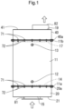
- An economizer warms water by combustion exhaust gas generated by a boiler, and as shown in FIG. 1 , three inflow ports 12 and three outflow ports 13 are formed on a side surface of a cylindrical water pipe (water container) 11.
- the inflow ports 12 are formed at lower positions on the side surface of the water pipe at 120 degree intervals
- the outflow ports 13 are formed at upper positions on the side surface of the water pipe at 120 degree intervals
- water (feedwater) supplied from the three inflow ports 12 is configured to be warmed up inside the water pipe to rise and flow out (be drained) from the three outflow ports 13.
- a disc-shaped lower partition wall 14 is attached at a lower end position in the cylindrical water pipe 11 through which the water passes, and a combustion exhaust gas introduction pipe 20 having the same diameter as the water pipe 11 is connected and fixed with flange portions (flange portion 11a and flange portion 20a) facing each other so as to cover the lower partition wall 14.
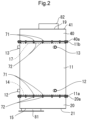
- the combustion exhaust gas introduction pipe 20 is closed by a bottom plate 21, and a combustion exhaust gas introduction port 15 is formed in the bottom plate 21 ( FIG. 1 , FIG. 2 , and FIG. 4 ).
- An introduction gas pipe 81 connected to the combustion exhaust gas introduction port 15 is vertically erected on the bottom plate 21.
- connection between the water pipe 11 and the combustion exhaust gas introduction pipe 20 is such that the flange portion 11a formed on the water pipe 11 and the flange portion 20a formed on the combustion exhaust gas introduction pipe 20 are facing each other and detachably connected and fixed by a plurality of bolts 71 and nuts 72.
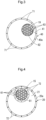
- the inside of the combustion exhaust gas introduction pipe 20 is partitioned into a combustion exhaust gas introduction chamber A facing the combustion exhaust gas introduction port 15 and a lower combustion exhaust gas passage chamber B by a vertical lower partition wall 22 ( FIG. 5 ).
- the vertical lower partition wall 22 is formed of a bent piece bent at an angle of 120 degrees at the center, so that the combustion exhaust gas introduction chamber A is partitioned to have one-third the area of the combustion exhaust gas introduction pipe 20 in a horizontal plane.
- a disc-shaped upper partition wall 17 is attached to an upper end position in the water pipe 11, and a combustion exhaust gas discharge pipe 40 having the same diameter as the water pipe 11 is connected and fixed with flange portions (flange portion 11b and flange portion 40a) facing each other so as to cover the upper partition wall 17.
- the combustion exhaust gas discharge pipe 40 is closed by a top plate 41, and a combustion exhaust gas exhaust port 19 is formed in the top plate 41 ( FIG. 1 to FIG. 3 ).
- connection between the water pipe 11 and the combustion exhaust gas discharge pipe 40 is such that the flange portion 11b formed on the water pipe 11 and the flange portion 40a formed on the combustion exhaust gas discharge pipe 40 are facing each other and detachably connected and fixed by a plurality of bolts 71 and nuts 72.
- An exhaust gas pipe 82 connected to the combustion exhaust gas exhaust port 19 is vertically erected on the top plate 41.
- the inside of the combustion exhaust gas discharge pipe 40 is partitioned into a combustion exhaust gas discharge chamber C facing the combustion exhaust gas exhaust port 19 and an upper combustion exhaust gas passage chamber D by a vertical upper partition wall 42 ( FIG. 5 ).
- the vertical upper partition wall 42 is formed of a bent piece bent at an angle of 120 degrees at the center, so that the combustion exhaust gas discharge chamber C is partitioned to have one-third the area of the combustion exhaust gas discharge pipe 40 in a horizontal plane.
- a plurality of gas pipes are arranged in the water pipe 11 in order to circulate the combustion exhaust gas.
- the gas pipes are composed of a plurality of first gas pipes 61 erected in a one-third area portion (fan shape) of the horizontal plane of the water pipe 11 so as to penetrate the lower partition wall 14 and the upper partition wall 17 and connect the combustion exhaust gas introduction chamber A and the upper combustion exhaust gas passage chamber D, a plurality of second gas pipes 62 erected in a one-third area portion (fan shape) of the horizontal plane of the water pipe 11 so as to penetrate the lower partition wall 14 and the upper partition wall 17 and connect the upper combustion exhaust gas passage chamber D and the lower combustion exhaust gas passage chamber B, and a plurality of third gas pipes 63 erected in a one-third area portion (fan shape) of the horizontal plane of the water pipe 11 so as to penetrate the lower partition wall 14 and the upper partition wall 17 and connect the lower combustion exhaust gas passage chamber B and the combustion exhaust gas discharge chamber C.
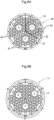
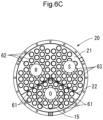
- 31 of the first gas pipes 61 are arranged in the fan-shaped column portion of the water pipe 11 and configured so as to communicate the combustion exhaust gas introduction chamber A and the upper combustion exhaust gas passage chamber D.
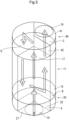
- the combustion exhaust gas introduced from the combustion exhaust gas introduction port 15 to the combustion exhaust gas introduction chamber A passes through the plurality of first gas pipes 61, moves upward (from a passage O to a passage P in FIG. 5 ), and is once guided to the upper combustion exhaust gas passage chamber D.
- the combustion exhaust gas from the upper combustion exhaust gas passage chamber D passes through the plurality of second gas pipes 62, moves downward (from a passage Q to a passage R in FIG. 5 ), and is once guided to the lower combustion exhaust gas passage chamber B.
- the combustion exhaust gas from the lower combustion exhaust gas passage chamber B passes through the plurality of third gas pipes 63, moves upward (from a passage S to a passage T in FIG. 5 ), and is discharged from the combustion exhaust gas exhaust port 19 via the combustion exhaust gas discharge chamber C.
- each group of gas pipes arranged in the fan-shaped portion in the horizontal plane can be freely arranged without being restricted by arrangement positions of the other gas pipes, so that as many gas pipes as possible can be installed in the fan-shaped area portion.
- the cross-sectional area of the gas pipes can be reduced (the gas flow path is narrowed) to increase the gas flow velocity, and indirect heating within the water pipe between the combustion exhaust gas and the water can be performed without reducing the heat transfer area by increasing the number of gas pipes.
- the water in the water pipe can be efficiently warmed.
- the first gas pipes 61, the second gas pipes 62, and the third gas pipes 63 are provided in the same number (31), and each gas pipe is also formed with the same diameter, so that the total cross-sectional area which becomes a flow path is the same. This is to reduce the resistance generated when the combustion exhaust gas moves from the first gas pipes 61 to the second gas pipes 62 and from the second gas pipes 62 to the third gas pipes 63.
- the upper end and the lower end of the water pipe 11 are configured to be connected by the flange portions, and the combustion exhaust gas introduction pipe (combustion exhaust gas introduction chamber) 20 and the combustion exhaust gas discharge pipe (combustion exhaust gas discharge chamber) 40 can be easily attached and detached to and from the water pipe 11 by the flange portions, so that each opening at both ends of the first gas pipes 61, the second gas pipes 62, and the third gas pipes 63 can be inspected from above and below.
- combustion exhaust gas introduction pipe (combustion exhaust gas introduction chamber) 20 and the combustion exhaust gas discharge pipe (combustion exhaust gas discharge chamber) 40 can be attached and detached to and from the water pipe 11 by the flange portions, a part of the bottom plate 21 of the combustion exhaust gas introduction pipe 20 and a part of the top plate 41 of the combustion exhaust gas discharge pipe 40 may be attachably and detachably formed, as shown in FIG. 7 .
- the bottom plate 21 is composed of a fixed portion 21a and an attaching/detaching portion (bottom surface lid) 21b, and the attaching/detaching portion 21b is configured to be removed in a state in which the pipe is connected to the combustion exhaust gas introduction port 15 formed in the fixed portion 21a.
- the attaching/detaching portion 21b is composed of a sealing structure that becomes a sealed state with respect to the lower combustion exhaust gas passage chamber B.
- the top plate 41 is composed of a fixed portion 41a and an attaching/detaching portion (upper surface lid) 41b, and the attaching/detaching portion 41b is configured to be removed in a state in which the pipe is connected to the combustion exhaust gas exhaust port 19 formed in the fixed portion 41a.
- the attaching/detaching portion 41b is composed of a sealing structure that becomes a sealed state with respect to the upper combustion exhaust gas passage chamber D.
- the attaching/detaching portion (bottom surface lid) 21b of the bottom plate 21 and the attaching/detaching portion (upper surface lid) 41b of the top plate 41 have a shape in which the fixed portions (21a, 41a) having a fan shape with an interior angle of 120 degrees are removed from the disc-shaped lid bodies (bottom plate 21, top plate 41).
- the structure that the attaching/detaching portions 21b, 41b can be attached and detached to and from the combustion exhaust gas introduction pipe (combustion exhaust gas introduction chamber) 20 and the combustion exhaust gas discharge pipe (combustion exhaust gas discharge chamber) 40 respectively can be realized by connection with bolts and nuts or by hinges.
- the lower ends of the second gas pipes 62 and the third gas pipes 63 can be inspected when the attaching/detaching portion 21b is removed from the combustion exhaust gas introduction pipe (combustion exhaust gas introduction chamber) 20.
- the upper ends of the first gas pipes 61 and the second gas pipes 62 can be inspected when the attaching/detaching portion 41b is removed from the combustion exhaust gas discharge pipe (combustion exhaust gas discharge chamber) 40.
- the inside of the gas pipe can be easily cleaned by light work of removing only the lightweight attaching/detaching portion 21b and attaching/detaching portion 41b in the state in which the pipe is connected to the combustion exhaust gas introduction pipe (combustion exhaust gas introduction chamber) 20 and the combustion exhaust gas discharge pipe (combustion exhaust gas discharge chamber) 40.
- FIG. 8 to FIG. 12 show another example of the embodiment of the economizer. Parts having the same configurations as those of the economizer shown in FIG. 1 to FIG. 7 are denoted by the same reference signs and detailed description thereof will be omitted, and different configurations will be described below.
- the combustion exhaust gas exhaust port 19 provided on the upper surface side in the economizer of FIG. 1 to FIG. 7 is provided on a side surface side of the combustion exhaust gas discharge pipe 40, and the top plate 41 on the upper surface of the combustion exhaust gas discharge pipe 40 is formed so as to be openable by opening and closing operation.
- the top plate 41 is composed of a sealing structure that becomes a sealed state with respect to each of the combustion exhaust gas discharge chamber C and the upper combustion exhaust gas passage chamber D.
- the entire upper surface side of the combustion exhaust gas discharge pipe 40 can be opened in a state in which the combustion exhaust gas discharge pipe (combustion exhaust gas discharge chamber) 40 is connected to the combustion exhaust gas exhaust port 19, and all of the upper ends of the first gas pipes 61, the second gas pipes 62, and the third gas pipes 63 can be inspected.
- the cleaning pipe 85 to a lower surface of the lower combustion exhaust gas passage chamber B, when water for cleaning is supplied from the upper ends of the second gas pipes 62 and the third gas pipes 63 at the time when the top plate 41 is opened, the water flowing into the lower combustion exhaust gas passage chamber B can be recovered and discarded.
- the high-temperature combustion exhaust gas introduced from the introduction gas pipe 81 via the combustion exhaust gas introduction port 15 passes through the gas pipes 61 from the combustion exhaust gas introduction chamber A, flows upward, and flows into the upper combustion exhaust gas passage chamber D.
- the combustion exhaust gas bounces off the upper combustion exhaust gas passage chamber D, passes through the second gas pipes 62, moves downward, and flows into the lower combustion exhaust gas passage chamber B.
- the combustion exhaust gas bounces off in a collision, passes through the third gas pipes 63, moves upward, flows into the combustion exhaust gas discharge chamber C, and is discharged from the exhaust gas pipe 82 via the combustion exhaust gas exhaust port 19.
- the water supplied from the inflow ports 12 of the water pipe 11 moves from bottom to top in the water pipe 11 while being warmed in contact with the circumference of the gas pipes 61, 62, 63, and flows out of the outflow ports 13.
- water supplied into the water pipe 11 can be efficiently warmed around the gas pipes by arranging, in the water pipe 11, a plurality of gas pipes (first gas pipes 61, second gas pipes 62, and third gas pipes 63) erected for circulating the combustion exhaust gas.
- the volume of the water pipe 11 can be made sufficiently large, so that the amount of water held (for example, 200 to 400 liters, and preferably 300 liters or more) can be increased. Even if the amount of water supplied per hour increases, there is an effect that a drop in water temperature due to the increased amount can be suppressed and sufficient warming (possible up to about 100°C) can be maintained.
- the amount of water held for example, 200 to 400 liters, and preferably 300 liters or more
- combustion exhaust gas is not directly guided into the water pipe 11 but only circulates through each gas pipe, so that dirt due to the combustion exhaust gas does not adhere to the inside of the water pipe 11.
- the combustion exhaust gas introduction pipe 20 and the combustion exhaust gas discharge pipe 40 are respectively connected to the upper end and the lower end of the water pipe 11 via the flange portions, so that both can be easily detached at the flange portions by removing the bolts 71 and the nuts 72, and both ends of each of the first gas pipes 61, the second gas pipes 62, and the third gas pipes 63 can be inspected to facilitate the cleaning of the inside of the gas pipes.
- both ends of each of the first gas pipes 61, the second gas pipes 62, and the third gas pipes 63 can be inspected by removing the lower surface lid 21b and the upper surface lid 41b to facilitate the cleaning of the inside of the gas pipes.
- the entire upper surface side of the combustion exhaust gas discharge pipe 40 can be opened by opening and closing of the top plate 41 by providing the combustion exhaust gas exhaust port 19 on the side surface side of the combustion exhaust gas discharge pipe 40, and all of the upper ends of the first gas pipes 61, the second gas pipes 62, and the third gas pipes 63 can be inspected.
- the water pipe 11 of the foregoing economizer is composed of a water container in which atmospheric pressure is applied to the water surface of the water held and the water warmed in the water pipe flows out (is drained) from the outflow ports 13.
- the water pipe 11 may be composed of a pressure water container in which water is stored at a constant pressure different from the atmospheric pressure by supplying water by pump pressure and holding the water level by solenoid valve control.
- the warmed water can be raised to about 150°C, which is 100°C or higher.
- a boiler 102 feeds the combustion gas from a blower 103 to the water supplied from the economizer 101 thereby discharging steam, and feeds the combustion exhaust gas from the combustion exhaust gas introduction pipe 20 of the economizer 101 and warms the water supplied to the economizer 101 of the foregoing structure.
- the water having an average supply water temperature of 15 degrees is pressurized (for example, 0.98 MPa, 1.57 MPa, 2.94 MPa) via a pump (not shown) and supplied into the pressure container (water tank) 11. Since the supplied water is pressurized, the water is warmed up to about 120 degrees in the water tank 11 and discharged from the outflow ports 13.
- the warmed water is supplied to the boiler 102 side, and then steam is generated from the warmed water of 120 degrees in the boiler. Since the steam is generated from the warmed water of 120 degrees, the combustion gas supplied from the blower 103 can be efficiently used and an energy saving effect can be achieved.
Landscapes
- Engineering & Computer Science (AREA)
- Physics & Mathematics (AREA)
- Thermal Sciences (AREA)
- Mechanical Engineering (AREA)
- General Engineering & Computer Science (AREA)
- Combustion & Propulsion (AREA)
- Chemical & Material Sciences (AREA)
- Life Sciences & Earth Sciences (AREA)
- Sustainable Development (AREA)
- Sustainable Energy (AREA)
- Incineration Of Waste (AREA)
- Heat-Exchange Devices With Radiators And Conduit Assemblies (AREA)
- Chimneys And Flues (AREA)
- Air Supply (AREA)
Claims (8)
- Economizer zum Erwärmen von Wasser durch Verbrennungsabgase, die von einem Kessel erzeugt werden, umfassend:ein zylindrisches Wasserrohr (11), in welchem eine Einströmöffnung (12) und eine Ausströmöffnung (13) an einer Seitenfläche gebildet sind und durch welches das Wasser strömt;ein Verbrennungsabgaseinleitungsrohr (20), das über eine Trennwand mit einer unteren Endposition des Wasserrohrs (11) verbunden ist;ein Verbrennungsabgasauslassrohr (40), das über eine Trennwand mit einer oberen Endposition des Wasserrohrs (11) verbunden ist;wobei das Innere des Verbrennungsabgaseinleitungsrohrs (20) in eine Verbrennungsabgaseinleitungskammer (A), die einer Gaseinleitungsöffnung (15) zugewandt ist, und eine untere Verbrennungsabgasdurchgangskammer (B) unterteilt ist, und das Innere des Verbrennungsabgasauslassrohrs (40) in eine Verbrennungsabgasauslasskammer (C), die einer Gasablassöffnung (19) zugewandt ist, und eine obere Verbrennungsabgasdurchgangskammer (D) unterteilt ist,eine Vielzahl von ersten Gasrohren (61), die in dem Wasserrohr (11) angeordnet sind und die Trennwände (14, 17) durchdringen, um eine Verbindung zwischen der Verbrennungsabgaseinleitungskammer (A) und der oberen Verbrennungsabgasdurchgangskammer (D) herzustellen;eine Vielzahl von zweiten Gasrohren (62), die in dem Wasserrohr (11) angeordnet sind und die Trennwände (14, 17) durchdringen, um eine Verbindung zwischen der oberen Verbrennungsabgasdurchgangskammer (D) und der unteren Verbrennungsabgasdurchgangskammer (B) herzustellen; undeine Vielzahl von dritten Gasrohren (63), die in dem Wasserrohr (11) angeordnet sind und die Trennwände (14, 17) durchdringen, um eine Verbindung zwischen der unteren Verbrennungsabgasdurchgangskammer (B) und der Verbrennungsabgasauslasskammer (C) herzustellen,wobei die Verbrennungsabgaseinleitungskammer (A) mit einem Bereich ausgebildet ist, in dem das Verbrennungsabgaseinleitungsrohr (20) in einer horizontalen Ebene in drei gleiche Teile unterteilt ist, und die Verbrennungsabgasauslasskammer (C) mit einem Bereich ausgebildet ist, in dem das Verbrennungsabgasauslassrohr (40) in einer horizontalen Ebene in drei gleiche Teile unterteilt ist, sodass Durchgänge, in denen die ersten Gasrohre (61), die zweiten Gasrohre (62) und die dritten Gasrohre (63) gebildet sind, jeweils die gleiche Fläche aufweisen, wobeiein unterer Oberflächendeckel (21b), der abnehmbar an einer Position mit Ausnahme der Gaseinleitungsöffnung (15) befestigt ist, die an einer unteren Oberflächenseite des Verbrennungsabgaseinleitungsrohrs (20) vorgesehen ist, und ein oberer Oberflächendeckel (41b), der abnehmbar an einer Position mit Ausnahme der Gasablassöffnung (19) befestigt ist, die an einer oberen Oberflächenseite des Verbrennungsabgasauslassrohrs (40) vorgesehen ist, vorgesehen sind, undbeide Enden der ersten Gasrohre (61), der zweiten Gasrohre (62) und der dritten Gasrohre (63) in einem Zustand inspiziert werden können, in dem der untere Oberflächendeckel (21b) und der obere Oberflächendeckel (41b) entfernt sind.
- Economizer zum Erwärmen von Wasser durch Verbrennungsabgase, die von einem Kessel erzeugt werden, umfassend:ein zylindrisches Wasserrohr (11), in welchem eine Einströmöffnung (12) und eine Ausströmöffnung (13) an einer Seitenfläche ausgebildet sind und durch welches das Wasser strömt;ein Verbrennungsabgaseinleitungsrohr (20), das über eine Trennwand mit einer unteren Endposition des Wasserrohrs (11) verbunden ist;ein Verbrennungsabgasauslassrohr (40), das über eine Trennwand mit einer oberen Endposition des Wasserrohrs (11) verbunden ist;wobei das Innere des Verbrennungsabgaseinleitungsrohrs (20) in eine Verbrennungsabgaseinleitungskammer (A), die einer Gaseinleitungsöffnung (15) zugewandt ist, und eine untere Verbrennungsabgasdurchgangskammer (B) unterteilt ist, und das Innere des Verbrennungsabgasauslassrohrs (40) in eine Verbrennungsabgasauslasskammer (C), die einer Gasablassöffnung (19) zugewandt ist, und eine obere Verbrennungsabgasdurchgangskammer (D) unterteilt ist,eine Vielzahl von ersten Gasrohren (61), die in dem Wasserrohr (11) angeordnet sind und die Trennwände (14, 17) durchdringen, um eine Verbindung zwischen der Verbrennungsabgaseinleitungskammer (A) und der oberen Verbrennungsabgasdurchgangskammer (D) herzustellen;eine Vielzahl von zweiten Gasrohren (62), die in dem Wasserrohr (11) angeordnet sind und die Trennwände (14, 17) durchdringen, um eine Verbindung zwischen der oberen Verbrennungsabgasdurchgangskammer (D) und der unteren Verbrennungsabgasdurchgangskammer (B) herzustellen; undeine Vielzahl von dritten Gasrohren (63), die in dem Wasserrohr (11) angeordnet sind und die Trennwände (14, 17) durchdringen, um eine Verbindung zwischen der unteren Verbrennungsabgasdurchgangskammer (B) und der Verbrennungsabgasauslasskammer (C) herzustellen,wobei die Verbrennungsabgaseinleitungskammer (A) mit einem Bereich ausgebildet ist, in dem das Verbrennungsabgaseinleitungsrohr (20) in einer horizontalen Ebene in drei gleiche Teile unterteilt ist, und die Verbrennungsabgasauslasskammer (C) mit einem Bereich ausgebildet ist, in dem das Verbrennungsabgasauslassrohr (40) in einer horizontalen Ebene in drei gleiche Teile unterteilt ist, sodass Durchgänge, in denen die ersten Gasrohre (61), die zweiten Gasrohre (62) und die dritten Gasrohre (63) gebildet sind, jeweils die gleiche Fläche haben, wobeidie Gasablassöffnung (19) an einer Seitenoberflächenseite des Verbrennungsabgasauslassrohrs (40) vorgesehen ist, um zu ermöglichen, dass eine obere Oberfläche des Verbrennungsabgasauslassrohrs (40) durch Öffnen und Schließen einer oberen Platte (41) geöffnet werden kann, sodass die oberen Enden der ersten Gasrohre (61), der zweiten Gasrohre (62) und der dritten Gasrohre (63) inspiziert werden können, wenn die obere Platte (41) geöffnet ist.
- Economizer nach Anspruch 2, wobei ein Reinigungsrohr (85) mit einer unteren Fläche der unteren Verbrennungsabgasdurchgangskammer (B) verbunden ist.
- Economizer nach Anspruch 1 oder 2, wobei die Verbrennungsabgaseinleitungskammer (A) und die Verbrennungsabgasauslasskammer (C) in einer horizontalen Ebene fächerförmig ausgebildet sind.
- Economizer nach Anspruch 1 oder 2, wobei eine Summe der Querschnittsflächen der ersten Gasrohre (61), eine Summe der Querschnittsflächen der zweiten Gasrohre (62) und eine Summe der Querschnittsflächen der dritten Gasrohre (63) einander gleich sind.
- Economizer nach Anspruch 5, wobei die ersten Gasrohre (61), die zweiten Gasrohre (62) und die dritten Gasrohre (63) in ihrer Anzahl gleich sind.
- Economizer nach Anspruch 1 oder 2, wobei die Einströmöffnung (12) an einer unteren Position der Seitenfläche des Wasserrohrs (11) ausgebildet ist und die Ausströmöffnung (13) an einer oberen Position der Seitenfläche des Wasserrohrs (11) ausgebildet ist.
- Economizer nach einem der Ansprüche 1 bis 7, wobei das Wasserrohr (11) aus einem Druckwasserbehälter besteht.
Applications Claiming Priority (2)
| Application Number | Priority Date | Filing Date | Title |
|---|---|---|---|
| JP2019081003 | 2019-04-22 | ||
| PCT/JP2019/020532 WO2020217545A1 (ja) | 2019-04-22 | 2019-05-23 | エコノマイザー |
Publications (4)
| Publication Number | Publication Date |
|---|---|
| EP3961095A1 EP3961095A1 (de) | 2022-03-02 |
| EP3961095A4 EP3961095A4 (de) | 2023-01-18 |
| EP3961095C0 EP3961095C0 (de) | 2023-09-20 |
| EP3961095B1 true EP3961095B1 (de) | 2023-09-20 |
Family
ID=72942348
Family Applications (1)
| Application Number | Title | Priority Date | Filing Date |
|---|---|---|---|
| EP19926723.8A Active EP3961095B1 (de) | 2019-04-22 | 2019-05-23 | Economizer |
Country Status (8)
| Country | Link |
|---|---|
| US (1) | US11732885B2 (de) |
| EP (1) | EP3961095B1 (de) |
| JP (1) | JP7128350B2 (de) |
| KR (1) | KR102591349B1 (de) |
| CN (1) | CN113767251B (de) |
| ES (1) | ES2960965T3 (de) |
| PL (1) | PL3961095T3 (de) |
| WO (1) | WO2020217545A1 (de) |
Family Cites Families (25)
| Publication number | Priority date | Publication date | Assignee | Title |
|---|---|---|---|---|
| US1746564A (en) * | 1927-12-05 | 1930-02-11 | Leader Iron Works | Heat economizer |
| US1948550A (en) * | 1932-07-23 | 1934-02-27 | Joseph T Voorheis | Oil heater |
| US2416273A (en) * | 1944-04-29 | 1947-02-18 | Petro Chem Process Company Inc | Waste heat economizer |
| GB937301A (en) * | 1958-10-18 | 1963-09-18 | Holmes & Co Ltd W C | Improvements in or relating to heat exchangers |
| DE1576794A1 (de) * | 1967-07-07 | 1970-05-06 | Buss Ag | Mehrzugdampfkessel |
| JPS587895B2 (ja) | 1974-12-25 | 1983-02-12 | カブシキガイシヤ ヨウエイセイサクシヨ | ホウネツボウシヨウダンパ−ツキチヨトウシキキユウトウキ |
| US4138969A (en) * | 1977-07-08 | 1979-02-13 | Applied Engineering Co. | Heat exchanger and economizer |
| JPS58154997U (ja) * | 1982-04-10 | 1983-10-17 | 日本ビクター株式会社 | 電子楽器のエンベロ−プ回路 |
| JPS6066904U (ja) * | 1983-10-07 | 1985-05-13 | 日本フアースト工業株式会社 | 貯槽型排熱回収用熱交換器 |
| GB2218787B (en) * | 1988-05-20 | 1992-06-10 | Northern Eng Ind | Boilers |
| JP3587895B2 (ja) | 1994-12-07 | 2004-11-10 | 株式会社サムソン | エコノマイザー |
| KR100494185B1 (ko) * | 2003-04-22 | 2005-06-10 | 박용묵 | 실리콘 카바이드 튜브가 구비된 열교환기 |
| CN2795676Y (zh) * | 2005-05-10 | 2006-07-12 | 蒋金良 | 锅炉烟道节能器 |
| KR100818414B1 (ko) * | 2007-04-17 | 2008-04-02 | 박창덕 | 연관식 증기 보일러 |
| KR101274091B1 (ko) * | 2011-06-27 | 2013-06-12 | 강림중공업 주식회사 | 배기가스 챔버 분리형 폐열보일러 |
| WO2013128484A1 (ja) * | 2012-02-28 | 2013-09-06 | 株式会社大阪ボイラー製作所 | 煙管式コンポジットボイラ及び該ボイラを備える廃熱回収システム |
| US10197266B2 (en) * | 2014-06-12 | 2019-02-05 | Thermodesign, Inc. | Boiler system comprising an integrated economizer |
| JP6479434B2 (ja) * | 2014-11-20 | 2019-03-06 | 三菱重工業株式会社 | 煙管式ボイラ及び排熱回収システム |
| JP6472267B2 (ja) * | 2015-02-20 | 2019-02-20 | 三菱重工業株式会社 | エコノマイザ、コンポジットボイラ、及び使用方法 |
| CN204718131U (zh) * | 2015-05-14 | 2015-10-21 | 天津恩光科技有限公司 | 锅炉节能器 |
| US20170211845A1 (en) * | 2016-01-25 | 2017-07-27 | Hamilton Engineering, Inc. | Device for dispensing a heated fluid |
| CN105823210A (zh) * | 2016-04-26 | 2016-08-03 | 天津中海盛世新能源科技有限公司 | 一种烟气折弯循环式多水套节能采暖炉 |
| CN207455895U (zh) * | 2017-07-25 | 2018-06-05 | 刘作臣 | 一种水加热节能型锅炉 |
| JP2019054551A (ja) | 2018-12-20 | 2019-04-04 | ソニー株式会社 | 情報処理装置、情報処理方法および情報処理プログラム |
| JP3222032U (ja) | 2019-04-23 | 2019-07-04 | 猪野 貴行 | エコノマイザー |
-
2019
- 2019-05-23 US US17/602,188 patent/US11732885B2/en active Active
- 2019-05-23 ES ES19926723T patent/ES2960965T3/es active Active
- 2019-05-23 KR KR1020217033000A patent/KR102591349B1/ko active Active
- 2019-05-23 JP JP2021515768A patent/JP7128350B2/ja active Active
- 2019-05-23 CN CN201980095676.4A patent/CN113767251B/zh active Active
- 2019-05-23 PL PL19926723.8T patent/PL3961095T3/pl unknown
- 2019-05-23 WO PCT/JP2019/020532 patent/WO2020217545A1/ja not_active Ceased
- 2019-05-23 EP EP19926723.8A patent/EP3961095B1/de active Active
Also Published As
| Publication number | Publication date |
|---|---|
| US20220205631A1 (en) | 2022-06-30 |
| PL3961095T3 (pl) | 2024-01-29 |
| JPWO2020217545A1 (de) | 2020-10-29 |
| US11732885B2 (en) | 2023-08-22 |
| KR20210137180A (ko) | 2021-11-17 |
| EP3961095C0 (de) | 2023-09-20 |
| JP7128350B2 (ja) | 2022-08-30 |
| CN113767251A (zh) | 2021-12-07 |
| EP3961095A1 (de) | 2022-03-02 |
| WO2020217545A1 (ja) | 2020-10-29 |
| CN113767251B (zh) | 2023-06-02 |
| KR102591349B1 (ko) | 2023-10-20 |
| EP3961095A4 (de) | 2023-01-18 |
| ES2960965T3 (es) | 2024-03-07 |
Similar Documents
| Publication | Publication Date | Title |
|---|---|---|
| JP6334809B2 (ja) | 複数の発生源のための排気ガス洗浄システム | |
| KR910002126B1 (ko) | 슬러지 란스 완드 | |
| US11732885B2 (en) | Economizer | |
| US10859258B2 (en) | Spray nozzle and deaerator | |
| EP3414511B1 (de) | Reinigung der rohrböden von wärmetauschern | |
| JP3222032U (ja) | エコノマイザー | |
| CN216204300U (zh) | 一种便于清洗水垢的改进型热水器 | |
| CN209147780U (zh) | 一种双管板u形壳体高温换热器 | |
| CN214537476U (zh) | 一种冷却塔用冷却器 | |
| JP3221900U (ja) | エコノマイザー | |
| JPWO2020217545A5 (de) | ||
| CN103591691B (zh) | 一种燃气热水器的换热装置 | |
| CN215832528U (zh) | 换热单元、烟气余热回收交换器 | |
| JP7369557B2 (ja) | エコノマイザー | |
| JP3223058U (ja) | エコノマイザー | |
| JP7201497B2 (ja) | エコノマイザー | |
| JP7646296B2 (ja) | ボイラの火炉壁構造及びボイラの化学洗浄方法 | |
| CN215864767U (zh) | 一种低温余热发电换热装置 | |
| RU72303U1 (ru) | Парогенератор со свинцовым теплоносителем или его сплавами | |
| CN213133214U (zh) | 一种尼龙反应器喷淋塔 | |
| CN223649756U (zh) | 一种内折流式冷流道真空热管及由其组成的换热器 | |
| KR20100092673A (ko) | 열교환기 | |
| CN108916001A (zh) | 一种压缩机换热器 | |
| KR101312697B1 (ko) | 수관식 보일러 | |
| CN213687280U (zh) | 一种新型燃油锅炉 |
Legal Events
| Date | Code | Title | Description |
|---|---|---|---|
| STAA | Information on the status of an ep patent application or granted ep patent |
Free format text: STATUS: THE INTERNATIONAL PUBLICATION HAS BEEN MADE |
|
| PUAI | Public reference made under article 153(3) epc to a published international application that has entered the european phase |
Free format text: ORIGINAL CODE: 0009012 |
|
| STAA | Information on the status of an ep patent application or granted ep patent |
Free format text: STATUS: REQUEST FOR EXAMINATION WAS MADE |
|
| 17P | Request for examination filed |
Effective date: 20211001 |
|
| AK | Designated contracting states |
Kind code of ref document: A1 Designated state(s): AL AT BE BG CH CY CZ DE DK EE ES FI FR GB GR HR HU IE IS IT LI LT LU LV MC MK MT NL NO PL PT RO RS SE SI SK SM TR |
|
| DAV | Request for validation of the european patent (deleted) | ||
| DAX | Request for extension of the european patent (deleted) | ||
| A4 | Supplementary search report drawn up and despatched |
Effective date: 20221219 |
|
| RIC1 | Information provided on ipc code assigned before grant |
Ipc: F22D 1/24 20060101AFI20221213BHEP |
|
| GRAP | Despatch of communication of intention to grant a patent |
Free format text: ORIGINAL CODE: EPIDOSNIGR1 |
|
| STAA | Information on the status of an ep patent application or granted ep patent |
Free format text: STATUS: GRANT OF PATENT IS INTENDED |
|
| INTG | Intention to grant announced |
Effective date: 20230426 |
|
| GRAS | Grant fee paid |
Free format text: ORIGINAL CODE: EPIDOSNIGR3 |
|
| GRAA | (expected) grant |
Free format text: ORIGINAL CODE: 0009210 |
|
| STAA | Information on the status of an ep patent application or granted ep patent |
Free format text: STATUS: THE PATENT HAS BEEN GRANTED |
|
| AK | Designated contracting states |
Kind code of ref document: B1 Designated state(s): AL AT BE BG CH CY CZ DE DK EE ES FI FR GB GR HR HU IE IS IT LI LT LU LV MC MK MT NL NO PL PT RO RS SE SI SK SM TR |
|
| REG | Reference to a national code |
Ref country code: GB Ref legal event code: FG4D |
|
| REG | Reference to a national code |
Ref country code: CH Ref legal event code: EP |
|
| REG | Reference to a national code |
Ref country code: IE Ref legal event code: FG4D |
|
| REG | Reference to a national code |
Ref country code: DE Ref legal event code: R096 Ref document number: 602019038015 Country of ref document: DE |
|
| U01 | Request for unitary effect filed |
Effective date: 20230920 |
|
| U07 | Unitary effect registered |
Designated state(s): AT BE BG DE DK EE FI FR IT LT LU LV MT NL PT SE SI Effective date: 20230926 |
|
| PG25 | Lapsed in a contracting state [announced via postgrant information from national office to epo] |
Ref country code: GR Free format text: LAPSE BECAUSE OF FAILURE TO SUBMIT A TRANSLATION OF THE DESCRIPTION OR TO PAY THE FEE WITHIN THE PRESCRIBED TIME-LIMIT Effective date: 20231221 |
|
| PG25 | Lapsed in a contracting state [announced via postgrant information from national office to epo] |
Ref country code: RS Free format text: LAPSE BECAUSE OF FAILURE TO SUBMIT A TRANSLATION OF THE DESCRIPTION OR TO PAY THE FEE WITHIN THE PRESCRIBED TIME-LIMIT Effective date: 20230920 Ref country code: NO Free format text: LAPSE BECAUSE OF FAILURE TO SUBMIT A TRANSLATION OF THE DESCRIPTION OR TO PAY THE FEE WITHIN THE PRESCRIBED TIME-LIMIT Effective date: 20231220 Ref country code: HR Free format text: LAPSE BECAUSE OF FAILURE TO SUBMIT A TRANSLATION OF THE DESCRIPTION OR TO PAY THE FEE WITHIN THE PRESCRIBED TIME-LIMIT Effective date: 20230920 Ref country code: GR Free format text: LAPSE BECAUSE OF FAILURE TO SUBMIT A TRANSLATION OF THE DESCRIPTION OR TO PAY THE FEE WITHIN THE PRESCRIBED TIME-LIMIT Effective date: 20231221 |
|
| REG | Reference to a national code |
Ref country code: ES Ref legal event code: FG2A Ref document number: 2960965 Country of ref document: ES Kind code of ref document: T3 Effective date: 20240307 |
|
| PG25 | Lapsed in a contracting state [announced via postgrant information from national office to epo] |
Ref country code: IS Free format text: LAPSE BECAUSE OF FAILURE TO SUBMIT A TRANSLATION OF THE DESCRIPTION OR TO PAY THE FEE WITHIN THE PRESCRIBED TIME-LIMIT Effective date: 20240120 |
|
| PG25 | Lapsed in a contracting state [announced via postgrant information from national office to epo] |
Ref country code: SM Free format text: LAPSE BECAUSE OF FAILURE TO SUBMIT A TRANSLATION OF THE DESCRIPTION OR TO PAY THE FEE WITHIN THE PRESCRIBED TIME-LIMIT Effective date: 20230920 Ref country code: RO Free format text: LAPSE BECAUSE OF FAILURE TO SUBMIT A TRANSLATION OF THE DESCRIPTION OR TO PAY THE FEE WITHIN THE PRESCRIBED TIME-LIMIT Effective date: 20230920 Ref country code: IS Free format text: LAPSE BECAUSE OF FAILURE TO SUBMIT A TRANSLATION OF THE DESCRIPTION OR TO PAY THE FEE WITHIN THE PRESCRIBED TIME-LIMIT Effective date: 20240120 Ref country code: CZ Free format text: LAPSE BECAUSE OF FAILURE TO SUBMIT A TRANSLATION OF THE DESCRIPTION OR TO PAY THE FEE WITHIN THE PRESCRIBED TIME-LIMIT Effective date: 20230920 Ref country code: SK Free format text: LAPSE BECAUSE OF FAILURE TO SUBMIT A TRANSLATION OF THE DESCRIPTION OR TO PAY THE FEE WITHIN THE PRESCRIBED TIME-LIMIT Effective date: 20230920 |
|
| REG | Reference to a national code |
Ref country code: DE Ref legal event code: R097 Ref document number: 602019038015 Country of ref document: DE |
|
| U20 | Renewal fee for the european patent with unitary effect paid |
Year of fee payment: 6 Effective date: 20240527 |
|
| PLBE | No opposition filed within time limit |
Free format text: ORIGINAL CODE: 0009261 |
|
| STAA | Information on the status of an ep patent application or granted ep patent |
Free format text: STATUS: NO OPPOSITION FILED WITHIN TIME LIMIT |
|
| 26N | No opposition filed |
Effective date: 20240621 |
|
| REG | Reference to a national code |
Ref country code: CH Ref legal event code: PL |
|
| PG25 | Lapsed in a contracting state [announced via postgrant information from national office to epo] |
Ref country code: MC Free format text: LAPSE BECAUSE OF FAILURE TO SUBMIT A TRANSLATION OF THE DESCRIPTION OR TO PAY THE FEE WITHIN THE PRESCRIBED TIME-LIMIT Effective date: 20230920 |
|
| PG25 | Lapsed in a contracting state [announced via postgrant information from national office to epo] |
Ref country code: MC Free format text: LAPSE BECAUSE OF FAILURE TO SUBMIT A TRANSLATION OF THE DESCRIPTION OR TO PAY THE FEE WITHIN THE PRESCRIBED TIME-LIMIT Effective date: 20230920 Ref country code: CH Free format text: LAPSE BECAUSE OF NON-PAYMENT OF DUE FEES Effective date: 20240531 |
|
| PG25 | Lapsed in a contracting state [announced via postgrant information from national office to epo] |
Ref country code: IE Free format text: LAPSE BECAUSE OF NON-PAYMENT OF DUE FEES Effective date: 20240523 |
|
| U20 | Renewal fee for the european patent with unitary effect paid |
Year of fee payment: 7 Effective date: 20250519 |
|
| PGFP | Annual fee paid to national office [announced via postgrant information from national office to epo] |
Ref country code: PL Payment date: 20250502 Year of fee payment: 7 |
|
| PGFP | Annual fee paid to national office [announced via postgrant information from national office to epo] |
Ref country code: GB Payment date: 20250522 Year of fee payment: 7 Ref country code: ES Payment date: 20250603 Year of fee payment: 7 |
|
| PG25 | Lapsed in a contracting state [announced via postgrant information from national office to epo] |
Ref country code: CY Free format text: LAPSE BECAUSE OF FAILURE TO SUBMIT A TRANSLATION OF THE DESCRIPTION OR TO PAY THE FEE WITHIN THE PRESCRIBED TIME-LIMIT; INVALID AB INITIO Effective date: 20190523 |
|
| PG25 | Lapsed in a contracting state [announced via postgrant information from national office to epo] |
Ref country code: HU Free format text: LAPSE BECAUSE OF FAILURE TO SUBMIT A TRANSLATION OF THE DESCRIPTION OR TO PAY THE FEE WITHIN THE PRESCRIBED TIME-LIMIT; INVALID AB INITIO Effective date: 20190523 |