EP3960514A1 - Modularer übertragungsmechanismus für hybridleistungssystem und hybridleistungssystem - Google Patents
Modularer übertragungsmechanismus für hybridleistungssystem und hybridleistungssystem Download PDFInfo
- Publication number
- EP3960514A1 EP3960514A1 EP19926546.3A EP19926546A EP3960514A1 EP 3960514 A1 EP3960514 A1 EP 3960514A1 EP 19926546 A EP19926546 A EP 19926546A EP 3960514 A1 EP3960514 A1 EP 3960514A1
- Authority
- EP
- European Patent Office
- Prior art keywords
- rotor
- axial
- transmission mechanism
- radial
- output shaft
- Prior art date
- Legal status (The legal status is an assumption and is not a legal conclusion. Google has not performed a legal analysis and makes no representation as to the accuracy of the status listed.)
- Withdrawn
Links
Images


Classifications
-
- B—PERFORMING OPERATIONS; TRANSPORTING
- B60—VEHICLES IN GENERAL
- B60K—ARRANGEMENT OR MOUNTING OF PROPULSION UNITS OR OF TRANSMISSIONS IN VEHICLES; ARRANGEMENT OR MOUNTING OF PLURAL DIVERSE PRIME-MOVERS IN VEHICLES; AUXILIARY DRIVES FOR VEHICLES; INSTRUMENTATION OR DASHBOARDS FOR VEHICLES; ARRANGEMENTS IN CONNECTION WITH COOLING, AIR INTAKE, GAS EXHAUST OR FUEL SUPPLY OF PROPULSION UNITS IN VEHICLES
- B60K6/00—Arrangement or mounting of plural diverse prime-movers for mutual or common propulsion, e.g. hybrid propulsion systems comprising electric motors and internal combustion engines
- B60K6/20—Arrangement or mounting of plural diverse prime-movers for mutual or common propulsion, e.g. hybrid propulsion systems comprising electric motors and internal combustion engines the prime-movers consisting of electric motors and internal combustion engines, e.g. HEVs
- B60K6/22—Arrangement or mounting of plural diverse prime-movers for mutual or common propulsion, e.g. hybrid propulsion systems comprising electric motors and internal combustion engines the prime-movers consisting of electric motors and internal combustion engines, e.g. HEVs characterised by apparatus, components or means specially adapted for HEVs
- B60K6/38—Arrangement or mounting of plural diverse prime-movers for mutual or common propulsion, e.g. hybrid propulsion systems comprising electric motors and internal combustion engines the prime-movers consisting of electric motors and internal combustion engines, e.g. HEVs characterised by apparatus, components or means specially adapted for HEVs characterised by the driveline clutches
- B60K6/387—Actuated clutches, i.e. clutches engaged or disengaged by electric, hydraulic or mechanical actuating means
-
- B—PERFORMING OPERATIONS; TRANSPORTING
- B60—VEHICLES IN GENERAL
- B60K—ARRANGEMENT OR MOUNTING OF PROPULSION UNITS OR OF TRANSMISSIONS IN VEHICLES; ARRANGEMENT OR MOUNTING OF PLURAL DIVERSE PRIME-MOVERS IN VEHICLES; AUXILIARY DRIVES FOR VEHICLES; INSTRUMENTATION OR DASHBOARDS FOR VEHICLES; ARRANGEMENTS IN CONNECTION WITH COOLING, AIR INTAKE, GAS EXHAUST OR FUEL SUPPLY OF PROPULSION UNITS IN VEHICLES
- B60K6/00—Arrangement or mounting of plural diverse prime-movers for mutual or common propulsion, e.g. hybrid propulsion systems comprising electric motors and internal combustion engines
- B60K6/20—Arrangement or mounting of plural diverse prime-movers for mutual or common propulsion, e.g. hybrid propulsion systems comprising electric motors and internal combustion engines the prime-movers consisting of electric motors and internal combustion engines, e.g. HEVs
- B60K6/22—Arrangement or mounting of plural diverse prime-movers for mutual or common propulsion, e.g. hybrid propulsion systems comprising electric motors and internal combustion engines the prime-movers consisting of electric motors and internal combustion engines, e.g. HEVs characterised by apparatus, components or means specially adapted for HEVs
- B60K6/26—Arrangement or mounting of plural diverse prime-movers for mutual or common propulsion, e.g. hybrid propulsion systems comprising electric motors and internal combustion engines the prime-movers consisting of electric motors and internal combustion engines, e.g. HEVs characterised by apparatus, components or means specially adapted for HEVs characterised by the motors or the generators
-
- B—PERFORMING OPERATIONS; TRANSPORTING
- B60—VEHICLES IN GENERAL
- B60K—ARRANGEMENT OR MOUNTING OF PROPULSION UNITS OR OF TRANSMISSIONS IN VEHICLES; ARRANGEMENT OR MOUNTING OF PLURAL DIVERSE PRIME-MOVERS IN VEHICLES; AUXILIARY DRIVES FOR VEHICLES; INSTRUMENTATION OR DASHBOARDS FOR VEHICLES; ARRANGEMENTS IN CONNECTION WITH COOLING, AIR INTAKE, GAS EXHAUST OR FUEL SUPPLY OF PROPULSION UNITS IN VEHICLES
- B60K6/00—Arrangement or mounting of plural diverse prime-movers for mutual or common propulsion, e.g. hybrid propulsion systems comprising electric motors and internal combustion engines
- B60K6/20—Arrangement or mounting of plural diverse prime-movers for mutual or common propulsion, e.g. hybrid propulsion systems comprising electric motors and internal combustion engines the prime-movers consisting of electric motors and internal combustion engines, e.g. HEVs
- B60K6/22—Arrangement or mounting of plural diverse prime-movers for mutual or common propulsion, e.g. hybrid propulsion systems comprising electric motors and internal combustion engines the prime-movers consisting of electric motors and internal combustion engines, e.g. HEVs characterised by apparatus, components or means specially adapted for HEVs
- B60K6/36—Arrangement or mounting of plural diverse prime-movers for mutual or common propulsion, e.g. hybrid propulsion systems comprising electric motors and internal combustion engines the prime-movers consisting of electric motors and internal combustion engines, e.g. HEVs characterised by apparatus, components or means specially adapted for HEVs characterised by the transmission gearings
-
- B—PERFORMING OPERATIONS; TRANSPORTING
- B60—VEHICLES IN GENERAL
- B60K—ARRANGEMENT OR MOUNTING OF PROPULSION UNITS OR OF TRANSMISSIONS IN VEHICLES; ARRANGEMENT OR MOUNTING OF PLURAL DIVERSE PRIME-MOVERS IN VEHICLES; AUXILIARY DRIVES FOR VEHICLES; INSTRUMENTATION OR DASHBOARDS FOR VEHICLES; ARRANGEMENTS IN CONNECTION WITH COOLING, AIR INTAKE, GAS EXHAUST OR FUEL SUPPLY OF PROPULSION UNITS IN VEHICLES
- B60K6/00—Arrangement or mounting of plural diverse prime-movers for mutual or common propulsion, e.g. hybrid propulsion systems comprising electric motors and internal combustion engines
- B60K6/20—Arrangement or mounting of plural diverse prime-movers for mutual or common propulsion, e.g. hybrid propulsion systems comprising electric motors and internal combustion engines the prime-movers consisting of electric motors and internal combustion engines, e.g. HEVs
- B60K6/22—Arrangement or mounting of plural diverse prime-movers for mutual or common propulsion, e.g. hybrid propulsion systems comprising electric motors and internal combustion engines the prime-movers consisting of electric motors and internal combustion engines, e.g. HEVs characterised by apparatus, components or means specially adapted for HEVs
- B60K6/40—Arrangement or mounting of plural diverse prime-movers for mutual or common propulsion, e.g. hybrid propulsion systems comprising electric motors and internal combustion engines the prime-movers consisting of electric motors and internal combustion engines, e.g. HEVs characterised by apparatus, components or means specially adapted for HEVs characterised by the assembly or relative disposition of components
-
- B—PERFORMING OPERATIONS; TRANSPORTING
- B60—VEHICLES IN GENERAL
- B60K—ARRANGEMENT OR MOUNTING OF PROPULSION UNITS OR OF TRANSMISSIONS IN VEHICLES; ARRANGEMENT OR MOUNTING OF PLURAL DIVERSE PRIME-MOVERS IN VEHICLES; AUXILIARY DRIVES FOR VEHICLES; INSTRUMENTATION OR DASHBOARDS FOR VEHICLES; ARRANGEMENTS IN CONNECTION WITH COOLING, AIR INTAKE, GAS EXHAUST OR FUEL SUPPLY OF PROPULSION UNITS IN VEHICLES
- B60K6/00—Arrangement or mounting of plural diverse prime-movers for mutual or common propulsion, e.g. hybrid propulsion systems comprising electric motors and internal combustion engines
- B60K6/20—Arrangement or mounting of plural diverse prime-movers for mutual or common propulsion, e.g. hybrid propulsion systems comprising electric motors and internal combustion engines the prime-movers consisting of electric motors and internal combustion engines, e.g. HEVs
- B60K6/42—Arrangement or mounting of plural diverse prime-movers for mutual or common propulsion, e.g. hybrid propulsion systems comprising electric motors and internal combustion engines the prime-movers consisting of electric motors and internal combustion engines, e.g. HEVs characterised by the architecture of the hybrid electric vehicle
- B60K6/44—Series-parallel type
- B60K6/442—Series-parallel switching type
-
- B—PERFORMING OPERATIONS; TRANSPORTING
- B60—VEHICLES IN GENERAL
- B60K—ARRANGEMENT OR MOUNTING OF PROPULSION UNITS OR OF TRANSMISSIONS IN VEHICLES; ARRANGEMENT OR MOUNTING OF PLURAL DIVERSE PRIME-MOVERS IN VEHICLES; AUXILIARY DRIVES FOR VEHICLES; INSTRUMENTATION OR DASHBOARDS FOR VEHICLES; ARRANGEMENTS IN CONNECTION WITH COOLING, AIR INTAKE, GAS EXHAUST OR FUEL SUPPLY OF PROPULSION UNITS IN VEHICLES
- B60K6/00—Arrangement or mounting of plural diverse prime-movers for mutual or common propulsion, e.g. hybrid propulsion systems comprising electric motors and internal combustion engines
- B60K6/20—Arrangement or mounting of plural diverse prime-movers for mutual or common propulsion, e.g. hybrid propulsion systems comprising electric motors and internal combustion engines the prime-movers consisting of electric motors and internal combustion engines, e.g. HEVs
- B60K6/50—Architecture of the driveline characterised by arrangement or kind of transmission units
- B60K6/54—Transmission for changing ratio
- B60K6/547—Transmission for changing ratio the transmission being a stepped gearing
-
- F—MECHANICAL ENGINEERING; LIGHTING; HEATING; WEAPONS; BLASTING
- F16—ENGINEERING ELEMENTS AND UNITS; GENERAL MEASURES FOR PRODUCING AND MAINTAINING EFFECTIVE FUNCTIONING OF MACHINES OR INSTALLATIONS; THERMAL INSULATION IN GENERAL
- F16D—COUPLINGS FOR TRANSMITTING ROTATION; CLUTCHES; BRAKES
- F16D13/00—Friction clutches
- F16D13/58—Details
- F16D13/60—Clutching elements
- F16D13/64—Clutch-plates; Clutch-lamellae
- F16D13/68—Attachments of plates or lamellae to their supports
-
- F—MECHANICAL ENGINEERING; LIGHTING; HEATING; WEAPONS; BLASTING
- F16—ENGINEERING ELEMENTS AND UNITS; GENERAL MEASURES FOR PRODUCING AND MAINTAINING EFFECTIVE FUNCTIONING OF MACHINES OR INSTALLATIONS; THERMAL INSULATION IN GENERAL
- F16D—COUPLINGS FOR TRANSMITTING ROTATION; CLUTCHES; BRAKES
- F16D25/00—Fluid-actuated clutches
- F16D25/08—Fluid-actuated clutches with fluid-actuated member not rotating with a clutching member
- F16D25/082—Fluid-actuated clutches with fluid-actuated member not rotating with a clutching member the line of action of the fluid-actuated members co-inciding with the axis of rotation
-
- F—MECHANICAL ENGINEERING; LIGHTING; HEATING; WEAPONS; BLASTING
- F16—ENGINEERING ELEMENTS AND UNITS; GENERAL MEASURES FOR PRODUCING AND MAINTAINING EFFECTIVE FUNCTIONING OF MACHINES OR INSTALLATIONS; THERMAL INSULATION IN GENERAL
- F16H—GEARING
- F16H3/00—Toothed gearings for conveying rotary motion with variable gear ratio or for reversing rotary motion
- F16H3/02—Toothed gearings for conveying rotary motion with variable gear ratio or for reversing rotary motion without gears having orbital motion
- F16H3/08—Toothed gearings for conveying rotary motion with variable gear ratio or for reversing rotary motion without gears having orbital motion exclusively or essentially with continuously meshing gears, that can be disengaged from their shafts
- F16H3/087—Toothed gearings for conveying rotary motion with variable gear ratio or for reversing rotary motion without gears having orbital motion exclusively or essentially with continuously meshing gears, that can be disengaged from their shafts characterised by the disposition of the gears
- F16H3/089—Toothed gearings for conveying rotary motion with variable gear ratio or for reversing rotary motion without gears having orbital motion exclusively or essentially with continuously meshing gears, that can be disengaged from their shafts characterised by the disposition of the gears all of the meshing gears being supported by a pair of parallel shafts, one being the input shaft and the other the output shaft, there being no countershaft involved
-
- H—ELECTRICITY
- H02—GENERATION; CONVERSION OR DISTRIBUTION OF ELECTRIC POWER
- H02K—DYNAMO-ELECTRIC MACHINES
- H02K5/00—Casings; Enclosures; Supports
- H02K5/04—Casings or enclosures characterised by the shape, form or construction thereof
- H02K5/20—Casings or enclosures characterised by the shape, form or construction thereof with channels or ducts for flow of cooling medium
- H02K5/203—Casings or enclosures characterised by the shape, form or construction thereof with channels or ducts for flow of cooling medium specially adapted for liquids, e.g. cooling jackets
-
- H—ELECTRICITY
- H02—GENERATION; CONVERSION OR DISTRIBUTION OF ELECTRIC POWER
- H02K—DYNAMO-ELECTRIC MACHINES
- H02K7/00—Arrangements for handling mechanical energy structurally associated with dynamo-electric machines, e.g. structural association with mechanical driving motors or auxiliary dynamo-electric machines
- H02K7/10—Structural association with clutches, brakes, gears, pulleys or mechanical starters
- H02K7/108—Structural association with clutches, brakes, gears, pulleys or mechanical starters with friction clutches
-
- B—PERFORMING OPERATIONS; TRANSPORTING
- B60—VEHICLES IN GENERAL
- B60K—ARRANGEMENT OR MOUNTING OF PROPULSION UNITS OR OF TRANSMISSIONS IN VEHICLES; ARRANGEMENT OR MOUNTING OF PLURAL DIVERSE PRIME-MOVERS IN VEHICLES; AUXILIARY DRIVES FOR VEHICLES; INSTRUMENTATION OR DASHBOARDS FOR VEHICLES; ARRANGEMENTS IN CONNECTION WITH COOLING, AIR INTAKE, GAS EXHAUST OR FUEL SUPPLY OF PROPULSION UNITS IN VEHICLES
- B60K6/00—Arrangement or mounting of plural diverse prime-movers for mutual or common propulsion, e.g. hybrid propulsion systems comprising electric motors and internal combustion engines
- B60K6/20—Arrangement or mounting of plural diverse prime-movers for mutual or common propulsion, e.g. hybrid propulsion systems comprising electric motors and internal combustion engines the prime-movers consisting of electric motors and internal combustion engines, e.g. HEVs
- B60K6/42—Arrangement or mounting of plural diverse prime-movers for mutual or common propulsion, e.g. hybrid propulsion systems comprising electric motors and internal combustion engines the prime-movers consisting of electric motors and internal combustion engines, e.g. HEVs characterised by the architecture of the hybrid electric vehicle
- B60K6/48—Parallel type
- B60K2006/4816—Electric machine connected or connectable to gearbox internal shaft
-
- B—PERFORMING OPERATIONS; TRANSPORTING
- B60—VEHICLES IN GENERAL
- B60K—ARRANGEMENT OR MOUNTING OF PROPULSION UNITS OR OF TRANSMISSIONS IN VEHICLES; ARRANGEMENT OR MOUNTING OF PLURAL DIVERSE PRIME-MOVERS IN VEHICLES; AUXILIARY DRIVES FOR VEHICLES; INSTRUMENTATION OR DASHBOARDS FOR VEHICLES; ARRANGEMENTS IN CONNECTION WITH COOLING, AIR INTAKE, GAS EXHAUST OR FUEL SUPPLY OF PROPULSION UNITS IN VEHICLES
- B60K6/00—Arrangement or mounting of plural diverse prime-movers for mutual or common propulsion, e.g. hybrid propulsion systems comprising electric motors and internal combustion engines
- B60K6/20—Arrangement or mounting of plural diverse prime-movers for mutual or common propulsion, e.g. hybrid propulsion systems comprising electric motors and internal combustion engines the prime-movers consisting of electric motors and internal combustion engines, e.g. HEVs
- B60K6/42—Arrangement or mounting of plural diverse prime-movers for mutual or common propulsion, e.g. hybrid propulsion systems comprising electric motors and internal combustion engines the prime-movers consisting of electric motors and internal combustion engines, e.g. HEVs characterised by the architecture of the hybrid electric vehicle
- B60K6/48—Parallel type
- B60K2006/4825—Electric machine connected or connectable to gearbox input shaft
-
- B—PERFORMING OPERATIONS; TRANSPORTING
- B60—VEHICLES IN GENERAL
- B60Y—INDEXING SCHEME RELATING TO ASPECTS CROSS-CUTTING VEHICLE TECHNOLOGY
- B60Y2200/00—Type of vehicle
- B60Y2200/90—Vehicles comprising electric prime movers
- B60Y2200/92—Hybrid vehicles
-
- F—MECHANICAL ENGINEERING; LIGHTING; HEATING; WEAPONS; BLASTING
- F16—ENGINEERING ELEMENTS AND UNITS; GENERAL MEASURES FOR PRODUCING AND MAINTAINING EFFECTIVE FUNCTIONING OF MACHINES OR INSTALLATIONS; THERMAL INSULATION IN GENERAL
- F16H—GEARING
- F16H2200/00—Transmissions for multiple ratios
- F16H2200/003—Transmissions for multiple ratios characterised by the number of forward speeds
- F16H2200/0052—Transmissions for multiple ratios characterised by the number of forward speeds the gear ratios comprising six forward speeds
-
- Y—GENERAL TAGGING OF NEW TECHNOLOGICAL DEVELOPMENTS; GENERAL TAGGING OF CROSS-SECTIONAL TECHNOLOGIES SPANNING OVER SEVERAL SECTIONS OF THE IPC; TECHNICAL SUBJECTS COVERED BY FORMER USPC CROSS-REFERENCE ART COLLECTIONS [XRACs] AND DIGESTS
- Y02—TECHNOLOGIES OR APPLICATIONS FOR MITIGATION OR ADAPTATION AGAINST CLIMATE CHANGE
- Y02T—CLIMATE CHANGE MITIGATION TECHNOLOGIES RELATED TO TRANSPORTATION
- Y02T10/00—Road transport of goods or passengers
- Y02T10/60—Other road transportation technologies with climate change mitigation effect
- Y02T10/62—Hybrid vehicles
Definitions
- the present invention relates to a hybrid vehicle, and more particularly to a modular transmission mechanism for a hybrid drive system of a vehicle and a hybrid drive system including the transmission mechanism.
- an output shaft of an internal combustion engine ICE is directly connected to an input/output shaft of a first motor EM1, the input/output shaft of the first motor EM1 being drive-coupled to an input shaft of a transmission DHT by engagement of a clutch K0 and an input/output shaft of a second motor EM2 is drivingly coupled to an output shaft of the transmission DHT by means of a gear pair.
- the hybrid drive system has a P1 architecture (corresponding to a position of the first motor EM1) and a P3 architecture (corresponding to a position of the second motor EM2).
- an output shaft of an internal combustion engine ICE can be drive-coupled to an input/output shaft of a first motor EM1 by means of engagement of a clutch K0, with the input/output shaft of the first motor EM1 being directly connected to the input shaft of the transmission DHT and the input/output shaft of the second motor EM2 is drivingly coupled to the output shaft of the transmission DHT by means of the pair of gears.
- the hybrid drive system implements a P2 architecture (corresponding to a position of the first motor EM1) and a P3 architecture (corresponding to a position of the second motor EM2).
- An object of the present invention is to provide a novel modular transmission mechanism for a hybrid propulsion system.
- the modular transmission mechanism can easily implement a P1 architecture and a P2 architecture in the hybrid drive system, thereby reducing the R&D cost and effort consumed by separate development in the prior art mentioned above.
- Another object of the present invention is to provide a hybrid propulsion system that includes the modular transmission mechanism.
- the rotor flange includes a radially extending rotor radial flange portion that extends in a radial direction and an axial rotor flange portion that extends from a radially inner side end of the radial rotor flange section toward an axial side, the clutch is on a radial Outside of the radial rotor flange portion, and the plurality of pressure plates is in a circumferential direction with the axial rotor flange portion in drive coupling. More preferably, the rotor axial flange portion is further provided with an axial stopper, and the axial stopper is at a position on an axial side of the pressure plate that is closest to an axial side among the plurality of pressure plates.
- the mass of at least one printing plate located at the center of the plurality of printing plates is greater than that of the other printing plates.
- a portion of a cylinder body of the concentric slave cylinder is located on the radially inner side of the axial rotor flange portion, and the modular gear mechanism includes at least one bearing located between the axial rotor flange portion and the cylinder body, and at least two bearings located between the cylinder body and the engine output shaft.
- the modular gear mechanism further includes a cooling jacket, wherein the cooling jacket is on a radially inner side of the second axial housing portion and is fixed to the second axial housing portion, and the stator is on a radially inner side of the cooling jacket and is fixed to the cooling jacket.
- the present invention provides a novel modular transmission mechanism for a hybrid drive system and a hybrid drive system including the modular transmission mechanism.
- the modular transmission mechanism are a motor, a rotor carrier assembly, a clutch, a concentric slave cylinder and an engine output shaft integrated.
- the modular transmission mechanism allows an input/output mount of the clutch to be drivingly coupled to the engine output shaft and the rotor support assembly to be drivingly coupled to an input shaft of a transmission;
- the modular transmission mechanism allows the input/output bracket of the clutch to be drivingly coupled to the input shaft of the transmission and the rotor support assembly to be drivingly coupled to the engine output shaft.
- the modular transmission mechanism according to the present invention can implement a conversion of the hybrid drive system between a P1 architecture and a P2 architecture only by simply adapting the structure, thereby reducing the R&D cost and labor involved in separately developing the P1 architecture and the P2 architecture are consumed can be reduced.
- axial direction refers to an axial direction, a radial direction, and a circumferential direction of a motor output shaft.
- axial side refers to the right side in FIGS. 1 and FIG. 3
- the other axial side refers to the left side in FIG. 2 and FIG. 3
- radial outside refers to the top in FIG. 2 and FIG. 3 (that is, the side facing away from a central axis O)
- radially inside refers to the underside in FIG. 2 and FIG. 3 (that is, the side near the central axis O).
- a hybrid propulsion system with a P2 architecture implemented using a modular transmission mechanism for a hybrid propulsion system according to the present invention will first be described below.
- the P2 architecture hybrid propulsion system according to the present invention includes a modular transmission mechanism for a hybrid propulsion system according to the present invention, an engine (not shown), a transmission (not shown), and the like.
- the modular transmission mechanism for a hybrid propulsion system comprises a housing 1, a cooling jacket 2, an engine 3, a rotor support assembly 4, a clutch 5, a concentric slave cylinder 6, an engine output shaft 7, a shock absorber 8 and an output assembly 9 assembled together. and all the components mentioned above are assembled in a coaxial manner.
- the case 1 of the modular transmission mechanism is fixed to an engine body or a transmission case by a screw, for example, so that the case 1 is fixed relative to the engine and transmission of the hybrid drive system.
- the housing 1 comprises a radial housing section 11, a first axial housing section 12 and a second axial housing section 13 which are formed in one piece.
- the radial housing portion 11 extends approximately in a radial direction R, and the first axial housing portion 12 and the second axial housing portion 13 extend from one radially outer side end of the radial housing portion 11 toward the other axial side and one axial side in an axial direction A, so that a space completely surrounded by the first axial housing portion 12 and the second axial housing portion 13 is divided into two parts by the radial housing portion 11 .
- the cooling jacket 2 is located on a radial inside of the second axial housing portion 13 and is fixed to the second axial housing portion 13, and a flow passage for a cooling liquid (for example, water) is formed between the cooling jacket 2 and the second axial housing portion 13 to To enable cooling jacket 2 to cool a stator 31 of the motor 3.
- a cooling liquid for example, water
- the cooling jacket 2 can also carry the stator 31 .
- the motor 3 includes the stator 31 and a rotor 32 located on a radially inner side of the stator 31 and capable of rotating relative to the stator 31 .
- the stator 31 is located on a radial inside of the cooling jacket 2 and is fixed to the cooling jacket 2, and the rotor 32 can rotate relative to the stator 31 in a magnetic field generated by the stator 31, thereby outputting driving force/torque.
- the rotor support assembly 4 is fixedly connected to the rotor 32 and is located on a radially inner side of the rotor 32, and the rotor support assembly 4 is configured to transmit the driving force/torque from the rotor 32 while supporting the rotor 32 from the radial wearing inside.
- the rotor support assembly 4 includes a rotor mount 41 and a rotor flange 42 which are fixed together.
- the rotor bracket 41 is located on the radially inner side of the rotor 32.
- the rotor bracket 41 is directly and firmly connected to the rotor 32 by, for example, press fitting, and the rotor bracket 41 is configured to support the rotor 32.
- the rotor flange 42 is located on a radially inner side of the rotor bracket 41 and is fixedly connected to the rotor bracket 41 so that the rotor flange 42 can support the rotor bracket 41 and the rotor 32 .
- the rotor flange 42 includes a rotor radial flange portion 421 extending in the radial direction and an axial rotor flange portion 422 extending from a radially inner side end of the rotor radial flange portion 421 toward an axial side.
- a radially outer side end of the rotor radial flange portion 421 is fixedly connected to the rotor bracket 41 .
- the rotor axial flange portion 422 overlaps the rotor bracket 41 in the axial direction A so that the rotor bracket 41, the rotor axial flange portion 421, and the rotor axial flange portion 422 are one Surround installation space for the clutch 5 and form.
- the axial portion 422 of the rotor flange is further provided with an axial stop 423 configured to position the clutch 5 axially.
- the clutch 5 is located between the rotor bracket 41 and the rotor flange 42 and is specifically installed in the aforementioned installation space surrounded and formed by the rotor bracket 41, the rotor radial flange portion 421 and the rotor axial flange portion 422. Therefore, the clutch 5 is located on an axial side of the rotor radial flange portion 421 and on a radial outside of the rotor axial flange portion 422.
- the clutch 5 includes three pressure plates (a first pressure plate 51a located on the other axial side, a third pressure plate 51c located on an axial side, and a second pressure plate 51b located between the first pressure plate 51a and the third Pressure plate 51c) parallel to and spaced apart from each other, a plurality of friction discs 52 and an input/output bracket 53.
- the plurality of friction discs 52 are located between the three pressure plates 51a, 51b and 51c.
- some of the friction discs 52 of the plurality of friction discs 52 are fixed to the pressure plates 51a, 51b and 51c, and the other friction discs 52 are fixed to the input/output bracket 53.
- the three pressure plates 51a, 51b and 51c allow the plurality of friction discs 52 to be in drive coupling/decoupling with each other. Further, the friction disks 52 fixed to the input/output bracket 53 are preferably double-sided friction disks.
- the three pressure plates 51a, 51b and 51c are also always in drive coupling with the rotor support arrangement 4 in the circumferential direction, in particular the three pressure plates 51a, 51b and 51c are always in drive coupling with the axial rotor flange section 422 by means of toothing.
- the axial stop arranged on the axial rotor flange section 422 423 is located in a position on an axial side of the third pressure plate 51c closest to an axial side among the three pressure plates 51a, 51b and 51c to axially limit the clutch 5 from an axial side. Since the three pressure plates 51a, 51b and 51c are drivingly coupled to the rotor flange 42 instead of being directly connected to the rotor bracket 41, heat generated from the clutch 5 is prevented from being directly transmitted to the rotor 32, and hence the influence of the heat generated by the clutch 5 on the rotor 32 is very low.
- the concentric slave cylinder 6 comprises a cylinder body 61 fixed to a radially inner side end of the radial housing section 11, a modular clutch actuator 62, a release bearing 63 and a piston 64.
- a part of the cylinder body 61 of the concentric slave cylinder 6 extends from the radial inner side end of the radial housing portion 11 to the radial inside approximately in the radial direction R, and the other part of the cylinder body 61 extends from the radial inside end of the above-mentioned part toward an axial side in the axial direction A, so that the other part of the cylinder body 61 on a radial Inside of the axial rotor flange portion 422 is arranged, and the axial rotor flange portion 422 in the axis direction A overlaps.
- the modular clutch actuator 62 is disposed within the housing 1, and through the control of high pressure oil, the modular clutch actuator 62 allows the release bearing 63 to apply or release axial pressure on the piston 64 to control engagement/disengagement of the clutch 5.
- the modular clutch actuator 62 has the same structure as similar mechanisms in the prior art, and thus will not be described in detail in this specification.
- An inner ring of the release bearing 63 abuts the modular clutch actuator 62 in the axial direction A, and an outer ring of the release bearing 63 abuts the piston 64 in the axial direction A, so that the release bearing 63 successfully transmits the axial pressure from the modular clutch actuator 62 to the piston 64 can.
- a part of the piston 64 serves to abut against the outer ring of the release bearing 63, and the other part thereof passes through a through hole formed in the rotor radial flange portion 421 and presses against the first pressure plate 51a from the other axial side so that the Piston 64 can cooperate with the axial stop 423, which is arranged on the axial tube flange portion 422 to limit the clutch 5 axially.
- an engine output shaft 7 is located on radially inner sides of both the concentric slave cylinder 6 and the rotor support assembly 4.
- the engine output shaft 7 includes a shaft portion 71 linearly extending in the axial direction A and a center flange 72 formed at an axial end of the shaft portion 71 and the center flange 72 extends in the radial direction R.
- a radially outer side end of the center flange 72 is fixed to the input/output bracket 53 of the clutch 5 .
- the shock absorber 8 is fixed to the other axial end of the shaft portion 71 of the engine output shaft 7, and the shock absorber 8 is located on the other axial side of the radial housing portion 11 and the other axial side of the concentric slave cylinder 6 and is located on a radial inside of the first axial housing section 12; and the shock absorber 8 is configured to mitigate torsional vibrations of the engine so that driving force/torque from the engine can be transmitted to the engine output shaft 7 as smoothly as possible.
- the output assembly 9 includes a flexible plate 91 and a flexible plate hub core 92 which are connected to each other.
- a radially outer side end of the flexible plate 91 is fixed to the rotor bracket 41 by a screw, for example, and a radially inner side end of the flexible plate 91 is fixed to the flexible plate hub core 92 .
- the flex plate hub core 92 is configured to driveably couple to an input shaft of the transmission.
- the modular gear mechanism also includes a bearing (double row ball bearing) B1 located between the axial rotor flange portion 422 and the cylinder body 61.
- the modular transmission mechanism includes two bearings (a single row deep groove ball bearing and a needle bearing) B3 and B2 located between the Cylinder body 61 and the motor output shaft 7 are located. Outer rings and inner rings of the above bearings are all axially limited by corresponding structures.
- a transmission route of the driving force/torque from the engine is as follows: the engine output shaft 7 ⁇ the input/output bracket 53 of the clutch 5 ⁇ the friction plates 52 of the clutch 5 ⁇ the pressure plates 51a, 51b and 51c of the clutch 5 ⁇ the rotor flange 42 ⁇ the rotor bracket 41 ⁇ the flexible plate 91 ⁇ the flexible plate hub core 92 ⁇ the input shaft of the transmission; and a transmission path of the driving force/torque from the motor 3 is as follows: the rotor 32 ⁇ the rotor support 41 ⁇ the flexible plate 91 ⁇ the flexible plate hub core 92 ⁇ the input shaft of the transmission.
- the P2 architecture hybrid drive system implemented using the modular transmission mechanism for a hybrid drive system according to the present invention is described above, and a P1 architecture hybrid drive system implemented using the modular Transmission mechanism implemented for a hybrid drive system according to the present invention will be described below.
- the hybrid drive system with the P1 architecture includes a modular transmission mechanism for a hybrid drive system according to the present invention, a motor (not shown), a transmission (not shown) and the like, wherein the modular transmission mechanism for a hybrid drive system according to the present invention is disclosed in FIG. 3 shown has substantially the same basic structure as the modular transmission mechanism for a hybrid drive system according to the present invention shown in FIG FIG. 2 is shown.
- the modular transmission mechanism for a hybrid drive system according to the present invention is disclosed in FIG. 3 shown has substantially the same basic structure as the modular transmission mechanism for a hybrid drive system according to the present invention shown in FIG FIG. 2 is shown.
- the center flange 72 of the engine output shaft 7 is fixedly connected to the axial rotor flange portion 422 of the rotor support assembly 4, instead of being directly and fixedly connected to the input/output bracket 53 of the clutch 5; moreover, the output assembly 9 is rigidly connected to the input/output bracket 53 of the clutch 5 instead of being directly and rigidly connected to the rotor support assembly 4.
- the driving force/torque from the motor output shaft 7 can be transmitted directly to the rotor support assembly 4 without passing through the clutch 5, the driving force/torque from the rotor 32 and the driving force/torque from the motor output shaft 7 become at the rotor support assembly 4 and then the combined driving force/torque is transmitted to the output assembly 9 via the clutch 5 engagement.
- the transmission path of the driving force/torque from the engine is as follows: the engine output shaft 7 ⁇ the rotor flange 42 ⁇ the pressure plates 51a, 51b and 51c of the clutch 5 ⁇ the friction plates 52 of the clutch 5 ⁇ the input/output bracket 53 of the clutch 5 ⁇ the flexible plate 91 ⁇ the flexible plate hub core 92 ⁇ the input shaft of the transmission; and the transmission route of the driving force/torque from the engine 3 is as follows: the rotor 32 ⁇ the rotor support 41 ⁇ the rotor flange 42 ⁇ the pressure plates 51a, 51b and 51c of the clutch 5 ⁇ the friction plates 52 of the clutch 5 ⁇ the input /Output Bracket 53 of the clutch 5 ⁇ the flexible disk 91 ⁇ the hub core 92 of the flexible disk ⁇ the input shaft of the transmission.
Landscapes
- Engineering & Computer Science (AREA)
- Mechanical Engineering (AREA)
- Chemical & Material Sciences (AREA)
- Combustion & Propulsion (AREA)
- Transportation (AREA)
- General Engineering & Computer Science (AREA)
- Power Engineering (AREA)
- Hybrid Electric Vehicles (AREA)
Abstract
Description
- Die vorliegende Erfindung betrifft ein Hybridfahrzeug und insbesondere einen modularen Getriebemechanismus für ein Hybridantriebssystem eines Fahrzeugs sowie ein den Getriebemechanismus umfassendes Hybridantriebssystem.
- Gegenwärtig sind in einem bestehenden Doppelmotor-Hybridantriebssystem für ein Fahrzeug Doppelmotoren üblicherweise an unterschiedlichen Positionen des Hybridantriebssystems angeordnet, sodass das Hybridantriebssystem unterschiedliche Architekturen aufweist.
- Wie in
FIG. 1a dargestellt, ist in einem Doppelmotor-Hybridantriebssystem eine Ausgangswelle eines Verbrennungsmotors ICE direkt mit einer Eingangs-/Ausgangswelle eines ersten Motors EM1 verbunden, wobei die Eingangs-/Ausgangswelle des ersten Motors EM1 mit einer Eingangswelle eines Getriebes DHT mittels Eingriff einer Kupplung K0 in Antriebskopplung stehen kann, und eine Eingangs-/Ausgangswelle eines zweiten Motors EM2 mittels eines Zahnradpaares mit einer Ausgangswelle des Getriebes DHT in Antriebskopplung steht. Auf diese Weise weist das Hybridantriebssystem eine P1-Architektur (entsprechend einer Position des ersten Motors EM1) und eine P3-Architektur (entsprechend einer Position des zweiten Motors EM2) auf. - Wie in
FIG. 1b dargestellt, kann in einem weiteren Doppelmotor-Hybridantriebssystem eine Ausgangswelle eines Verbrennungsmotors ICE mittels Eingriff einer Kupplung K0 mit einer Eingangs-/Ausgangswelle eines ersten Motors EM1 in Antriebskopplung stehen, wobei die Eingangs-/Ausgangswelle des ersten Motors EM1 direkt mit der Eingangswelle des Getriebes DHT verbunden ist, und die Eingangs-/Ausgangswelle des zweiten Motors EM2 mittels des Zahnradpaares in Antriebskopplung mit der Ausgangswelle des Getriebes DHT steht. Auf diese Weise implementiert das Hybridantriebssystem eine P2-Architektur (entsprechend einer Position des ersten Motors EM1) und eine P3-Architektur (entsprechend einer Position des zweiten Motors EM2). - Da der erste Motor EM1 in unterschiedlichen Positionen angeordnet ist, muss bei den zwei vorstehend erwähnten, häufig verwendeten Doppelmotor-Hybridantriebssystemen für gewöhnlich ein Kraftübertragungsmechanismus entsprechend der P1-Architektur und der P2-Architektur separat konstruiert werden, was die Forschungs- und Entwicklungskosten und den Aufwand erheblich erhöht.
- Die vorliegende Erfindung wurde im Hinblick auf die vorstehend beschriebenen Mängel des Standes der Technik erarbeitet. Eine Aufgabe der vorliegenden Erfindung besteht darin, einen neuartigen modularen Getriebemechanismus für ein Hybridantriebssystem bereitzustellen. Der modulare Getriebemechanismus kann leicht eine P1-Architektur und eine P2-Architektur in dem Hybridantriebssystem implementieren, wodurch die Forschungs- und Entwicklungskosten und der Aufwand verringert werden, die durch getrennte Entwicklung im vorstehend erwähnten Stand der Technik verbraucht werden. Eine weitere Aufgabe der vorliegenden Erfindung besteht darin, ein Hybridantriebssystem bereitzustellen, das den modularen Getriebemechanismus umfasst.
- Um die vorstehend erwähnten Aufgaben zu erfüllen, werden im Rahmen der vorliegenden Erfindung die nachfolgenden technischen Lösungen angewandt.
- Die vorliegende Erfindung stellt einen modularen Getriebemechanismus für ein Hybridantriebssystem wie folgt bereit, umfassend:
- einen Motor, umfassend einen Stator und einen Rotor, der sich auf einer radialen Innenseite des Stators befindet und in der Lage ist, sich relativ zum Stator zu drehen;
- eine Rotorträgeranordnung, die fest mit dem Rotor verbunden ist, und sich auf einer radialen Innenseite des Rotors befindet;
- eine Kupplung, die sich auf der radialen Innenseite des Rotors befindet, und umfassend eine Vielzahl von Druckplatten, eine Vielzahl von Reibscheiben und eine Eingangs-/Ausgangshalterung, wobei die Vielzahl von Druckplatten in der Lage ist, die Vielzahl von Reibscheiben in Eingriff zu nehmen, um die Rotorträgeranordnung in die Lage zu versetzen, in Antriebskopplung mit der Eingangs-/Ausgangshalterung zu stehen;
- einen konzentrischen Nehmerzylinder, der einstückig relativ zum Stator befestigt ist, und umfassend einen Kolben, wobei der Kolben in der Lage ist, Druck auf die Druckplatte auszuüben, um die Vielzahl von Reibscheiben in die Lage zu versetzen, miteinander in Eingriff zu stehen;
- eine Motorausgangswelle, die sich auf radialen Innenseiten sowohl des konzentrischen Nehmerzylinders als auch der Rotorträgeranordnung befindet; und eine Ausgangsanordnung,
- wobei die Motorausgangswelle mit der Eingangs-/Ausgangshalterung verbunden ist, und die Ausgangsanordnung mit der Rotorträgeranordnung verbunden ist; oder die Motorausgangswelle mit der Rotorträgeranordnung verbunden ist, und die Ausgangsanordnung mit der Eingangs-/Ausgangshalterung verbunden ist.
- Vorzugsweise umfasst die Rotorträgeranordnung eine Rotorhalterung und einen Rotorflansch, die Rotorhalterung ist fest mit dem Rotor verbunden, der Rotorflansch befindet sich auf einer radialen Innenseite der Rotorhalterung und ist mit der Rotorhalterung fest verbunden, und die Kupplung befindet sich zwischen der Rotorhalterung und dem Rotorflansch.
- Besonders bevorzugt umfasst der Rotorflansch einen sich in radialer Richtung erstreckenden radialen Rotorflanschabschnitt, der sich in einer radialen Richtung erstreckt, und einen axialen Rotorflanschabschnitt, der sich von einem radialen Innenseitenende des radialen Rotorflanschschnitts in Richtung einer axialen Seite erstreckt, die Kupplung befindet sich auf einer radialen Außenseite des radialen Rotorflanschabschnitts, und die Vielzahl von Druckplatten steht in einer Umfangsrichtung mit dem axialen Rotorflanschabschnitt in Antriebskopplung. Besonders bevorzugt ist der axiale Rotorflanschabschnitt ferner mit einem axialen Anschlag versehen, und der axiale Anschlag befindet sich in einer Position auf einer axialen Seite der Druckplatte, die einer axialen Seite unter der Vielzahl von Druckplatten am nächsten ist.
- Besonders bevorzugt ist die Masse von mindestens einer Druckplatte, die sich in der Mitte der Vielzahl von Druckplatten befindet, größer als die der anderen Druckplatten. Besonders bevorzugt befindet sich ein Teil eines Zylinderkörpers des konzentrischen Nehmerzylinders auf der radialen Innenseite des axialen Rotorflanschabschnitts, und der modulare Getriebemechanismus umfasst mindestens ein Lager, das sich zwischen dem axialen Rotorflanschabschnitt und dem Zylinderkörper befindet, und mindestens zwei Lager, die sich zwischen dem Zylinderkörper und der Motorausgangswelle befinden.
- Besonders bevorzugt umfasst der modulare Getriebemechanismus ferner ein Gehäuse, wobei das Gehäuse relativ zu einem Motor des Hybridantriebssystems befestigt ist,
- das Gehäuse umfasst einen sich in radialer Richtung erstreckenden radialen Gehäuseabschnitt und einen ersten axialen Gehäuseabschnitt und einen zweiten axialen Gehäuseabschnitt, der sich von einem radialen Außenseitenende des radialen Gehäuseabschnitts jeweils in Richtung der anderen axialen Seite und einer axialen Seite erstreckt, und
- der Zylinderkörper des konzentrischen Nehmerzylinders ist auf dem radialen Gehäuseabschnitt befestigt, und der Motor befindet sich auf einer radialen Innenseite des zweiten axialen Gehäuseabschnitts.
- Besonders bevorzugt umfasst der modulare Getriebemechanismus ferner einen Kühlmantel, wobei der Kühlmantel sich auf der radialen Innenseite des zweiten axialen Gehäuseabschnitts befindet und am zweiten axialen Gehäuseabschnitt befestigt ist, und der Stator sich auf einer radialen Innenseite des Kühlmantels befindet und am Kühlmantel befestigt ist.
- Die vorliegende Erfindung stellt ferner ein Hybridantriebssystem wie folgt bereit, umfassend:
- einen Motor in Antriebskopplung mit der Motorausgangswelle;
- ein Getriebe, umfassend eine Getriebeeingangswelle; und
- den modularen Getriebemechanismus für ein Hybridantriebssystem nach einer der vorstehend erwähnten technischen Lösungen,
- wobei die Motorausgangswelle fest mit der Eingangs-/Ausgangshalterung verbunden ist, und die Rotorträgeranordnung mittels der Ausgangsanordnung mit der Getriebeeingangswelle in Antriebskopplung steht.
- Die vorliegende Erfindung stellt ferner ein Hybridantriebssystem wie folgt bereit, umfassend:
- einen Motor in Antriebskopplung mit der Motorausgangswelle;
- ein Getriebe, umfassend eine Getriebeeingangswelle; und
- den modularen Getriebemechanismus für ein Hybridantriebssystem nach einer der vorstehend erwähnten technischen Lösungen,
- wobei die Motorausgangswelle fest mit der Rotorträgeranordnung verbunden ist, und die Eingangs-/Ausgangshalterung mittels der Ausgangsanordnung mit der Getriebeeingangswelle in Antriebskopplung steht.
- Durch Anwenden der vorstehend erwähnten technischen Lösungen stellt die vorliegende Erfindung einen neuartigen modularen Getriebemechanismus für ein Hybridantriebssystem und ein den modularen Getriebemechanismus umfassendes Hybridantriebssystem bereit. In dem modularen Getriebemechanismus sind ein Motor, eine Rotorträgeranordnung, eine Kupplung, ein konzentrischer Nehmerzylinder und eine Motorausgangswelle integriert. Einerseits ermöglicht der modulare Getriebemechanismus, dass eine Eingangs-/Ausgangshalterung der Kupplung in Antriebskopplung mit der Motorausgangswelle steht und dass die Rotorträgeranordnung in Antriebskopplung mit einer Eingangswelle eines Getriebes steht; andererseits ermöglicht der modulare Getriebemechanismus, dass die Eingangs-/Ausgangshalterung der Kupplung in Antriebskopplung mit der Eingangswelle des Getriebes steht und die Rotorträgeranordnung in Antriebskopplung mit der Motorausgangswelle steht. Auf diese Weise kann der modulare Getriebemechanismus gemäß der vorliegenden Erfindung eine Umwandlung des Hybridantriebssystems zwischen einer P1-Architektur und einer P2-Architektur nur durch einfache Anpassung an die Struktur umsetzen, wodurch die Forschungs- und Entwicklungskosten und der Aufwand, die durch separates Entwickeln der P1-Architektur und der P2-Architektur verbraucht werden, verringert werden.
-
-
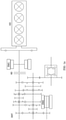
FIG. 1a ist ein schematisches Diagramm, das eine topologische Verbindungsstruktur eines Doppelmotor-Hybridantriebssystems nach dem Stand der Technik veranschaulicht, wobei das Hybridantriebssystem eine P1-Architektur und eine P3-Architektur aufweist; undFIG. 1b ist ein schematisches Diagramm, das eine topologische Verbindungsstruktur eines anderen Doppelmotor-Hybridantriebssystems nach dem Stand der Technik veranschaulicht, wobei das Hybridantriebssystem eine P2-Architektur und eine P3-Architektur aufweist. -
FIG. 2 ist ein schematisches Teilstrukturdiagramm, das die Implementierung eines Hybridantriebssystems mit einer P2-Architektur unter Verwendung eines modularen Getriebemechanismus gemäß der vorliegenden Erfindung veranschaulicht, wobei die Struktur des modularen Getriebemechanismus gemäß der vorliegenden Erfindung hauptsächlich in Form einer Schnittansicht veranschaulicht ist, und Schnittlinien jeder Komponente weggelassen sind. -
FIG. 3 ist ein schematisches Teilstrukturdiagramm, das die Implementierung eines Hybridantriebssystems mit einer P1-Architektur unter Verwendung eines modularen Getriebemechanismus gemäß der vorliegenden Erfindung veranschaulicht, wobei die Struktur des modularen Getriebemechanismus gemäß der vorliegenden Erfindung hauptsächlich in Form einer Schnittansicht veranschaulicht ist, und Schnittlinien jeder Komponente weggelassen sind. - Beispielhafte Ausführungsformen der vorliegenden Erfindung werden nachstehend unter Bezugnahme auf die Zeichnungen beschrieben. Es sollte beachtet werden, dass sich in der vorliegenden Erfindung "axiale(n) Richtung", "radiale(n) Richtung" und "Umfangsrichtung" auf eine axiale Richtung, eine radiale Richtung und eine Umfangsrichtung einer Motorausgangswelle beziehen. "Eine axiale Seite" bezieht sich auf die rechte Seite in. 1 und
FIG. 3 , "die andere axiale Seite" bezieht sich auf die linke Seite inFIG. 2 undFIG. 3 , "radiale Außenseite" bezieht sich auf die Oberseite inFIG. 2 undFIG. 3 (das heißt die von einer Mittelachse O abgewandte Seite) und "radiale Innenseite" bezieht sich auf die untere Seite inFIG. 2 undFIG. 3 (das heißt die Seite nahe der Mittelachse O). - Ein Hybridantriebssystem mit einer P2-Architektur, das unter Verwendung eines modularen Getriebemechanismus für ein Hybridantriebssystem gemäß der vorliegenden Erfindung implementiert ist, wird nachstehend zuerst beschrieben.
- Das Hybridantriebssystem mit der P2-Architektur gemäß der vorliegenden Erfindung umfasst einen modularen Getriebemechanismus für ein Hybridantriebssystem gemäß der vorliegenden Erfindung, einen Motor (nicht dargestellt), ein Getriebe (nicht dargestellt) und dergleichen.
- Wie in
FIG. 2 dargestellt, umfasst der modulare Getriebemechanismus für ein Hybridantriebssystem ein Gehäuse 1, einen Kühlmantel 2, einen Motor 3, eine Rotorträgeranordnung 4, eine Kupplung 5, einen konzentrischen Nehmerzylinder 6, eine Motorausgangswelle 7, einen Stoßdämpfer 8 und eine Ausgangsanordnung 9, die zusammengebaut sind, und alle vorstehend erwähnten Komponenten sind auf koaxiale Weise zusammengebaut. - Insbesondere ist das Gehäuse 1 des modularen Getriebemechanismus an einem Motorkörper oder einem Getriebegehäuse beispielsweise durch eine Schraube befestigt, sodass das Gehäuse 1 relativ zum Motor und dem Getriebe des Hybridantriebssystems befestigt ist.
- Das Gehäuse 1 umfasst einen radialen Gehäuseabschnitt 11, einen ersten axialen Gehäuseabschnitt 12 und einen zweiten axialen Gehäuseabschnitt 13, die einstückig gebildet sind. Der radiale Gehäuseabschnitt 11 erstreckt sich ungefähr in einer radialen Richtung R, und der erste axiale Gehäuseabschnitt 12 und der zweite axiale Gehäuseabschnitt 13 erstrecken sich von einem radialen Außenseitenende des radialen Gehäuseabschnitts 11 in Richtung der anderen axialen Seite und einer axialen Seite in einer axialen Richtung A, sodass ein Raum, der vollständig vom ersten axialen Gehäuseabschnitt 12 und dem zweiten axialen Gehäuseabschnitt 13 umgeben ist, durch den radialen Gehäuseabschnitt 11 in zwei Teile unterteilt wird. Ferner befindet sich der Kühlmantel 2 auf einer radialen Innenseite des zweiten axialen Gehäuseabschnitts 13 und ist an dem zweiten axialen Gehäuseabschnitt 13 befestigt, und ein Strömungskanal für eine Kühlflüssigkeit (beispielsweise Wasser) ist zwischen dem Kühlmantel 2 und dem zweiten axialen Gehäuseabschnitt 13 gebildet, um den Kühlmantel 2 in die Lage zu versetzen, einen Stator 31 des Motors 3 zu kühlen. Darüber hinaus kann der Kühlmantel 2 auch den Stator 31 tragen.
- Ferner umfasst der Motor 3 den Stator 31 und einen Rotor 32, der sich auf einer radialen Innenseite des Stators 31 befindet und in der Lage ist, sich relativ zum Stator 31 zu drehen. Der Stator 31 befindet sich auf einer radialen Innenseite des Kühlmantels 2 und ist an dem Kühlmantel 2 befestigt, und der Rotor 32 kann sich relativ zum Stator 31 in einem vom Stator 31 erzeugten Magnetfeld drehen, wodurch eine Antriebskraft/ein -drehmoment ausgegeben wird.
- Ferner ist die Rotorträgeranordnung 4 fest mit dem Rotor 32 verbunden und befindet sich auf einer radialen Innenseite des Rotors 32, und die Rotorträgeranordnung 4 ist konfiguriert, um die Antriebskraft/das -drehmoment vom Rotor 32 zu übertragen, während sie den Rotor 32 von der radialen Innenseite trägt. Insbesondere umfasst die Rotorträgeranordnung 4 eine Rotorhalterung 41 und einen Rotorflansch 42, die aneinander befestigt sind.
- Die Rotorhalterung 41 befindet sich auf der radialen Innenseite des Rotors 32. Die Rotorhalterung 41 ist direkt und fest mit dem Rotor 32 beispielsweise durch Presspassung verbunden, und die Rotorhalterung 41 ist konfiguriert, um den Rotor 32 zu tragen.
- Der Rotorflansch 42 befindet sich auf einer radialen Innenseite der Rotorhalterung 41 und ist fest mit der Rotorhalterung 41 verbunden, sodass der Rotorflansch 42 die Rotorhalterung 41 und den Rotor 32 tragen kann. Der Rotorflansch 42 umfasst einen radialen Rotorflanschabschnitt 421, der sich in der radialen Richtung erstreckt, und einen axialen Rotorflanschabschnitt 422, der sich von einem radialen Innenseitenende des radialen Rotorflanschabschnitts 421 in Richtung einer axialen Seite erstreckt. Ein radiales Außenseitenende des radialen Rotorflanschabschnitts 421 ist fest mit der Rotorhalterung 41 verbunden. Der axiale Rotorflanschabschnitt 422 überlappt die Rotorhalterung 41 in der axialen Richtung A, sodass die Rotorhalterung 41, der axiale Rotorflanschabschnitt 421 und der axiale Rotorflanschabschnitt 422 einen Einbauraum für die Kupplung 5 umgeben und bilden.
- Zusätzlich ist der axiale Abschnitt 422 des Rotorflansches ferner mit einem axialen Anschlag 423 versehen, der konfiguriert ist, um die Kupplung 5 axial zu positionieren. Ferner befindet sich die Kupplung 5 zwischen der Rotorhalterung 41 und dem Rotorflansch 42 und ist speziell in dem vorstehend erwähnten Einbauraum installiert, der von der Rotorhalterung 41, dem radialen Rotorflanschabschnitt 421 und dem axialen Rotorflanschabschnitt 422 umgeben und gebildet wird. Daher befindet sich die Kupplung 5 an einer axialen Seite des radialen Rotorflanschabschnitts 421 und an einer radialen Außenseite des axialen Rotorflanschabschnitts 422.
- Die Kupplung 5 umfasst drei Druckplatten (eine erste Druckplatte 51a, die sich auf der anderen axialen Seite befindet, eine dritte Druckplatte 51c, die sich auf einer axialen Seite befindet, und eine zweite Druckplatte 51b, die sich zwischen der ersten Druckplatte 51a und der dritten Druckplatte 51c befindet) parallel zu-, und voneinander beabstandet, eine Vielzahl von Reibscheiben 52 und eine Eingangs-/Ausgangshalterung 53. Die Vielzahl von Reibscheiben 52 befindet sich zwischen den drei Druckplatten 51a, 51b und 51c. Vorzugsweise sind einige Reibscheiben 52 der Vielzahl von Reibscheiben 52 an den Druckplatten 51a, 51b und 51c befestigt, und die anderen Reibscheiben 52 sind an der Eingangs-/Ausgangshalterung 53 befestigt. Die drei Druckplatten 51a, 51b und 51c ermöglichen es der Vielzahl von Reibscheiben 52, in Antriebskopplung/-entkopplung miteinander zu stehen. Ferner sind die an der Eingangs-/Ausgangshalterung 53 befestigten Reibscheiben 52 vorzugsweise doppelseitige Reibscheiben. Die drei Druckplatten 51a, 51b und 51c stehen ferner in Umfangsrichtung immer in Antriebskopplung mit der Rotorträgeranordnung 4, insbesondere stehen die drei Druckplatten 51a, 51b und 51c durch Verzahnungen immer in Antriebskopplung mit dem axialen Rotorflanschabschnitt 422. Der auf dem axialen Rotorflanschabschnitt 422 angeordnete axiale Anschlag 423 befindet sich in einer Position auf einer axialen Seite der dritten Druckplatte 51c, die einer axialen Seite unter den drei Druckplatten 51a, 51b und 51c am nächsten ist, um die Kupplung 5 von einer axialen Seite axial zu begrenzen. Da die drei Druckplatten 51a, 51b und 51c in Antriebskopplung mit dem Rotorflansch 42 stehen, anstatt direkt mit der Rotorhalterung 41 verbunden zu sein, wird verhindert, dass von der Kupplung 5 erzeugte Wärme direkt auf den Rotor 32 übertragen wird, und somit ist der Einfluss der von der Kupplung 5 erzeugten Wärme auf den Rotor 32 sehr gering.
- Außerdem ist unter den drei Druckplatten 51a, 51b und 51c die Masse der zweiten Druckplatte 51b viel größer als die der ersten Druckplatte 51a und die der dritten Druckplatte 51c, sodass die Wärmekapazität der ganzen Kupplung 5 verbessert wird. Ferner umfasst der konzentrische Nehmerzylinder 6 einen Zylinderkörper 61, der an einem radialen Innenseitenende des radialen Gehäuseabschnitts 11 befestigt ist, ein modulares Kupplungsbetätigungsglied 62, ein Ausrücklager 63 und einen Kolben 64. Ein Teil des Zylinderkörpers 61 des konzentrischen Nehmerzylinders 6 erstreckt sich vom radialen Innenseitenende des radialen Gehäuseabschnitts 11 zur radialen Innenseite ungefähr in der radialen Richtung R, und der andere Teil des Zylinderkörpers 61 erstreckt sich vom radialen Innenseitenende des vorstehend erwähnten Teils in Richtung einer axialen Seite in der axialen Richtung A, sodass der andere Teil des Zylinderkörpers 61 auf einer radialen Innenseite des axialen Rotorflanschabschnitts 422 angeordnet ist, und den axialen Rotorflanschabschnitt 422 in der Achsrichtung A überlappt.
- Das modulare Kupplungsbetätigungsglied 62 ist in dem Gehäuse 1 angeordnet, und durch die Steuerung von Hochdrucköl ermöglicht das modulare Kupplungsbetätigungsglied 62 dem Ausrücklager 63, einen axialen Druck auf den Kolben 64 auszuüben oder aufzuheben, um das Ineingriffgehen/Außereingriffgehen der Kupplung 5 zu steuern. Der modulare Kupplungsbetätigungsglied 62 weist die gleiche Struktur wie ähnliche Mechanismen im Stand der Technik auf, und wird somit in der vorliegenden Beschreibung nicht im Detail beschrieben.
- Ein Innenring des Ausrücklagers 63 liegt in der axialen Richtung A am modularen Kupplungsbetätigungsglied 62 an, und ein Außenring des Ausrücklagers 63 liegt in axialer Richtung A an dem Kolben 64 an, sodass das Ausrücklager 63 den axialen Druck vom modularen Kupplungsbetätigungsglied 62 erfolgreich zum Kolben 64 übertragen kann.
- Ein Teil des Kolbens 64 dient dazu, gegen den Außenring des Ausrücklagers 63 anzustoßen, und der andere Teil davon geht durch ein Durchgangsloch, das in dem radialen Rotorflanschabschnitt 421 gebildet ist, und drückt von der anderen axialen Seite gegen die erste Druckplatte 51a, sodass der Kolben 64 mit dem axialen Anschlag 423 zusammenwirken kann, der an dem axialen Rohrflanschabschnitt 422 angeordnet ist, um die Kupplung 5 axial zu begrenzen.
- Wenn das Ausrücklager 63 durch das modulare Kupplungsbetätigungsglied 62 angetrieben wird, um den axialen Druck auf den Kolben 64 in Richtung einer axialen Seite auszuüben, übt der Kolben 64 auf diese Weise Druck auf die erste Druckplatte 51a in Richtung einer axialen Seite aus, bis die Vielzahl von Reibscheiben 52 zwischen den drei Druckplatten 51a, 51b und 51c vollständig miteinander in Eingriff steht, sodass die Kupplung 5 in Eingriff steht; wenn das Ausrücklager 63 den vorstehend erwähnten axialen Druck aufhebt, der auf den Kolben 64 ausgeübt wird, können die Reibscheiben 52 zwischen den drei Druckplatten 51a, 51b und 51c unter der Wirkung beispielsweise einer Rückstellfeder (nicht dargestellt) außer Eingriff gebracht werden, sodass die Kupplung 5 außer Eingriff gebracht wird.
- Ferner befindet sich eine Motorausgangswelle 7 auf radialen Innenseiten sowohl des konzentrischen Nehmerzylinders 6 als auch der Rotorträgeranordnung 4. Die Motorausgangswelle 7 umfasst einen Wellenabschnitt 71, der sich linear in der axialen Richtung A erstreckt, und einen Mittelflansch 72, der an einem axialen Ende des Wellenabschnitts 71 befestigt ist, und der Mittelflansch 72 erstreckt sich in der radialen Richtung R. Ein radiales Außenseitenende von der Mittelflansch 72 ist an der Eingangs-/Ausgangshalterung 53 der Kupplung 5 befestigt.
- Ferner ist der Stoßdämpfer 8 am anderen axialen Ende des Wellenabschnitts 71 der Motorausgangswelle 7 befestigt, und der Stoßdämpfer 8 befindet sich auf der anderen axialen Seite des radialen Gehäuseabschnitts 11 und die andere axiale Seite des konzentrischen Nehmerzylinders 6 und befindet sich auf einer radialen Innenseite des ersten axialen Gehäuseabschnitts 12; und der Stoßdämpfer 8 ist konfiguriert, um Torsionsschwingungen des Motors abzuschwächen, sodass eine Antriebskraft/ein - drehmoment vom Motor so gleichmäßig wie möglich auf die Motorausgangswelle 7 übertragen werden kann.
- Ferner umfasst die Ausgangsanordnung 9 eine flexible Platte 91 und einen Nabenkern 92 der flexiblen Platte, die miteinander verbunden sind. Ein radiales Außenseitenende der flexiblen Platte 91 ist an der Rotorhalterung 41 beispielsweise durch eine Schraube befestigt, und ein radiales Innenseitenende der flexiblen Platte 91 ist an dem Nabenkern 92 der flexiblen Platte befestigt. Der Nabenkern 92 der flexiblen Platte ist konfiguriert, um mit einer Eingangswelle des Getriebes in Antriebskopplung zu stehen.
- Um sicherzustellen, dass der Rotorflansch 42 durch den Zylinderkörper 61 relativ zum Zylinderkörper 61 des konzentrischen Nehmerzylinders 6 drehbar gelagert ist, umfasst der modulare Getriebemechanismus außerdem ein Lager (zweireihiges Kugellager) B1, das sich zwischen den axialen Rotorflanschabschnitt 422 und dem Zylinderkörper 61 befindet. Um sicherzustellen, dass der Zylinderkörper 61 des konzentrischen Nehmerzylinders 6 von der Motorausgangswelle 7 relativ zur Motorausgangswelle 7 drehbar getragen wird, umfasst der modulare Getriebemechanismus zwei Lager (ein einreihiges Rillenkugellager) und ein Nadellager) B3 und B2, die sich zwischen dem Zylinderkörper 61 und der Motorausgangswelle 7 befinden. Außenringe und Innenringe der vorstehend genannten Lager sind alle durch entsprechende Strukturen axial begrenzt.
- Auf diese Weise steht in dem Hybridantriebssystem mit der in
FIG. 2 dargestellten P2-Architektur, - einerseits die Motorausgangswelle 7 des modularen Getriebemechanismus in Antriebskopplung mit einer Kurbelwelle des Motors, sodass die Antriebskraft/das - drehmoment des Motors auf die Motorausgangswelle 7 übertragen werden kann und die Motorausgangswelle 7 ist ferner fest mit der Eingangs-/Ausgangshalterung 53 der Kupplung 5 verbunden, sodass die Antriebskraft/das -drehmoment von der Motorausgangswelle 7 direkt auf die Rotorträgeranordnung 4 übertragen werden kann, wenn die Kupplung 5 in Eingriff steht; und
- andererseits ist die Rotorträgeranordnung 4 fest mit dem Rotor 32 verbunden, sodass die Antriebskraft/das -drehmoment vom Rotor 32 des Motors 3 direkt auf die Rotorträgeranordnung 4 übertragen werden kann, sodass die Antriebskraft/das - drehmoment von der Motorausgangswelle 7 und die Antriebskraft/das -drehmoment vom Rotor 32 des Motors 3 an der Rotorträgeranordnung 4 kombiniert werden können. Ferner steht die Rotorträgeranordnung 4 des modularen Getriebemechanismus mittels der Ausgangsanordnung 9 in Antriebskopplung mit der Eingangswelle des Getriebes. Daher kann die kombinierte Antriebskraft/das - drehmoment mittels der Ausgangsanordnung 9 auf die Eingangswelle des Getriebes übertragen werden.
- Genauer gesagt, in dem Hybridantriebssystem mit der in
FIG. 2 dargestellten P2-Architektur ist ein Übertragungsweg der Antriebskraft/des -drehmoments vom Motor wie folgt: die Motorausgangswelle 7 → die Eingangs-/Ausgangshalterung 53 der Kupplung 5 → die Reibscheiben 52 der Kupplung 5 → die Druckplatten 51a, 51b und 51c der Kupplung 5 → der Rotorflansch 42 → die Rotorhalterung 41 → die flexible Platte 91 → der Nabenkern 92 der flexiblen Platte → die Eingangswelle des Getriebes; und ein Übertragungsweg der Antriebskraft/des -drehmoments vom Motor 3 ist wie folgt: der Rotor 32 → die Rotorhalterung 41 → die flexible Platte 91 → der Nabenkern 92 der flexiblen Platte → die Eingangswelle des Getriebes. - Das Hybridantriebssystem mit der P2-Architektur, das unter Verwendung des modularen Getriebemechanismus für ein Hybridantriebssystem gemäß der vorliegenden Erfindung implementiert ist, ist vorstehend beschrieben, und ein Hybridantriebssystem mit einer P1-Architektur, das unter Verwendung des modularen Getriebemechanismus für ein Hybridantriebssystem gemäß der vorliegenden Erfindung implementiert ist, wird nachstehend beschrieben.
- Das Hybridantriebssystem mit der P1-Architektur umfasst einen modularen Getriebemechanismus für ein Hybridantriebssystem gemäß der vorliegenden Erfindung, einen Motor (nicht dargestelllt), ein Getriebe (nicht dargestellt) und dergleichen, wobei der modulare Getriebemechanismus für ein Hybridantriebssystem gemäß der vorliegenden Erfindung, das in
FIG. 3 dargestellt ist, im Wesentlichen die gleiche Grundstruktur wie der modulare Getriebemechanismus für ein Hybridantriebssystem gemäß der vorliegenden Erfindung aufweist, der inFIG. 2 dargestellt ist. Um das Hybridantriebssystem mit der P1-Architektur zu implementieren, wird nur eine Verbindungsbeziehung zwischen einigen Komponenten geändert. - Insbesondere wie in
FIG. 3 dargestellt, ist der Mittelflansch 72 der Motorausgangswelle 7 fest mit dem axialen Rotorflanschabschnitt 422 der Rotorträgeranordnung 4 verbunden, anstatt direkt und fest mit der Eingangs-/Ausgangshalterung 53 der Kupplung 5 verbunden zu sein; außerdem ist die Ausgangsanordnung 9 fest mit der Eingangs-/Ausgangshalterung 53 der Kupplung 5 verbunden, anstatt direkt und fest mit der Rotorträgeranordnung 4 verbunden zu sein. Auf diese Weise kann die Antriebskraft/das -drehmoment von der Motorausgangswelle 7 direkt auf die Rotorträgeranordnung 4 übertragen werden, ohne die Kupplung 5 zu passieren, die Antriebskraft/das -drehmoment vom Rotor 32 und die Antriebskraft/das -drehmoment von der Motorausgangswelle 7 werden an der Rotorträgeranordnung 4 kombiniert, und dann wird die kombinierte Antriebskraft/das - drehmoment über das Ineingriffbringen der Kupplung 5 auf die Ausgangsanordnung 9 übertragen. - Genauer gesagt, in dem Hybridantriebssystem mit der P1-Architektur, das in
FIG. 3 dargestellt ist, ist der Übertragungsweg der Antriebskraft/des -drehmoments vom Motor wie folgt: die Motorausgangswelle 7 → der Rotorflansch 42 → die Druckplatten 51a, 51b und 51c der Kupplung 5 → die Reibscheiben 52 der Kupplung 5 → die Eingangs-/Ausgangshalterung 53 der Kupplung 5 → die flexible Platte 91 → der Nabenkern 92 der flexiblen Platte → die Eingangswelle des Getriebes; und der Übertragungsweg der Antriebskraft/des -drehmoments vom Motor 3 ist wie folgt: der Rotor 32 → die Rotorhalterung 41 → der Rotorflansch 42 → die Druckplatten 51a, 51b und 51c der Kupplung 5 → die Reibscheiben 52 von der Kupplung 5 → die Eingangs-/Ausgangshalterung 53 der Kupplung 5 → die flexible Scheibe 91 → der Nabenkern 92 der flexiblen Scheibe → die Eingangswelle des Getriebes. - Es ist zu erkennen, dass aufgrund der Annahme des modularen Getriebemechanismus für ein Hybridantriebssystem gemäß der vorliegenden Erfindung das Hybridantriebssystem mit nur wenigen Änderungen in der Struktur zwischen der P1-Architektur und der P2-Architektur umgewandelt werden kann. Selbstverständlich ist die vorliegende Erfindung nicht auf die vorstehend erwähnten Ausführungsformen beschränkt, und Fachleute auf dem Gebiet der Technik können verschiedene Modifikationen an den vorstehend erwähnten Ausführungsformen der vorliegenden Erfindung vornehmen, ohne angesichts der Lehre der vorliegenden Erfindung vom Schutzumfang der vorliegenden Erfindung abzuweichen.
- (i) In der vorstehend erwähnten Beschreibung wird nur ein Betriebsmodus beschrieben, in dem der Verbrennungsmotor und der Motor jedes Hybridantriebssystems gemeinsam zum Antrieb verwendet werden. Das Laden einer Batterie durch den Motor unter Verwendung der Antriebskraft/des -drehmoments des Motors kann durch geeignetes Steuern des Ineingriffbringens/Außereingriffbringens der Kupplung implementiert werden, was hierin nicht weiter beschrieben wird.
- (ii) Da die Kupplung 5 des modularen Getriebemechanismus für ein Hybridantriebssystem gemäß der vorliegenden Erfindung auf der radialen Innenseite des Motors 3 angeordnet ist, was bewirkt, dass sich der Motor 3 und die Kupplung 5 in der axialen Richtung A überlappen, reduziert diese Anordnung eine seitliche Abmessung des gesamten Hybridantriebssystems im Vergleich zu einem Modus der Seite-an-Seite-Konfiguration der Kupplung 5 und des Motors 3 im Stand der Technik.
- (iii) Obwohl vorstehend nicht beschrieben, kann der modulare Getriebemechanismus für ein Hybridantriebssystem gemäß der vorliegenden Erfindung ferner mit einem Drehzahlsensor RE versehen sein. Der Drehzahlsensor RE kann auf dem Zylinderkörper 61 des konzentrischen Nehmerzylinders 6 und der Rotorhalterung 41 angeordnet und konfiguriert sein, um die Drehzahl des Rotors 32 zu erfassen.
- (iv) Obwohl vorstehend nicht beschrieben, kann die Kupplung 5 des modularen Getriebemechanismus für ein Hybridantriebssystem gemäß der vorliegenden Erfindung verschiedene Parameter der Kupplung basierend auf tatsächlichen Bedürfnissen (Drehmomentkapazität und Wärmekapazität der Kupplung 5) einstellen.
- (v) Obwohl vorstehend nicht beschrieben, beträgt in einem spezifischen, aber nicht einschränkenden Beispiel ein Außendurchmesser des Stators 31 277 mm, eine axiale Abmessung des Stators 31 beträgt ungefähr 80 mm und ein Innendurchmesser des Rotors 32 beträgt 182 mm.
- (vi) In der vorliegenden Erfindung können vorhandene Produkte als konzentrischer Nehmerzylinder 6 (modulares Kupplungsbetätigungsglied 62), Stoßdämpfer 8 und Ausgangsanordnung 9 verwendet werden, um die Kosten zu reduzieren.
-
- ICE
- Verbrennungsmotor
- EM1
- erster Motor
- EM2
- zweiter Motor
- K0
- Kupplung
- DHT
- Getriebe
- 1
- Gehäuse
- 11
- radialer Gehäuseabschnitt
- 12
- erster axialer Gehäuseabschnitt
- 13
- zweiter axialer Gehäuseabschnitt
- 2
- Kühlmantel
- 3
- Motor
- 31
- Stator
- 32
- Rotor
- 4
- Rotorträgeranordnung
- 41
- Rotorhalterung
- 42
- Rotorflansch
- 421
- radialer Rotorflanschabschnitt
- 422
- axialer Rotorflanschabschnitt
- 423
- axialer Anschlag
- 5
- Kupplung
- 51a
- erste Druckplatte
- 51b
- zweite Druckplatte
- 51c
- dritte Druckplatte
- 52
- Reibscheiben
- 53
- Eingangs-/Ausgangshalterung
- 6
- konzentrischer Nehmerzylinder
- 61
- Zylinderkörper
- 62
- modulares Kupplungsbetätigungsglied
- 63
- Ausrücklager
- 64
- Kolben
- 7
- Motorausgangswelle
- 71
- Wellenabschnitt
- 72
- Mittelflansch
- 8
- Stoßdämpfer
- 9
- Ausgangsanordnung
- 91
- flexible Platte
- 92
- Nabenkern einer flexiblen Platte
- RE
- Drehzahlsensor
- A
- axiale Richtung
- R
- radiale Richtung
- O
- Mittelachse
Claims (10)
- Modularer Getriebemechanismus für ein Hybridantriebssystem, umfassend:einen Motor (3), umfassend einen Stator (31) und einen Rotor (32), der sich auf einer radialen Innenseite des Stators (31) befindet und in der Lage ist, sich relativ zum Stator (31) zu drehen;eine Rotorträgeranordnung (4), die fest mit dem Rotor (32) verbunden ist und sich auf einer radialen Innenseite des Rotors (32) befindet;eine Kupplung (5), die sich auf der radialen Innenseite des Rotors (32) befindet und eine Vielzahl von Druckplatten (51a, 51b, 51c), eine Vielzahl von Reibscheiben (52) und eine Eingangs-/Ausgangshalterung (53) umfasst, wobei die Vielzahl von Druckplatten (51a, 51b, 51c) in der Lage ist, die Vielzahl von Reibscheiben (52) in Eingriff zu nehmen, um die Rotorträgeranordnung (4) in die Lage zu versetzen, in Antriebskopplung mit der Eingangs-/Ausgangshalterung (53) zu stehen;einen konzentrischen Nehmerzylinder (6), der relativ zum Stator (31) integral befestigt ist und einen Kolben (64) umfasst, wobei der Kolben (64) in der Lage ist, Druck auf die Druckplatte (51a) auszuüben, um die Vielzahl von Reibscheiben (52) in die Lage zu versetzen, miteinander in Eingriff zu stehen;eine Motorausgangswelle (7), die sich auf radialen Innenseiten sowohl des konzentrischen Nehmerzylinders (6) als auch der Rotorträgeranordnung (4) befindet; undeine Ausgangsanordnung (9),wobei die Motorausgangswelle (7) mit der Eingangs-/Ausgangshalterung (53) verbunden ist und die Ausgangsanordnung (9) mit der Rotorträgeranordnung (4) verbunden ist; oderdie Motorausgangswelle (7) mit der Rotorträgeranordnung (4) verbunden ist und die Ausgangsanordnung (9) mit der Eingangs-/Ausgangshalterung (53) verbunden ist.
- Modularer Getriebemechanismus für ein Hybridantriebssystem nach Anspruch 1, wobei die Rotorträgeranordnung (4) eine Rotorhalterung (41) und einen Rotorflansch (42) umfasst, die Rotorhalterung (41) fest mit dem Rotor (32) verbunden ist, der Rotorflansch (42) sich auf einer radialen Innenseite der Rotorhalterung (41) befindet und mit der Rotorhalterung (41) fest verbunden ist und die Kupplung (5) sich zwischen der Rotorhalterung (41) und dem Rotorflansch (42) befindet.
- Modularer Getriebemechanismus für ein Hybridantriebssystem nach Anspruch 2, wobei der Rotorflansch (42) einen radialen Rotorflanschabschnitt (421), der sich in einer radialen Richtung (R) erstreckt, und einen axialen Rotorflanschabschnitt (422) umfasst, der sich von einem radialen Innenseitenende des radialen Rotorflanschschnitts (421) in Richtung einer axialen Seite erstreckt, die Kupplung (5) sich auf einer radialen Außenseite des radialen Rotorflanschabschnitts (422) befindet und die Vielzahl von Druckplatten (51a, 51b, 51c) in einer Umfangsrichtung mit dem axialen Rotorflanschabschnitt (422) in Antriebskopplung steht.
- Modularer Getriebemechanismus für ein Hybridantriebssystem nach Anspruch 3, wobei der axiale Rotorflanschabschnitt (422) ferner mit einem axialen Anschlag (423) versehen ist und der axiale Anschlag (423) sich in einer Position auf einer axialen Seite der Druckplatte (51c) befindet, die einer axialen Seite unter der Vielzahl von Druckplatten (51a, 51b, 51c) am nächsten liegt.
- Modularer Getriebemechanismus für ein Hybridantriebssystem nach einem der Ansprüche 1 bis 4, wobei die Masse von mindestens einer Druckplatte (51b), die sich in der Mitte der Vielzahl von Druckplatten (51a, 51b, 51c) befindet, größer als die der anderen Druckplatten (51a, 51c) ist.
- Modularer Getriebemechanismus für ein Hybridantriebssystem nach einem der Ansprüche 2 bis 5, wobei ein Teil eines Zylinderkörpers (61) des konzentrischen Nehmerzylinders (6) sich auf der radialen Innenseite des axialen Rotorflanschabschnitts (422) befindet und der modulare Getriebemechanismus mindestens ein Lager (B1) umfasst, das sich zwischen dem axialen Rotorflanschabschnitt (422) und dem Zylinderkörper (61) befindet, und mindestens zwei Lager (B2, B3) sich zwischen dem Zylinderkörper (61) und der Motorausgangswelle (7) befinden.
- Modularer Getriebemechanismus für ein Hybridantriebssystem nach einem der Ansprüche 1 bis 6, wobei der modulare Getriebemechanismus ferner ein Gehäuse (1) umfasst, wobei das Gehäuse (1) relativ zu einem Motor des Hybridantriebssystems befestigt ist,das Gehäuse (1) einen sich in radialer Richtung erstreckenden radialen Gehäuseabschnitt (11) und einen ersten axialen Gehäuseabschnitt (12) und einen zweiten axialen Gehäuseabschnitt (13) umfasst, der sich von einem radialen Außenseitenende des radialen Gehäuseabschnitts (11) jeweils in Richtung der anderen axialen Seite bzw. einer axialen Seite erstreckt, undder Zylinderkörper (61) des konzentrischen Nehmerzylinders (6) auf dem radialen Gehäuseabschnitt (11) befestigt ist und der Motor (3) sich auf einer radialen Innenseite des zweiten axialen Gehäuseabschnitts (13) befindet.
- Modularer Getriebemechanismus für ein Hybridantriebssystem nach Anspruch 7, wobei der modulare Getriebemechanismus ferner einen Kühlmantel (2) umfasst, der Kühlmantel (2) sich auf der radialen Innenseite des zweiten axialen Gehäuseabschnitts (13) befindet und am zweiten axialen Gehäuseabschnitt (13) befestigt ist und der Stator (31) sich auf einer radialen Innenseite des Kühlmantels (2) befindet und am Kühlmantel (2) befestigt ist.
- Hybridantriebssystem, umfassend:einen Motor in Antriebskopplung mit einer Motorausgangswelle (7);ein Getriebe, umfassend eine Getriebeeingangswelle; undeinen modularen Getriebemechanismus für ein Hybridantriebssystem nach einem der Ansprüche 1 bis 8,wobei die Motorausgangswelle (7) fest mit der Eingangs-/Ausgangshalterung (53) verbunden ist und die Rotorträgeranordnung (4) mittels der Ausgangsanordnung (9) mit der Getriebeeingangswelle in Antriebskopplung steht.
- Hybridantriebssystem, umfassend:einen Motor in Antriebskopplung mit einer Motorausgangswelle (7);ein Getriebe, umfassend eine Getriebeeingangswelle; undeinen modularen Getriebemechanismus für ein Hybridantriebssystem nach einem der Ansprüche 1 bis 8,wobei die Motorausgangswelle (7) fest mit der Rotorträgeranordnung (4) verbunden ist und die Eingangs-/Ausgangshalterung (53) mittels der Ausgangsanordnung (9) mit der Getriebeeingangswelle in Antriebskopplung steht.
Applications Claiming Priority (1)
| Application Number | Priority Date | Filing Date | Title |
|---|---|---|---|
| PCT/CN2019/084535 WO2020215309A1 (zh) | 2019-04-26 | 2019-04-26 | 混合动力系统用模块化传动机构及混合动力系统 |
Publications (2)
| Publication Number | Publication Date |
|---|---|
| EP3960514A1 true EP3960514A1 (de) | 2022-03-02 |
| EP3960514A4 EP3960514A4 (de) | 2022-12-14 |
Family
ID=72941266
Family Applications (1)
| Application Number | Title | Priority Date | Filing Date |
|---|---|---|---|
| EP19926546.3A Withdrawn EP3960514A4 (de) | 2019-04-26 | 2019-04-26 | Modularer übertragungsmechanismus für hybridleistungssystem und hybridleistungssystem |
Country Status (4)
| Country | Link |
|---|---|
| US (1) | US20220227216A1 (de) |
| EP (1) | EP3960514A4 (de) |
| CN (1) | CN113631407A (de) |
| WO (1) | WO2020215309A1 (de) |
Cited By (2)
| Publication number | Priority date | Publication date | Assignee | Title |
|---|---|---|---|---|
| DE102024205579A1 (de) * | 2024-06-17 | 2025-12-18 | Zf Friedrichshafen Ag | Antriebsvorrichtung für ein Fahrzeug |
| DE102024119405A1 (de) * | 2024-07-09 | 2026-01-15 | Dr. Ing. H.C. F. Porsche Aktiengesellschaft | Kraftfahrzeug mit hybridem Antriebskonzept |
Family Cites Families (15)
| Publication number | Priority date | Publication date | Assignee | Title |
|---|---|---|---|---|
| JP5240128B2 (ja) * | 2009-08-31 | 2013-07-17 | トヨタ自動車株式会社 | 動力伝達装置 |
| JP2011213190A (ja) * | 2010-03-31 | 2011-10-27 | Aisin Aw Co Ltd | ハイブリッド駆動装置 |
| JP2012061912A (ja) * | 2010-09-15 | 2012-03-29 | Aisin Seiki Co Ltd | ハイブリッド車両用駆動装置およびケース |
| CN108349368B (zh) * | 2015-11-25 | 2021-10-26 | 舍弗勒技术股份两合公司 | 带分离离合器和主离合器以及布置在它们之间的操纵系统的混合动力模块 |
| DE102016212994A1 (de) * | 2016-07-15 | 2018-01-18 | Schaeffler Technologies AG & Co. KG | Kupplungseinheit, Hybridmodul und Antriebsstrang für ein Kraftfahrzeug |
| KR102274073B1 (ko) * | 2016-10-06 | 2021-07-08 | 섀플러 테크놀로지스 아게 운트 코. 카게 | 하이브리드 모듈 |
| CN107985059B (zh) * | 2016-10-26 | 2022-11-29 | 舍弗勒技术股份两合公司 | P2混动系统 |
| CN207128609U (zh) * | 2016-12-23 | 2018-03-23 | 舍弗勒技术股份两合公司 | 用于机动车的混合动力模块和驱动组件 |
| CN207128610U (zh) * | 2016-12-23 | 2018-03-23 | 舍弗勒技术股份两合公司 | 用于机动车的驱动模块和驱动组件 |
| DE102017101379A1 (de) * | 2017-01-25 | 2018-07-26 | Schaeffler Technologies AG & Co. KG | Hybridmodul mit Ableitung für Kühlfluid sowie Antriebsstrang mit Hybridmodul |
| DE102017208224A1 (de) * | 2017-05-16 | 2018-11-22 | Zf Friedrichshafen Ag | Antriebsanordnung für ein Fahrzeug |
| WO2019032352A1 (en) * | 2017-08-07 | 2019-02-14 | Schaeffler Technologies AG & Co. KG | HYBRID MODULE HAVING A CLUTCH BALANCING CHAMBER |
| DE102017130349A1 (de) * | 2017-12-18 | 2019-06-19 | Schaeffler Technologies AG & Co. KG | Elektrische Antriebseinheit und Antriebsanordnung für ein Kraftfahrzeug |
| CN108437774A (zh) * | 2018-04-02 | 2018-08-24 | 舍弗勒技术股份两合公司 | 混合动力模块和车辆 |
| CN109910585A (zh) * | 2019-03-05 | 2019-06-21 | 舍弗勒技术股份两合公司 | 混合动力模块与混合动力车辆 |
-
2019
- 2019-04-26 CN CN201980093948.7A patent/CN113631407A/zh active Pending
- 2019-04-26 EP EP19926546.3A patent/EP3960514A4/de not_active Withdrawn
- 2019-04-26 WO PCT/CN2019/084535 patent/WO2020215309A1/zh not_active Ceased
- 2019-04-26 US US17/606,727 patent/US20220227216A1/en not_active Abandoned
Cited By (2)
| Publication number | Priority date | Publication date | Assignee | Title |
|---|---|---|---|---|
| DE102024205579A1 (de) * | 2024-06-17 | 2025-12-18 | Zf Friedrichshafen Ag | Antriebsvorrichtung für ein Fahrzeug |
| DE102024119405A1 (de) * | 2024-07-09 | 2026-01-15 | Dr. Ing. H.C. F. Porsche Aktiengesellschaft | Kraftfahrzeug mit hybridem Antriebskonzept |
Also Published As
| Publication number | Publication date |
|---|---|
| CN113631407A (zh) | 2021-11-09 |
| US20220227216A1 (en) | 2022-07-21 |
| WO2020215309A1 (zh) | 2020-10-29 |
| EP3960514A4 (de) | 2022-12-14 |
Similar Documents
| Publication | Publication Date | Title |
|---|---|---|
| DE112006001432B4 (de) | Antriebsvorrichtung für ein Hybridfahrzeug | |
| DE112009003882B4 (de) | Hybridmodul für einen Antriebsstrang eines Fahrzeuges | |
| DE102004033396B4 (de) | Untersetzungsgetriebe | |
| DE102009006649B4 (de) | Doppelkupplungsanordnung | |
| EP3135522B1 (de) | Hybridmodul und verfahren zum übertragen eines drehmementes in einem triebstrang eines kraftfahrzeuges | |
| EP3448706B1 (de) | Hybridmodul und antriebsanordnung für ein kraftfahrzeug | |
| DE112012003191B4 (de) | Fahrzeugantriebsvorrichtung | |
| EP3568606B1 (de) | Hybridmodul für ein kraftfahrzeug sowie antriebsstrang mit hybridmodul | |
| DE112012004669T5 (de) | Fahrzeugantriebsvorrichtung | |
| EP3429878A1 (de) | Elektroantrieb | |
| DE102015215447A1 (de) | Antriebsmodul für einen Antriebsstrang eines Hybridfahrzeugs | |
| DE112010003293T5 (de) | Antriebsvorrichtung für ein Fahrzeug | |
| EP3337996B2 (de) | Kupplungseinrichtung für hybridantrieb | |
| DE102008033955A1 (de) | Verfahren und Vorrichtung zur Verhinderung des Spiels unter Verwendung von Schraubenfedern | |
| DE112018005388T5 (de) | Modulare elektroachskopfbaugruppe | |
| EP1174631A2 (de) | Mehrfach-Kupplungseinrichtung | |
| DE102018200567A1 (de) | Hybridantriebsmodul für ein Kraftfahrzeug | |
| WO2012149924A1 (de) | Hybridmodul für einen triebstrang eines fahrzeuges | |
| EP3960514A1 (de) | Modularer übertragungsmechanismus für hybridleistungssystem und hybridleistungssystem | |
| DE102011086712A1 (de) | Drehmomentübertragungseinrichtung | |
| WO2019242795A1 (de) | Hybridantriebseinheit in einem antriebsstrang eines kraftfahrzeugs | |
| DE102017219962A1 (de) | Drehmomentwandler, Hybridantriebsmodul und Antriebsstrang für ein Kraftfahrzeug | |
| DE102018200569B3 (de) | Hybridantriebsmodul für ein Kraftfahrzeug | |
| DE102017129266A1 (de) | Kupplung mit am Drehmomentweiterleitungsteil abgestütztem Drehmomenteinleitungsteil | |
| DE10152859A1 (de) | Fahrzeuggetriebe mit Nebenabtrieb |
Legal Events
| Date | Code | Title | Description |
|---|---|---|---|
| STAA | Information on the status of an ep patent application or granted ep patent |
Free format text: STATUS: THE INTERNATIONAL PUBLICATION HAS BEEN MADE |
|
| PUAI | Public reference made under article 153(3) epc to a published international application that has entered the european phase |
Free format text: ORIGINAL CODE: 0009012 |
|
| STAA | Information on the status of an ep patent application or granted ep patent |
Free format text: STATUS: REQUEST FOR EXAMINATION WAS MADE |
|
| 17P | Request for examination filed |
Effective date: 20211126 |
|
| AK | Designated contracting states |
Kind code of ref document: A1 Designated state(s): AL AT BE BG CH CY CZ DE DK EE ES FI FR GB GR HR HU IE IS IT LI LT LU LV MC MK MT NL NO PL PT RO RS SE SI SK SM TR |
|
| DAV | Request for validation of the european patent (deleted) | ||
| DAX | Request for extension of the european patent (deleted) | ||
| A4 | Supplementary search report drawn up and despatched |
Effective date: 20221115 |
|
| RIC1 | Information provided on ipc code assigned before grant |
Ipc: F16D 25/08 20060101ALI20221109BHEP Ipc: B60K 6/38 20071001ALI20221109BHEP Ipc: B60K 6/40 20071001AFI20221109BHEP |
|
| STAA | Information on the status of an ep patent application or granted ep patent |
Free format text: STATUS: THE APPLICATION HAS BEEN WITHDRAWN |
|
| 18W | Application withdrawn |
Effective date: 20230523 |
|
| P01 | Opt-out of the competence of the unified patent court (upc) registered |
Effective date: 20230523 |