EP3960058A1 - Staubsauger mit einem filter, wobei der filter einen faltenbalg und schaum aufweist - Google Patents
Staubsauger mit einem filter, wobei der filter einen faltenbalg und schaum aufweist Download PDFInfo
- Publication number
- EP3960058A1 EP3960058A1 EP21185695.0A EP21185695A EP3960058A1 EP 3960058 A1 EP3960058 A1 EP 3960058A1 EP 21185695 A EP21185695 A EP 21185695A EP 3960058 A1 EP3960058 A1 EP 3960058A1
- Authority
- EP
- European Patent Office
- Prior art keywords
- vacuum cleaner
- filter
- bellows
- foam
- drive unit
- Prior art date
- Legal status (The legal status is an assumption and is not a legal conclusion. Google has not performed a legal analysis and makes no representation as to the accuracy of the status listed.)
- Withdrawn
Links
- 239000006260 foam Substances 0.000 claims abstract description 55
- 239000011148 porous material Substances 0.000 claims description 19
- 239000000463 material Substances 0.000 claims description 12
- 229920001343 polytetrafluoroethylene Polymers 0.000 claims description 7
- 239000004810 polytetrafluoroethylene Substances 0.000 claims description 7
- 239000004033 plastic Substances 0.000 claims description 4
- 229920000728 polyester Polymers 0.000 claims description 4
- -1 polytetrafluoroethylene Polymers 0.000 claims description 2
- 239000002245 particle Substances 0.000 description 11
- 238000001914 filtration Methods 0.000 description 4
- 238000000034 method Methods 0.000 description 4
- 238000004140 cleaning Methods 0.000 description 3
- 230000006835 compression Effects 0.000 description 3
- 238000007906 compression Methods 0.000 description 3
- 239000000428 dust Substances 0.000 description 2
- 230000003670 easy-to-clean Effects 0.000 description 2
- 238000004519 manufacturing process Methods 0.000 description 2
- XLYOFNOQVPJJNP-UHFFFAOYSA-N water Substances O XLYOFNOQVPJJNP-UHFFFAOYSA-N 0.000 description 2
- 238000010521 absorption reaction Methods 0.000 description 1
- 238000013329 compounding Methods 0.000 description 1
- 230000001419 dependent effect Effects 0.000 description 1
- 238000011161 development Methods 0.000 description 1
- 230000018109 developmental process Effects 0.000 description 1
- 230000000694 effects Effects 0.000 description 1
- 239000010419 fine particle Substances 0.000 description 1
- 238000003825 pressing Methods 0.000 description 1
- 238000005406 washing Methods 0.000 description 1
Images
Classifications
-
- A—HUMAN NECESSITIES
- A47—FURNITURE; DOMESTIC ARTICLES OR APPLIANCES; COFFEE MILLS; SPICE MILLS; SUCTION CLEANERS IN GENERAL
- A47L—DOMESTIC WASHING OR CLEANING; SUCTION CLEANERS IN GENERAL
- A47L9/00—Details or accessories of suction cleaners, e.g. mechanical means for controlling the suction or for effecting pulsating action; Storing devices specially adapted to suction cleaners or parts thereof; Carrying-vehicles specially adapted for suction cleaners
- A47L9/10—Filters; Dust separators; Dust removal; Automatic exchange of filters
- A47L9/12—Dry filters
- A47L9/122—Dry filters flat
-
- A—HUMAN NECESSITIES
- A47—FURNITURE; DOMESTIC ARTICLES OR APPLIANCES; COFFEE MILLS; SPICE MILLS; SUCTION CLEANERS IN GENERAL
- A47L—DOMESTIC WASHING OR CLEANING; SUCTION CLEANERS IN GENERAL
- A47L9/00—Details or accessories of suction cleaners, e.g. mechanical means for controlling the suction or for effecting pulsating action; Storing devices specially adapted to suction cleaners or parts thereof; Carrying-vehicles specially adapted for suction cleaners
- A47L9/10—Filters; Dust separators; Dust removal; Automatic exchange of filters
-
- A—HUMAN NECESSITIES
- A47—FURNITURE; DOMESTIC ARTICLES OR APPLIANCES; COFFEE MILLS; SPICE MILLS; SUCTION CLEANERS IN GENERAL
- A47L—DOMESTIC WASHING OR CLEANING; SUCTION CLEANERS IN GENERAL
- A47L9/00—Details or accessories of suction cleaners, e.g. mechanical means for controlling the suction or for effecting pulsating action; Storing devices specially adapted to suction cleaners or parts thereof; Carrying-vehicles specially adapted for suction cleaners
- A47L9/10—Filters; Dust separators; Dust removal; Automatic exchange of filters
- A47L9/16—Arrangement or disposition of cyclones or other devices with centrifugal action
-
- A—HUMAN NECESSITIES
- A47—FURNITURE; DOMESTIC ARTICLES OR APPLIANCES; COFFEE MILLS; SPICE MILLS; SUCTION CLEANERS IN GENERAL
- A47L—DOMESTIC WASHING OR CLEANING; SUCTION CLEANERS IN GENERAL
- A47L9/00—Details or accessories of suction cleaners, e.g. mechanical means for controlling the suction or for effecting pulsating action; Storing devices specially adapted to suction cleaners or parts thereof; Carrying-vehicles specially adapted for suction cleaners
- A47L9/10—Filters; Dust separators; Dust removal; Automatic exchange of filters
- A47L9/16—Arrangement or disposition of cyclones or other devices with centrifugal action
- A47L9/1691—Mounting or coupling means for cyclonic chamber or dust receptacles
-
- B—PERFORMING OPERATIONS; TRANSPORTING
- B01—PHYSICAL OR CHEMICAL PROCESSES OR APPARATUS IN GENERAL
- B01D—SEPARATION
- B01D39/00—Filtering material for liquid or gaseous fluids
- B01D39/14—Other self-supporting filtering material ; Other filtering material
- B01D39/16—Other self-supporting filtering material ; Other filtering material of organic material, e.g. synthetic fibres
- B01D39/1607—Other self-supporting filtering material ; Other filtering material of organic material, e.g. synthetic fibres the material being fibrous
- B01D39/1623—Other self-supporting filtering material ; Other filtering material of organic material, e.g. synthetic fibres the material being fibrous of synthetic origin
-
- B—PERFORMING OPERATIONS; TRANSPORTING
- B01—PHYSICAL OR CHEMICAL PROCESSES OR APPARATUS IN GENERAL
- B01D—SEPARATION
- B01D39/00—Filtering material for liquid or gaseous fluids
- B01D39/14—Other self-supporting filtering material ; Other filtering material
- B01D39/16—Other self-supporting filtering material ; Other filtering material of organic material, e.g. synthetic fibres
- B01D39/1669—Cellular material
- B01D39/1676—Cellular material of synthetic origin
-
- B—PERFORMING OPERATIONS; TRANSPORTING
- B01—PHYSICAL OR CHEMICAL PROCESSES OR APPARATUS IN GENERAL
- B01D—SEPARATION
- B01D46/00—Filters or filtering processes specially modified for separating dispersed particles from gases or vapours
- B01D46/10—Particle separators, e.g. dust precipitators, using filter plates, sheets or pads having plane surfaces
- B01D46/12—Particle separators, e.g. dust precipitators, using filter plates, sheets or pads having plane surfaces in multiple arrangements
-
- B—PERFORMING OPERATIONS; TRANSPORTING
- B01—PHYSICAL OR CHEMICAL PROCESSES OR APPARATUS IN GENERAL
- B01D—SEPARATION
- B01D46/00—Filters or filtering processes specially modified for separating dispersed particles from gases or vapours
- B01D46/52—Particle separators, e.g. dust precipitators, using filters embodying folded corrugated or wound sheet material
- B01D46/521—Particle separators, e.g. dust precipitators, using filters embodying folded corrugated or wound sheet material using folded, pleated material
-
- B—PERFORMING OPERATIONS; TRANSPORTING
- B01—PHYSICAL OR CHEMICAL PROCESSES OR APPARATUS IN GENERAL
- B01D—SEPARATION
- B01D46/00—Filters or filtering processes specially modified for separating dispersed particles from gases or vapours
- B01D46/56—Filters or filtering processes specially modified for separating dispersed particles from gases or vapours with multiple filtering elements, characterised by their mutual disposition
- B01D46/62—Filters or filtering processes specially modified for separating dispersed particles from gases or vapours with multiple filtering elements, characterised by their mutual disposition connected in series
- B01D46/64—Filters or filtering processes specially modified for separating dispersed particles from gases or vapours with multiple filtering elements, characterised by their mutual disposition connected in series arranged concentrically or coaxially
-
- B—PERFORMING OPERATIONS; TRANSPORTING
- B01—PHYSICAL OR CHEMICAL PROCESSES OR APPARATUS IN GENERAL
- B01D—SEPARATION
- B01D2239/00—Aspects relating to filtering material for liquid or gaseous fluids
- B01D2239/06—Filter cloth, e.g. knitted, woven non-woven; self-supported material
- B01D2239/065—More than one layer present in the filtering material
-
- B—PERFORMING OPERATIONS; TRANSPORTING
- B01—PHYSICAL OR CHEMICAL PROCESSES OR APPARATUS IN GENERAL
- B01D—SEPARATION
- B01D2239/00—Aspects relating to filtering material for liquid or gaseous fluids
- B01D2239/12—Special parameters characterising the filtering material
- B01D2239/1208—Porosity
-
- B—PERFORMING OPERATIONS; TRANSPORTING
- B01—PHYSICAL OR CHEMICAL PROCESSES OR APPARATUS IN GENERAL
- B01D—SEPARATION
- B01D2275/00—Filter media structures for filters specially adapted for separating dispersed particles from gases or vapours
- B01D2275/40—Porous blocks
Definitions
- the invention relates to a vacuum cleaner.
- the invention relates to a vacuum cleaner with a filter.
- filters are used to protect a drive assembly of the vacuum cleaner from dirt.
- a problem here is that either the filtration effect of the filter is insufficient, cleaning of the filter is complicated and/or the filter clogs too quickly and accordingly has to be cleaned frequently or even replaced.
- the invention therefore faces the problem of providing a vacuum cleaner with a filter that has good filtration, good cleanability and a long service life.
- the invention relates to a vacuum cleaner with a filter, which has a bellows and a one-piece, partially compressed foam.
- the partially compressed foam has comparatively coarser foam and finer foam at the same time due to the partial compression.
- the filter has a very long service life due to the series-connected filter media made of coarser foam, finer foam and the bellows as a pleated medium, while at the same time there is very little pressure loss or loss of suction power. It is easy to clean, for example by washing out, and has very good filtration.
- the bellows preferably represents a fine filter. It can preferably be brushed out with a cleaning tool such as a brush and can also be washed out under running water.
- the bellows are supplemented with a partially compressed foam.
- the partially compressed foam has coarser and finer pores.
- the coarser-pored foam can therefore absorb coarser dust very well. In addition, it only represents a low air resistance, which leads to a small loss of suction power. Due to the partial compression of the foam, one side of the foam has finer pores than the other page up. The more fine-pored side of the foam also enables smaller particles to be filtered.
- an air flow generated by a drive unit of the vacuum cleaner during operation passes through three different types of filter media, which are each specifically provided for coarser, finer and very fine particles.
- the partially compressed foam is designed in one piece, it preferably has only two components as filter media in the form of the bellows and the partially compressed foam.
- the partially compressed foam comprises a ply and a further ply, the ply having a predetermined pores per inch less than a further predetermined pores per inch of the further ply, and the further ply being disposed adjacent to the bellows.
- a partially compressed foam can be produced, for example, by placing a foam with the predetermined number of pores per inch between two plates and partially compressing one plate or one side of the foam and applying pressure to the plates, for example for as long as until a desired thickness is reached. This forms the two protruding layers.
- the partially compressed foam has a layer having a predetermined pores per inch in the range of 40 to 80 ppi, more preferably 50 to 70 ppi, and another layer having another predetermined pores per inch in the range of 100 to 140 ppi, more preferably 110 to 130 ppi.
- an air flow generated by a drive assembly of the vacuum cleaner during operation first passes through the layer, then through the other layer and then through the bellows.
- the drive unit is preferably a fan.
- the filter preferably has a frame in which the bellows and/or the partially compressed foam is or are arranged.
- a material of the frame is preferably plastic, more preferably a two-component plastic.
- the frame is preferably designed as a plastic housing, more preferably in the form of a hard shell box with a seal.
- the bellows is preferably arranged therein, more preferably glued.
- the seal is preferably molded onto the frame and is soft.
- a material of the bellows is preferably PTFE (polytetrafluoroethylene).
- PTFE polytetrafluoroethylene
- the diverse and relatively simple options for compounding PTFE enable the bellows to be manufactured from PTFE in a simple and cost-effective manner.
- the PTFE bellows are stable and have a relatively long service life.
- a material of the partially compressed foam is preferably polyester.
- a polyester foam has a relatively regular cell structure and controllable porosity. Furthermore, the polyester foam has good strength, shock-absorbing properties and good acoustic absorption values and can also be washed out with water.
- the partially compressed foam has a thickness in the range of 10 to 25 mm, preferably 12 to 17 mm.
- the thickness extends from a front to a back of the partially compressed foam, particularly along the ply and the further ply of the partially compressed foam.
- the bellows preferably has a height in the range from 5 to 15, preferably 7 to 12 mm. The height of the bellows is a dimension that extends parallel to the thickness of the partially compressed foam.
- the vacuum cleaner is preferably designed as a cyclone vacuum cleaner.
- a cyclone vacuum cleaner is a bagless vacuum cleaner in which, during operation, vortices and any turbulence are generated in an incoming air stream, as a result of which the suction material, such as dust particles, is pressed in a predetermined direction and separated due to centrifugal force.
- bagless means that the suction material in the cylinder vacuum cleaner is collected directly in the separator container without a bag or similar exchangeable filter medium for receiving suction material being arranged in it, so that the user can empty the suction material from the separator container no bag or the like. Removes from the separator tank.
- the vacuum cleaner has the cyclone, the filter and, if necessary, one or more further filter media which prevent the suction material from entering the drive unit.
- the separator container has the cyclone, which preferably forms a first filter stage of the vacuum cleaner.
- the filter is located downstream of the cyclone.
- the filter preferably represents the last filter stage through which the air flow generated by the drive unit of the vacuum cleaner passes before the drive unit.
- the filter is integrated into a separator container of the vacuum cleaner in such a way that it is removed together with it when the separator container is removed from a drive unit container containing the drive unit. This means that it is still easy to clean.
- the vacuum cleaner is designed as a floor vacuum cleaner. It is equipped with a cable with a plug. Furthermore, the floor vacuum cleaner has wheels, by means of which it can be moved over a surface to be vacuumed by a user during operation.
- the vacuum cleaner has a drive unit container 7 and a separator container 6 which are detachably connected to one another.
- the drive unit container 7 has a drive unit 11 . It also has a suction inlet (not shown), to which a suction hose 8 is mounted, and an exhaust grille 15 through which an air flow generated by the drive unit 11 leaves the vacuum cleaner.
- the separator tank 6 has a cyclone 14 . Below the cyclone 14 there is a collection area 15 in which suction material (not shown) is collected. Furthermore, the separating container 6 has a filter which has a bellows 1 and a partially compressed foam 2 .
- the vacuum cleaner is designed as a floor vacuum cleaner. It has wheels 12, by means of which it can be moved over a base (not shown).
- an air flow generated by the power pack 11 has the following air path:
- the air flow flows from the suction inlet (not shown) through a duct (not shown) to an upper region of the separator tank 6, then through the separator tank 6, then through the power plant 11, then through an engine compartment (not shown), is redirected and then flows through the exhaust filter 15. Before the airflow leaves the separator vessel 6 and passes the power pack 11, it flows through the partially compressed foam 2 and then through the bellows 1.
- the filter has the bellows 1 and a one-piece, partially compressed foam 2 .
- the filter also has a frame 5 in which the bellows 1 is arranged.
- the bellows 1 is glued into the frame 5.
- the partially compressed foam 2 has a thickness d of 15 mm purely by way of example.
- the bellows 1 has, purely by way of example, a height h of 10 mm.
- Fig. 4a, b each show a sectional view of the process steps for the production of the in 1 partially compressed foam shown.
- a process step is shown in which the partially compressed foam 2 is obtained.
- the foam 2b is the in Figure 4a subjected to the process step shown until the partially compressed foam 2 has a thickness d of 15 mm. It then has a layer 3 with the pores per inch of 60 ppi and another layer 4 with a further predetermined pores per inch of 120 ppi. on.
- Figures 5a,b,c each show a foam with a different number of pores per inch and the in 1 filter shown in a sectional view when operated in a vacuum cleaner.
- An air flow generated by the drive unit passes through the respective foam or filter in the direction of the arrow.
- the drive unit is located downstream of the respective foam or filter.
- a foam 2a is shown with a pore count of 120 ppi.
- dirt particles 10 stick to its layer 3 but cannot penetrate, as a result of which the surface of the foam 2a becomes dirty and clogged.
- a foam 2b is shown with a pore count of 60 ppi.
- the dirt particles 10 partially pass through the foam 2b, partially they remain attached to its layer 3. As a result, the dirt particles either get into the drive unit or into a downstream filter.
- Figure 5c is the according Figures 4a, 4b manufactured and in the in 1 shown vacuum cleaner built-in filters shown.
- the dirt particles 10 partially pass through the layer 3, but do not pass through the further layer 4.
- the filter 2 absorbs the dirt particles 10 without becoming clogged or allowing them to pass through completely, as a result of which the in 1 flow-wise downstream bellows shown (not shown here) less dirt particles 10 penetrate.
Landscapes
- Chemical & Material Sciences (AREA)
- Chemical Kinetics & Catalysis (AREA)
- Engineering & Computer Science (AREA)
- Mechanical Engineering (AREA)
- Filters For Electric Vacuum Cleaners (AREA)
Abstract
Die Erfindung betrifft einen Staubsauger mit einem Filter, welcher einen Faltenbalg (1) und einen einstückigen, teilweise verpressten Schaum (2) aufweist.
Description
- Die Erfindung betrifft einen Staubsauger. Insbesondere betrifft die Erfindung einen Staubsauger mit einem Filter. Derartige Filter dienen dazu, ein Antriebsaggregat des Staubsaugers vor Schmutz zu schützen.
- Hierbei ist ein Problem, das entweder die Filtrationswirkung des Filters nicht ausreichend ist, ein Abreinigen des Filters kompliziert ist und/oder der Filter zu schnell verstopft und dementsprechend häufig gereinigt oder sogar getauscht werden muss.
- Der Erfindung stellt sich somit das Problem, einen Staubsauger mit einem Filter bereitzustellen, der sowohl eine gute Filtration, eine gute Abreinigbarkeit als auch eine lange Lebens- bzw. Standzeit besitzt.
- Erfindungsgemäß wird dieses Problem durch einen Staubsauger mit den Merkmalen des Patentanspruchs 1 gelöst. Vorteilhafte Ausgestaltungen und Weiterbildungen der Erfindung ergeben sich aus den nachfolgenden Unteransprüchen.
- Die mit der Erfindung erreichbaren Vorteile bestehen neben einer langen Standzeit in einer einfachen Abreinigung und gleichzeitig einer guten Filtrationsleistung bei geringem Saugkraftverlust.
- Die Erfindung betrifft einen Staubsauger mit einem Filter, welcher einen Faltenbalg und einen einstückigen, teilweise verpressten Schaum aufweist.
- Der teilweise verpresste Schaum weist in seiner Einstückigkeit durch die teilweise Verpressung gleichzeitig vergleichsweise gröberen Schaum und feineren Schaum auf. Der Filter hat aufgrund der hintereinander geschalteten Filtermedien aus gröberem Schaum, feinerem Schaum und dem Faltenbalg als plissiertes Medium eine sehr hohe Standzeit bei gleichzeitig sehr geringem Druckverlust bzw. Saugkraftverlust. Er lässt sich leicht reinigen beispielsweise durch Auswaschen und weist eine sehr gute Filtration auf.
- Der Faltenbalg stellt bevorzugt einen Feinfilter dar. Er ist bevorzugt mit einem Reinigungswerkzeug wie einem Pinsel ausbürstbar und weiterhin unter fließendem Wasser auswaschbar. Ergänzt wird der Faltenbalg mit einem teilweise verpressten Schaum. Der teilweise verpresste Schaum weist gröbere und feinere Poren auf. Der grobporigere Schaum kann somit gröberen Staub sehr gut aufnehmen. Außerdem stellt er so nur einen geringen Luftwiderstand dar, was zu einem geringen Saugkraftverlust führt. Durch die teilweise Verpressung des Schaums ist weist eine Seite des Schaums feinere Poren als die andere Seite auf. Die somit feinporigere Seite des Schaums ermöglicht auch das Filtern von kleineren Partikeln. Dadurch passiert ein von einem Antriebsaggregat des Staubsaugers bei Betrieb erzeugter Luftstrom drei unterschiedliche Arten von Filtermedien, die jeweils gezielt für gröbere, feinere und sehr feine Partikel vorgesehen sind. Dadurch, dass der teilweise verpresste Schaum einstückig ausgebildet ist, weist er bevorzugt nur zwei Komponenten als Filtermedien in Form des Faltenbalgs und des teilweise verpressten Schaums auf.
- Bevorzugt weist der teilweise verpresste Schaum eine Lage und eine weitere Lage auf, wobei die Lage eine vorbestimmte Porenanzahl pro Zoll aufweist, die kleiner als eine weitere vorbestimmte Porenanzahl pro Zoll der weiteren Lage ist, und wobei die weitere Lage benachbart zum Faltenbalg angeordnet ist. Ein derartiger teilweise verpresster Schaum ist beispielsweise dadurch herstellbar, dass ein Schaum mit der vorbestimmten Porenanzahl pro Zoll zwischen zwei Platten angeordnet wird und unter Wärmeeinwirkung auf eine Platte bzw. eine Seite des Schaums und unter Anlegen von Druck auf die Platten teilweise verpresst wird beispielsweise solange, bis eine gewünschte Dicke erreicht wird. Dadurch werden die beiden vorstehenden Lagen ausgebildet. In einer bevorzugten Ausführungsform weist der teilweise verpresste Schaum eine Lage mit einer vorbestimmten Porenanzahl pro Zoll im Bereich von 40 bis 80 ppi, bevorzugter 50 bis 70 ppi, und eine weitere Lage mit einer weiteren vorbestimmten Porenanzahl pro Zoll im Bereich von 100 bis 140 ppi, bevorzugter 110 bis 130 ppi auf.
- In einer bevorzugten Ausführungsform passiert ein von einem Antriebsaggregat des Staubsaugers bei Betrieb erzeugter Luftstrom zuerst die Lage, dann die weitere Lage und anschließend den Faltenbalg. Das hat den großen Vorteil, dass der Faltenbalg, der von einem durch ein Antriebsaggregat erzeugten Luftstrom strömungstechnisch hinter dem teilweise verpressten Schaum angeordnet ist, weniger durch Partikel belastet wird, sodass seine Standzeit erhöht wird. Das Antriebsaggregat ist bevorzugt ein Gebläse.
- Bevorzugt weist der Filter einen Rahmen auf, in dem der Faltenbalg und/oder der teilweise verpresste Schaum angeordnet ist oder sind. Ein Material des Rahmens ist bevorzugt Kunststoff bevorzugter ein Zwei-Komponenten-Kunststoff. Der Rahmen ist bevorzugt als Kunststoffgehäuse bevorzugter in Form eines Hartschalenkastens mit einer Dichtung ausgebildet. Der Faltenbalg ist bevorzugt darin angeordnet bevorzugter eingeklebt. Die Dichtung ist bevorzugt an dem Rahmen angespritzt und weich.
- Bevorzugt ist ein Material des Faltenbalgs PTFE (Polytetrafluorethylen). Die vielfältigen und relativ einfachen Möglichkeiten der Compoundierung von PTFE ermöglichen eine einfache und kostengünstige Herstellung des Faltenbalgs aus PTFE. Zudem ist der Faltenbalg aus PTFE stabil und weist eine relativ lange Lebenszeit auf.
- Ein Material des teilweisen verpressten Schaums ist bevorzugt Polyester. Ein Schaum aus Polyester weist eine relativ regelmäßige Zellstruktur und eine regulierbare Porosität auf. Weiterhin weist der Polyester-Schaumstoff, eine gute Festigkeit, stoßabsorbierende Eigenschaften und gute akustische Absorptionswerte auf und ist außerdem mit Wasser auswaschbar.
- In einer bevorzugten Ausführungsform weist der teilweise verpresste Schaum eine Dicke im Bereich von 10 bis 25 mm, bevorzugt 12 bis 17 mm auf. Die Dicke erstreckt sich von einer Vorder- zu einer Rückseite des teilweise verpressten Schaums insbesondere entlang der Lage und der weiteren Lage des teilweise verpressten Schaums. Der Faltenbalg weist bevorzugt eine Höhe im Bereich von 5 bis 15, bevorzugt 7 bis 12 mm auf. Die Höhe des Faltenbalgs ist eine Abmessung, die sich parallel zur Dicke des teilweise verpressten Schaums erstreckt.
- Der Staubsauger ist bevorzugt als Zyklon-Staubsauger ausgebildet. Unter einem Zyklon-Staubsauger ist ein beutelloser Staubsauger zu verstehen, in dem bei Betrieb in einem eintretenden Luftstrom Wirbel und etwaige Verwirbelungen erzeugt werden, wodurch das Sauggut wie z.B. Staubteilchen aufgrund von Fliehkraft in eine vorbestimmte Richtung gedrückt und abgeschieden wird. Unter dem Ausdruck "beutellos" ist zu verstehen, dass das Sauggut in dem Bodenstaubsauger direkt im Abscheiderbehälter gesammelt wird, ohne dass in diesem ein Beutel oder ein ähnliches Wechselfiltermedium zur Aufnahme von Sauggut angeordnet ist, so dass der Nutzer zur Entleerung des Saugguts aus dem Abscheiderbehälter keinen Beutel oder dgl. aus dem Abscheiderbehälter entnimmt. Der Staubsauger weist aber den Zyklon, den Filter und ggf. ein oder mehrere weitere Filtermedien auf, die verhindern, dass Sauggut in das Antriebsaggregat gelangt. Der Abscheiderbehälter weist den Zyklon auf, der bevorzugt eine erste Filterstufe des Staubsaugers bildet.
- Bevorzugt ist der Filter stromabwärts von dem Zyklon angeordnet. Bevorzugt stellt der Filter strömungstechnisch die letzte Filterstufe dar, die der von dem Antriebsaggregat des Staubsaugers erzeugte Luftstrom vor dem Antriebsaggregat passiert.
- In einer bevorzugten Ausführungsform ist der Filter in einen Abscheiderbehälter des Staubsaugers derart integriert, dass er bei Entnahme des Abscheiderbehälters von einem das Antriebsaggregat enthaltenden Antriebsaggregatbehälter mit ihm zusammen entfernt wird. Dadurch ist er weiterhin leicht reinigbar.
- In einer bevorzugten Ausführungsform ist der Staubsauger als ein Bodenstaubsauger ausgebildet. Er ist mit einem Kabel mit Stecker versehen. Ferner weist der Bodenstaubsauger Räder auf, mittels denen dieser bei Betrieb von einem Nutzer über einen zu saugenden Untergrund bewegbar ist.
- Ein Ausführungsbeispiel der Erfindung ist in den Zeichnungen rein schematisch dargestellt und wird nachfolgend näher beschrieben. Es zeigt schematisch und nicht maßstabsgerecht
- Fig. 1
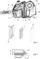
- eine Querschnittsansicht eines erfindungsgemäßen Staubsaugers;
- Fig. 2
- eine perspektivische Explosionsansicht des in
Fig. 1 gezeigten Filters; - Fig. 3
- eine Querschnittsansicht des in
Fig. 1 gezeigten Filters; - Fig. 4a, b
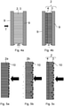
- jeweils Verfahrensschritte in Schnittansicht zur Herstellung des in
Fig. 1 gezeigten teilweise verpressten Schaums; und - Fig. 5a, b, c
- jeweils einen Schaum mit feinen Poren, groben Poren und mittels Verpressung erzeugten feinen und groben Poren, der mit feinen und groben Schmutzpartikeln beaufschlagt ist.
-
Fig. 1 zeigt eine Querschnittsansicht eines erfindungsgemäßen Staubsaugers. Der Staubsauger weist einen Antriebsaggregatbehälter 7 und einen Abscheiderbehälter 6 auf, die lösbar miteinander verbunden sind. Der Antriebsaggregatbehälter 7 weist ein Antriebsaggregat 11 auf. Ferner weist er einen Saugeingang (nicht gezeigt), an den ein Saugschlauch 8 montiert ist, und ein Abluftgitter 15 auf, durch das ein durch das Antriebsaggregat 11 erzeugter Luftstrom den Staubsauger verlässt. Der Abscheiderbehälter 6 weist einen Zyklon 14 auf. Unter dem Zyklon 14 befindet sich ein Sammelbereich 15, in dem eingesaugtes Sauggut (nicht gezeigt) gesammelt wird. Ferner weist der Abscheidebehälter 6 einen Filter auf, der einen Faltenbalg 1 und einen teilweise verpressten Schaum 2 aufweist. Der Staubsauger ist als Bodenstaubsauger ausgebildet. Er weist Räder 12 auf, mittels denen er über einen Untergrund (nicht gezeigt) bewegbar ist. - Bei Betrieb weist ein von dem Antriebsaggregat 11 erzeugter Luftstrom folgenden Luftweg auf: Der Luftstrom strömt ausgehend von dem Saugeingang (nicht gezeigt) durch einen Kanal (nicht gezeigt) zu einem oberen Bereich des Abscheiderbehälters 6, dann durch den Abscheiderbehälter 6, anschließend durch das Antriebsaggregat 11, dann durch einen Motorraum (nicht gezeigt), wird rückumgelenkt und strömt dann durch den Abluftfilter 15. Bevor der Luftstrom den Abscheiderbehälter 6 verlässt und das Antriebsaggregat 11 passiert, strömt er durch den teilweise verpressten Schaum 2 und dann durch den Faltenbalg 1.
-
Fig. 2 zeigt eine perspektivische Explosionsansicht des inFig. 1 gezeigten Filters. Der Filter weist den Faltenbalg 1 und einen einstückigen, teilweise verpressten Schaum 2 auf. Der Filter weist weiterhin einen Rahmen 5 auf, in dem der Faltenbalg 1 angeordnet ist. -
Fig. 3 zeigt eine Querschnittsansicht des inFig. 1 gezeigten Filters. Der Faltenbalg 1 ist in dem Rahmen 5 eingeklebt. Der teilweise verpresste Schaum 2 weist rein beispielhaft eine Dicke d von 15 mm auf. Der Faltenbalg 1 weist rein beispielhaft eine Höhe h von 10 mm auf. -
Fig. 4a, b zeigen jeweils Verfahrensschritte in Schnittansicht zur Herstellung des inFig. 1 gezeigten teilweise verpressten Schaums. InFig. 4a ist ein unverpresster Schaum 2b mit einer vorbestimmten Anfangsdicke beispielsweise von 25 mm und einer vorbestimmten Porenanzahl pro Zoll beispielsweise von 60 ppi zwischen zwei Platten 9 angeordnet, wobei an die Platten 9 ein Druck angelegt wird und von einer Seite Wärme T zugeführt wird. InFig. 4b ist ein Verfahrensschritt gezeigt, in dem der teilweise verpresste Schaum 2 erhalten wird. Der Schaum 2b wird dem inFig. 4a gezeigten Verfahrensschritt so lange unterzogen, bis der teilweise verpresste Schaum 2 eine Dicke d von 15 mm aufweist. Er weist dann eine Lage 3 mit der Porenanzahl pro Zoll von 60 ppi und eine weitere Lage 4 mit einer weiteren vorbestimmten Porenanzahl pro Zoll von 120 ppi. auf. -
Fig. 5a, b, c zeigen jeweils einen Schaum mit verschiedener Porenanzahl pro Zoll und den inFig. 1 gezeigten Filter in Schnittansicht bei Betrieb in einem Staubsauger. Ein durch das Antriebsaggregat erzeugter Luftstrom tritt jeweils in Pfeilrichtung durch den jeweiligen Schaum bzw. Filter. Das Antriebsaggregat liegt stromabwärts von dem jeweiligen Schaum bzw. Filter. - In
Fig. 5a ist ein Schaum 2a mit einer Porenanzahl pro Zoll von 120 ppi gezeigt. Bei Betrieb bleiben Schmutzpartikel 10 an seiner Lage 3 haften, können aber nicht eindringen, wodurch der Schaum 2a oberflächlich verdreckt und verstopft wird. - In
Fig. 5b ist ein Schaum 2b mit einer Porenanzahl pro Zoll von 60 ppi gezeigt. Bei Betrieb passieren die Schmutzpartikel 10 den Schaum 2b teilweise, teilweise bleiben sie an seiner Lage 3 hängen. Dadurch gelangen die Schmutzpartikel entweder in das Antriebsaggregat oder in einen nachfolgenden Filter. - In
Fig. 5c ist der gemäßFig 4a, 4b hergestellte und in den inFig. 1 gezeigten Staubsauger eingebaute Filter gezeigt. Bei Betrieb passieren die Schmutzpartikel 10 die Lage 3 teilweise, passieren aber nicht die weitere Lage 4. Der Filter 2 nimmt die Schmutzpartikel 10 auf, ohne zu verstopfen bzw. sie ganz durchpassieren zu lassen, wodurch in den inFig. 1 gezeigten strömungstechnisch nachgeschalteten Faltenbalg (hier nicht gezeigt) weniger Schmutzpartikel 10 eindringen. -
- d
- Dicke
- d0
- Anfangsdicke
- h
- Höhe
- T
- Temperatur
- 1
- Faltenbalg
- 2
- teilweise verpresster Schaum
- 2a
- unverpresster Schaum feinporig
- 2b
- unverpresster Schaum grobporig
- 3
- Lage
- 4
- weitere Lage
- 5
- Rahmen
- 6
- Abscheiderbehälter
- 7
- Antriebsaggregatbehälter
- 8
- Saugschlauch
- 9
- Platte
- 10
- Schmutzpartikel
- 11
- Antriebsaggregat
- 12
- Rad
- 14
- Zyklon
- 15
- Sammelbereich
Claims (10)
- Staubsauger mit einem Filter, welcher einen Faltenbalg (1) und einen einstückigen, teilweise verpressten Schaum (2) aufweist.
- Staubsauger nach Anspruch 1, dadurch gekennzeichnet, dass der teilweise verpresste Schaum (2) eine Lage (3) und eine weitere Lage (4) aufweist, wobei die Lage (3) eine vorbestimmte Porenanzahl pro Zoll aufweist, die kleiner ist als eine weitere vorbestimmte Porenanzahl pro Zoll der weiteren Lage (4) und die weitere Lage (4) benachbart zum Faltenbalg (1) angeordnet ist.
- Staubsauger nach Anspruch 1 oder 2, dadurch gekennzeichnet, dass ein von einem Antriebsaggregat (11) des Staubsaugers bei Betrieb erzeugter Luftstrom zuerst die Lage (3), dann die weitere Lage (4) und anschließend den Faltenbalg (1) passiert.
- Staubsauger nach einem der vorangehenden Ansprüche, dadurch gekennzeichnet, dass der Filter einen Rahmen (5) aufweist, in dem der Faltenbalg (1) und/oder der teilweise verpresste Schaum (2) angeordnet sind.
- Staubsauger nach einem der vorangehenden Ansprüche, dadurch gekennzeichnet, dass ein Material des Faltenbalgs (1) PTFE (Polytetrafluorethylen) ist, ein Material des teilweisen verpressten Schaums (2) Polyester (2) ist und/oder ein Material des Rahmens (5) Kunststoff ist.
- Staubsauger nach einem der vorangehenden Ansprüche, dadurch gekennzeichnet, dass der teilweise verpresste Schaum (2) eine Dicke (d) im Bereich von 10 bis 25 mm, bevorzugt 12 bis 17 mm aufweist und/oder dass der Faltenbalg (1) eine Höhe (h) im Bereich von 5 bis 15, bevorzugt 7 bis 12 mm aufweist.
- Staubsauger nach einem der vorangehenden Ansprüche, dadurch gekennzeichnet, dass er als Zyklon-Staubsauger ausgebildet ist.
- Staubsauger nach Anspruch 7, dadurch gekennzeichnet, dass der Filter stromabwärts vom Zyklon angeordnet ist.
- Staubsauger nach einem der vorangehenden Ansprüche, dadurch gekennzeichnet, dass der Filter strömungstechnisch die letzte Filterstufe darstellt, die ein von einem Antriebsaggregat (11) des Staubsaugers erzeugter Luftstrom vor dem Antriebsaggregat (11) passiert.
- Staubsauger nach einem der vorangehenden Ansprüche, dadurch gekennzeichnet, dass der Filter in einen Abscheiderbehälter (6) des Staubsaugers derart integriert ist, dass er bei Entnahme des Abscheiderbehälters (6) von einem das Antriebsaggregat (11) enthaltenden Antriebsaggregatbehälter (7) mit ihm zusammen entfernt wird.
Applications Claiming Priority (1)
| Application Number | Priority Date | Filing Date | Title |
|---|---|---|---|
| DE102020122630.6A DE102020122630A1 (de) | 2020-08-31 | 2020-08-31 | Staubsauger |
Publications (1)
| Publication Number | Publication Date |
|---|---|
| EP3960058A1 true EP3960058A1 (de) | 2022-03-02 |
Family
ID=76942826
Family Applications (1)
| Application Number | Title | Priority Date | Filing Date |
|---|---|---|---|
| EP21185695.0A Withdrawn EP3960058A1 (de) | 2020-08-31 | 2021-07-15 | Staubsauger mit einem filter, wobei der filter einen faltenbalg und schaum aufweist |
Country Status (3)
| Country | Link |
|---|---|
| EP (1) | EP3960058A1 (de) |
| CN (1) | CN114098512A (de) |
| DE (1) | DE102020122630A1 (de) |
Citations (6)
| Publication number | Priority date | Publication date | Assignee | Title |
|---|---|---|---|---|
| DE9317809U1 (de) * | 1993-11-22 | 1995-03-23 | Vorwerk & Co Interholding Gmbh, 42275 Wuppertal | Staubsauger mit einem Staubfilterbeutel und einem gesonderten Partikel- und Geruchsfilter |
| DE10316668A1 (de) * | 2003-02-21 | 2004-09-09 | Samsung Gwangju Electronics Co. Ltd. | Staubaufnahmebehälter für einen Staubsauger |
| DE102005054273A1 (de) * | 2005-11-11 | 2007-05-16 | Freudenberg Carl Kg | Filterelement mit Ausnehmungs- und/oder Durchgangsbereichen |
| DE102012005630A1 (de) * | 2012-03-22 | 2013-09-26 | Mann + Hummel Gmbh | Verfahren zur Herstellung eines Filterelements |
| DE102012219344A1 (de) * | 2012-10-23 | 2014-04-24 | BSH Bosch und Siemens Hausgeräte GmbH | Filtersystem für ein Raumpflegegerät |
| US20180296045A1 (en) * | 2017-04-12 | 2018-10-18 | Ecovacs Robotics Co., Ltd. | Handheld vacuum cleaner |
Family Cites Families (4)
| Publication number | Priority date | Publication date | Assignee | Title |
|---|---|---|---|---|
| KR100549989B1 (ko) * | 2004-04-13 | 2006-02-08 | 삼성광주전자 주식회사 | 필터조립체 및 이를 포함한 진공청소기 |
| US8950587B2 (en) * | 2009-04-03 | 2015-02-10 | Hollingsworth & Vose Company | Filter media suitable for hydraulic applications |
| WO2016205621A1 (en) * | 2015-06-19 | 2016-12-22 | Hollingsworth & Vose Company | Filter media and elements with fine staple fibers |
| CN111514654A (zh) * | 2019-02-01 | 2020-08-11 | 东丽纤维研究所(中国)有限公司 | 一种过滤材料及其用途 |
-
2020
- 2020-08-31 DE DE102020122630.6A patent/DE102020122630A1/de not_active Ceased
-
2021
- 2021-07-15 EP EP21185695.0A patent/EP3960058A1/de not_active Withdrawn
- 2021-08-27 CN CN202111000351.9A patent/CN114098512A/zh not_active Withdrawn
Patent Citations (6)
| Publication number | Priority date | Publication date | Assignee | Title |
|---|---|---|---|---|
| DE9317809U1 (de) * | 1993-11-22 | 1995-03-23 | Vorwerk & Co Interholding Gmbh, 42275 Wuppertal | Staubsauger mit einem Staubfilterbeutel und einem gesonderten Partikel- und Geruchsfilter |
| DE10316668A1 (de) * | 2003-02-21 | 2004-09-09 | Samsung Gwangju Electronics Co. Ltd. | Staubaufnahmebehälter für einen Staubsauger |
| DE102005054273A1 (de) * | 2005-11-11 | 2007-05-16 | Freudenberg Carl Kg | Filterelement mit Ausnehmungs- und/oder Durchgangsbereichen |
| DE102012005630A1 (de) * | 2012-03-22 | 2013-09-26 | Mann + Hummel Gmbh | Verfahren zur Herstellung eines Filterelements |
| DE102012219344A1 (de) * | 2012-10-23 | 2014-04-24 | BSH Bosch und Siemens Hausgeräte GmbH | Filtersystem für ein Raumpflegegerät |
| US20180296045A1 (en) * | 2017-04-12 | 2018-10-18 | Ecovacs Robotics Co., Ltd. | Handheld vacuum cleaner |
Also Published As
| Publication number | Publication date |
|---|---|
| CN114098512A (zh) | 2022-03-01 |
| DE102020122630A1 (de) | 2022-03-03 |
Similar Documents
| Publication | Publication Date | Title |
|---|---|---|
| DE69925157T2 (de) | Stielstaubsauger mit zyklonartiger luftströmung | |
| DE102004034015B4 (de) | Wirbelungs-Staubsammelvorrichtung für einen Staubsauger | |
| DE69834473T2 (de) | Stielstaubsauger mit Zyklonabscheider | |
| DE10356156B4 (de) | Wirbelungs-Staubsammelvorrichtung eines Staubsaugers | |
| DE69507836T2 (de) | Filteranordnung für einen staubsauger | |
| DE60027091T2 (de) | Staubsauger | |
| DE4427739A1 (de) | Ansaugluftfilter | |
| DE10247655A1 (de) | Zyklon-Staubsammelvorrichtung für Staubsauger | |
| WO2013013696A1 (de) | Kehrmaschine mit druckbehälter zur abreinigung des filters | |
| DE102005026811A1 (de) | Staubaustragssystem | |
| DE3341458C2 (de) | Staubsauger mit einem Abluftfilter | |
| DE102016006073A1 (de) | Brennstoffzellen-Filterelement und Brennstoffzellen-Filtersystem mit einem Brennstoffzellen-Filterelement | |
| DE202010010313U1 (de) | Abfallfiltervorrichtung für Staubsauger | |
| EP0885044B1 (de) | Konischer fluidfilter | |
| DE102020122630A1 (de) | Staubsauger | |
| DE69521418T2 (de) | Filter | |
| DE102019125002A1 (de) | Saugroboter und Verfahren zum Betrieb eines Saugroboters | |
| WO2022063586A1 (de) | Filtereinrichtung für einen staubsauger und filterabreinigungsverfahren | |
| EP3692884B1 (de) | Sauggutbehälter und handgeführter zyklon-staubsauger | |
| DE202019107210U1 (de) | Vorrichtung zur Reinigung von Akten | |
| DE102004044931A1 (de) | Filterbaugruppe und Staubsauger mit einer solchen | |
| DE102020122631B4 (de) | Staubsauger und Verfahren zur Herstellung eines Staubsaugers | |
| DE102017118474A1 (de) | Absaugvorrichtung zum Absaugen von Staubwedeln | |
| DE3216116A1 (de) | Auswechselbarer staubauffangbehaelter fuer staubsauger | |
| DE102019103014A1 (de) | Sauggutbehälter und handgeführter Zyklon-Staubsauger |
Legal Events
| Date | Code | Title | Description |
|---|---|---|---|
| PUAI | Public reference made under article 153(3) epc to a published international application that has entered the european phase |
Free format text: ORIGINAL CODE: 0009012 |
|
| STAA | Information on the status of an ep patent application or granted ep patent |
Free format text: STATUS: THE APPLICATION HAS BEEN PUBLISHED |
|
| AK | Designated contracting states |
Kind code of ref document: A1 Designated state(s): AL AT BE BG CH CY CZ DE DK EE ES FI FR GB GR HR HU IE IS IT LI LT LU LV MC MK MT NL NO PL PT RO RS SE SI SK SM TR |
|
| STAA | Information on the status of an ep patent application or granted ep patent |
Free format text: STATUS: THE APPLICATION IS DEEMED TO BE WITHDRAWN |
|
| 18D | Application deemed to be withdrawn |
Effective date: 20220903 |