EP3958552B1 - Terminal, procédé de photographie, support de stockage et dispositif électronique - Google Patents
Terminal, procédé de photographie, support de stockage et dispositif électronique Download PDFInfo
- Publication number
- EP3958552B1 EP3958552B1 EP20879708.4A EP20879708A EP3958552B1 EP 3958552 B1 EP3958552 B1 EP 3958552B1 EP 20879708 A EP20879708 A EP 20879708A EP 3958552 B1 EP3958552 B1 EP 3958552B1
- Authority
- EP
- European Patent Office
- Prior art keywords
- camera
- gap
- finding
- view
- image
- Prior art date
- Legal status (The legal status is an assumption and is not a legal conclusion. Google has not performed a legal analysis and makes no representation as to the accuracy of the status listed.)
- Active
Links
Images


Classifications
-
- H—ELECTRICITY
- H04—ELECTRIC COMMUNICATION TECHNIQUE
- H04N—PICTORIAL COMMUNICATION, e.g. TELEVISION
- H04N23/00—Cameras or camera modules comprising electronic image sensors; Control thereof
- H04N23/60—Control of cameras or camera modules
- H04N23/63—Control of cameras or camera modules by using electronic viewfinders
- H04N23/631—Graphical user interfaces [GUI] specially adapted for controlling image capture or setting capture parameters
- H04N23/632—Graphical user interfaces [GUI] specially adapted for controlling image capture or setting capture parameters for displaying or modifying preview images prior to image capturing, e.g. variety of image resolutions or capturing parameters
-
- H—ELECTRICITY
- H04—ELECTRIC COMMUNICATION TECHNIQUE
- H04N—PICTORIAL COMMUNICATION, e.g. TELEVISION
- H04N23/00—Cameras or camera modules comprising electronic image sensors; Control thereof
- H04N23/50—Constructional details
-
- H—ELECTRICITY
- H04—ELECTRIC COMMUNICATION TECHNIQUE
- H04N—PICTORIAL COMMUNICATION, e.g. TELEVISION
- H04N23/00—Cameras or camera modules comprising electronic image sensors; Control thereof
- H04N23/50—Constructional details
- H04N23/51—Housings
-
- H—ELECTRICITY
- H04—ELECTRIC COMMUNICATION TECHNIQUE
- H04N—PICTORIAL COMMUNICATION, e.g. TELEVISION
- H04N23/00—Cameras or camera modules comprising electronic image sensors; Control thereof
- H04N23/57—Mechanical or electrical details of cameras or camera modules specially adapted for being embedded in other devices
-
- H—ELECTRICITY
- H04—ELECTRIC COMMUNICATION TECHNIQUE
- H04N—PICTORIAL COMMUNICATION, e.g. TELEVISION
- H04N23/00—Cameras or camera modules comprising electronic image sensors; Control thereof
- H04N23/58—Means for changing the camera field of view without moving the camera body, e.g. nutating or panning of optics or image sensors
-
- H—ELECTRICITY
- H04—ELECTRIC COMMUNICATION TECHNIQUE
- H04N—PICTORIAL COMMUNICATION, e.g. TELEVISION
- H04N23/00—Cameras or camera modules comprising electronic image sensors; Control thereof
- H04N23/60—Control of cameras or camera modules
- H04N23/695—Control of camera direction for changing a field of view, e.g. pan, tilt or based on tracking of objects
-
- H—ELECTRICITY
- H04—ELECTRIC COMMUNICATION TECHNIQUE
- H04N—PICTORIAL COMMUNICATION, e.g. TELEVISION
- H04N23/00—Cameras or camera modules comprising electronic image sensors; Control thereof
- H04N23/60—Control of cameras or camera modules
- H04N23/698—Control of cameras or camera modules for achieving an enlarged field of view, e.g. panoramic image capture
-
- H—ELECTRICITY
- H04—ELECTRIC COMMUNICATION TECHNIQUE
- H04N—PICTORIAL COMMUNICATION, e.g. TELEVISION
- H04N5/00—Details of television systems
- H04N5/222—Studio circuitry; Studio devices; Studio equipment
- H04N5/262—Studio circuits, e.g. for mixing, switching-over, change of character of image, other special effects ; Cameras specially adapted for the electronic generation of special effects
- H04N5/2624—Studio circuits, e.g. for mixing, switching-over, change of character of image, other special effects ; Cameras specially adapted for the electronic generation of special effects for obtaining an image which is composed of whole input images, e.g. splitscreen
-
- H—ELECTRICITY
- H04—ELECTRIC COMMUNICATION TECHNIQUE
- H04N—PICTORIAL COMMUNICATION, e.g. TELEVISION
- H04N5/00—Details of television systems
- H04N5/222—Studio circuitry; Studio devices; Studio equipment
- H04N5/262—Studio circuits, e.g. for mixing, switching-over, change of character of image, other special effects ; Cameras specially adapted for the electronic generation of special effects
- H04N5/265—Mixing
-
- H—ELECTRICITY
- H04—ELECTRIC COMMUNICATION TECHNIQUE
- H04M—TELEPHONIC COMMUNICATION
- H04M1/00—Substation equipment, e.g. for use by subscribers
- H04M1/02—Constructional features of telephone sets
- H04M1/0202—Portable telephone sets, e.g. cordless phones, mobile phones or bar type handsets
- H04M1/026—Details of the structure or mounting of specific components
- H04M1/0264—Details of the structure or mounting of specific components for a camera module assembly
-
- H—ELECTRICITY
- H04—ELECTRIC COMMUNICATION TECHNIQUE
- H04M—TELEPHONIC COMMUNICATION
- H04M2250/00—Details of telephonic subscriber devices
- H04M2250/20—Details of telephonic subscriber devices including a rotatable camera
-
- H—ELECTRICITY
- H04—ELECTRIC COMMUNICATION TECHNIQUE
- H04M—TELEPHONIC COMMUNICATION
- H04M2250/00—Details of telephonic subscriber devices
- H04M2250/52—Details of telephonic subscriber devices including functional features of a camera
Definitions
- the present disclosure relates to the field of image processing, and in particular, to a terminal, a photographing method, a storage medium, and an electronic device.
- a proportion of a display area of a terminal device in an area of the terminal device becomes greater. That is, a screen-to-body ratio of the display area (i.e., a screen) in the terminal device gradually increases.
- a front camera in the terminal device. Since common applications in current terminals, such as video communication and selfie-taking, are implemented all by front cameras, it is not possible to exclude the front cameras.
- the camera is often arranged abreast of the screen in the terminal device in relevant technologies. That is, the camera and the screen are integrated abreast at a front end of the terminal device.
- the screen-to-body ratio of the terminal device can only be improved by increasing an area of the screen in a region where the camera is not provided, and arrangement of the screen cannot be performed in a region where the camera is provided. Therefore, in relevant technologies, the screen-to-body ratio of the terminal device cannot be further improved.
- the motion adjustment module includes: a camera; a first mount, coupled to the camera; a second mount, pivotally coupled to the first mount, such that the first mount pivots relative to the second mount; a third mount, pivotally coupled to the second mount; a first actuator in communication with a processing element, that pivots the first mount relative to the second mount about a first axis in response to a first signal received by the processing element from the acceleration sensor, wherein the processing element is in communication with the acceleration sensor; and a second actuator that pivots the second mount about a second axis in response to a second signal received by the processing element from the acceleration sensor.
- Document WO 2018/080455 A1 discloses a technique including selecting at least one boundary for a panoramic image to be captured by a camera of an electronic device.
- the technique includes, based at least in part on the at least one selected boundary, moving the camera relative to a housing of the electronic device to acquire data representing a plurality of images that are associated with different imaged areas; and processing the acquired data to construct the panoramic image.
- Document US 2018/041692 A1 discloses an automatic camera adjustment method and an electronic device, where the method is applied to an electronic device with a rotatable camera.
- Embodiments of the present disclosure provide a terminal, a photographing method based on the terminal, a storage medium, and an electronic device.
- a terminal including: a housing, a display panel, and a camera.
- the camera is provided inside the housing of the terminal, and is located behind a gap formed by the display panel and the housing, the camera is facing the gap such to perform viewfinding of a photographing area through said gap, wherein a width of the gap defining the photographing area is less than a width of the camera in a vertical direction so that areas of the display panel and the camera partially coincide with each other in a front-rear direction.
- a driving assembly is provided inside the terminal, and is coupled to the camera for driving the camera to rotate in a vertical direction perpendicular to the gap and perform viewfinding in different photographing areas.
- a photographing method which is applied to the terminal.
- the terminal includes: a housing, a display panel, a camera, and a driving assembly.
- the camera is provided inside the housing of the terminal, and is located behind a gap formed by the display panel and the housing the camera is facing the gap such to perform viewfinding of a photographing area through said gap, wherein a width of the gap defining the photographing area is less than a width of the camera in a vertical direction so that areas of the display panel and the camera partially coincide with each other in a front-rear direction.
- the driving assembly is coupled to the camera for driving the camera to rotate in a vertical direction perpendicular to the gap and perform viewfinding in different photographing areas.
- the method includes steps of:
- a computer-readable storage medium configured to store a computer program which, when executed by a processor, cause the processor to perform steps of anyone of the above method embodiments.
- an electronic device including a memory and a processor.
- the memory stores a computer program therein.
- the processor is configured to execute the computer program so as to perform steps of anyone of the above method embodiments.
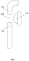
- Fig. 1 schematically shows a structure of a terminal provided according to an embodiment of the present disclosure.
- the terminal includes: a housing 102, a display panel 104, and a camera 106.
- the camera 106 is provided inside the terminal, and is located behind a gap 108 formed by the display panel 104 and the housing 102.
- the terminal in the present embodiment can solve the problem in relevant technologies that a screen-to-body ratio of a terminal device cannot be improved due to an impact from arrangement of a front camera.
- the terminal in the present embodiment includes, but is not limited to, a cellphone, a tablet computer, a PC, a wearable device and so on. Any terminal that has a front camera shooting function and includes a housing and a display panel may be used as the terminal of the present embodiment.
- the present disclosure does not make any limitation on a specific type of the terminal.
- the housing is a housing which forms encasing to the terminal.
- the housing includes an upper end surface, a lower end surface, a side end surface, a front end surface, and a back surface.
- the housing is provided at the front end surface with an opening for mounting the display panel, so as to install the display panel.
- the display panel and the housing form an entirety of the terminal.
- said housing may be a one-piece component, and may also be formed by connection of multiple components (for example, a back cover and a side periphery of a cellphone).
- the present disclosure does not make any limitation on a structure of the housing.
- the gap may be a gap that is naturally formed between the display panel and the housing in the assembling process, and may also be a gap that is further provided artificially on the basis of the gap formed in the above assembling process.
- the display panel is usually provided with a glass panel or a capacitive touch assembly outside the display panel.
- the gap may be provided below the glass panel, and a groove may be provided in an area where the glass panel corresponds to the gap.
- the camera mentioned above refers to the front camera that is located at a front end of the terminal.
- Description that the camera is provided inside the terminal and is located behind the gap formed between the display panel and the housing specifically refers to that the front camera is provided inside the terminal, i.e., between the housing and the display panel. Since the gap in the above embodiment is formed between the housing and the display panel, when the camera is located inside the terminal, the camera and the gap are distributed, respectively, at a front end surface of the terminal and inside the terminal, so as to further form a staggered distribution structure.
- the camera and the gap should be located at height positions that face each other (with reference to a position when the terminal in use is placed vertically), or the height positions at which the camera and the gap are located should be within a reasonable difference range.
- a control component, a storage component, a power supply component, a heat dissipation component and so on are further provided in the area between the housing and the display panel. The present disclosure does not make any limitation on types and arrangement manners of the components inside the terminal other than the camera.
- a width of the gap in the present embodiment is significantly less than a physical width of the camera in this direction. Therefore, it is no longer necessary to leave a space that is equal to a corresponding area of the camera on the end surface of the terminal, so that the screen-to-body ratio of the front end of the terminal can be further improved.
- the terminal further includes: a driving assembly 110, which is provided inside the terminal, and is coupled to the camera for driving the camera to rotate.
- said driving assembly is configured to control the camera to rotate, so as to enable varied positions of the camera relative to the gap for implementing photographing at different angles relative to edges of the gap.
- images acquired in a photographing process in which the camera is located at different angles relative to the edges of the gap are different. That is, in a process of controlling the camera to rotate by the driving assembly, the camera is enabled to acquire images at different angles. After performing relevant processing on these images, a complete image may be obtained for operation of a user. Therefore, the terminal in the present embodiment can also ensure a good photographing effect while improving the screen-to-body ratio of the terminal.
- said driving assembly includes at least a connection part for coupling the camera and a driving part for driving the connection part and the photographing assembly to move.
- the present disclosure does not make any limitation on specific construction of the driving assembly, and any driving assembly that can implement the above function falls into the protection scope of the present disclosure.
- Said driving part further includes a controlling part, which is configured to control the driving part to drive the connection part to rotate, so as to control rotation of the camera.
- the controlling part may adopt a controlling unit which is provided and integrated independently of the driving part, for example, a memory that stores controlling instructions, and a controller that is configured to send controlling instructions.
- the controlling part may also be combined with a controlling module of the terminal itself. That is, controlling instructions for the driving assembly and the camera are integrated into a CPU of a related terminal device.
- a direct or indirect electrical connection is formed between the controlling part and the driving part, so that the driving part, the connection part, and the camera may move correspondingly in response to controlling instructions generated by the controlling part.
- a specific connection manner between the controlling part and the driving part may be a physical connection or a wireless communication connection, and the present disclosure does not make any limitation on this matter.
- the driving assembly 110 includes:
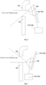
- Fig. 2 is schematic view (I) of a rotation position of the camera provided according to the present embodiment
- Fig. 3 is a schematic view (II) of a rotation position of the camera provided according to the present embodiment.
- the camera is controlled by the driving component in the driving assembly to rotate, along the rotation base plate, to a position corresponding to an upper edge of the gap and a position corresponding to a lower edge of the gap, respectively, so as to perform photographing.
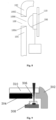
- FIG. 4 schematically shows a photographing position of the camera provided according to the present embodiment.
- the terminal includes: a housing 102, a display panel 104, a camera 106, and a driving assembly 110.
- the camera 106 is provided inside the terminal, and is located behind a gap 108 formed by the display panel 104 and the housing 102.
- the driving assembly 110 is coupled to the camera 106 for driving the camera 106 to rotate along the gap 108.
- positions where the camera performs photographing include a first edge 1082 and a second edge 1084 of the gap 108.
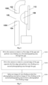
- Fig. 5 shows a flowchart of the photographing method provided according to the present embodiment. As shown in Fig. 5 , the method in the present embodiment includes steps S202 to S206.
- the camera is provided behind the gap formed by the display panel and the housing of the terminal.
- the photographing method by driving the camera to move in a direction perpendicular to the gap and perform view-finding and photographing on different photographing areas, images of view-finding on different photographing areas are acquired; and by splicing these images of view-finding on different photographing areas, a photographed view-finding image is formed, so that the photographing effect of a front camera can also be ensured while improving the screen-to-body ratio of the terminal. Therefore, the photographing method in the present embodiment can solve the problem in relevant technologies that the screen-to-body ratio of a terminal device cannot be improved due to an impact from arrangement of the front camera.
- the steps S202 and S204 may be implemented in a switched order, i.e., implementing the step S204 prior to the step S202.
- the steps S202 to S206 may be carried out by a controlling assembly, which may be integrated into a controlling module of the terminal. That is, movement of the camera and photographing in the steps S202 and S204 and the splicing processing on the images in the step S206 are realized by a CPU of a terminal device.
- the controlling assembly may also control the movement of the camera and photographing in the steps S202 and S204 by a separate first controlling component, and perform the splicing processing on the images in the step S206 by a separate second controlling component.
- the present disclosure does not make any limitation on the specific construction of the controlling assembly.
- said first edge of the gap in the step S202 indicates an edge position in the gap corresponding to the side of the housing.
- the first edge is an upper edge of the gap.
- Said first photographing area indicates a corresponding photographed image taken when the camera is located at a first edge position relative to the gap.
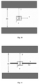
- Fig. 6 schematically shows the first photographing area provided according to the present embodiment. As shown in Fig. 6 , when the camera is located at a position corresponding to the first edge of the gap, according to the principles of optics, a photographing scope of the camera corresponds to a lower half area relative to the gap. That is, the first photographing area in the present embodiment is said lower half area.
- the camera moving to the first edge of the gap indicates that the camera moves to a position which is flush with a height of the first edge of the gap, rather than that the camera contacts with the first edge.
- Said second edge of the gap in the step S204 refers to an edge position in the gap corresponding to the side of the display panel. When the terminal is placed vertically in the common using state, the second edge is a lower edge of the gap.
- Said second photographing area indicates a corresponding photographed image taken when the camera is located at a second edge position relative to the gap.
- Fig. 7 schematically shows the second photographing area provided according to the present embodiment. As shown in Fig.
- a photographing scope of the camera corresponds to an upper half area relative to the gap. That is, the second photographing area in the present embodiment is said upper half area.
- the camera moving to the second edge of the gap indicates that the camera moves to a position which is flush with a height of the second edge of the gap, rather than that the camera contacts with the second edge.
- Photographing a portrait is taken as an example.
- a lower half body of the portrait may be photographed when the camera is located at the first edge of the gap
- an upper half body of the portrait may be photographed when the camera is located at the second edge of the gap.
- a complete portrait image may be obtained by performing splicing or combining on images of the upper half body and the lower half body.
- the method before the camera is driven to rotate to the first edge of the gap, the method further includes that:
- a time instant when the camera is initialized indicates a time instant when the terminal starts to work, which usually refers to two circumstances: the terminal enters into a power-on state from a power-off state, or the terminal switches to a working state from a sleep state.
- the controlling assembly may instruct the camera to acquire a position of the first edge and a position of the second edge.
- an image containing the first edge and the second edge of the gap therein may be acquired by the camera, and positions corresponding to the first edge and the second edge of the photographed gap are acquired by performing processing or recognition on the image.
- a direction in which the first edge or the second edge extends may be used as the direction in which the gas extends, i.e., the X axis; a direction in which the first edge faces the second edge is used as the direction perpendicular to the gap, i.e., the Y axis; and a direction in which the camera takes photograph and finds a view is used as the Z axis.
- the method further includes that:
- the centerline position between the first edge and the second edge specifically indicates a central position of the gap.
- Fig. 8 schematically shows the centerline position provided according to the present embodiment.
- a central position between the first edge 1082 and the second edge 1084 is a centerline 1086.
- Said centerline position may be used to perform focusing of the camera. After focusing of the camera is completed, initialization of the camera is completed then.
- said centerline position may also be used to restore the camera after the steps S202 to S206 of the photographing method are completed.
- the step S206 of splicing the image of view-finding on the first photographing area and the image of view-finding on the second photographing area to form a photographed view-finding image includes that:
- the feature points in the image of view-finding on the first photographing area and the image of view-finding on the second photographing area usually refer to basic pixels that form the images of view-finding, and the completed photographed view-finding image may be obtained by splicing the basic pixels.
- the process of splicing the feature points in the image of view-finding on the first photographing area and the image of view-finding on the second photographing area feature points that are coincide with each other in the image of view-finding on the first photographing area and the image of view-finding on the second photographing area are used as reference.
- a ratio of the image of view-finding on the first photographing area or the image of view-finding on the second photographing area to the photographed view-finding image is not 1:2, it is necessary to scale down an obtained image after splicing the image of view-finding on the first photographing area and the image of view-finding on the second photographing area so as to obtain the photographed view-finding image that can be displayed normally in the terminal.
- said ratio is associated with a width of the gap in the vertical direction in the present embodiment, and the present disclosure does not make any limitation on the specific setting of the ratio.
- the photographed view-finding image is stored and is used as a photographed image.
- storing of the photographed view-finding image means that the photographed view-finding image is stored in a storage module of the terminal and displayed to the user by an application such as "album".
- the photographing method of the present embodiment may also include displaying the photographed view-finding image in real time in the display panel of the terminal.
- At least a group of operations including view-finding on the first photographing area, view-finding on the second photographing area, and splicing the images of view-finding is completed within one refresh cycle of the camera.
- said one refresh cycle refers to a refresh cycle of every frame of image in the display panel. That is, in the present embodiment, operations of moving of the camera between the first edge and the second edge of the gap, photographing images of view-finding on the corresponding positions, and splicing the images of view-finding are completed within one refresh cycle.
- delay generated due to the photographing method in the present embodiment would not occur while the display panel is displaying images.
- multiple groups of operations may be completed within one refresh cycle, and an image having the best resolution in the multiple groups of operations is selected and stored.
- the method according to the above embodiments may be implemented by means of software plus a general hardware platform, and may also be implemented by means of hardware. However, in most cases, the former is a better implementation manner.
- the technical solution of the present disclosure essentially, or the part of the technical solution of the present disclosure that makes contribution to the existing technologies, may be embodied in the form of a software product.
- This computer software product is stored in a storage medium (such as a ROM/RAM, a magnetic disk, and an optical disk), and includes several instructions for causing a terminal device (which may be a cellphone, a computer, a server, or a network device) to carry out the method in various embodiments of the present disclosure.
- a cellphone as the terminal.
- the front camera is provided inside the cellphone, and view-finding by the front camera is realized though a gap between a display panel and a housing of the cellphone.
- Fig. 9 schematically shows a structure of a front camera of the cellphone provided according to the present specific embodiment. As shown in Fig. 9 , a gap 306 is formed between a housing 302 and a display screen 304 of the cellphone.
- a front camera 308 is provided inside the housing 302 of the cellphone, and faces said gap 306.
- the front camera 308 is further connected to a sliding device, such as a rotation base plate, inside the housing, and the front camera 308 specifically may slide in a width direction of the gap (i.e., a height direction when the cellphone is placed vertically) along the rotation base plate.
- the display screen 304 is covered with a glass panel 310 outside the display screen 304.
- a width of the gap 306 is notably less than a common width of the front camera 308. Therefore, a significant improvement of the screen-to-body ratio can be realized at a front end of the cellphone.
- steps when the front camera works are as follows.
- the front camera 308, when is activated, collects edges of the gap.
- Activating of the front camera indicates that the front camera 308 is initialized. This activation may be set to be performed each time after the cellphone is powered on, and may also be set to be performed each time after the cellphone ends a sleep mode.
- the front camera 308 collecting the edges of the gap may be realized by establishing a coordinate system.
- Fig. 10 schematically shows a coordinate system for operation of the front camera provided according to the present specific embodiment. As shown in Fig. 10 , the coordinate system is established through the following steps S1.2 to S 1.3.
- a coordinate system is established.
- a length direction of the gap 306 is taken as an X axis;
- a width direction of the gap 306 or a rotation direction of the front camera 308 is taken as a Y axis; and
- a direction of view-finding by the front camera 308 is taken as a Z axis.
- the X axis and the Y axis are perpendicular to each other.
- step S1.2 after the cellphone is turned on, i.e., when the front camera 308 is powered on, the front camera 308 stays still and scans upper edge information and lower edge information corresponding to the upper edge and the lower edge of the gap 306.
- the upper edge information and the lower edge information specifically refer to height positions where the upper edge and the lower edge are located.
- step S1.3 according to the upper edge information and lower edge information collected, coordinates corresponding to the upper edge information and lower edge information are marked in the coordinate system established in the step S1.1.
- step S2 according to the coordinates corresponding to the upper edge information and lower edge information of the gap 306 in the coordinate system, coordinates corresponding to a centerline of the gap 306 is calculated. Specifically, a position where the upper edge of the gap and the Y axis intersect is defined as Y1, and a position where the lower edge of the gap and the Y axis intersect is defined as Y2. A midpoint of a line segment Y1-Y2 is defined as a point (0, 0) in an X-Y coordinate plane. An X coordinate axis is established, which is the centerline 312 of the gap.
- Fig. 11 schematically shows a focusing position in the coordinate system for operation of the front camera provided according to the present specific embodiment. As shown in Fig. 11 , the X coordinate axis is established by using a position (0,0) illustrated in Fig. 11 as a focusing position.
- the front camera 308 is moved and adjusted along a direction of the Y axis to rotate to the point (0, 0), and the camera focuses on a center of the gap at this time.
- the front camera 308 is configured to automatically execute the above process, i.e., enabling the front camera 308 to focus on the coordinate (0, 0). Besides, after the front camera 308 completes working each time, the coordinate (0, 0) is also used as a restoration position for the front camera 308.
- the front camera 308 is controlled to rotate in real time to a coordinate corresponding to the upper edge information.
- the front camera 308 is at a position corresponding to the upper edge of the gap, more scenery of the lower half can be collected. Accordingly, after the front camera 308 completes focusing, the front camera 308 needs to rotate to a position of the coordinate corresponding to the upper edge information of the gap to find a view of the lower half.
- Fig. 12 schematically shows operation of the front camera when the front camera is located at a position corresponding to the upper edge of the gap provided according to the present specific embodiment. As shown in Fig. 12 , the front camera completes view-finding on the lower half when the front camera is located at the position corresponding to the upper edge of the gap.
- step S4 similar to the step S3, when the front camera 308 rotates to align with a position corresponding to the lower edge of the gap, more scenery of the upper half can be collected. Accordingly, after the front camera 308 completes view-finding on the upper half, the front camera 308 needs to rotate to a position of a coordinate corresponding to the lower edge information to find a view of the upper half.
- Fig. 13 schematically shows operation of the front camera when the front camera is located at a position corresponding to the lower edge of the gap provided according to the present specific embodiment. As shown in Fig. 13 , the front camera completes view-finding on the upper half when the front camera is located at the position corresponding to the lower edge of the gap.
- Fig. 14 schematically shows a flowchart of acquiring an image by the front camera in a frame period provided according to the present embodiment.
- an upward arrow in Fig. 14 indicates that the front camera rotates upward to acquire an image of the lower half
- a downward arrow indicates that the front camera rotates downward to acquire an image of the upper half.
- step S5 since the image of the lower half and the image of the upper half acquired in the above steps S3 and S4 are both partial images, it is required to splice the image of the lower half and the image of the upper half in real time so as to obtain a complete image of the scenery.
- a specific process of splicing the images includes following steps S5.1 to S5.5.
- an image processing chip in the cellphone such as a CPU or a DSP, extracts and analyzes feature points from a group of two images, i.e., the image of the upper half and the image of the lower half.
- the images are spliced with an increased image size.
- a scale is selected for an image obtained by splicing according to a current size scale that is displayed by the cellphone, and the principle of making the selection is to display scenery information of the image at the maximum display scale.
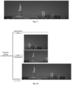
- Fig. 15 schematically shows an image of the upper half provided according to the present embodiment.
- Fig. 16 schematically shows an image of the lower half provided according to the present embodiment.
- Fig. 17 schematically shows an complete image provided according to the present embodiment. It should be noted that in order to illustrate acquiring of images in a clearer way in the present specific embodiment, Figs.
- step S5.5 the image that has been processed is displayed in the cellphone.
- the above steps S1 to S5 are required to be completed within one frame refresh cycle.
- the image displayed in the terminal device is a clear image that is subject to splicing and has obvious features.
- splicing of images in real time performed by the front camera in the photographing process includes three portions, i.e., acquiring, analyzing, and splicing the images.
- Fig. 18 schematically shows image processing provided according to the present specific embodiment.
- a photographing device is further provided.
- the photographing device is applied to the terminal in Embodiment 1 and is used to implement the above embodiments and preferred embodiments, and details that are provided foregoing will not be described any further.
- the term "module” may be a combination of software and/or hardware that can implement a predetermined function.
- the device described in the following embodiment is preferably implemented by software, it may also be contemplated that the device is possible to be implemented by hardware or a combination of software and hardware.
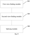
- Fig. 19 shows a block diagram of a structure of the photographing device provided according to the present embodiment. As shown in Fig. 19 , the device includes:
- the camera is provided behind the gap formed by a display panel and a housing of the terminal.
- images of view-finding on different photographing areas are acquired by said photographing device; and by splicing said images of view-finding on different photographing areas, a photographed view-finding image is formed, so that photographing effect of a front camera can also be ensured while improving a screen-to-body ratio of the terminal. Therefore, the photographing device in the present embodiment can solve the problem in relevant technologies that a screen-to-body ratio of a terminal device cannot be improved due to an impact from arrangement of a front camera.
- the step of splicing the image of view-finding on the first photographing area and the image of view-finding on the second photographing area to form the photographed view-finding image by the splicing module 306 includes that:
- the photographed view-finding image is stored as a photographed image.
- At least one group of operations including view-finding on the first photographing area, view-finding on the second photographing area, and splicing the images of view-finding is completed by said photographing device within one refresh cycle of the camera.
- the above various modules may be implemented by software or hardware, and the latter may be realized in the following manner, but is not limited to this: the above modules are all located in the same processor; or the above various modules are respectively located in different processors.
- the present disclosure further provides a storage medium configured to store a computer program which, when executed by a processor, causes the processor to perform steps of anyone of the above method embodiments.
- said storage medium may be configured to store a computer program for executing the following steps:
- said storage medium may include, but is not limited to, various mediums that can store the computer program: a USB flash disk, a read-only memory (ROM for short), a random access memory (RAM for short), a mobile hard disk drive, a magnetic disk, or an optical disk.
- the present embodiment further provides an electronic device, including a memory and a processor.
- the memory stores a computer program therein.
- the processor is configured to execute the computer program so as to perform steps of anyone of the above method embodiments.
- Said electronic device may also include a transmission device and an input-output device.
- the transmission device is coupled to said processor, and the input-output device is coupled to the processor.
- said processor may be configured to execute the following steps by using the computer program:
Landscapes
- Engineering & Computer Science (AREA)
- Signal Processing (AREA)
- Multimedia (AREA)
- Human Computer Interaction (AREA)
- Studio Devices (AREA)
Claims (15)
- Terminal, comprenant : un boîtier (102), un panneau d'affichage (104), et une caméra (106), caractérisé en ce quela caméra (106) est prévue à l'intérieur du boîtier du terminal, et est située derrière un espace (108) formé entre le panneau d'affichage (104) et le boîtier (102), la caméra faisant face à l'espace de manière à réaliser une visée d'une zone de photographie à travers ledit espace, dans lequel une largeur de l'espace (108) définissant la zone de photographie est inférieure à une largeur de la caméra (106) dans une direction verticale lorsque le terminal est placé verticalement dans un état d'usage commun de sorte que des zones du panneau d'affichage (104) et de la caméra (106) coïncident partiellement l'une avec l'autre dans une direction avant-arrière perpendiculaire à l'espace ; etun ensemble d'entraînement (101) est prévu à l'intérieur du terminal, et est couplé à la caméra (106) pour entraîner la caméra (106) à tourner dans une direction verticale perpendiculaire à l'espace et à réaliser une visée dans différentes zones de photographie.
- Terminal selon la revendication 1, caractérisé en ce que l'ensemble d'entraînement (101) comprend :une plaque de base de rotation (1102), qui est couplée à la caméra (106) ;un composant d'entraînement (1104), qui est couplé à la caméra (106) et configuré pour entraîner la caméra à tourner le long de la plaque de base de rotation (1102).
- Procédé de photographie, qui est appliqué à un terminal, caractérisé en ce que le terminal comprend : un boîtier (102), un panneau d'affichage (104), une caméra (106), et un ensemble d'entraînement (101) ; la caméra (106) est prévue à l'intérieur du boîtier du terminal, et est située derrière un espace (108) formé entre le panneau d'affichage (104) et le boîtier (102), la caméra faisant face à l'espace de manière à réaliser une visée d'une zone de photographie à travers ledit espace, dans lequel une largeur de l'espace (108) définissant la zone de photographie est inférieure à une largeur de la caméra (106) dans une direction verticale lorsque le terminal est placé verticalement dans un état d'usage commun de sorte que des zones du panneau d'affichage (104) et de la caméra (106) coïncident partiellement l'une avec l'autre dans une direction avant-arrière perpendiculaire à l'espace ; et l'ensemble d'entraînement (101) est couplé à la caméra (106) pour entraîner la caméra (106) à tourner dans une direction verticale perpendiculaire à l'espace et à réaliser une visée dans différentes zones de photographie ; et le procédé comprend les étapes consistant à :entraîner la caméra (106) à tourner vers un premier bord (1082) de l'espace (108) et à réaliser une visée sur une première zone de photographie à travers l'espace (S202) ;entraîner la caméra (106) à tourner vers un deuxième bord (1084) de l'espace (108) opposé au premier bord (1082) et à réaliser une visée sur une deuxième zone de photographie à travers l'espace (S204) ; etraccorder une image de visée sur la première zone de photographie et une image de visée sur la deuxième zone de photographie pour former une image de visée photographiée (S206).
- Procédé selon la revendication 3, caractérisé en ce que, avant l'entraînement de la caméra (106) à tourner vers le premier bord (1082) de l'espace (108), le procédé comprend en outre :la collecte d'informations de position du premier bord (1082) et du deuxième bord (1084) de l'espace (108) lorsque la caméra (106) est initialisée ; etl'établissement d'axes de coordonnées en fonction des informations de position collectées, dans lequel une direction dans laquelle l'espace s'étend est un axe X, une direction perpendiculaire à l'espace est un axe Y, une direction de visée est un axe Z.
- Procédé selon la revendication 3 ou 4, caractérisé en ce que l'ensemble d'entraînement comprend une plaque de base de rotation (1102) et un composant d'entraînement (1104), dans lequella plaque de base de rotation (1102) est couplée à la caméra (106) ;le composant d'entraînement (1104) est couplé à la caméra et configuré pour entraîner la caméra (106) à tourner le long de la plaque de base de rotation (1102).
- Procédé selon l'une quelconque des revendications 3 à 5, caractérisé en ce que l'entraînement de la caméra (106) à tourner vers le premier bord (1082) de l'espace (108) comprend :l'entraînement de la caméra à tourner vers une position qui est au même niveau qu'une hauteur du premier bord (1082) de l'espace (108) ;dans lequel l'entraînement de la caméra à tourner vers le deuxième bord (1084) de l'espace (108) opposé au premier bord (1082) comprend :
l'entraînement de la caméra à tourner vers une position qui est au même niveau qu'une hauteur du deuxième bord (1084) de l'espace (108). - Procédé selon l'une quelconque des revendications 4 à 6, caractérisé en ce que, après l'établissement d'axes de coordonnées en fonction des informations de position collectées, le procédé comprend en outre :le calcul d'une position de ligne médiane entre le premier bord (1082) et le deuxième bord (1084) en fonction des axes de coordonnées établis ; etl'entraînement de la caméra (106) à se déplacer vers la position de ligne médiane le long de l'axe Y et à réaliser la mise au point de la caméra (106).
- Procédé selon l'une quelconque des revendications 4 à 7, caractérisé en ce que la collecte d'informations de position du premier bord (1082) et du deuxième bord (1084) de l'espace (108) comprend :l'acquisition d'une image contenant le premier bord (1082) et le deuxième bord (1084) de l'espace (108) ;l'acquisition de positions correspondant au premier bord (1082) et au deuxième bord (1084) de l'espace (108) par la réalisation d'un traitement sur l'image.
- Procédé selon l'une quelconque des revendications 4 à 8, caractérisé en ce qu'un instant auquel la caméra (106) est initialisée comprend au moins un instant choisi dans un groupe se composant de :
l'instant auquel le terminal entre dans un état sous tension depuis un état hors tension, l'instant auquel le terminal passe dans un état de fonctionnement depuis un état de veille et l'instant auquel la caméra est mise sous tension. - Procédé selon l'une quelconque des revendications 3 à 9, caractérisé en ce que le raccordement de l'image de visée sur la première zone de photographie et de l'image de visée sur la deuxième zone de photographie pour former l'image de visée photographiée (S206) comprend :l'extraction de points caractéristiques dans respectivement l'image de visée sur la première zone de photographie et l'image de visée sur la deuxième zone de photographie ;le raccordement de l'image de visée sur la première zone de photographie et de l'image de visée sur la deuxième zone de photographie en fonction des points caractéristiques extraits de manière à former l'image de visée photographiée ; etla sélection d'une échelle pour l'image de visée photographiée en fonction d'une échelle d'affichage prédéfinie.
- Procédé selon l'une quelconque des revendications 3 à 10, caractérisé en ce que, après le raccordement de l'image de visée sur la première zone de photographie et de l'image de visée sur la deuxième zone de photographie pour former l'image de visée photographiée, le procédé comprend en outre :
le stockage de l'image de visée photographiée en tant qu'image photographiée. - Procédé selon l'une quelconque des revendications 3 à 11, caractérisé en ce que, après le raccordement de l'image de visée sur la première zone de photographie et de l'image de visée sur la deuxième zone de photographie pour former l'image de visée photographiée, le procédé comprend en outre :
l'entraînement de la caméra (106) à se déplacer vers la position de ligne médiane le long de l'axe Y pour restaurer la caméra (106). - Procédé selon l'une quelconque des revendications 3 à 12, caractérisé en ce qu'au moins un groupe d'opérations comprenant une opération de visée sur la première zone de photographie, une opération de visée sur la deuxième zone de photographie et une opération de raccordement des images de visée est accompli au cours d'un cycle de rafraîchissement de la caméra.
- Support de stockage lisible par ordinateur, caractérisé en ce qu'il est configuré pour stocker un programme informatique qui, lorsqu'il est exécuté par un processeur, amène le processeur à réaliser le procédé selon l'une quelconque des revendications 3 à 13.
- Dispositif électronique, comprenant une mémoire et un processeur, caractérisé en ce que la mémoire stocke un programme informatique dans celle-ci, et le processeur est configuré pour exécuter le programme informatique de manière à réaliser le procédé selon l'une quelconque des revendications 3 à 13.
Applications Claiming Priority (2)
| Application Number | Priority Date | Filing Date | Title |
|---|---|---|---|
| CN201911015379.2A CN112714236B (zh) | 2019-10-24 | 2019-10-24 | 终端及拍摄方法、存储介质、电子装置 |
| PCT/CN2020/123732 WO2021078302A1 (fr) | 2019-10-24 | 2020-10-26 | Terminal, procédé de photographie, support de stockage et dispositif électronique |
Publications (3)
| Publication Number | Publication Date |
|---|---|
| EP3958552A1 EP3958552A1 (fr) | 2022-02-23 |
| EP3958552A4 EP3958552A4 (fr) | 2023-01-18 |
| EP3958552B1 true EP3958552B1 (fr) | 2024-12-04 |
Family
ID=75540289
Family Applications (1)
| Application Number | Title | Priority Date | Filing Date |
|---|---|---|---|
| EP20879708.4A Active EP3958552B1 (fr) | 2019-10-24 | 2020-10-26 | Terminal, procédé de photographie, support de stockage et dispositif électronique |
Country Status (4)
| Country | Link |
|---|---|
| US (1) | US11825188B2 (fr) |
| EP (1) | EP3958552B1 (fr) |
| CN (1) | CN112714236B (fr) |
| WO (1) | WO2021078302A1 (fr) |
Family Cites Families (23)
| Publication number | Priority date | Publication date | Assignee | Title |
|---|---|---|---|---|
| JP4836930B2 (ja) * | 2007-12-27 | 2011-12-14 | 株式会社東芝 | 電子機器 |
| JP2011119974A (ja) * | 2009-12-03 | 2011-06-16 | Sony Corp | パノラマ画像合成装置、パノラマ画像合成方法、及びプログラム |
| US9307129B2 (en) * | 2013-05-07 | 2016-04-05 | Lg Electronics Inc. | Terminal case, mobile terminal, and mobile terminal assembly including the terminal case and the mobile terminal |
| WO2016011620A1 (fr) * | 2014-07-23 | 2016-01-28 | 华为技术有限公司 | Dispositif terminal |
| WO2016134534A1 (fr) * | 2015-02-28 | 2016-09-01 | 华为技术有限公司 | Procédé de réglage automatique d'appareil de prise de vues et de dispositif électronique |
| US9667848B2 (en) * | 2015-04-22 | 2017-05-30 | Qualcomm Incorporated | Tiltable camera module |
| CN105959565A (zh) * | 2016-06-15 | 2016-09-21 | 维沃移动通信有限公司 | 一种全景拍照方法及移动终端 |
| CN108141524A (zh) * | 2016-09-21 | 2018-06-08 | 北京小米移动软件有限公司 | 全景照片拍摄方法及装置 |
| WO2018080455A1 (fr) * | 2016-10-25 | 2018-05-03 | Hewlett-Packard Development Company, L.P. | Dispositifs électroniques ayant de multiples caméras de position |
| CN106709868A (zh) * | 2016-12-14 | 2017-05-24 | 云南电网有限责任公司电力科学研究院 | 一种图像拼接方法及装置 |
| JP6735917B2 (ja) * | 2017-05-16 | 2020-08-05 | 富士フイルム株式会社 | 撮像装置及び画像合成装置 |
| CN118042036B (zh) * | 2017-06-30 | 2026-01-06 | 华为技术有限公司 | 显示图形用户界面的方法、电子设备、程序产品和存储介质 |
| KR102378472B1 (ko) * | 2017-08-10 | 2022-03-25 | 삼성전자주식회사 | 미러를 회전 시킬수 있는 구동 장치를 포함하는 카메라를 이용하여 이미지를 획득하는 방법 및 전자 장치 |
| CN107426444B (zh) * | 2017-09-26 | 2023-11-17 | 深圳传音制造有限公司 | 移动终端 |
| WO2019165068A1 (fr) * | 2018-02-22 | 2019-08-29 | Perspective Components, Inc. | Mécanisme et procédés de réglage de caméra dynamique |
| CN110324440B (zh) * | 2018-03-29 | 2024-12-13 | 悠尼客(上海)企业管理有限公司 | 摄像头模组、全面屏移动终端及图像处理方法 |
| CN208257866U (zh) * | 2018-04-11 | 2018-12-18 | 中兴通讯股份有限公司 | 一种显示面板、摄像装置及终端 |
| CN108540608B (zh) * | 2018-04-26 | 2020-01-10 | Oppo广东移动通信有限公司 | 电子装置 |
| CN108600465A (zh) * | 2018-06-30 | 2018-09-28 | 上海爱优威软件开发有限公司 | 一种具有屏下摄像头的终端设备 |
| CN208862941U (zh) * | 2018-08-31 | 2019-05-14 | 维沃移动通信有限公司 | 一种移动终端 |
| CN109246263A (zh) * | 2018-10-31 | 2019-01-18 | 魏欣欣 | 一种全面屏电子设备及其成像方法 |
| CN111491094B (zh) * | 2019-01-28 | 2021-08-31 | 北京小米移动软件有限公司 | 摄像模组及终端 |
| CN110062084A (zh) * | 2019-05-30 | 2019-07-26 | Oppo广东移动通信有限公司 | 一种终端设备 |
-
2019
- 2019-10-24 CN CN201911015379.2A patent/CN112714236B/zh active Active
-
2020
- 2020-10-26 US US17/611,173 patent/US11825188B2/en active Active
- 2020-10-26 WO PCT/CN2020/123732 patent/WO2021078302A1/fr not_active Ceased
- 2020-10-26 EP EP20879708.4A patent/EP3958552B1/fr active Active
Also Published As
| Publication number | Publication date |
|---|---|
| WO2021078302A1 (fr) | 2021-04-29 |
| US20220217282A1 (en) | 2022-07-07 |
| CN112714236A (zh) | 2021-04-27 |
| EP3958552A1 (fr) | 2022-02-23 |
| US11825188B2 (en) | 2023-11-21 |
| CN112714236B (zh) | 2024-05-10 |
| EP3958552A4 (fr) | 2023-01-18 |
Similar Documents
| Publication | Publication Date | Title |
|---|---|---|
| KR102661185B1 (ko) | 전자 장치 및 그의 이미지 촬영 방법 | |
| RU2649773C2 (ru) | Управление камерой посредством функции распознавания лица | |
| CN109313799B (zh) | 图像处理方法及设备 | |
| KR102661614B1 (ko) | 화면 제공 방법 및 이를 지원하는 전자 장치 | |
| CN111862620B (zh) | 一种图像融合处理方法及装置 | |
| CN110290324A (zh) | 设备成像方法、装置、存储介质及电子设备 | |
| US20220345628A1 (en) | Method for image processing, electronic device, and storage medium | |
| CN110365896B (zh) | 一种控制方法及电子设备 | |
| JP7404563B2 (ja) | 画像取得方法、装置と電子機器 | |
| CN103402058A (zh) | 一种拍摄图像的处理方法及装置 | |
| KR20250130568A (ko) | 전자 장치 및 그 전자 장치에서 영상을 표시하는 방법 | |
| CN110225243A (zh) | 基于折叠屏的拍摄控制方法、装置、存储介质及移动终端 | |
| KR20240004839A (ko) | 촬영 방법, 장치 및 전자기기 | |
| EP3958552B1 (fr) | Terminal, procédé de photographie, support de stockage et dispositif électronique | |
| JP6483661B2 (ja) | 撮像制御装置、撮像制御方法およびプログラム | |
| CN111131714A (zh) | 图像采集控制方法、装置及电子设备 | |
| CN111327795B (zh) | 终端及拍摄方法、存储介质、电子装置 | |
| EP3826289B1 (fr) | Procédé de capture d'image et dispositif de capture d'image | |
| CN106921826B (zh) | 拍照模式的处理方法及装置 | |
| CN107197155B (zh) | 一种拍照后对焦的方法、系统、移动终端及存储装置 | |
| CN120405968B (zh) | 一种智能眼镜及其控制方法 | |
| CN112749600A (zh) | 人眼位置确定方法及相关产品 | |
| CN117729418A (zh) | 一种基于画面显示的人物框定方法、装置和终端设备 | |
| WO2024193050A1 (fr) | Procédé de capture d'image de dispositif électronique pliable, et dispositif électronique pliable | |
| CN118938566A (zh) | 可变通光孔模块、成像镜头模块、相机模块与电子装置 |
Legal Events
| Date | Code | Title | Description |
|---|---|---|---|
| STAA | Information on the status of an ep patent application or granted ep patent |
Free format text: STATUS: THE INTERNATIONAL PUBLICATION HAS BEEN MADE |
|
| PUAI | Public reference made under article 153(3) epc to a published international application that has entered the european phase |
Free format text: ORIGINAL CODE: 0009012 |
|
| STAA | Information on the status of an ep patent application or granted ep patent |
Free format text: STATUS: REQUEST FOR EXAMINATION WAS MADE |
|
| 17P | Request for examination filed |
Effective date: 20211117 |
|
| AK | Designated contracting states |
Kind code of ref document: A1 Designated state(s): AL AT BE BG CH CY CZ DE DK EE ES FI FR GB GR HR HU IE IS IT LI LT LU LV MC MK MT NL NO PL PT RO RS SE SI SK SM TR |
|
| A4 | Supplementary search report drawn up and despatched |
Effective date: 20221219 |
|
| RIC1 | Information provided on ipc code assigned before grant |
Ipc: H04M 1/02 20060101ALI20221213BHEP Ipc: H04N 5/262 20060101ALI20221213BHEP Ipc: H04N 5/232 20060101ALI20221213BHEP Ipc: H04N 5/225 20060101AFI20221213BHEP |
|
| DAV | Request for validation of the european patent (deleted) | ||
| DAX | Request for extension of the european patent (deleted) | ||
| REG | Reference to a national code |
Ref country code: DE Ref legal event code: R079 Free format text: PREVIOUS MAIN CLASS: H04N0005225000 Ref country code: DE Ref legal event code: R079 Ref document number: 602020042751 Country of ref document: DE Free format text: PREVIOUS MAIN CLASS: H04N0005225000 Ipc: H04N0005262000 |
|
| GRAP | Despatch of communication of intention to grant a patent |
Free format text: ORIGINAL CODE: EPIDOSNIGR1 |
|
| STAA | Information on the status of an ep patent application or granted ep patent |
Free format text: STATUS: GRANT OF PATENT IS INTENDED |
|
| RIC1 | Information provided on ipc code assigned before grant |
Ipc: H04M 1/02 20060101ALI20240521BHEP Ipc: H04N 23/698 20230101ALI20240521BHEP Ipc: H04N 23/695 20230101ALI20240521BHEP Ipc: H04N 23/58 20230101ALI20240521BHEP Ipc: H04N 23/57 20230101ALI20240521BHEP Ipc: H04N 5/262 20060101AFI20240521BHEP |
|
| INTG | Intention to grant announced |
Effective date: 20240612 |
|
| GRAS | Grant fee paid |
Free format text: ORIGINAL CODE: EPIDOSNIGR3 |
|
| GRAA | (expected) grant |
Free format text: ORIGINAL CODE: 0009210 |
|
| STAA | Information on the status of an ep patent application or granted ep patent |
Free format text: STATUS: THE PATENT HAS BEEN GRANTED |
|
| AK | Designated contracting states |
Kind code of ref document: B1 Designated state(s): AL AT BE BG CH CY CZ DE DK EE ES FI FR GB GR HR HU IE IS IT LI LT LU LV MC MK MT NL NO PL PT RO RS SE SI SK SM TR |
|
| REG | Reference to a national code |
Ref country code: CH Ref legal event code: EP |
|
| REG | Reference to a national code |
Ref country code: DE Ref legal event code: R096 Ref document number: 602020042751 Country of ref document: DE |
|
| REG | Reference to a national code |
Ref country code: IE Ref legal event code: FG4D |
|
| REG | Reference to a national code |
Ref country code: LT Ref legal event code: MG9D |
|
| REG | Reference to a national code |
Ref country code: NL Ref legal event code: MP Effective date: 20241204 |
|
| PG25 | Lapsed in a contracting state [announced via postgrant information from national office to epo] |
Ref country code: HR Free format text: LAPSE BECAUSE OF FAILURE TO SUBMIT A TRANSLATION OF THE DESCRIPTION OR TO PAY THE FEE WITHIN THE PRESCRIBED TIME-LIMIT Effective date: 20241204 |
|
| PG25 | Lapsed in a contracting state [announced via postgrant information from national office to epo] |
Ref country code: FI Free format text: LAPSE BECAUSE OF FAILURE TO SUBMIT A TRANSLATION OF THE DESCRIPTION OR TO PAY THE FEE WITHIN THE PRESCRIBED TIME-LIMIT Effective date: 20241204 |
|
| PG25 | Lapsed in a contracting state [announced via postgrant information from national office to epo] |
Ref country code: BG Free format text: LAPSE BECAUSE OF FAILURE TO SUBMIT A TRANSLATION OF THE DESCRIPTION OR TO PAY THE FEE WITHIN THE PRESCRIBED TIME-LIMIT Effective date: 20241204 |
|
| PG25 | Lapsed in a contracting state [announced via postgrant information from national office to epo] |
Ref country code: ES Free format text: LAPSE BECAUSE OF FAILURE TO SUBMIT A TRANSLATION OF THE DESCRIPTION OR TO PAY THE FEE WITHIN THE PRESCRIBED TIME-LIMIT Effective date: 20241204 |
|
| PG25 | Lapsed in a contracting state [announced via postgrant information from national office to epo] |
Ref country code: NO Free format text: LAPSE BECAUSE OF FAILURE TO SUBMIT A TRANSLATION OF THE DESCRIPTION OR TO PAY THE FEE WITHIN THE PRESCRIBED TIME-LIMIT Effective date: 20250304 |
|
| PG25 | Lapsed in a contracting state [announced via postgrant information from national office to epo] |
Ref country code: LV Free format text: LAPSE BECAUSE OF FAILURE TO SUBMIT A TRANSLATION OF THE DESCRIPTION OR TO PAY THE FEE WITHIN THE PRESCRIBED TIME-LIMIT Effective date: 20241204 Ref country code: GR Free format text: LAPSE BECAUSE OF FAILURE TO SUBMIT A TRANSLATION OF THE DESCRIPTION OR TO PAY THE FEE WITHIN THE PRESCRIBED TIME-LIMIT Effective date: 20250305 |
|
| PG25 | Lapsed in a contracting state [announced via postgrant information from national office to epo] |
Ref country code: RS Free format text: LAPSE BECAUSE OF FAILURE TO SUBMIT A TRANSLATION OF THE DESCRIPTION OR TO PAY THE FEE WITHIN THE PRESCRIBED TIME-LIMIT Effective date: 20250304 |
|
| PG25 | Lapsed in a contracting state [announced via postgrant information from national office to epo] |
Ref country code: NL Free format text: LAPSE BECAUSE OF FAILURE TO SUBMIT A TRANSLATION OF THE DESCRIPTION OR TO PAY THE FEE WITHIN THE PRESCRIBED TIME-LIMIT Effective date: 20241204 |
|
| REG | Reference to a national code |
Ref country code: AT Ref legal event code: MK05 Ref document number: 1749391 Country of ref document: AT Kind code of ref document: T Effective date: 20241204 |
|
| PG25 | Lapsed in a contracting state [announced via postgrant information from national office to epo] |
Ref country code: SM Free format text: LAPSE BECAUSE OF FAILURE TO SUBMIT A TRANSLATION OF THE DESCRIPTION OR TO PAY THE FEE WITHIN THE PRESCRIBED TIME-LIMIT Effective date: 20241204 |
|
| PG25 | Lapsed in a contracting state [announced via postgrant information from national office to epo] |
Ref country code: PL Free format text: LAPSE BECAUSE OF FAILURE TO SUBMIT A TRANSLATION OF THE DESCRIPTION OR TO PAY THE FEE WITHIN THE PRESCRIBED TIME-LIMIT Effective date: 20241204 |
|
| PG25 | Lapsed in a contracting state [announced via postgrant information from national office to epo] |
Ref country code: IS Free format text: LAPSE BECAUSE OF FAILURE TO SUBMIT A TRANSLATION OF THE DESCRIPTION OR TO PAY THE FEE WITHIN THE PRESCRIBED TIME-LIMIT Effective date: 20250404 |
|
| PG25 | Lapsed in a contracting state [announced via postgrant information from national office to epo] |
Ref country code: PT Free format text: LAPSE BECAUSE OF FAILURE TO SUBMIT A TRANSLATION OF THE DESCRIPTION OR TO PAY THE FEE WITHIN THE PRESCRIBED TIME-LIMIT Effective date: 20250404 |
|
| PG25 | Lapsed in a contracting state [announced via postgrant information from national office to epo] |
Ref country code: EE Free format text: LAPSE BECAUSE OF FAILURE TO SUBMIT A TRANSLATION OF THE DESCRIPTION OR TO PAY THE FEE WITHIN THE PRESCRIBED TIME-LIMIT Effective date: 20241204 |
|
| PG25 | Lapsed in a contracting state [announced via postgrant information from national office to epo] |
Ref country code: AT Free format text: LAPSE BECAUSE OF FAILURE TO SUBMIT A TRANSLATION OF THE DESCRIPTION OR TO PAY THE FEE WITHIN THE PRESCRIBED TIME-LIMIT Effective date: 20241204 Ref country code: RO Free format text: LAPSE BECAUSE OF FAILURE TO SUBMIT A TRANSLATION OF THE DESCRIPTION OR TO PAY THE FEE WITHIN THE PRESCRIBED TIME-LIMIT Effective date: 20241204 |
|
| PG25 | Lapsed in a contracting state [announced via postgrant information from national office to epo] |
Ref country code: SK Free format text: LAPSE BECAUSE OF FAILURE TO SUBMIT A TRANSLATION OF THE DESCRIPTION OR TO PAY THE FEE WITHIN THE PRESCRIBED TIME-LIMIT Effective date: 20241204 |
|
| PG25 | Lapsed in a contracting state [announced via postgrant information from national office to epo] |
Ref country code: CZ Free format text: LAPSE BECAUSE OF FAILURE TO SUBMIT A TRANSLATION OF THE DESCRIPTION OR TO PAY THE FEE WITHIN THE PRESCRIBED TIME-LIMIT Effective date: 20241204 |
|
| PG25 | Lapsed in a contracting state [announced via postgrant information from national office to epo] |
Ref country code: IT Free format text: LAPSE BECAUSE OF FAILURE TO SUBMIT A TRANSLATION OF THE DESCRIPTION OR TO PAY THE FEE WITHIN THE PRESCRIBED TIME-LIMIT Effective date: 20241204 |
|
| REG | Reference to a national code |
Ref country code: DE Ref legal event code: R097 Ref document number: 602020042751 Country of ref document: DE |
|
| PG25 | Lapsed in a contracting state [announced via postgrant information from national office to epo] |
Ref country code: SE Free format text: LAPSE BECAUSE OF FAILURE TO SUBMIT A TRANSLATION OF THE DESCRIPTION OR TO PAY THE FEE WITHIN THE PRESCRIBED TIME-LIMIT Effective date: 20241204 |
|
| PG25 | Lapsed in a contracting state [announced via postgrant information from national office to epo] |
Ref country code: DK Free format text: LAPSE BECAUSE OF FAILURE TO SUBMIT A TRANSLATION OF THE DESCRIPTION OR TO PAY THE FEE WITHIN THE PRESCRIBED TIME-LIMIT Effective date: 20241204 |
|
| PLBE | No opposition filed within time limit |
Free format text: ORIGINAL CODE: 0009261 |
|
| STAA | Information on the status of an ep patent application or granted ep patent |
Free format text: STATUS: NO OPPOSITION FILED WITHIN TIME LIMIT |
|
| 26N | No opposition filed |
Effective date: 20250905 |
|
| PGFP | Annual fee paid to national office [announced via postgrant information from national office to epo] |
Ref country code: DE Payment date: 20251021 Year of fee payment: 6 |
|
| PGFP | Annual fee paid to national office [announced via postgrant information from national office to epo] |
Ref country code: GB Payment date: 20251022 Year of fee payment: 6 |
|
| PGFP | Annual fee paid to national office [announced via postgrant information from national office to epo] |
Ref country code: FR Payment date: 20251030 Year of fee payment: 6 |