EP3957404A1 - Applikationssystem zum beschichten von bauteilen und beschichtungseinrichtung - Google Patents
Applikationssystem zum beschichten von bauteilen und beschichtungseinrichtung Download PDFInfo
- Publication number
- EP3957404A1 EP3957404A1 EP21201268.6A EP21201268A EP3957404A1 EP 3957404 A1 EP3957404 A1 EP 3957404A1 EP 21201268 A EP21201268 A EP 21201268A EP 3957404 A1 EP3957404 A1 EP 3957404A1
- Authority
- EP
- European Patent Office
- Prior art keywords
- coating agent
- coating
- valve
- nozzle
- print head
- Prior art date
- Legal status (The legal status is an assumption and is not a legal conclusion. Google has not performed a legal analysis and makes no representation as to the accuracy of the status listed.)
- Granted
Links
Images




Classifications
-
- B—PERFORMING OPERATIONS; TRANSPORTING
- B05—SPRAYING OR ATOMISING IN GENERAL; APPLYING FLUENT MATERIALS TO SURFACES, IN GENERAL
- B05B—SPRAYING APPARATUS; ATOMISING APPARATUS; NOZZLES
- B05B12/00—Arrangements for controlling delivery; Arrangements for controlling the spray area
- B05B12/02—Arrangements for controlling delivery; Arrangements for controlling the spray area for controlling time, or sequence, of delivery
- B05B12/04—Arrangements for controlling delivery; Arrangements for controlling the spray area for controlling time, or sequence, of delivery for sequential operation or multiple outlets
-
- B—PERFORMING OPERATIONS; TRANSPORTING
- B05—SPRAYING OR ATOMISING IN GENERAL; APPLYING FLUENT MATERIALS TO SURFACES, IN GENERAL
- B05B—SPRAYING APPARATUS; ATOMISING APPARATUS; NOZZLES
- B05B13/00—Machines or plants for applying liquids or other fluent materials to surfaces of objects or other work by spraying, not covered by groups B05B1/00 - B05B11/00
- B05B13/002—Machines or plants for applying coating liquids or other fluent materials by inkjet
-
- B—PERFORMING OPERATIONS; TRANSPORTING
- B05—SPRAYING OR ATOMISING IN GENERAL; APPLYING FLUENT MATERIALS TO SURFACES, IN GENERAL
- B05B—SPRAYING APPARATUS; ATOMISING APPARATUS; NOZZLES
- B05B13/00—Machines or plants for applying liquids or other fluent materials to surfaces of objects or other work by spraying, not covered by groups B05B1/00 - B05B11/00
- B05B13/02—Means for supporting work; Arrangement or mounting of spray heads; Adaptation or arrangement of means for feeding work
- B05B13/04—Means for supporting work; Arrangement or mounting of spray heads; Adaptation or arrangement of means for feeding work the spray heads being moved during spraying operation
- B05B13/0447—Installation or apparatus for applying liquid or other fluent material to conveyed separate articles
- B05B13/0452—Installation or apparatus for applying liquid or other fluent material to conveyed separate articles the objects being vehicle components, e.g. vehicle bodies
-
- B—PERFORMING OPERATIONS; TRANSPORTING
- B41—PRINTING; LINING MACHINES; TYPEWRITERS; STAMPS
- B41J—TYPEWRITERS; SELECTIVE PRINTING MECHANISMS, i.e. MECHANISMS PRINTING OTHERWISE THAN FROM A FORME; CORRECTION OF TYPOGRAPHICAL ERRORS
- B41J2/00—Typewriters or selective printing mechanisms characterised by the printing or marking process for which they are designed
- B41J2/005—Typewriters or selective printing mechanisms characterised by the printing or marking process for which they are designed characterised by bringing liquid or particles selectively into contact with a printing material
- B41J2/01—Ink jet
- B41J2/17—Ink jet characterised by ink handling
- B41J2/175—Ink supply systems ; Circuit parts therefor
- B41J2/17596—Ink pumps, ink valves
-
- B—PERFORMING OPERATIONS; TRANSPORTING
- B05—SPRAYING OR ATOMISING IN GENERAL; APPLYING FLUENT MATERIALS TO SURFACES, IN GENERAL
- B05B—SPRAYING APPARATUS; ATOMISING APPARATUS; NOZZLES
- B05B13/00—Machines or plants for applying liquids or other fluent materials to surfaces of objects or other work by spraying, not covered by groups B05B1/00 - B05B11/00
- B05B13/02—Means for supporting work; Arrangement or mounting of spray heads; Adaptation or arrangement of means for feeding work
- B05B13/04—Means for supporting work; Arrangement or mounting of spray heads; Adaptation or arrangement of means for feeding work the spray heads being moved during spraying operation
- B05B13/0431—Means for supporting work; Arrangement or mounting of spray heads; Adaptation or arrangement of means for feeding work the spray heads being moved during spraying operation with spray heads moved by robots or articulated arms, e.g. for applying liquid or other fluent material to three-dimensional [3D] surfaces
- B05B13/0433—Means for supporting work; Arrangement or mounting of spray heads; Adaptation or arrangement of means for feeding work the spray heads being moved during spraying operation with spray heads moved by robots or articulated arms, e.g. for applying liquid or other fluent material to three-dimensional [3D] surfaces the work being vehicle components, e.g. vehicle bodies
-
- B—PERFORMING OPERATIONS; TRANSPORTING
- B05—SPRAYING OR ATOMISING IN GENERAL; APPLYING FLUENT MATERIALS TO SURFACES, IN GENERAL
- B05B—SPRAYING APPARATUS; ATOMISING APPARATUS; NOZZLES
- B05B15/00—Details of spraying plant or spraying apparatus not otherwise provided for; Accessories
- B05B15/50—Arrangements for cleaning; Arrangements for preventing deposits, drying-out or blockage; Arrangements for detecting improper discharge caused by the presence of foreign matter
- B05B15/58—Arrangements for cleaning; Arrangements for preventing deposits, drying-out or blockage; Arrangements for detecting improper discharge caused by the presence of foreign matter preventing deposits, drying-out or blockage by recirculating the fluid to be sprayed from upstream of the discharge opening back to the supplying means
Definitions
- the invention relates to an application system for coating components according to the preamble of claim 1 and a coating device according to the preamble of claim 2.
- a coating device includes a robot on which at least the application device is accommodated.
- the application device is usually attached to the robot at the so-called tool center point, or TCP for short.
- the DE 10 2008 053 178 A1 shows a coating device for coating, in particular painting, of motor vehicle body components.
- the motor vehicle body components to be painted are transported on one through a painting booth, in which the motor vehicle body components are then painted by painting robots.
- the painting robots have one or more swiveling robot arms and each have an application device on their TCP via a multi-axis robot hand axis.
- the application device is designed here as a print head that ejects the coating agent from several coating agent nozzles, and the coating agent nozzles of the print head are jointly connected to a coating agent supply line, via which the coating agent to be applied is supplied.
- Paint by means of such a print head is advantageous if, for example, a vehicle body is to be painted in multiple colors, if different colors are to be applied at different points on the body. Paint with a print head applicator enables sharp-edged painting of different zones on the workpiece, e.g. the body, without further additional precautions, in particular without masking off areas of a different color.
- the coating material is usually metered by means of a pressure regulator for the coating material.
- a pressure regulator for the coating material.
- This dosing by means of a pressure regulator has a number of disadvantages, in particular when painting automobile bodies or body parts in an automobile painting line. Namely, the flow rate of a paint used as a coating material in automotive painting depends on viscosity and pressure.
- the viscosity of the coating material can differ greatly with different paint materials.
- Some paint materials used are thixotropic, which means they have a pressure-dependent viscosity. This significant dependency of the viscosity of the coating agent on the type of material and the pressure often leads to non-uniform droplet sizes during coating and thus to great difficulties in ensuring a homogeneous coating.
- this object is achieved with an application system having the features of claim 1.
- the object is achieved with a coating device having the features of claim 4.
- the application system further comprises a pump, by means of which the coating agent to be applied is fed to the coating agent nozzles via the coating agent supply line, and the application system is set up in such a way that the pump operates with a constant flow rate of coating agent during coating, and that the pressure at each nozzle when the valve is opened is the same as when that valve was previously opened.
- the application system has a coating medium return line in which a return valve is installed, which opens at least when the nozzle valves of the print head are closed at the same time.
- valve control is set up so that a constant number of nozzle valves of a print head are always open during coating.
- FIG 1 shows schematically and by way of example a print head 1 for use in an application device according to the invention.
- the print head 1 is shown here schematically and by way of example as a cuboid structure.
- it has ten coating agent nozzles 2, which are arranged in a line one behind the other on a narrow side of the print head, the line extending approximately perpendicular to the direction of movement of the application device during coating, see here figure 3 .
- the arrow D indicates the direction of ejection of the coating agent droplets.
- FIG figure 2 shows a schematic and exemplary print head 3 with thirty-two coating agent nozzles 4, which are essentially identical in construction to the coating agent nozzles 2 according to FIG figure 1 embodiment shown.
- a valve 5 is attached to each coating agent nozzle 4 and the coating agent nozzles 4 are connected in common to a coating agent supply line 6 .
- the valves can be switched with a switching frequency in the range of a few kHz, typically in the range of 3 kHz.
- left in figure 2 an embodiment is shown in which the coating agent is only supplied from one side, here from above.
- Right in the figure 2 an embodiment is shown in which the coating agent is supplied from two sides, here from above and below, with the coating agent supply line 6 dividing into an upper and a lower partial arm 7, 8 for this purpose.
- figure 3 shows a schematic and exemplary embodiment of an application system 9 in which three print heads 10, 11, 12, each with thirty-two coating agent nozzles 13, are lined up in order to increase the coating performance.
- the direction of movement of the application system 9 during coating is indicated by the arrow P; it can be seen that this runs approximately perpendicular to the line in which the coating agent nozzles 13 in each of the three print heads 10, 11, 12 are arranged.
- the distance between adjacent coating agent nozzles 13 is denoted by a. This distance cannot be made arbitrarily small for structural reasons.
- the coating agent nozzles 13 of the three print heads 10, 11, 12 lined up are offset from one another by an amount of a/3, as in the right-hand part of FIG figure 3 illustrated detail enlargement of a portion 14 of the coating agent nozzle field is shown.
- figure 4 12 shows, schematically and by way of example, the operating mode 16 of the coating agent nozzles of a print head, as is customarily used in accordance with the prior art.
- a print head 15 with six operating fluid nozzles D1-D6 is assumed here for the exemplary explanation.
- the horizontal bars, with the alternating black and white fields, indicate the switching status of the respective valves when the print head 15 is moved for coating.
- a dark field indicates that the corresponding valve is open during this time. During this time, a drop of coating agent emerges from the respective nozzle.
- a bright field indicates that the corresponding valve is closed during this time, during this time no drop of coating agent exits through the corresponding nozzle.
- all the valves are opened and closed simultaneously. This is often done to get a sharp start and finish line of the coating.
- a total of eight switching periods T1 - T8 are shown lined up in their chronologically consecutive order.
- figure 5 shows in partial figure 5a schematically and by way of example an application system 17 with a print head 18 which has thirty-two coating agent nozzles 19, a valve 20 being attached to each coating agent nozzle 19 and assigned to it.
- a pump 21 which pumps the coating medium through the coating medium supply line 22 to the print head 18 at a constant flow rate.
- the pump 21 can be designed, for example, as a gear pump or as a piston pump, both types of pumps that can generate a constant flow rate even with varying pressure.
- the sub-figures 5b -5d show the time curves of the valve position ( Figure 5b ), the flow of coating agent at the nozzle outlet opening of a coating agent nozzle ( Figure 5c , solid line), the flow rate of the coating agent impressed by the pump 21 ( Figure 5c , dashed line) and the pressure at the coating agent nozzle 19 of the print head 18 ( Figure 5d ) during two complete switching periods T1 and T2 and half a switching period T3. If the valves are all closed at the same time, for example in the switching period T1 at time A, the pump 21 continues to pump the coating agent into the application system 17 at a constant flow rate.
- FIG 6 shows a first solution to this surprisingly recognized problem.
- Partial figure 6a shows an embodiment corresponding to that in Figure 5a illustrated shown, in which a coating agent return line 23 is also present, in which a return valve 24 is installed.
- a valve controller 25 controls the nozzle valves 20 in the print head and the return valve 25.
- Figure 6b shows the switching states of the nozzle valves 20
- Figure 6c shows the corresponding switching state of the recirculation valve 24, in each case during two complete switching periods T1 and T2 and half a switching period T3.
- the recirculation valve 24 is open when the nozzle valves 20 are closed and closed when the nozzle valves 20 are open.
- the pump 21 circulates the coating agent via the open recirculation valve 24 and the coating agent return line 23 .
- this measure ensures that the overpressure is now completely reduced by the beginning of the next switching period following the closing of all nozzle valves 20, so that the overpressure then increases again during the next switching period from the pressure level that was at the beginning of the previous one Opening of the nozzle valves 20 has prevailed, so that now the pressure in the application system does not continue to increase.
- the flow rate at the outlet opening of the coating agent nozzle and thus the droplet size are uniformly large and do not change over time. This is an advantage with regard to an optimal coating result.
- FIG. 8 illustrates this solution by example and by way of example.
- Subfigure 8a shows, schematically and by way of example, an application system 17 with a print head 18 which has thirty-two coating agent nozzles 19, with a valve 20 being attached to each coating agent nozzle 19 and assigned to it.
- the coating medium supply line 22 there is a pump 21 which pumps the coating medium through the coating medium supply line 22 to the print head 18 at a constant flow rate.
- the pump 21 can be designed, for example, as a gear pump or as a piston pump, both types of pumps that can generate a constant flow rate even with varying pressure.
- Figure 8b 12 shows, schematically and by way of example, the operating mode 26 of the coating agent nozzles of the print head 18 Figure 8a with the thirty-two coating agent nozzles 1-32 according to the second inventive solution described here.
- the horizontal bars with the alternating black and white fields, indicate the switching status of the respective valves when the print head 18 is moved for coating.
- a dark field indicates that the corresponding valve is open during this time, during which time a drop of coating agent emerges from the respective nozzle.
- a bright field indicates that the corresponding valve is closed during this time, during this time no drop of coating agent exits through the corresponding nozzle.
- the valve control ensures that the switching sequence of the valves 20 is set in such a way that a constant number of valves is always open.
- valves remain open until the end of the second switching period B and the beginning of the third switching period C closed. After that, this pattern repeats itself.
- the switching scheme ensures that each of the thirty-two valves has opened once within two switching periods.
- the pump always works with a constant flow rate of the coating agent. No increasing overpressure can build up in the system because eight valves are always open.
- a typical valve opening time of 1 ms and an assumed, exemplary speed of 200mm/s of the robot arm during coating the distance that the print head travels during two switching periods, until we open the same eight valves again at the beginning, is 0.8 mm.
- the distribution of the opened valves can vary along the line on which they are located. It is only important that the same number of valves is always open.
- figure 8 The procedure shown using one printhead can also be transferred to an application system with multiple printheads.
- figure 9 1 shows this by way of example using an exemplary operating mode 27 for an application system with three print heads, each of which has thirty-two valves.
- the horizontal bars with the alternating black or hatched and white fields show the switching status of the respective valves when the print head is moved for coating.
- a dark or hatched field indicates that the corresponding valve is open during this time, during which time a drop of coating agent emerges from the respective nozzle.
- a bright field indicates that the corresponding valve is closed during this time, during this time no drop of coating agent exits through the corresponding nozzle.
- the bars with the fields filled in black to indicate an open valve are assigned to the first print head.
- the bars with the obliquely hatched fields to indicate an open valve are associated with the second printhead.
- the bars with the vertically hatched fields to indicate an open valve are assigned to the third print head.
- eight of the thirty-two valves are always open on each of the three print heads.
- coating medium is ejected from more than eight nozzles in each switching period, namely from sixteen or twenty-four coating medium nozzles, depending on the switching period. Even better layer homogeneity can be achieved in this way.
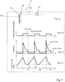
- FIG 7 shows how the disadvantageous build-up of an ever-increasing overpressure in the system with the negative effects in terms of a non-uniform droplet size is avoided by the measures according to the invention as described above.
- Partial figure 7a shows schematically and by way of example an application system 17 with a print head 18 which has thirty-two coating agent nozzles 19, a valve 20 being attached to each coating agent nozzle 19 and assigned to it.
- the coating medium supply line 22 there is a pump 21 which pumps the coating medium through the coating medium supply line 22 to the print head 18 at a constant flow rate.
- the pump 21 can be designed, for example, as a gear pump or as a piston pump, both types of pumps that can generate a constant flow rate even with varying pressure.
- the partial figures 7b -7d show the time curves of the valve position ( Figure 7b ), the flow of coating agent at the nozzle outlet opening of a coating agent nozzle ( Figure 7c , solid line), the flow rate of the coating agent impressed by the pump 21 ( Figure 7c , dashed line) and the pressure at the coating agent nozzle 19 of the print head 18 ( Figure 7d ) during two complete switching periods T1 and T2 and half a switching period T3.
- the individual nozzle exit openings for the coating material usually have a diameter of approx. 10 ⁇ m to 200 ⁇ m.
- the individual nozzle outlet openings are due to manufacturing tolerances, wear and tear or deposits of a printhead are not completely identical.
- Each of the nozzle outlet openings controlled by a valve therefore has a different flow resistance.
- the print head is moved at a constant speed over the surface to be coated.
- the material properties, the layer thickness to be achieved and the distance between the outlet openings then result in an average paint flow rate, if paint is the coating agent, or an average coating agent flow rate.
- V ⁇ m ⁇ ⁇ i.e D v a f V
- the switching frequency or the time of a period (from opening of the valve to the next opening) T p and the time T v that the valve is open are empirical values.
- the aim is for the same quantity of coating material to flow through all nozzle outlet openings on average over time. This can be achieved by opening the individual valves for different lengths of time.
- the coating material is supplied via a dosing pump, for example, the following applies:
- a metering pump in a coating device is that the fluidic conditions in the entire application system are independent of the viscosity of the coating agent and therefore parameter values do not have to be set for the coating material used in each case
- the coating agent pressure or the paint pressure depends on how many valves are open. The fewer valves that are open, the higher the pressure. This means that the time differences between the individual valve switching times are lower than when operating with constant pressure.
Landscapes
- Coating Apparatus (AREA)
- Spray Control Apparatus (AREA)
Abstract
Description
- Die Erfindung betrifft ein Applikationssystem zum Beschichten von Bauteilen gemäß dem Oberbegriff des Anspruchs 1 sowie eine Beschichtungseinrichtung gemäß dem Oberbegriff das Anspruchs 2.
- Ein solches Applikationssystem umfasst folgende Baugruppen:
- ein Applikationsgerät, das das Beschichtungsmittel appliziert, wobei das Applikationsgerät ein Druckkopf ist, der das Beschichtungsmittel aus mehreren Beschichtungsmitteldüsen ausstößt, wobei an jeder einzelnen Beschichtungsmitteldüse ein Düsenventil angebracht ist, das sich eine Ventilöffnungszeit lang öffnet, wenn ein Beschichtungsmitteltropfen die jeweilige Düse verlassen soll,
- eine Beschichtungsmittelzuleitung, mit der die Beschichtungsmitteldüsen des Druckkopfes gemeinsam verbunden sind,
- eine Ventilsteuerung zur Steuerung der Ventilöffnungszeiten und Ventilschließzeiten jedes einzelnen Ventil.
- Eine Beschichtungseinrichtung umfasst einen Roboter, an dem wenigstens das Applikationsgerät aufgenommen ist. Üblicherweise ist das Applikationsgerät an dem Roboter an dem sogenannten Tool Center Point, kurz TCP, aufgenommen.
- Die
DE 10 2008 053 178 A1 zeigt eine Beschichtungseinrichtung zur Beschichtung, insbesondere Lackierung von Kraftfahrzeugkarosseriebauteilen. Bei einer solchen Lackieranlage zur Lackierung von Kraftfahrzeugkarosseriebauteilen werden die zu lackierenden Kraftfahrzeugkarosseriebauteile auf einem durch eine Lackierkabine transportiert, in der die Kraftfahrzeugkarosseriebauteile dann von Lackierrobotern lackiert werden. Die Lackierroboter weisen einen oder mehrere schwenkbare Roboterarme auf und führen über eine mehrachsige Roboterhandachse an ihrem TCP jeweils ein Applikationsgerät. Das Applikationsgerät ist hier als ein Druckkopf ausgeführt, der das Beschichtungsmittel aus mehreren Beschichtungsmitteldüsen ausstößt, und die Beschichtungsmitteldüsen des Druckkopfes sind gemeinsam mit einer Beschichtungsmittelzuleitung verbunden, über die das zu applizierende Beschichtungsmittel zugeführt wird. Die Lackierung mittels eines solchen Druckkopfes ist vorteilhaft, wenn beispielsweise eine Fahrzeugkarosserie mehrfarbig lackiert werden soll, wenn an verschiedenen Stellen an der Karosserie unterschiedliche Farben aufgebracht werden sollen. Die Lackierung mit einem Druckkopf-Applikator ermöglicht das randscharfe Lackieren unterschiedlicher Zonen auf dem Werkstück, also z.B. der Karosserie, ohne weitere zusätzliche Vorkehrungen, insbesondere ohne Abkleben andersfarbiger Bereiche. - Die Dosierung des Beschichtungsmaterials bei der Lackierung mit einem Druckkopf-Applikator erfolgt üblicherweise mittels eines Druckreglers für das Beschichtungsmaterial. Diese Dosierung mittels eines Druckreglers hat einige Nachteile, insbesondere bei der Lackierung von Automobilkarosserien oder Karosserieteilen in einer Automobil-Lackierstraße. Die Durchflussrate eines bei der Automobillackierung verwendeten Lackes als Beschichtungsmaterial hängt nämlich von der Viskosität und vom Druck ab. Die Viskosität des Beschichtungsmaterials kann sich bei unterschiedlichen Lackmaterialien zum Teil stark unterscheiden. Manche benutzten Lackiermaterialien sind thixotrop, das heißt sie haben eine druckabhängige Viskosität. Diese erhebliche Abhängigkeit der Viskosität des Beschichtungsmittels von der Materialart und vom Druck führt oft zu ungleichförmiger Tropfengröße während des Beschichtens und damit zu großen Schwierigkeiten, eine homogene Beschichtung zu gewährleisten.
- Es ist daher die der vorliegenden Erfindung zugrundeliegende Aufgabe, ein Applikationssystem der eingangs genannten Art so zu verbessern, dass eine zeitlich konstante Tropfengröße während des Beschichtungsvorganges sichergestellt ist.
- Weiter ist es eine Aufgabe der vorliegenden Erfindung, eine Beschichtungseinrichtung weiter zu verbessern.
- Diese Aufgabe wird bezüglich des Applikationssystems gelöst mit einem Applikationssystem mit den Merkmalen des Anspruchs 1. Bezüglich der Beschichtungseinrichtung wird die Aufgabe gelöst mit einer Beschichtungseinrichtung mit den Merkmalen des Anspruchs 4.
- Erfindungsgemäß umfasst das Applikationssystem weiter eine Pumpe, mittels der das zu applizierende Beschichtungsmittel über die Beschichtungsmittelzuleitung den Beschichtungsmitteldüsen zugeführt wird, und das Applikationssystem ist so eingerichtet, dass die Pumpe während des Beschichtens mit einer konstanten Durchflussrate des Beschichtungsmittels arbeitet, und dass der Druck an jeder Düse bei einem Öffnen des Ventils genau so groß ist wie beim vorhergehenden Öffnen dieses Ventils.
- Gemäß der Erfindung hat das Applikationssystem eine Beschichtungsmittelrückleitung, in der ein Rückführventil eingebaut ist, welches wenigstens dann öffnet wenn die Düsenventile des Druckkopfes gleichzeitig geschlossen sind.
- Alternativ ist die Ventilsteuerung dazu eingerichtet, dass während des Beschichtens immer eine gleich bleibende Anzahl an Düsenventilen eines Druckkopfes geöffnet ist.
- Die Erfindung sowie weitere Ausführungsformen und weitere Vorteile der Erfindung werden nun im Zusammenhang mit der folgenden Figurenbeschreibung erläutert und beschrieben.
- Es zeigen:
- Figur 1
- schematisch und exemplarisch einen Druckkopf zur Verwendung in einem erfindungsgemäßen Applikationsgerät, mit hier exemplarisch dargestellten zehn Beschichtungsmitteldüsen, angeordnet in einer Linie hintereinander, wobei die Linie sich in etwa senkrecht zur Bewegungsrichtung des Applikationsgerätes beim Beschichten erstreckt,
- Figur 2
- schematisch und exemplarisch einen Druckkopf mit zweiunddreißig Beschichtungsmitteldüsen, wobei an jeder Beschichtungsmitteldüse ein Ventil angebracht ist, und die Beschichtungsmitteldüsen gemeinsam mit einer Beschichtungsmittelzuleitung verbunden sind, in zwei Ausführungsformen: links mit Beschichtungsmittelzuführung von einer Seite, rechts mit Beschichtungsmittelzuführung von zwei Seiten,
- Figur 3
- schematisch und exemplarisch eine Ausführungsform eines Applikationssystems, bei dem drei Druckköpfe mit jeweils zweiunddreißig Beschichtungsmitteldüsen aneinandergereiht sind, um die Beschichtungsleistung zu erhöhen, und bei dem die Beschichtungsmitteldüsen in benachbarten Druckköpfen gegeneinander versetzt sind,
- Figur 4
- schematische Veranschaulichung eines Betriebsmodus der Beschichtungsmitteldüsen eines Druckkopfes, gemäß dem Stand der Technik,
- Figur 5a
- schematisch und exemplarisch ein Applikationssystem mit einem Drucckopf, der zweiunddreißig Beschichtungsmitteldüsen hat, wobei an jeder Beschichtungsmitteldüse ein Ventil angebracht und dieser zugeordnet ist;
- Figur 5b
- den zeitlichen Verlauf der Ventilstellung während zweier vollständiger Schaltperioden T1 und T2 sowie einer halben Schaltperiode T3,
- Figur 5c
- den zeitlichen Verlauf des Beschichtungsmittelflusses an der Düsenaustrittsöffnung einer Beschichtungsmitteldüse (durchgezogene Linie), und der von der Pumpe eingeprägten Durchflussrate des Beschichtungsmittels (gestrichelte Linie)
- Figur 5d
- den zeitlichen Verlauf des Druckes an der Beschichtungsmitteldüse des Druckkopfes,
- Figur 6a
- eine Ausführungsform entsprechend der in
Figur 5a dargestellten, bei der zusätzlich eine Beschichtungsmittel-Rückleitung vorhanden ist, in der ein Rückführventil eingebaut ist. - Figur 6b
- die Schaltzustände der Düsenventile gemäß
Figur 6a während zweier vollständiger Schaltperioden T1 und T2 sowie einer halben Schaltperiode T3, - Figur 6c
- den zu den Schaltzuständen der Düsenventile nach
Figur 6b korrespondierenden Schaltzustand des Rückführventils, während zweier vollständiger Schaltperioden T1 und T2 sowie einer halben Schaltperiode T3. - Figur 7
- wie durch die erfindungsgemäßen Maßnahmen der nachteilige Aufbau eines immer weiter ansteigenden Überdrucks im System mit den negativen Auswirkungen hinsichtlich einer nicht-uniformen Tropfengröße vermieden ist,
- Figur 8a
- schematisch und exemplarisch ein Applikationssystem mit einem Drucckopf, der zweiunddreißig Beschichtungsmitteldüsen hat, wobei an jeder Beschichtungsmitteldüse ein Ventil angebracht und dieser zugeordnet ist.
- Figur 8b
- schematisch und exemplarisch den Betriebsmodus der Beschichtungsmitteldüsen des Druckkopfes aus
Figur 8a mit den zweiunddreißig Beschichtungsmitteldüsen 1 - 32, - Figur 9
- einen beispielhaften Betriebsmodus für ein Applikationssystem mit drei Druckköpfen, von denen jeder zweiunddreißig Ventile hat.
-
Figur 1 zeigt schematisch und exemplarisch einen Druckkopf 1 zur Verwendung in einem erfindungsgemäßen Applikationsgerät. Hier ist der Druckkopf 1 schematisch und exemplarisch als eine quaderförmige Struktur dargestellt. Er hat hier im Beispiel zehn Beschichtungsmitteldüsen 2, die an einer Schmalseite des Druckkopfes in einer Linie hintereinander angeordnet sind, wobei die Linie sich in etwa senkrecht zur Bewegungsrichtung des Applikationsgerätes beim Beschichten erstreckt, siehe hierzuFigur 3 . Der Pfeil D zeigt die Richtung des Ausstoßes der Beschichtungsmitteltropfen an. -
Figur 2 zeigt schematisch und exemplarisch einen Druckkopf 3 mit zweiunddreißig Beschichtungsmitteldüsen 4, die im Wesentlichen baugleich sind zu den Beschichtungsmitteldüsen2 gemäß der inFigur 1 gezeigten Ausführungsform. An jeder Beschichtungsmitteldüse 4 ist ein Ventil 5 angebracht, und die Beschichtungsmitteldüsen 4 sind gemeinsam mit einer Beschichtungsmittelzuleitung 6 verbunden. Die Ventile können mit einer Schaltfrequenz im Bereich einiger kHz geschaltet werden, typischerweise im Bereich von 3 kHz. Links inFigur 2 ist eine Ausführungsform gezeigt, bei der das Beschichtungsmittel nur von einer Seite, hier von oben, zugeführt wird. Rechts in derFigur 2 ist eine Ausführungsform gezeigt, bei der das Beschichtungsmittel von zwei Seiten, hier von oben und unten, zugeführt wird, wobei sich dazu die Beschichtungsmittelzuleitung 6 in einen oberen und einen unteren Teilarm 7, 8 aufteilt. -
Figur 3 zeigt schematisch und exemplarisch eine Ausführungsform eines Applikationssystems 9, bei dem drei Druckköpfe 10, 11, 12 mit jeweils zweiunddreißig Beschichtungsmitteldüsen 13 aneinandergereiht sind, um die Beschichtungsleistung zu erhöhen. Die Bewegungsrichtung des Applikationssystems 9 während der Beschichtung ist durch den Pfeil P angedeutet, man sieht dass diese in etwa senkrecht zu der Linie verläuft, in der die Beschichtungsmitteldüsen 13 in jeden der drei Druckköpfe 10, 11, 12 angeordnet sind. Der Abstand zwischen benachbarten Beschichtungsmitteldüsen 13 ist mit a bezeichnet. Dieser Abstand kann aus konstruktiven Gründen nicht beliebig klein gemacht werden. Um einen gleichmäßigen Auftrag des Beschichtungsmittels zu erreichen, sind die Beschichtungsmitteldüsen 13 der drei aneinander gereihten Druckköpfe 10, 11, 12 um jeweils einen Betrag von a/3 gegeneinander versetzt angeordnet, wie in der im rechten Teil derFigur 3 dargestellten Ausschnittsvergrößerung eines Teilbereiches 14 des Beschichtungsmitteldüsenfeldes dargestellt ist. -
Figur 4 zeigt schematisch und exemplarisch den Betriebsmodus 16 der Beschichtungsmitteldüsen eines Druckkopfes, wie er gemäß dem Stand der Technik üblicherweise angewendet wird. Für die exemplarische Erläuterung ist hier ein Drucckopf 15 mit sechs Betriebsmitteldüsen D1 - D6 angenommen. Die waagerecht verlaufenden Balken, mit den abwechselnd schwarzen und weißen Feldern, zeigen den Schaltzustand der jeweiligen Ventile an, wenn der Druckkopf 15 zum Beschichten bewegt wird. Ein dunkles Feld zeigt an, dass das entsprechende Ventil in dieser Zeit offen ist, während dieser Zeit tritt ein Beschichtungsmitteltropfen aus der jeweiligen düse aus. Ein helles Feld zeigt an, dass das entsprechende Ventil während dieser Zeit geschlossen ist, während dieser Zeit tritt kein Beschichtungsmitteltropfen durch die entsprechende Düse aus. Bei dem üblichen Betriebsmodus 16, wie er in der Figur 4 veranschaulicht ist, werden alle Ventile gleichzeitig geöffnet und geschlossen. Man macht das oft, um eine scharfe Anfangs- und Endlinie der Beschichtung zu bekommen. In derFigur 4 sind insgesamt acht Schaltperioden T1 - T8 in ihrer zeitlich hintereinanderliegenden Reihenfolge aneinander gereiht dargestellt. -
Figur 5 zeigt in der Teilfigur 5a schematisch und exemplarisch ein Applikationssystem 17, mit einem Druckkopf 18, der zweiunddreißig Beschichtungsmitteldüsen 19 hat, wobei an jeder Beschichtungsmitteldüse 19 ein Ventil 20 angebracht und dieser zugeordnet ist. In der Beschichtungsmittelzuleitung 22 befindet sich eine Pumpe 21, die das Beschichtungsmittel mit einer konstanten Durchflußrate durch die Beschichtungsmittelzuleitung 22 zu dem Druckkopf 18 pumpt. Die Pumpe 21 kann beispielsweise als Zahnradpumpe oder als Kolbenpumpe ausgebildet sein, beides Pumpenarten, die eine konstante Durchflussrate auch bei variierendem Druck erzeugen können. Die Teilfiguren 5b -5d zeigen die zeitlichen Verläufe der Ventilstellung (Fig. 5b ), des Beschichtungsmittelflusses an der Düsenaustrittsöffnung einer Beschichtungsmitteldüse (Figur 5c , durchgezogene Linie), der von der Pumpe 21 eingeprägten Durchflussrate des Beschichtungsmittels (Figur 5c , gestrichelte Linie) und des Druckes an der Beschichtungsmitteldüse 19 des Druckkopfes 18 (Figur 5d ) während zweier vollständiger Schaltperioden T1 und T2 sowie einer halben Schaltperiode T3. Wenn die Ventile alle gleichzeitig geschlossen sind, beispielsweise in der Schaltperiode T1 zum Zeitpunkt A, pumpt die Pumpe 21 weiter mit konstanter Durchflussrate das Beschichtungsmittel in das Applikationssystem 17. Der Druck im Applikationssystem und damit der Druck an der Beschichtungsmitteldüse des Druckkopfes steigt an, es entsteht ein Überdruck im Applikationssystem, sieheFig. 5d , da die Schläuche und andere Komponenten des Applikationssystems eine gewisse Elastizität haben. Wenn nun das Ventil zu Beginn des folgenden Schaltzyklus wieder geöffnet wird, siehe beispielsweise Zeitpunkt B zu Beginn des Schaltzyklus T2, fällt der Druck wieder ab und nach einer kurzen Zeit ist der Beschichtungsmittelfluss an der Austrittsöffnung der Beschichtungsmitteldüse konstant. - In der vorliegenden Erfindung wurde überraschend erkannt, dass unter bestimmten Umständen, wenn die Zeitkonstanten des Applikationssystems so groß sind, dass ein vollständiger Abbau des Überdruckes bis zum Beginn der nächsten folgenden Schaltperiode nicht möglich ist, sich der Überdruck während der nächsten Schaltperiode dann von einem höheren Ausgangspunkt aus weiter erhöht, und so fort, so dass der Druck im Applikationssystem immer weiter ansteigt. Da die Flussrate des Beschichtungsmittels an der Austrittsdüse des Druckkopfes neben der Viskosität auch vom Druck abhängt, ergibt sich daraus das überraschend erkannte Problem, dass obwohl die Pumpe eine konstante Durchflussrate erzeugt, die Durchflussrate an der Austrittsöffnung der Beschichtungsmitteldüse und damit die Tropfengröße nicht uniform gleich groß ist, sondern sich mit der Zeit ändert. Das ist im Hinblick auf ein optimales Beschichtungsergebnis nachteilig.
-
Figur 6 zeigt eine erste Lösung für dieses überraschend erkannte Problem. In der Teilfigur 6a ist eine Ausführungsform entsprechend der inFigur 5a dargestellten gezeigt, bei der zusätzlich eine Beschichtungsmittel-Rückleitung 23 vorhanden ist, in der ein Rückführventil 24 eingebaut ist. Eine Ventilsteuerung 25 steuert die Düsenventile 20 im Druckkopf und das Rückführventil 25.Figur 6b zeigt die Schaltzustände der Düsenventile 20 undFigur 6c zeigt den dazu korrespondierenden Schaltzustand des Rückführventils 24, jeweils während zweier vollständiger Schaltperioden T1 und T2 sowie einer halben Schaltperiode T3. Das Rückführventil 24 ist geöffnet wenn die Düsenventile 20 geschlossen sind, und es ist geschlossen, wenn die Düsenventile 20 geöffnet sind. Wenn die Düsenventile 20 geschlossen sind, pumpt die Pumpe 21 das Beschichtungsmittel über das geöffnete Rückführventil 24 und die Beschichtungsmittelrückleitung 23 im Kreislauf. Im Ergebnis wird durch diese Maßnahme erreicht, dass nunmehr ein vollständiger Abbau des Überdruckes bis zum Beginn der einem Schließen aller Düsenventile 20 nächsten folgenden Schaltperiode erfolgt, sich somit der Überdruck während der nächsten Schaltperiode dann wieder von dem Druckniveau aus erhöht, das zu Beginn des vorherigen Öffnens der Düsenventile 20 geherrscht hat, so dass nun der Druck im Applikationssystem nicht immer weiter ansteigt. Dadurch ist die Durchflussrate an der Austrittsöffnung der Beschichtungsmitteldüse und damit die Tropfengröße uniform gleich groß, sie ändert sich mit der Zeit nicht. Das ist im Hinblick auf ein optimales Beschichtungsergebnis von Vorteil. - Eine weitere Lösungsmöglichkeit besteht darin, dass die Ventilsteuerung dazu eingerichtet ist, dass während des Beschichtens immer eine gleich bleibende Anzahl an Düsenventilen eines Druckkopfes geöffnet ist.
Figur 8 veranschaulicht diese Lösung beispielhaft und exemplarisch. Die Teilfigur 8a zeigt schematisch und exemplarisch ein Applikationssystem 17, mit einem Druckkopf 18, der zweiunddreißig Beschichtungsmitteldüsen 19 hat, wobei an jeder Beschichtungsmitteldüse 19 ein Ventil 20 angebracht und dieser zugeordnet ist. In der Beschichtungsmittelzuleitung 22 befindet sich eine Pumpe 21, die das Beschichtungsmittel mit einer konstanten Durchflußrate durch die Beschichtungsmittelzuleitung 22 zu dem Druckkopf 18 pumpt. Die Pumpe 21 kann beispielsweise als Zahnradpumpe oder als Kolbenpumpe ausgebildet sein, beides Pumpenarten, die eine konstante Durchflussrate auch bei variierendem Druck erzeugen können. -
Figur 8b zeigt schematisch und exemplarisch den Betriebsmodus 26 der Beschichtungsmitteldüsen des Druckkopfes 18 ausFigur 8a mit den zweiunddreißig Beschichtungsmitteldüsen 1 - 32 gemäß der hier beschriebenen zweiten erfindungsgemäßen Lösung. Die waagerecht verlaufenden Balken, mit den abwechselnd schwarzen und weißen Feldern, zeigen den Schaltzustand der jeweiligen Ventile an, wenn der Druckkopf 18 zum Beschichten bewegt wird. Ein dunkles Feld zeigt an, dass das entsprechende Ventil in dieser Zeit offen ist, während dieser Zeit tritt ein Beschichtungsmitteltropfen aus der jeweiligen Düse aus. Ein helles Feld zeigt an, dass das entsprechende Ventil während dieser Zeit geschlossen ist, während dieser Zeit tritt kein Beschichtungsmitteltropfen durch die entsprechende Düse aus. Die Ventilsteuerung sorgt dafür, dass die Schaltreihenfolge der Ventile 20 so eingestellt ist, dass immer eine konstante Anzahl an Ventilen offen ist. InFigur 8b sind zehn aufeinanderfolgende Schaltperioden A - J dargestellt. Während des ersten Teils der ersten Schaltperiode A sind acht Ventile offen, die Nr. 1, 2, 3, 4, 29, 30, 31, 32. Die übrigen vierundzwanzig Ventile sind geschlossen, Wenn die acht Ventile Nr. 1, 2, 3, 4, 29, 30, 31, 32 schließen, öffnen die acht Ventile Nr. 5, 6, 7, 8, 25, 26, 27, 28. Am Ende der ersten Schaltperiode A und zu Beginn der zweiten Schaltperiode B schließen die Ventile Nr. 5, 6, 7, 8, 25, 26, 27, 28 wieder, die Ventile Nr. 1, 2, 3, 4, 29, 30, 31, 32 bleiben geschlossen, und es öffnen die acht Ventile Nr. 9, 10, 11, 12, 21, 22, 23, 24. Wenn diese in der Mitte der zweiten Schaltperiode B wieder schließen, öffnen die acht Ventile 13, 14, 15, 16, 17, 18, 19, 20. Die übrigen Ventile bleiben bis zum Ende der zweiten Schaltperiode B und Beginn der dritten Schaltperiode C geschlossen. Danach wiederholt sich dieses Schema. Es sind bei diesem Schema immer acht Ventile offen und 24 Ventile geschlossen, das Schaltschema stellt dabei sicher, dass innerhalb von zwei Schaltperioden jedes der zweiunddreißig Ventile einmal geöffnet hat. Die Pumpe arbeitet immer mit konstanter Durchflussrate des Beschichtungsmittels. Es kann sich kein ansteigender Überdruck im System aufbauen, weil immer acht Ventile geöffnet sind. Bei einer typischen Ventilöffnungszeit von 1 ms und einer angenommenen, beispielhaften Geschwindigkeit von 200mm/s des Roboterarms beim Beschichten ist die Wegstrecke, die der Druckkopf während zweier Schaltperioden zurücklegt, bis also wieder dieselben acht Ventile öffnen wir zu Beginn, 0,8 mm. Neben dem in derFigur 8 dargestellten Schaltschema sind noch viele weitere denkbar. So könnten beispielsweise nicht nur acht, sondern etwa auch sechzehn oder auch nur vier Ventile gleichzeitig geöffnet sein. Auch kann die Verteilung der geöffneten Ventile längs der Linie, an der sie angeordnet sind, variieren. Wichtig ist nur, dass immer eine gleiche Anzahl an Ventilen geöffnet ist. - Das in
Figur 8 anhand eines Druckkopfes gezeigte Vorgehen lässt sich auch übertragen auf ein Applikationssystem mit mehreren Druckköpfen.Figur 9 zeigt das beispielhaft anhand eines beispielhaften Betriebsmodus 27 für ein Applikationssystem mit drei Druckköpfen, von denen jeder zweiunddreißig Ventile hat. Auch hier zeigen die waagerecht verlaufenden Balken, mit den abwechselnd schwarzen bzw. schraffierten und weißen Feldern den Schaltzustand der jeweiligen Ventile an, wenn der Druckkopf zum Beschichten bewegt wird. Ein dunkles bzw. schraffiertes Feld zeigt an, dass das entsprechende Ventil in dieser Zeit offen ist, während dieser Zeit tritt ein Beschichtungsmitteltropfen aus der jeweiligen Düse aus. Ein helles Feld zeigt an, dass das entsprechende Ventil während dieser Zeit geschlossen ist, während dieser Zeit tritt kein Beschichtungsmitteltropfen durch die entsprechende Düse aus. Die Balken mit den schwarz gefüllten Feldern zur Anzeige eines geöffneten Ventils sind dem ersten Druckkopf zugeordnet. Die Balken mit den schräg schraffierten Feldern zur Anzeige eines geöffneten Ventils sind dem zweiten Druckkopf zugeordnet. Die Balken mit den senkrecht schraffierten Feldern zur Anzeige eines geöffneten Ventils sind dem dritten Druckkopf zugeordnet. Auch hier ist sichergestellt, dass an jedem der drei Druckköpfe immer acht der zweiunddreißig Ventile geöffnet sind. Da drei Druckköpfe parallel betrieben werden, wird in jeder Schaltperiode aus mehr als acht Düsen Beschichtungsmittel ausgestoßen, und zwar je nach Schaltperiode aus sechzehn oder vierundzwanzig Beschichtungsmitteldüsen. Auf diese Weise kann eine noch bessere Schichthomogenität erzielt werden. -
Figur 7 zeigt, wie durch die erfindungsgemäßen Maßnahmen wie oben beschrieben der nachteilige Aufbau eines immer weiter ansteigenden Überdrucks im System mit den negativen Auswirkungen hinsichtlich einer nicht-uniformen Tropfengröße vermieden ist. Teilfigur 7a zeigt schematisch und exemplarisch ein Applikationssystem 17, mit einem Druckkopf 18, der zweiunddreißig Beschichtungsmitteldüsen 19 hat, wobei an jeder Beschichtungsmitteldüse 19 ein Ventil 20 angebracht und dieser zugeordnet ist. In der Beschichtungsmittelzuleitung 22 befindet sich eine Pumpe 21, die das Beschichtungsmittel mit einer konstanten Durchflußrate durch die Beschichtungsmittelzuleitung 22 zu dem Druckkopf 18 pumpt. Die Pumpe 21 kann beispielsweise als Zahnradpumpe oder als Kolbenpumpe ausgebildet sein, beides Pumpenarten, die eine konstante Durchflussrate auch bei variierendem Druck erzeugen können. Nicht dargestellt ist inFigur 7a die Beschichtungsmittelrückleitung mit dem Rückführventil. Die Teilfiguren 7b -7d zeigen die zeitlichen Verläufe der Ventilstellung (Fig. 7b ), des Beschichtungsmittelflusses an der Düsenaustrittsöffnung einer Beschichtungsmitteldüse (Figur 7c , durchgezogene Linie), der von der Pumpe 21 eingeprägten Durchflussrate des Beschichtungsmittels (Figur 7c , gestrichelte Linie) und des Druckes an der Beschichtungsmitteldüse 19 des Druckkopfes 18 (Figur 7d ) während zweier vollständiger Schaltperioden T1 und T2 sowie einer halben Schaltperiode T3. Im Unterschied zu den inFigur 5b bis 5d erläuterten Zusammenhängen ist nun, nach Einsetzten einer der erfindungsgemäßen Maßnahmen, erreicht, dass ein vollständiger Abbau des Überdruckes bis zum Beginn der nächsten folgenden Schaltperiode erfolgt ist, und der Überdruck während der nächsten Schaltperiode dann von demselben Ausgangsdruck aus wieder erhöht, wie er zu Beginn der vorhergehenden Schaltperiode geherrscht hat und so fort, so dass der Druck im Applikationssystem nicht immer weiter ansteigt. - Ergänzende Erläuterungen:
Die einzelnen Düsenaustrittsöffungen für das Beschichtungsmaterial haben in der Regel einen Durchmesser von ca. 10µm bis 200 µm. Bedingt durch Fertigungstoleranzen, Verschleiß bzw. Ablagerungen sind die einzelnen Düsenaustrittsöffnungen eines Druckkopfes nicht komplett identisch. - Jede der mit einem Ventil angesteuerten Düsenaustrittsöffnungen hat daher einen unterschiedlichen Strömungswiderstand. Die durch die Düsenaustrittsöffnung i fließende Materialmenge V̇i ist abhängig vom Druck vor der Austrittsöffnung pi . Dieser Zusammenhang wird beschrieben durch die Funktion V̇i = fi (pi ) bzw. die Umkehrfunktion pi = gi (V̇i ).
- Bei der konstruktiven Ausgestaltung eines Druckkopfes wird darauf geachtet, dass der Druck an allen Düsenaustrittsöffnungen immer gleich ist, d.h. der Druckabfall in der Beschichtungsmittelzuleitung sollte vernachlässigbar sein.
- Zu beachten ist, dass die Funktionen fi bzw. gi von der Viskosität und damit vom applizierten Beschichtungsmaterial abhängen.
- In erster Näherung kann man davon ausgehen, dass die oben beschriebenen Funktionen im interessierenden Bereich linear sind. Die Gleichung für die Düsenaustrittsöffnung ist

- Der Druckkopf wird mit konstanter Geschwindigkeit über die zu beschichtende Oberfläche bewegt. Aus den Materialeigenschaften, der zu erreichenden Schichtdicke und den Abstand zwischen den Austrittsöffnungen ergibt sich dann eine mittlere Lackflussrate, im Fall dass Lack das Beschichtungsmittel ist, bzw. eine mittlere Beschichtungsmittelflussrate.

- Mit
- V̇ m
- mittlere Lackflussrate pro Düse
- dD
- Abstand zwischen den Düsen senkrecht zur Bewegungsrichtung (bei mehreren hintereinander angeordneten Applikatoren resultierender Abstand) µ Schichtdicke (Trockenfilm)
- fV
- Volumenfeststoffgehalt des applizierten Materials
- va
- Geschwindigkeit des Applikators (TCP Geschwindigkeit)
- Die Schaltfrequenz bzw. die Zeit einer Periode (von Öffnen des Ventils bis zum nächsten Öffnen) Tp und die Zeit Tv, die das Ventil geöffnet ist, sind Erfahrungswerte.
- Die Lackflussrate durch eine Düsenaustrittsöffnung ist durch folgenden Zusammenhang näherungsweise beschrieben:

- Das Volumen des bei einer Ventilöffnung ausgestoßenen Beschichtungsmittel (Tropfenvolumen) ist durch folgenden Zusammenhang beschrieben:

- Ziel im Hinblick auf eine homogene Beschichtung ist es, dass durch alle Düsenaustrittsöffnungen im zeitlichen Mittel die gleiche Menge an Beschichtungsmaterial fließt. Das kann dadurch erreicht werden, dass die einzelnen Ventile unterschiedlich lang geöffnet sind.
- Die Vorgehensweise für den Fall, dass der Druckabfall in der Verteilungsleitung vernachlässigbar ist, ist dann die folgende.
- Im ersten Schritt wird für jede Austrittöffnung die Kennlinie V̇i = fi (p) bzw. pi = g(V̇i ). ermittelt.
- Im Falle der oben beschriebenen Linearität erhält man die Kennwerte ki...kn mit

- Für die Variante der Beschichtungsmaterialversorgung mit einem Materialdruckregler gilt folgendes:
- Vorgabewert:
- Lackmenge pro Ventilöffnung mittlere Ventilöffnungszeit
- Der am Materialdruckregler einzustellende Materialdruck und die Ventilöffnungszeit ergeben sich zu:


- Für den Fall der Beschichtungsmaterialversorgung über beispielsweise eine Dosierpumpe gilt folgendes:
Der Vorteil der Verwendung einer Dosierpumpe in einer Beschichtungseinrichtung ist, dass die fluidischen Verhältnisse in dem gesamte Appliaktionsystem unabhängig von der Viskosität des Beschichtungsmittels sind und damit keine Einstellung von Parameterwerten auf das jeweils verwendete Beschichtungsmaterial Material erfolgen muss - Da die Pumpe die gesamte Zeit mit der gleichen Beschichtungsmittelrate, im Falle dass Lack das Beschichtungsmittel ist also mit einer konstanten Lackflussrate, arbeitet, ist der Beschichtungsmitteldruck bzw. der Lackdruck davon abhängig, wieviel Ventile geöffnet sind. Je weniger Ventile geöffnet sind, desto höher der Druck. Damit sind die Zeitdiffrenzen zwischen den einzelnen Ventilschaltzeiten geringer als beim Betrieb mit konstanten Druck.
Bezugszeichenliste 1 Druckkopf 2 Beschichtungsm itteldüse 3 Druckkopf 4 Beschichtungsm itteldüse 5 Ventil 6 Beschichtungsm ittelzuleitung 7 Teilarm 8 Teilarm 9 Applikationssystem 10 Druckkopf 11 Druckkopf 12 Druckkopf 13 Beschichtungsm itteldüse 14 Teilbereich 15 Druckkopf 16 Schema eines Betriebsmodus 17 Applikationssystem 18 Druckkopf 19 Beschichtungsm itteldüse 20 Ventil 21 Pumpe 22 Beschichtungsmittelzuleitung 23 Beschichtungsm ittelrückleitung 24 Rückführventil 25 Ventilsteuerung 26 Betriebsmodus 27 Betriebsmodus
Claims (2)
- Applikationssystem zum Beschichten von Bauteilen mit einem Beschichtungsmittel, welches folgende Baugruppen umfasst:- ein Applikationsgerät, das das Beschichtungsmittel appliziert, wobei das Applikationsgerät ein Druckkopf (1, 3) ist, der das Beschichtungsmittel aus mehreren Beschichtungsmitteldüsen (2, 4, 19) ausstößt, wobei an jeder einzelnen Beschichtungsmitteldüse (2) ein Düsenventil (5, 20) angebracht ist, das sich eine Ventilöffnungszeit lang öffnet, wenn ein Beschichtungsmitteltropfen die jeweilige Düse (4) verlassen soll,- eine Beschichtungsmittelzuleitung (6, 22), mit der die Beschichtungsmitteldüsen (4) des Druckkopfes (3) gemeinsam verbunden sind,- eine Ventilsteuerung (25) zur Steuerung der Ventilöffnungszeiten und Ventilschließzeiten jedes einzelnen Ventils (20),
dadurch gekennzeichnet, dass das Applikationssystem weiter eine Pumpe (21) umfasst, mittels der das zu applizierende Beschichtungsmittel über die Beschichtungsmittelzuleitung (22) den Beschichtungsmitteldüsen (19) zugeführt wird, und dass das Applikationssystem eingerichtet ist, dass die Pumpe (21) während des Beschichtens mit einer konstanten Durchflussrate des Beschichtungsmittels arbeitet, und dass der Druck an jeder Düse (19) bei einem Öffnen des Ventils (20) genau so groß ist wie beim vorhergehenden Öffnen dieses Ventils (20); wobei das Applikationssystem eine Beschichtungsmittelrückleitung (23) hat, in der ein Rückführventil (24) eingebaut ist, welches wenigstens dann öffnet wenn die Düsenventile (20) des Druckkopfes (18) gleichzeitig geschlossen sind. - Beschichtungseinrichtung zum Beschichten von Bauteilen mit einem Beschichtungsmittel, mit einem Applikationssystem gemäß Anspruch 1, wobei die Beschichtungseinrichtung einen Roboter umfasst, an dem wenigstens das Applikationsgerät aufgenommen ist.
Applications Claiming Priority (3)
| Application Number | Priority Date | Filing Date | Title |
|---|---|---|---|
| DE102017101937.5A DE102017101937A1 (de) | 2017-02-01 | 2017-02-01 | Applikationssystem zum Beschichten von Bauteilen und Beschichtungseinrichtung |
| EP18700646.5A EP3576884B1 (de) | 2017-02-01 | 2018-01-10 | Applikationssystem zum beschichten von bauteilen und beschichtungseinrichtung |
| PCT/EP2018/050491 WO2018141511A1 (de) | 2017-02-01 | 2018-01-10 | Applikationssystem zum beschichten von bauteilen und beschichtungseinrichtung |
Related Parent Applications (2)
| Application Number | Title | Priority Date | Filing Date |
|---|---|---|---|
| EP18700646.5A Division EP3576884B1 (de) | 2017-02-01 | 2018-01-10 | Applikationssystem zum beschichten von bauteilen und beschichtungseinrichtung |
| EP18700646.5A Division-Into EP3576884B1 (de) | 2017-02-01 | 2018-01-10 | Applikationssystem zum beschichten von bauteilen und beschichtungseinrichtung |
Publications (2)
| Publication Number | Publication Date |
|---|---|
| EP3957404A1 true EP3957404A1 (de) | 2022-02-23 |
| EP3957404B1 EP3957404B1 (de) | 2025-03-05 |
Family
ID=61002997
Family Applications (2)
| Application Number | Title | Priority Date | Filing Date |
|---|---|---|---|
| EP18700646.5A Active EP3576884B1 (de) | 2017-02-01 | 2018-01-10 | Applikationssystem zum beschichten von bauteilen und beschichtungseinrichtung |
| EP21201268.6A Active EP3957404B1 (de) | 2017-02-01 | 2018-01-10 | Applikationssystem zum beschichten von bauteilen und beschichtungseinrichtung |
Family Applications Before (1)
| Application Number | Title | Priority Date | Filing Date |
|---|---|---|---|
| EP18700646.5A Active EP3576884B1 (de) | 2017-02-01 | 2018-01-10 | Applikationssystem zum beschichten von bauteilen und beschichtungseinrichtung |
Country Status (6)
| Country | Link |
|---|---|
| US (1) | US11524309B2 (de) |
| EP (2) | EP3576884B1 (de) |
| CN (1) | CN110248739B (de) |
| DE (1) | DE102017101937A1 (de) |
| ES (1) | ES3029058T3 (de) |
| WO (1) | WO2018141511A1 (de) |
Families Citing this family (7)
| Publication number | Priority date | Publication date | Assignee | Title |
|---|---|---|---|---|
| DE102017110316B4 (de) | 2017-05-12 | 2021-02-25 | Abb Schweiz Ag | Applikationsgerät zum Beschichten von Bauteilen mit einem Beschichtungsmittel |
| US12539525B2 (en) | 2017-11-30 | 2026-02-03 | Axalta Coating Systems Ip Co., Llc | Coating compositions for application utilizing a high transfer efficiency applicator and methods and systems thereof |
| KR102634160B1 (ko) | 2017-11-30 | 2024-02-06 | 악살타 코팅 시스템즈 게엠베하 | 고 전달 효율 어플리케이터를 활용하는 코팅 조성물의 적용을 위한 시스템, 코팅 층 및 상응하는 방법 |
| DE102019003844A1 (de) * | 2019-06-03 | 2020-12-03 | Burkhard Büstgens | Drop-on-Demand Beschichtung von Flächen |
| US12122932B2 (en) | 2020-05-29 | 2024-10-22 | Axalta Coating Systems Ip Co., Llc | Coating compositions for application utilizing a high transfer efficiency applicator and methods and systems thereof |
| JP6979546B1 (ja) * | 2021-10-08 | 2021-12-15 | アーベーベー・シュバイツ・アーゲーABB Schweiz AG | 塗装装置 |
| CN116594366B (zh) * | 2023-07-17 | 2023-09-19 | 苏州聚贝机械设计有限公司 | 一种机械设备的涂抹部件控制系统 |
Citations (5)
| Publication number | Priority date | Publication date | Assignee | Title |
|---|---|---|---|---|
| EP0138322A1 (de) * | 1983-08-19 | 1985-04-24 | A.B. Dick Company | Tintenventil für Markierungssysteme |
| DE102008053178A1 (de) | 2008-10-24 | 2010-05-12 | Dürr Systems GmbH | Beschichtungseinrichtung und zugehöriges Beschichtungsverfahren |
| US20120033003A1 (en) * | 2010-08-09 | 2012-02-09 | Fuji Xerox Co., Ltd. | Flow rate control device, liquid-droplet ejecting device, and computer readable medium |
| US20130286114A1 (en) * | 2012-04-26 | 2013-10-31 | Seiko Epson Corporation | Liquid ejecting apparatus |
| DE102014013158A1 (de) * | 2014-09-11 | 2016-03-17 | Burkhard Büstgens | Freistrahl-Einrichtung |
Family Cites Families (9)
| Publication number | Priority date | Publication date | Assignee | Title |
|---|---|---|---|---|
| US5602575A (en) * | 1988-11-05 | 1997-02-11 | Rea Elektronik Gmbh | Ink jet writing head |
| US5618347A (en) * | 1995-04-14 | 1997-04-08 | Kimberly-Clark Corporation | Apparatus for spraying adhesive |
| JP2003033687A (ja) * | 2001-07-24 | 2003-02-04 | Sekisui House Ltd | 塗料供給エアポンプの流量自動制御装置 |
| FI115992B (fi) * | 2002-04-19 | 2005-08-31 | Marioff Corp Oy | Menetelmä ja laitteisto suihkutuslaitteiston ohjaamiseksi |
| JP5488052B2 (ja) * | 2010-03-01 | 2014-05-14 | セイコーエプソン株式会社 | 液体噴射装置 |
| DE102012005087A1 (de) * | 2011-03-28 | 2012-10-04 | Heidelberger Druckmaschinen Aktiengesellschaft | Vorrichtung zum Bedrucken von Oberflächen mit mehreren, bewegbaren Druckköpfen |
| DE112013001593B4 (de) * | 2012-03-22 | 2022-11-10 | Kabushiki Kaisha Yaskawa Denki | Applikationsvorrichtung |
| JP6252434B2 (ja) * | 2014-10-28 | 2017-12-27 | トヨタ自動車株式会社 | 間欠塗工装置の弁体制御方法 |
| DE102016014956A1 (de) * | 2016-12-14 | 2018-06-14 | Dürr Systems Ag | Beschichtungseinrichtung und zugehöriges Betriebsverfahren |
-
2017
- 2017-02-01 DE DE102017101937.5A patent/DE102017101937A1/de not_active Withdrawn
-
2018
- 2018-01-10 WO PCT/EP2018/050491 patent/WO2018141511A1/de not_active Ceased
- 2018-01-10 EP EP18700646.5A patent/EP3576884B1/de active Active
- 2018-01-10 ES ES21201268T patent/ES3029058T3/es active Active
- 2018-01-10 CN CN201880009784.0A patent/CN110248739B/zh active Active
- 2018-01-10 EP EP21201268.6A patent/EP3957404B1/de active Active
-
2019
- 2019-07-31 US US16/527,055 patent/US11524309B2/en active Active
Patent Citations (5)
| Publication number | Priority date | Publication date | Assignee | Title |
|---|---|---|---|---|
| EP0138322A1 (de) * | 1983-08-19 | 1985-04-24 | A.B. Dick Company | Tintenventil für Markierungssysteme |
| DE102008053178A1 (de) | 2008-10-24 | 2010-05-12 | Dürr Systems GmbH | Beschichtungseinrichtung und zugehöriges Beschichtungsverfahren |
| US20120033003A1 (en) * | 2010-08-09 | 2012-02-09 | Fuji Xerox Co., Ltd. | Flow rate control device, liquid-droplet ejecting device, and computer readable medium |
| US20130286114A1 (en) * | 2012-04-26 | 2013-10-31 | Seiko Epson Corporation | Liquid ejecting apparatus |
| DE102014013158A1 (de) * | 2014-09-11 | 2016-03-17 | Burkhard Büstgens | Freistrahl-Einrichtung |
Also Published As
| Publication number | Publication date |
|---|---|
| WO2018141511A1 (de) | 2018-08-09 |
| CN110248739A (zh) | 2019-09-17 |
| DE102017101937A1 (de) | 2018-08-02 |
| ES3029058T3 (en) | 2025-06-23 |
| CN110248739B (zh) | 2022-02-11 |
| EP3957404B1 (de) | 2025-03-05 |
| EP3576884B1 (de) | 2022-03-16 |
| US11524309B2 (en) | 2022-12-13 |
| EP3576884A1 (de) | 2019-12-11 |
| US20200023396A1 (en) | 2020-01-23 |
Similar Documents
| Publication | Publication Date | Title |
|---|---|---|
| EP3576884B1 (de) | Applikationssystem zum beschichten von bauteilen und beschichtungseinrichtung | |
| EP0021182B1 (de) | Verfahren und Vorrichtung zur Lackversorgung von Lackierstrassen | |
| EP1022137B1 (de) | Digitale Farbdosierung | |
| EP3444038B1 (de) | Spritzapparat und verfahren zum kühlen eines metallischen strangs in einer stranggiessmaschine | |
| DE3201930C2 (de) | Verfahren zum automatischen Aufbringen von Überzügen | |
| DE69719530T2 (de) | Sprühkopf sowie mit dem selben versehener sprühbalken | |
| WO1986001548A1 (fr) | Procede et dispositif pour appliquer une substance fluide | |
| DE69327315T2 (de) | Verfahren und vorrichtung zum auftragen von fluid, insbesondere von hot melt, auf ein substrat durch ein sequentielles auftragegerät | |
| EP1097812A2 (de) | Vorrichtung und Verfahren zum Befeuchten eines Bauteils in einer Druckmaschine | |
| DE19536623C1 (de) | Verfahren und Vorrichtung zum Dosieren von Dickstoffen | |
| EP1095707B1 (de) | Farbwechselventilanordnung und Verfahren zum Spülen eines Farbwechslers | |
| DE102010055019A1 (de) | Vorrichtung zum intermittierenden Auftragen eines flüssigen bis pastösen Mediums auf eine Auftragfläche | |
| EP0108887A2 (de) | Vorrichtung zum gleichmässigen Auftragen von fliessfähigen Medien | |
| DE69706303T2 (de) | Abdichtungssystem für eine verbesserte auftragevorrichtungsdüse | |
| EP2425899B1 (de) | Farbwechsler | |
| DE3908453A1 (de) | Verfahren und vorrichtung zum diskontinuierlichen ausbringen von an der luft erstarrenden applikationsfluessigkeiten aus auftragsduesen | |
| EP0366962B1 (de) | Schlitzdüse | |
| DE2403615A1 (de) | Vorrichtung zur oertlichen behandlung eines kontinuierlich laufenden produktes durch stossweises aufspritzen eines sich unter starkem druck befindlichen fluessigen behandlungsmediums | |
| DE19606214B4 (de) | Verfahren und Einrichtung zur Steuerung des Austritts eines fluidisierten Feststoffs aus einem Behälter | |
| DE4242715A1 (en) | Adaptor with regulator valve for automatic sprayers - has two crossing bores for valve, one for material feed tube connected to feed and return channels | |
| DE3312268C2 (de) | ||
| EP2301678A1 (de) | Vorrichtung mit balkenförmiger Düsenanordnung sowie Verfahren zum Abgeben eines Klebstoffs | |
| EP0332982A1 (de) | Verfahren und Vorrichtung zum Mischen von Mehrkomponenten-Kunststoffen, insbesondere Polyurethan | |
| DE202006019724U1 (de) | Vorrichtung mit Schlitzdüsenanordnung zum Abgeben von Fluid | |
| DE9106610U1 (de) | Sprühbeschichtungsvorrichtung |
Legal Events
| Date | Code | Title | Description |
|---|---|---|---|
| PUAI | Public reference made under article 153(3) epc to a published international application that has entered the european phase |
Free format text: ORIGINAL CODE: 0009012 |
|
| STAA | Information on the status of an ep patent application or granted ep patent |
Free format text: STATUS: THE APPLICATION HAS BEEN PUBLISHED |
|
| AC | Divisional application: reference to earlier application |
Ref document number: 3576884 Country of ref document: EP Kind code of ref document: P |
|
| AK | Designated contracting states |
Kind code of ref document: A1 Designated state(s): AL AT BE BG CH CY CZ DE DK EE ES FI FR GB GR HR HU IE IS IT LI LT LU LV MC MK MT NL NO PL PT RO RS SE SI SK SM TR |
|
| STAA | Information on the status of an ep patent application or granted ep patent |
Free format text: STATUS: REQUEST FOR EXAMINATION WAS MADE |
|
| 17P | Request for examination filed |
Effective date: 20220728 |
|
| RBV | Designated contracting states (corrected) |
Designated state(s): AL AT BE BG CH CY CZ DE DK EE ES FI FR GB GR HR HU IE IS IT LI LT LU LV MC MK MT NL NO PL PT RO RS SE SI SK SM TR |
|
| STAA | Information on the status of an ep patent application or granted ep patent |
Free format text: STATUS: EXAMINATION IS IN PROGRESS |
|
| 17Q | First examination report despatched |
Effective date: 20240311 |
|
| GRAP | Despatch of communication of intention to grant a patent |
Free format text: ORIGINAL CODE: EPIDOSNIGR1 |
|
| STAA | Information on the status of an ep patent application or granted ep patent |
Free format text: STATUS: GRANT OF PATENT IS INTENDED |
|
| RIC1 | Information provided on ipc code assigned before grant |
Ipc: B05B 15/58 20180101ALN20240920BHEP Ipc: B05B 13/04 20060101ALN20240920BHEP Ipc: B05B 12/04 20060101AFI20240920BHEP |
|
| RIC1 | Information provided on ipc code assigned before grant |
Ipc: B05B 15/58 20180101ALN20240927BHEP Ipc: B05B 13/04 20060101ALN20240927BHEP Ipc: B05B 12/04 20060101AFI20240927BHEP |
|
| INTG | Intention to grant announced |
Effective date: 20241017 |
|
| GRAS | Grant fee paid |
Free format text: ORIGINAL CODE: EPIDOSNIGR3 |
|
| GRAA | (expected) grant |
Free format text: ORIGINAL CODE: 0009210 |
|
| STAA | Information on the status of an ep patent application or granted ep patent |
Free format text: STATUS: THE PATENT HAS BEEN GRANTED |
|
| AC | Divisional application: reference to earlier application |
Ref document number: 3576884 Country of ref document: EP Kind code of ref document: P |
|
| AK | Designated contracting states |
Kind code of ref document: B1 Designated state(s): AL AT BE BG CH CY CZ DE DK EE ES FI FR GB GR HR HU IE IS IT LI LT LU LV MC MK MT NL NO PL PT RO RS SE SI SK SM TR |
|
| REG | Reference to a national code |
Ref country code: GB Ref legal event code: FG4D Free format text: NOT ENGLISH |
|
| REG | Reference to a national code |
Ref country code: CH Ref legal event code: EP |
|
| REG | Reference to a national code |
Ref country code: DE Ref legal event code: R096 Ref document number: 502018015631 Country of ref document: DE |
|
| REG | Reference to a national code |
Ref country code: IE Ref legal event code: FG4D Free format text: LANGUAGE OF EP DOCUMENT: GERMAN |
|
| REG | Reference to a national code |
Ref country code: ES Ref legal event code: FG2A Ref document number: 3029058 Country of ref document: ES Kind code of ref document: T3 Effective date: 20250623 |
|
| PG25 | Lapsed in a contracting state [announced via postgrant information from national office to epo] |
Ref country code: RS Free format text: LAPSE BECAUSE OF FAILURE TO SUBMIT A TRANSLATION OF THE DESCRIPTION OR TO PAY THE FEE WITHIN THE PRESCRIBED TIME-LIMIT Effective date: 20250605 |
|
| PG25 | Lapsed in a contracting state [announced via postgrant information from national office to epo] |
Ref country code: FI Free format text: LAPSE BECAUSE OF FAILURE TO SUBMIT A TRANSLATION OF THE DESCRIPTION OR TO PAY THE FEE WITHIN THE PRESCRIBED TIME-LIMIT Effective date: 20250305 |
|
| REG | Reference to a national code |
Ref country code: NL Ref legal event code: MP Effective date: 20250305 |
|
| REG | Reference to a national code |
Ref country code: LT Ref legal event code: MG9D |
|
| PG25 | Lapsed in a contracting state [announced via postgrant information from national office to epo] |
Ref country code: NO Free format text: LAPSE BECAUSE OF FAILURE TO SUBMIT A TRANSLATION OF THE DESCRIPTION OR TO PAY THE FEE WITHIN THE PRESCRIBED TIME-LIMIT Effective date: 20250605 |
|
| PG25 | Lapsed in a contracting state [announced via postgrant information from national office to epo] |
Ref country code: HR Free format text: LAPSE BECAUSE OF FAILURE TO SUBMIT A TRANSLATION OF THE DESCRIPTION OR TO PAY THE FEE WITHIN THE PRESCRIBED TIME-LIMIT Effective date: 20250305 |
|
| PG25 | Lapsed in a contracting state [announced via postgrant information from national office to epo] |
Ref country code: LV Free format text: LAPSE BECAUSE OF FAILURE TO SUBMIT A TRANSLATION OF THE DESCRIPTION OR TO PAY THE FEE WITHIN THE PRESCRIBED TIME-LIMIT Effective date: 20250305 |
|
| PG25 | Lapsed in a contracting state [announced via postgrant information from national office to epo] |
Ref country code: GR Free format text: LAPSE BECAUSE OF FAILURE TO SUBMIT A TRANSLATION OF THE DESCRIPTION OR TO PAY THE FEE WITHIN THE PRESCRIBED TIME-LIMIT Effective date: 20250606 Ref country code: BG Free format text: LAPSE BECAUSE OF FAILURE TO SUBMIT A TRANSLATION OF THE DESCRIPTION OR TO PAY THE FEE WITHIN THE PRESCRIBED TIME-LIMIT Effective date: 20250305 |
|
| PG25 | Lapsed in a contracting state [announced via postgrant information from national office to epo] |
Ref country code: NL Free format text: LAPSE BECAUSE OF FAILURE TO SUBMIT A TRANSLATION OF THE DESCRIPTION OR TO PAY THE FEE WITHIN THE PRESCRIBED TIME-LIMIT Effective date: 20250305 |
|
| PG25 | Lapsed in a contracting state [announced via postgrant information from national office to epo] |
Ref country code: SE Free format text: LAPSE BECAUSE OF FAILURE TO SUBMIT A TRANSLATION OF THE DESCRIPTION OR TO PAY THE FEE WITHIN THE PRESCRIBED TIME-LIMIT Effective date: 20250305 |
|
| PG25 | Lapsed in a contracting state [announced via postgrant information from national office to epo] |
Ref country code: SM Free format text: LAPSE BECAUSE OF FAILURE TO SUBMIT A TRANSLATION OF THE DESCRIPTION OR TO PAY THE FEE WITHIN THE PRESCRIBED TIME-LIMIT Effective date: 20250305 |
|
| PG25 | Lapsed in a contracting state [announced via postgrant information from national office to epo] |
Ref country code: PT Free format text: LAPSE BECAUSE OF FAILURE TO SUBMIT A TRANSLATION OF THE DESCRIPTION OR TO PAY THE FEE WITHIN THE PRESCRIBED TIME-LIMIT Effective date: 20250707 |
|
| PG25 | Lapsed in a contracting state [announced via postgrant information from national office to epo] |
Ref country code: PL Free format text: LAPSE BECAUSE OF FAILURE TO SUBMIT A TRANSLATION OF THE DESCRIPTION OR TO PAY THE FEE WITHIN THE PRESCRIBED TIME-LIMIT Effective date: 20250305 Ref country code: IT Free format text: LAPSE BECAUSE OF FAILURE TO SUBMIT A TRANSLATION OF THE DESCRIPTION OR TO PAY THE FEE WITHIN THE PRESCRIBED TIME-LIMIT Effective date: 20250305 |
|
| PG25 | Lapsed in a contracting state [announced via postgrant information from national office to epo] |
Ref country code: CZ Free format text: LAPSE BECAUSE OF FAILURE TO SUBMIT A TRANSLATION OF THE DESCRIPTION OR TO PAY THE FEE WITHIN THE PRESCRIBED TIME-LIMIT Effective date: 20250305 Ref country code: EE Free format text: LAPSE BECAUSE OF FAILURE TO SUBMIT A TRANSLATION OF THE DESCRIPTION OR TO PAY THE FEE WITHIN THE PRESCRIBED TIME-LIMIT Effective date: 20250305 |
|
| PG25 | Lapsed in a contracting state [announced via postgrant information from national office to epo] |
Ref country code: RO Free format text: LAPSE BECAUSE OF FAILURE TO SUBMIT A TRANSLATION OF THE DESCRIPTION OR TO PAY THE FEE WITHIN THE PRESCRIBED TIME-LIMIT Effective date: 20250305 |
|
| PG25 | Lapsed in a contracting state [announced via postgrant information from national office to epo] |
Ref country code: SK Free format text: LAPSE BECAUSE OF FAILURE TO SUBMIT A TRANSLATION OF THE DESCRIPTION OR TO PAY THE FEE WITHIN THE PRESCRIBED TIME-LIMIT Effective date: 20250305 |
|
| PG25 | Lapsed in a contracting state [announced via postgrant information from national office to epo] |
Ref country code: IS Free format text: LAPSE BECAUSE OF FAILURE TO SUBMIT A TRANSLATION OF THE DESCRIPTION OR TO PAY THE FEE WITHIN THE PRESCRIBED TIME-LIMIT Effective date: 20250705 |
|
| REG | Reference to a national code |
Ref country code: DE Ref legal event code: R097 Ref document number: 502018015631 Country of ref document: DE |
|
| PLBE | No opposition filed within time limit |
Free format text: ORIGINAL CODE: 0009261 |
|
| STAA | Information on the status of an ep patent application or granted ep patent |
Free format text: STATUS: NO OPPOSITION FILED WITHIN TIME LIMIT |
|
| PG25 | Lapsed in a contracting state [announced via postgrant information from national office to epo] |
Ref country code: DK Free format text: LAPSE BECAUSE OF FAILURE TO SUBMIT A TRANSLATION OF THE DESCRIPTION OR TO PAY THE FEE WITHIN THE PRESCRIBED TIME-LIMIT Effective date: 20250305 |
|
| REG | Reference to a national code |
Ref country code: CH Ref legal event code: L10 Free format text: ST27 STATUS EVENT CODE: U-0-0-L10-L00 (AS PROVIDED BY THE NATIONAL OFFICE) Effective date: 20260114 |
|
| 26N | No opposition filed |
Effective date: 20251208 |
|
| PGFP | Annual fee paid to national office [announced via postgrant information from national office to epo] |
Ref country code: ES Payment date: 20260227 Year of fee payment: 9 |
|
| PGFP | Annual fee paid to national office [announced via postgrant information from national office to epo] |
Ref country code: DE Payment date: 20260121 Year of fee payment: 9 |
|
| PGFP | Annual fee paid to national office [announced via postgrant information from national office to epo] |
Ref country code: FR Payment date: 20260123 Year of fee payment: 9 |