EP3954341B1 - Prosthetic feet having heel height adjustability - Google Patents
Prosthetic feet having heel height adjustability Download PDFInfo
- Publication number
- EP3954341B1 EP3954341B1 EP21181689.7A EP21181689A EP3954341B1 EP 3954341 B1 EP3954341 B1 EP 3954341B1 EP 21181689 A EP21181689 A EP 21181689A EP 3954341 B1 EP3954341 B1 EP 3954341B1
- Authority
- EP
- European Patent Office
- Prior art keywords
- foot
- cosmesis
- prosthetic
- foot member
- distal end
- Prior art date
- Legal status (The legal status is an assumption and is not a legal conclusion. Google has not performed a legal analysis and makes no representation as to the accuracy of the status listed.)
- Active
Links
- 210000002683 foot Anatomy 0.000 claims description 333
- 210000003423 ankle Anatomy 0.000 claims description 79
- 244000309466 calf Species 0.000 claims description 46
- 230000007935 neutral effect Effects 0.000 claims description 16
- 239000003365 glass fiber Substances 0.000 claims description 13
- 230000007246 mechanism Effects 0.000 claims description 11
- 210000003141 lower extremity Anatomy 0.000 claims description 10
- 229920000049 Carbon (fiber) Polymers 0.000 claims description 5
- 239000004917 carbon fiber Substances 0.000 claims description 5
- VNWKTOKETHGBQD-UHFFFAOYSA-N methane Chemical compound C VNWKTOKETHGBQD-UHFFFAOYSA-N 0.000 claims description 5
- 230000007704 transition Effects 0.000 claims description 3
- 230000000284 resting effect Effects 0.000 claims description 2
- 210000003371 toe Anatomy 0.000 description 77
- 239000012530 fluid Substances 0.000 description 10
- 238000007789 sealing Methods 0.000 description 8
- 208000004067 Flatfoot Diseases 0.000 description 7
- 210000003414 extremity Anatomy 0.000 description 7
- 210000001872 metatarsal bone Anatomy 0.000 description 7
- 238000000034 method Methods 0.000 description 7
- 230000008901 benefit Effects 0.000 description 6
- 210000001255 hallux Anatomy 0.000 description 5
- OKTJSMMVPCPJKN-UHFFFAOYSA-N Carbon Chemical compound [C] OKTJSMMVPCPJKN-UHFFFAOYSA-N 0.000 description 4
- 229910052799 carbon Inorganic materials 0.000 description 4
- 239000002131 composite material Substances 0.000 description 4
- 239000000835 fiber Substances 0.000 description 4
- 210000001503 joint Anatomy 0.000 description 4
- 230000036961 partial effect Effects 0.000 description 4
- 230000002829 reductive effect Effects 0.000 description 4
- 239000000725 suspension Substances 0.000 description 4
- 238000004891 communication Methods 0.000 description 3
- 230000003247 decreasing effect Effects 0.000 description 3
- 239000000463 material Substances 0.000 description 3
- 238000012986 modification Methods 0.000 description 3
- 230000004048 modification Effects 0.000 description 3
- 230000008569 process Effects 0.000 description 3
- 210000000544 articulatio talocruralis Anatomy 0.000 description 2
- 230000006870 function Effects 0.000 description 2
- 230000005021 gait Effects 0.000 description 2
- 239000011521 glass Substances 0.000 description 2
- 239000012528 membrane Substances 0.000 description 2
- 230000003278 mimic effect Effects 0.000 description 2
- 229920000642 polymer Polymers 0.000 description 2
- 239000012858 resilient material Substances 0.000 description 2
- 238000000926 separation method Methods 0.000 description 2
- 229920000271 Kevlar® Polymers 0.000 description 1
- 239000004677 Nylon Substances 0.000 description 1
- 230000002411 adverse Effects 0.000 description 1
- 239000004760 aramid Substances 0.000 description 1
- 229920003235 aromatic polyamide Polymers 0.000 description 1
- 210000000988 bone and bone Anatomy 0.000 description 1
- 230000008859 change Effects 0.000 description 1
- 230000032798 delamination Effects 0.000 description 1
- 230000000881 depressing effect Effects 0.000 description 1
- -1 e.g. Substances 0.000 description 1
- 230000000694 effects Effects 0.000 description 1
- 210000004744 fore-foot Anatomy 0.000 description 1
- 239000003292 glue Substances 0.000 description 1
- 239000004761 kevlar Substances 0.000 description 1
- 210000003127 knee Anatomy 0.000 description 1
- 238000004519 manufacturing process Methods 0.000 description 1
- 229920001778 nylon Polymers 0.000 description 1
- 239000002861 polymer material Substances 0.000 description 1
- 230000002787 reinforcement Effects 0.000 description 1
- 210000004872 soft tissue Anatomy 0.000 description 1
- 230000006641 stabilisation Effects 0.000 description 1
- 238000011105 stabilization Methods 0.000 description 1
- 229920001169 thermoplastic Polymers 0.000 description 1
- 229920001187 thermosetting polymer Polymers 0.000 description 1
- 239000004416 thermosoftening plastic Substances 0.000 description 1
- 230000037303 wrinkles Effects 0.000 description 1
Images


Classifications
-
- A—HUMAN NECESSITIES
- A61—MEDICAL OR VETERINARY SCIENCE; HYGIENE
- A61F—FILTERS IMPLANTABLE INTO BLOOD VESSELS; PROSTHESES; DEVICES PROVIDING PATENCY TO, OR PREVENTING COLLAPSING OF, TUBULAR STRUCTURES OF THE BODY, e.g. STENTS; ORTHOPAEDIC, NURSING OR CONTRACEPTIVE DEVICES; FOMENTATION; TREATMENT OR PROTECTION OF EYES OR EARS; BANDAGES, DRESSINGS OR ABSORBENT PADS; FIRST-AID KITS
- A61F2/00—Filters implantable into blood vessels; Prostheses, i.e. artificial substitutes or replacements for parts of the body; Appliances for connecting them with the body; Devices providing patency to, or preventing collapsing of, tubular structures of the body, e.g. stents
- A61F2/50—Prostheses not implantable in the body
- A61F2/60—Artificial legs or feet or parts thereof
- A61F2/66—Feet; Ankle joints
- A61F2/6607—Ankle joints
-
- A—HUMAN NECESSITIES
- A61—MEDICAL OR VETERINARY SCIENCE; HYGIENE
- A61F—FILTERS IMPLANTABLE INTO BLOOD VESSELS; PROSTHESES; DEVICES PROVIDING PATENCY TO, OR PREVENTING COLLAPSING OF, TUBULAR STRUCTURES OF THE BODY, e.g. STENTS; ORTHOPAEDIC, NURSING OR CONTRACEPTIVE DEVICES; FOMENTATION; TREATMENT OR PROTECTION OF EYES OR EARS; BANDAGES, DRESSINGS OR ABSORBENT PADS; FIRST-AID KITS
- A61F2/00—Filters implantable into blood vessels; Prostheses, i.e. artificial substitutes or replacements for parts of the body; Appliances for connecting them with the body; Devices providing patency to, or preventing collapsing of, tubular structures of the body, e.g. stents
- A61F2/50—Prostheses not implantable in the body
- A61F2/68—Operating or control means
- A61F2/74—Operating or control means fluid, i.e. hydraulic or pneumatic
- A61F2/748—Valve systems
-
- A—HUMAN NECESSITIES
- A61—MEDICAL OR VETERINARY SCIENCE; HYGIENE
- A61F—FILTERS IMPLANTABLE INTO BLOOD VESSELS; PROSTHESES; DEVICES PROVIDING PATENCY TO, OR PREVENTING COLLAPSING OF, TUBULAR STRUCTURES OF THE BODY, e.g. STENTS; ORTHOPAEDIC, NURSING OR CONTRACEPTIVE DEVICES; FOMENTATION; TREATMENT OR PROTECTION OF EYES OR EARS; BANDAGES, DRESSINGS OR ABSORBENT PADS; FIRST-AID KITS
- A61F2/00—Filters implantable into blood vessels; Prostheses, i.e. artificial substitutes or replacements for parts of the body; Appliances for connecting them with the body; Devices providing patency to, or preventing collapsing of, tubular structures of the body, e.g. stents
- A61F2/50—Prostheses not implantable in the body
- A61F2/68—Operating or control means
- A61F2/74—Operating or control means fluid, i.e. hydraulic or pneumatic
- A61F2/744—Vane- or curved-cylinder type actuators, e.g. actuators using rotary pistons
-
- A—HUMAN NECESSITIES
- A61—MEDICAL OR VETERINARY SCIENCE; HYGIENE
- A61F—FILTERS IMPLANTABLE INTO BLOOD VESSELS; PROSTHESES; DEVICES PROVIDING PATENCY TO, OR PREVENTING COLLAPSING OF, TUBULAR STRUCTURES OF THE BODY, e.g. STENTS; ORTHOPAEDIC, NURSING OR CONTRACEPTIVE DEVICES; FOMENTATION; TREATMENT OR PROTECTION OF EYES OR EARS; BANDAGES, DRESSINGS OR ABSORBENT PADS; FIRST-AID KITS
- A61F2/00—Filters implantable into blood vessels; Prostheses, i.e. artificial substitutes or replacements for parts of the body; Appliances for connecting them with the body; Devices providing patency to, or preventing collapsing of, tubular structures of the body, e.g. stents
- A61F2/50—Prostheses not implantable in the body
- A61F2002/5001—Cosmetic coverings
-
- A—HUMAN NECESSITIES
- A61—MEDICAL OR VETERINARY SCIENCE; HYGIENE
- A61F—FILTERS IMPLANTABLE INTO BLOOD VESSELS; PROSTHESES; DEVICES PROVIDING PATENCY TO, OR PREVENTING COLLAPSING OF, TUBULAR STRUCTURES OF THE BODY, e.g. STENTS; ORTHOPAEDIC, NURSING OR CONTRACEPTIVE DEVICES; FOMENTATION; TREATMENT OR PROTECTION OF EYES OR EARS; BANDAGES, DRESSINGS OR ABSORBENT PADS; FIRST-AID KITS
- A61F2/00—Filters implantable into blood vessels; Prostheses, i.e. artificial substitutes or replacements for parts of the body; Appliances for connecting them with the body; Devices providing patency to, or preventing collapsing of, tubular structures of the body, e.g. stents
- A61F2/50—Prostheses not implantable in the body
- A61F2002/5016—Prostheses not implantable in the body adjustable
- A61F2002/5018—Prostheses not implantable in the body adjustable for adjusting angular orientation
-
- A—HUMAN NECESSITIES
- A61—MEDICAL OR VETERINARY SCIENCE; HYGIENE
- A61F—FILTERS IMPLANTABLE INTO BLOOD VESSELS; PROSTHESES; DEVICES PROVIDING PATENCY TO, OR PREVENTING COLLAPSING OF, TUBULAR STRUCTURES OF THE BODY, e.g. STENTS; ORTHOPAEDIC, NURSING OR CONTRACEPTIVE DEVICES; FOMENTATION; TREATMENT OR PROTECTION OF EYES OR EARS; BANDAGES, DRESSINGS OR ABSORBENT PADS; FIRST-AID KITS
- A61F2/00—Filters implantable into blood vessels; Prostheses, i.e. artificial substitutes or replacements for parts of the body; Appliances for connecting them with the body; Devices providing patency to, or preventing collapsing of, tubular structures of the body, e.g. stents
- A61F2/50—Prostheses not implantable in the body
- A61F2002/5016—Prostheses not implantable in the body adjustable
- A61F2002/502—Prostheses not implantable in the body adjustable for adjusting length
-
- A—HUMAN NECESSITIES
- A61—MEDICAL OR VETERINARY SCIENCE; HYGIENE
- A61F—FILTERS IMPLANTABLE INTO BLOOD VESSELS; PROSTHESES; DEVICES PROVIDING PATENCY TO, OR PREVENTING COLLAPSING OF, TUBULAR STRUCTURES OF THE BODY, e.g. STENTS; ORTHOPAEDIC, NURSING OR CONTRACEPTIVE DEVICES; FOMENTATION; TREATMENT OR PROTECTION OF EYES OR EARS; BANDAGES, DRESSINGS OR ABSORBENT PADS; FIRST-AID KITS
- A61F2/00—Filters implantable into blood vessels; Prostheses, i.e. artificial substitutes or replacements for parts of the body; Appliances for connecting them with the body; Devices providing patency to, or preventing collapsing of, tubular structures of the body, e.g. stents
- A61F2/50—Prostheses not implantable in the body
- A61F2002/5072—Prostheses not implantable in the body having spring elements
-
- A—HUMAN NECESSITIES
- A61—MEDICAL OR VETERINARY SCIENCE; HYGIENE
- A61F—FILTERS IMPLANTABLE INTO BLOOD VESSELS; PROSTHESES; DEVICES PROVIDING PATENCY TO, OR PREVENTING COLLAPSING OF, TUBULAR STRUCTURES OF THE BODY, e.g. STENTS; ORTHOPAEDIC, NURSING OR CONTRACEPTIVE DEVICES; FOMENTATION; TREATMENT OR PROTECTION OF EYES OR EARS; BANDAGES, DRESSINGS OR ABSORBENT PADS; FIRST-AID KITS
- A61F2/00—Filters implantable into blood vessels; Prostheses, i.e. artificial substitutes or replacements for parts of the body; Appliances for connecting them with the body; Devices providing patency to, or preventing collapsing of, tubular structures of the body, e.g. stents
- A61F2/50—Prostheses not implantable in the body
- A61F2/60—Artificial legs or feet or parts thereof
- A61F2/66—Feet; Ankle joints
- A61F2002/6614—Feet
- A61F2002/6621—Toes
- A61F2002/6628—Big toes
-
- A—HUMAN NECESSITIES
- A61—MEDICAL OR VETERINARY SCIENCE; HYGIENE
- A61F—FILTERS IMPLANTABLE INTO BLOOD VESSELS; PROSTHESES; DEVICES PROVIDING PATENCY TO, OR PREVENTING COLLAPSING OF, TUBULAR STRUCTURES OF THE BODY, e.g. STENTS; ORTHOPAEDIC, NURSING OR CONTRACEPTIVE DEVICES; FOMENTATION; TREATMENT OR PROTECTION OF EYES OR EARS; BANDAGES, DRESSINGS OR ABSORBENT PADS; FIRST-AID KITS
- A61F2/00—Filters implantable into blood vessels; Prostheses, i.e. artificial substitutes or replacements for parts of the body; Appliances for connecting them with the body; Devices providing patency to, or preventing collapsing of, tubular structures of the body, e.g. stents
- A61F2/50—Prostheses not implantable in the body
- A61F2/60—Artificial legs or feet or parts thereof
- A61F2/66—Feet; Ankle joints
- A61F2002/6614—Feet
- A61F2002/6642—Heels
-
- A—HUMAN NECESSITIES
- A61—MEDICAL OR VETERINARY SCIENCE; HYGIENE
- A61F—FILTERS IMPLANTABLE INTO BLOOD VESSELS; PROSTHESES; DEVICES PROVIDING PATENCY TO, OR PREVENTING COLLAPSING OF, TUBULAR STRUCTURES OF THE BODY, e.g. STENTS; ORTHOPAEDIC, NURSING OR CONTRACEPTIVE DEVICES; FOMENTATION; TREATMENT OR PROTECTION OF EYES OR EARS; BANDAGES, DRESSINGS OR ABSORBENT PADS; FIRST-AID KITS
- A61F2/00—Filters implantable into blood vessels; Prostheses, i.e. artificial substitutes or replacements for parts of the body; Appliances for connecting them with the body; Devices providing patency to, or preventing collapsing of, tubular structures of the body, e.g. stents
- A61F2/50—Prostheses not implantable in the body
- A61F2/60—Artificial legs or feet or parts thereof
- A61F2/66—Feet; Ankle joints
- A61F2002/6614—Feet
- A61F2002/6657—Feet having a plate-like or strip-like spring element, e.g. an energy-storing cantilever spring keel
- A61F2002/6664—Dual structures made of two connected cantilevered leaf springs
-
- A—HUMAN NECESSITIES
- A61—MEDICAL OR VETERINARY SCIENCE; HYGIENE
- A61F—FILTERS IMPLANTABLE INTO BLOOD VESSELS; PROSTHESES; DEVICES PROVIDING PATENCY TO, OR PREVENTING COLLAPSING OF, TUBULAR STRUCTURES OF THE BODY, e.g. STENTS; ORTHOPAEDIC, NURSING OR CONTRACEPTIVE DEVICES; FOMENTATION; TREATMENT OR PROTECTION OF EYES OR EARS; BANDAGES, DRESSINGS OR ABSORBENT PADS; FIRST-AID KITS
- A61F2/00—Filters implantable into blood vessels; Prostheses, i.e. artificial substitutes or replacements for parts of the body; Appliances for connecting them with the body; Devices providing patency to, or preventing collapsing of, tubular structures of the body, e.g. stents
- A61F2/50—Prostheses not implantable in the body
- A61F2/68—Operating or control means
- A61F2002/6827—Feedback system for providing user sensation, e.g. by force, contact or position
-
- A—HUMAN NECESSITIES
- A61—MEDICAL OR VETERINARY SCIENCE; HYGIENE
- A61F—FILTERS IMPLANTABLE INTO BLOOD VESSELS; PROSTHESES; DEVICES PROVIDING PATENCY TO, OR PREVENTING COLLAPSING OF, TUBULAR STRUCTURES OF THE BODY, e.g. STENTS; ORTHOPAEDIC, NURSING OR CONTRACEPTIVE DEVICES; FOMENTATION; TREATMENT OR PROTECTION OF EYES OR EARS; BANDAGES, DRESSINGS OR ABSORBENT PADS; FIRST-AID KITS
- A61F2/00—Filters implantable into blood vessels; Prostheses, i.e. artificial substitutes or replacements for parts of the body; Appliances for connecting them with the body; Devices providing patency to, or preventing collapsing of, tubular structures of the body, e.g. stents
- A61F2/50—Prostheses not implantable in the body
- A61F2/68—Operating or control means
- A61F2002/6854—Operating or control means for locking or unlocking a joint
Definitions
- the present application relates to foot prostheses in general, and more particularly, to prosthetic feet and ankles configured to allow for heel height adjustability.
- prosthetic foot and ankle devices are available as substitutes for human feet.
- Some prosthetic foot devices allow for heel height adjustment, for example, so that the user can wear shoes having different heel heights. However, in some cases, modifying the heel height alone without adjusting other sections of the prosthetic foot (e.g., the toe region) can place the foot in an unnatural position, which can result in discomfort for the user or a sub-optimal rollover performance during use.
- some prosthetic foot devices allow for heel height adjustment at the ankle, but do not provide a mechanism for locking the ankle at a particular heel height. This can have an adverse effect on stability and/or performance of the foot in use.
- US 2005/0137717 A1 discloses a prosthetic foot that comprises a foot member, a rocker member connected in cantilever fashion to the foot member, and an ankle module movably connected to the rocker member about an axis, wherein an anterior section of the rocker member is configured to roll-up onto the foot member an amount corresponding to the load applied on the foot, and wherein the foot member is configured to facilitate the initial roll-up of the rocker member.
- a prosthetic foot includes an ankle module, an elongate foot member, and an elongate lower foot member.
- the ankle module is configured to be coupled to a lower limb member.
- the elongate foot member extends from a proximal end to a distal end, and the proximal end is coupled to the ankle module.
- the elongate lower foot member extends from a proximal end to a distal end, is positioned below and coupled to the foot member, and extends distally beyond the distal end of the foot member to form a toe region.
- the ankle module is selectively actuatable to adjust an angle between the prosthetic foot and the lower limb member to allow for adjustment of a heel height of the prosthetic foot.
- the toe region curves upward and is configured to adapt to various heel heights of the prosthetic foot.
- the ankle module comprises a hydraulic adjustment mechanism.
- the toe region comprises glass fiber.
- the lower foot member comprises one or more layers of glass fiber extending from the proximal end to the distal end and one or more layers of carbon fiber extending from the proximal end to a point proximal of the distal end.
- the prosthetic foot can further include an upper foot member extending from a proximal end to a distal end, the upper foot member positioned above the foot member and the proximal end coupled to the proximal end of the foot member and the ankle module. The distal end of the upper foot member can be separated from the foot member by a gap when the prosthetic foot is at rest in a neutral position.
- the toe region can include a generally U-shaped cut-out extending proximally from the distal end of the lower foot member, the lower foot member can include a split extending at least partially along a longitudinal axis of the lower foot member to the cut-out, and a transition between the split and the cut-out can be rounded.
- the prosthetic foot can include a toe piece coupled to a top surface of the toe region. The toe piece can taper toward a front or distal end of the toe piece.
- a prosthetic foot includes an elongate foot member, an elongate lower foot member, and an ankle module.
- the elongate foot member extends from a proximal end to a distal end.
- the elongate lower foot member extends from a proximal end to a distal end, is positioned below and coupled to the foot member, and extends distally beyond the distal end of the foot member to form a toe region.
- the ankle module is coupled to the proximal end of the foot member and configured to be coupled to a lower limb member.
- the ankle module includes first and second pistons, a central cavity between the first and second pistons, a hydraulic fluid in the central cavity, an intermediate wall separating the central cavity into first and second cylinders, a spool valve extending through the intermediate wall, the spool valve actuatable to selectively place the first and second cylinders in fluid communication, and a ball lock actuatable to selectively place the valve in an open or closed position, the ball lock comprising a first end portion or button, one or more balls, and at least one spring.
- the ankle module is selectively actuatable to adjust an angle between the prosthetic foot and the lower limb member to allow for adjustment of a heel height of the prosthetic foot.
- the ball lock can include a second end portion disposed opposite the first end portion along the spool valve, at least one button spring, and a wire attached to the second end portion.
- the wire can cause movement of the second end portion, thereby shifting the spool valve to the open position and compressing the at least one button spring.
- the ball lock can include a secondary wire attached to the first end portion. When a user pulls the secondary wire in use, the secondary wire can cause movement of the first end portion, thereby shifting the spool valve to the closed position.
- the ankle module can include a washer coupled to a lower surface of at least one of the first and second pistons and a piston base coupled to a base portion of the ankle module.
- the washer can have a downward-facing convex bottom surface
- the piston base can have an upward-facing concave upper surface configured to pivotably receive the downward-facing convex bottom surface of the washer to accommodate changes in an angle between the at least one of the first and second pistons and the base portion.
- the toe region curves upward and is configured to adapt to various heel heights of the prosthetic foot.
- the toe region comprises glass fiber.
- the lower foot member comprises one or more layers of glass fiber extending from the proximal end to the distal end and one or more layers of carbon fiber extending from the proximal end to a point proximal of the distal end.
- the prosthetic foot can further include an upper foot member extending from a proximal end to a distal end, the upper foot member positioned above the foot member and the proximal end coupled to the proximal end of the foot member and the ankle module. The distal end of the upper foot member can be separated from the foot member by a gap when the prosthetic foot is at rest in a neutral position.
- a prosthetic foot includes an elongate foot member, an ankle module, and a cosmesis.
- the elongate foot extends from a proximal end to a distal end and has an arch region therebetween.
- the ankle module is operably coupled to the foot member and configured to be coupled to a lower limb member.
- the ankle module is selectively actuatable to adjust an angle between the prosthetic foot and the lower limb member to allow for adjustment of a heel height of the prosthetic foot.
- the cosmesis is configured to receive the foot member.
- the arch region of the foot member is separated from an inner surface of a sole portion of the cosmesis by a gap.
- the gap can allow the cosmesis to adapt to varying heel heights of the prosthetic foot.
- the foot member includes a toe region adjacent the distal end.
- the toe region can curve upward and be configured to adapt to various heel heights of the prosthetic foot.
- the toe region can include a glass fiber.
- the foot member comprises one or more layers of glass fiber extending from the proximal end to the distal end and one or more layers of carbon fiber extending from the proximal end to a point proximal of the distal end.
- a toe piece can be coupled to a top surface of the toe region to at least partially fill a gap between the toe region and an inner surface of the cosmesis.
- a cosmesis for a prosthetic foot member includes an outer wall defining an inner cavity, the inner cavity is configured to receive the prosthetic foot, and a heel end of the outer wall is vertically offset from a toe end of the outer wall by a distance in the range of about 2 cm to about 4 cm.
- a cosmesis for a prosthetic foot includes a foot portion and a calf portion.
- the foot portion includes an opening at a top end extending into a cavity formed within the foot portion, the cavity configured to removably receive the prosthetic foot therein, and a wall surrounding the cavity.
- a lower end of the calf portion can be configured to be coupled to the top end of the foot portion about the opening, and the foot portion can have a height such that the top end and opening are configured to be positioned below an opening of a shoe when the cosmesis is disposed in the shoe.
- the foot portion includes a recess in an inner surface of the foot portion proximate the top end, and the calf portion includes a lip adjacent the lower end, and the recess is configured to receive the lip.
- a cosmesis for a prosthetic foot including an ankle module includes a foot portion and a calf portion.
- the foot portion includes an opening at a top end extending into a cavity formed within the foot portion, the cavity configured to removably receive the prosthetic foot therein, and a wall surrounding the cavity.
- the calf portion includes a wall surrounding a cavity, a lower end of the calf portion is configured to be coupled to the top end of the foot portion about the opening, and a portion of the wall of the calf portion configured to be positioned proximate an adjustment button of the ankle module when the prosthetic foot is disposed in the cosmesis has a thickness less than a thickness of a remainder of the wall of the calf portion.
- the foot portion has a height such that the top end and opening are configured to be positioned below an opening of a shoe when the cosmesis is disposed in the shoe.
- a natural human ankle allows for changes in an angle between the lower leg and the foot. This allows the foot and ankle to, among other things, adapt to shoes having different heel heights.
- a natural human ankle can allow for angular adjustment about a pivot point at the ankle joint 40, as shown in Figure 1 .
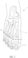
- a natural human foot 1 also includes metatarsal joints between the metatarsal bones 6 and the phalanges 8 that form the toes, as shown in Figure 2 . These joints allow the phalanges 8 to articulate relative to the metatarsal bones 6, such as at the natural metatarsal angles 14. This allows the posterior or heel of the foot to be angled relative to the forefoot or toes of the foot and allows the foot to further adapt to shoes having varying heel heights while providing support and balance.
- Some prosthetic feet currently available have a fixed ankle angle or are adapted primarily for use at a single heel height.
- Prosthetic feet according to the present disclosure advantageously allow for heel height adjustment and/or allow the toe to adapt to various heel heights to more closely mimic natural human feet (e.g., more closely approximate the functionality provided by the ankle and metatarsal joints of natural human feet).
- a prosthetic foot as described herein can generally include an adjustment and locking mechanism configured to lock the heel at a particular height (e.g., by locking an adapter of the foot at a particular angular orientation relative to a foot member of the foot) and/or a toe portion that allows the toe to adapt to various heel heights.
- a prosthetic foot includes an ankle module that allows for heel height adjustment and includes at least a portion of the locking mechanism.
- the ankle module can include an adapter or connector to couple the ankle module and therefore the prosthetic foot to a prosthetic pylon or socket.
- the adjustment and/or locking mechanism can advantageously allow the ankle and/or foot to be adjusted and locked so that the connector remains vertical or at least substantially vertical at different heel heights.
- the user can unlock the locking mechanism, adjust the foot (or allow the foot to adjust) to the correct height and alignment, then lock the locking mechanism.
- the prosthetic foot can be disposed in a cosmesis that can include a foot portion and/or a calf portion.
- FIG 3 illustrates one example embodiment of a prosthetic foot 1000 that allows for heel height adjustment.
- the prosthetic foot 1000 includes a lower foot member 1010, an intermediate foot member 1020, and an upper foot member 1030.
- the lower foot member 1010 is substantially plate-like and has a generally rectangular or rectangular cross-section transverse to a longitudinal axis of the lower foot member 1010 along at least a portion of its length.
- the lower foot member 1010 extends from a proximal or heel end 1012 to a distal or toe end 1014 and includes an arch region 1016 between the heel end 1012 and the toe end 1014, for example, at approximately the location of an arch of a natural human foot.
- the intermediate foot member 1020 is substantially plate-like and has a generally rectangular or rectangular cross-section transverse to the longitudinal axis along at least a portion of its length.
- the intermediate foot member 1020 extends from a proximal end 1022 downward and forward to a distal end 1024.
- the intermediate foot member 1020 is coupled to the lower member 1010 with one or more fasteners 1040, e.g., bolts, positioned proximate the distal end 1024 of the intermediate foot member 1020, and the lower foot member 1010 extends beyond or distal to the distal end 1024 of the intermediate foot member 1020.
- the distal end 1024 of the intermediate foot member 1020 and fasteners 1040 are positioned adjacent and distal to the arch region 1016 (e.g., proximate a portion of the foot 1000 generally corresponding to a metatarsal region of a natural human foot).
- the intermediate foot member 1020 tapers (e.g., gradually tapers) toward the proximal end 1022 such that the distal end 1024 of the intermediate foot member 1020 is thicker than the proximal end 1022.
- the upper foot member 1030 extends from a proximal end 1032 to a distal end 1034. As shown, the proximal end 1032 of the upper foot member 1030 can be coupled to the proximal end 1022 of the intermediate foot member 1020, for example, via one or more fasteners 1042 such as bolts. In the illustrated embodiment, there is a gap 1036 between the distal end 1034 of the upper foot member 1030 and a top surface of the intermediate foot member 1020.
- the gap 1036 can close and the upper foot member 1030 can engage the intermediate foot member 1020 to increase the stiffness of the foot 100 and/or store additional energy in the intermediate foot member 1020 as the foot 100 moves toward toe-off.
- the upper foot member 1030 is tapered (e.g., gradually tapered) toward the distal end 1034 such that the distal end 1034 is thinner than the proximal end 1032.
- the foot members or portions of the foot members can be constructed of a strong, resilient material that is capable of flexing in multiple directions, particularly during heel-strike through toe-off.
- the material can comprise multiple layers, or laminate. In some embodiments, the multiple layers or laminates when assembled form a monolithic member.
- Examples of possible materials for portion of the prosthetic foot include carbon, a polymer material, and a composite of polymer and fiber.
- the polymer can be thermoset or thermoplastic.
- the fiber reinforcement can be any type of fiber or filament, such as carbon, glass or aramid.
- the fibers can be long and unidirectional, or they can be chopped and randomly oriented.
- the intermediate foot member 1020 extends from the proximal end 1022 to a toe end
- the lower foot member 1010 is a heel plate that extends from a heel end to a distal end and includes an arch region between the heel end and the distal end.
- the heel plate is coupled to the intermediate foot member 1022 proximal to the toe end of the intermediate foot member 1020 and proximate to the distal end of the lower foot member 1010.
- the intermediate foot member 1022 tapers (e.g., gradually tapers) toward both the proximal end and distal toe end such that the intermediate foot member is thicker in a region where fasteners couple the intermediate foot member 1020 to the lower foot member 1010.
- the prosthetic foot 1000 does not include an upper foot member 1030.
- the prosthetic foot 1000 includes an ankle module 1100 placed adjacent and coupled to a top surface of the upper foot member 1030 at, adjacent, or proximate the proximal end 1032.
- the ankle module 1100 can also be coupled indirectly to the intermediate foot member 1020 because the proximal end 1022 of the intermediate foot member 1020 is coupled to the proximal end 1032 of the upper foot member 1030.
- the ankle module 1100 can be placed adjacent and coupled to the top surface of the intermediate foot member 1020 at, adjacent, or proximate the proximal end 1022.
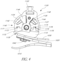
- the ankle module 1100 of the embodiment illustrated in Figure 3 includes a hydraulic adjustment and locking mechanism. As shown in Figures 3-4 , the ankle module 1100 includes a base portion 1110 and an adapter portion 1120.
- the base portion 1110 is coupled (e.g., fixedly coupled in the illustrated embodiment) to a foot member of the prosthetic foot 1000.
- the base portion 1110 is coupled to the upper foot member 1030 at, adjacent, or proximate the proximal end 1032.
- the base portion 1110 can be coupled to the intermediate foot member 1020 at, adjacent, or proximate the proximal end 1022.
- the base portion 1110 can be coupled to the upper foot member 1030 and/or intermediate foot member 1020 with one or more fasteners 1042 as shown.
- the adapter portion 1120 includes a connector or adapter 1122 that is coupled (e.g., fixedly coupled in the illustrated embodiment) to the user's residual limb via a socket or another prosthetic component, such as a pylon, in use.
- the adapter 1122 is a male pyramid.
- the adapter portion 1120 and base portion 1110 are pivotably or rotatably coupled via a pivot point or axle 1130 extending medially-laterally through the ankle module 1100.
- the adapter portion 1120 and base portion 1110 can be pivoted or rotated relative to each other in a dorsi-plantar direction to adjust an angle between the user's lower leg (e.g., the residual limb or pylon) and the prosthetic foot and therefore the heel height of the prosthetic foot.
- the axle 1130 can be fixedly coupled to the base portion 1110, and the adapter portion 1120 can be pivotably or rotatably coupled to the axle 1130.
- the axle 1130 can be fixedly coupled to the adapter portion 1120 and pivotably or rotatably coupled to the base portion 1110.
- the base portion 1110 includes projections or shoulders 1111 extending upward from medial and lateral sides of the base portion 1110 beyond a lower edge of the adapter portion 1120 (e.g., a lower edge of an outer housing 1124 of the adapter portion 1120, described below).
- the axle 1130 can extend through and be coupled (e.g. fixedly, pivotably, or rotatably) to the shoulders 1111.
- the adapter portion 1120 includes an outer housing 1124 and an intermediate wall 1126.
- the intermediate wall 1126 extends between an inner surface of the outer housing 1124 and a central hub 1127.
- the central hub 1127 encircles and can pivot or rotate about the axle 1130 that couples the adapter portion 1120 and base potion 1110.
- the intermediate wall 1126 is integrally formed with the outer housing 1124 and the central hub 1127.
- the intermediate wall 1126 can be separately formed from and coupled to the outer housing 1124 and/or the central hub 1127.
- the ankle module 1100 further includes an inner body 1140 including a proximal or rear piston 1142, a distal or front piston 1144, and a central cavity between the front 1144 and rear 1142 pistons.
- the intermediate wall 1126 divides the central cavity into rear and forward cylinders 1146, 1148.
- the cylinders 1146, 1148 house or contain hydraulic fluid.
- the outer housing 1124 and inner body 1140 have a generally semi-circular cross-section taken along a dorsi-plantar plane (as shown in Figure 4 ).
- the ankle module 1100 includes a spool valve 1150 extending medially-laterally through a bore in the adapter portion 1120.
- the bore and valve 1150 extend through the intermediate wall 1126, for example, an end of the intermediate wall 1126 proximate or adjacent the adapter 1122.
- a first hole 1152 extends through the intermediate wall 1126 from the rear cylinder 1146 to the bore and places the bore in fluid communication with the rear cylinder 1146.
- a second hole 1154 extends through the intermediate wall 1126 from the forward cylinder 1148 to the bore and places the bore in fluid communication with the forward cylinder 1148.
- the valve 1150 includes a reduced diameter portion 1153 having a length that allows the valve 1150 to be selectively positioned within the bore so that the first 1152 and second 1154 holes can fluidly communicate with each other via a gap between the reduced diameter portion 1153 and a surface of the bore.
- the valve 1150 includes three sealing members (e.g., o-rings), a first sealing member 1156a, a second sealing member 1156b, and a third sealing member 1156c.
- the sealing members 1156a, 1156b, 1156c seal against the surface of the bore to prevent or inhibit the fluid from flowing medially or laterally out of the valve 1150 and leaking from the ankle module 1100.
- the sealing members 1156a, 1156b, 1156c are all positioned medially or laterally of both the first 1152 and second 1154 holes. In other words, none of the sealing members 1156a, 1156b, 1156c is positioned between the first 1152 and second 1154 holes. Fluid can therefore flow between the rear cylinder 1146 and forward cylinder 1148 through the first 1152 and second 1154 holes and reduced diameter portion 1153 of the valve 1150.
- the second sealing member 1156b is positioned between the first hole 1152 and the second hole 1154. Fluid is therefore blocked, prevented, or inhibited from flowing between the cylinders 1146, 1148.
- the central hub 1127 rotates about the axle 1130 and the intermediate wall 1126 moves rearward toward the rear piston 1142. Rearward movement of the intermediate wall 1126 increases the angle between the user's lower limb and the foot, thereby increasing the heel height.
- the central hub 1127 rotates about the axle 1130 and the intermediate wall 1126 moves forward toward the front piston 1144, thereby decreasing the angle between the lower limb and the foot and decreasing the heel height.
- the front piston 1144 and rear piston 1142 can at least partially define a range of motion or adjustment for the ankle module 1100.
- the ankle module 1100 has a range of motion or adjustment of 7 cm or about 7 cm. In other words, the ankle module 1100 can adjust to heel heights over a range of 7 cm.
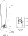
- the heel height can be defined as a distance between the ground or a support surface on which the user is standing in a neutral position and the heel end of the prosthetic foot (e.g., the proximal end 1012 of the lower foot member 1010) or the bottom surface of a heel portion of a cosmesis in which the prosthetic foot is received, for example as shown in Figure 18 , where HH indicates the heel height.
- the ankle module 1100 may allow adjustment of the heel height of the prosthetic foot from a flat foot position, e.g., 0 cm, to a heel height of 7 cm.
- a "flat foot" or neutral position of the prosthetic foot may have a heel height greater than 0 cm, e.g., 1 cm.
- the ankle module 1100 can allow adjustment of the heel height of the prosthetic foot from the flat foot position to a heel height of 7 cm greater than the flat foot heel height, for example, 8 cm in an embodiment in which the flat foot position has a heel height of 1 cm.
- the flat foot or neutral position may have a heel height greater than 0 cm
- the ankle module 1100 can allow adjustment of the heel height between 0 cm and, for example, 7 cm.
- the ankle module 1100 can have a range of motion or adjustment of greater than or less than 7 cm.
- the ankle module 1120 can include a front bumper 1170 and a rear bumper 1172.
- the front bumper 1170 is positioned proximate or adjacent the front piston 1144 (an end of the front piston 1144 opposite an end of the front piston 1144 that is adjacent the forward cylinder 1148).
- the front piston 1144 may contact the front bumper 1170 in use.
- the rear bumper 1172 is positioned proximate or adjacent the rear piston 1142 (an end of the rear piston 1142 opposite an end of the rear piston 1142 that is adjacent the rear cylinder 1146).
- the rear piston 1142 may contact the rear bumper 1172 in use.
- the front 1170 and rear 1172 bumpers can help minimize or reduce play in the ankle module 1100.
- the front 1170 and rear 1172 bumpers can act as accumulators and store energy during use.
- a stiff member 1174 is positioned between at least a portion of the front bumper 1170 and the front piston 1144.
- the rear piston 1142 includes a recess 1171 to receive a corresponding protrusion 1173 of the rear bumper 1172.
- the front piston 1144 includes a recess 1175 to receive a corresponding protrusion 1176 of the front bumper 1170.
- one or both of the pistons 1144, 1142 can be compressed to remove air from the hydraulic chambers.
- the angle of the lower surfaces of the pistons 1144, 1142 i.e., the end surfaces of the pistons 1144, 1142 positioned toward or facing the base portion 1110 may change.
- the bumpers 1172, 1170 can deform to accommodate such changes or tolerances.
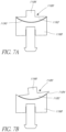
- the ankle module 1120 can include one or more at least partially spherical washers 1180 as shown in Figures 6-7B .
- a washer 1180 can be coupled, e.g., fixedly coupled, to or relative to the lower surface of one or both of the pistons 1142, 1144.
- a washer 1180 is coupled to the front piston 1144.
- the washer 1180 has a partial spherical portion 1182 having a downward-facing convex partially spherical bottom surface 1184 and a post 1186 extending upward from the partial spherical portion.
- the post 1186 is coupled to the piston 1144, 1142.
- a piston base 1188 is coupled, e.g., fixedly coupled, to the base portion 1110.
- the piston base 1188 has an upward-facing concave upper surface 1190 that receives and/or accommodates the downward-facing convex bottom surface 1184 of the washer 1180 as shown.
- the washer 1180 can pivot or rotate relative to the piston base 1188 to accommodate and adapt to changes in the angle between the piston 1144, 1142 and the base portion 1110.
- the ankle module 1100 includes a ball lock system 1160 that allows the spool valve 1150 to be adjusted to and/or locked in the open and/or closed position.
- the ball lock system 1160 is actuatable to slide within a channel in the ankle module 1100 to operate the spool valve 1150 between the open and locked positions.
- the ball lock system 1160 includes an end portion or button 1162, a plurality of balls 1164, and at least one spring 1166.
- the adapter portion 1120 and/or inner body 1140 includes recesses that receive the balls 1164.
- a cap piece 1125 is coupled to and/or within a projection 1123 extending medially or laterally from the outer housing 1124.
- the adapter portion 1120, inner body 1140, and/or projection 1123 includes a first set of recesses 1168 positioned relatively more centrally that receive the balls 1164 when the valve 1150 is in the closed position.
- the adapter portion 1120, inner body 1140, and/or projection 1123 includes a second set of recesses 1169 positioned relatively more medially or laterally that receive the balls 1164 when the valve 1150 is in the open position.
- the user presses the button 1162 to move the balls 1164 and the valve 1150 between the open and closed positions.
- the spring(s) 1166 spring loads the balls 1164, which advantageously provides the user with tactile feedback that the valve 1150 has been fully moved to the desired open or closed position.
- Such tactile feedback can be particularly useful when the prosthetic foot 1000 is disposed within a cosmesis, for example as described in greater detail herein, and the user is therefore depressing the button 1162 through the cosmesis.
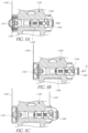
- Figures 8A-8B illustrate an alternative system and method for opening and closing the spool valve 1150.
- the ankle module includes a ball lock system 1160 that extends through a channel in the ankle module.
- the ball lock system 1160 is actuatable to slide within the channel to operate the spool valve 1150 between the open and closed positions.
- the ball lock system 1160 includes a first end portion, e.g., a button, 1162, a plurality of balls 1164 and at least one spring 1166 similar to the embodiment of Figure 5 , as well as a second end portion 1161, at least one button spring 1163 positioned between the second end portion 1161 and the outer housing 1124, and a wire 1165.
- the wire 1165 is attached to and/or extends through the second end portion 1161.
- the wire 1165 can have a distal end secured (e.g., anchored) in a side wall defined by the ankle module housing, where the sidewall at least partially defines an opening through which the second end portion 1161 moves.
- the wire 1165 can then extend through (e.g., through an opening in) an opposite side wall that at least partially defines the opening through which the second end portion 1161 moves, as shown in in FIGS, 8A-8B .
- the user can pull on the wire 1165, thereby causing the wire 1165 to press the second end portion 1161 in and shift the spool valve 1150 to the open position as shown in Figure 8B . Movement of the second end portion 1161 in toward the housing 1124 compresses the button spring(s) 1163 as shown. The user can then adjust the ankle module 1100 as desired or required.
- the user can push the first end portion 1162 in, as indicated by arrow C in Figure 8B .
- the ball lock system 1160 can include a secondary wire 1167 attached to and/or extending through the first end portion 1162, as shown in Figure 8C .
- the secondary wire 1167 can have a distal end secured (e.g., anchored) in a side wall defined by the ankle module housing, where the sidewall at least partially defines an opening through which the first end portion 1162 moves.
- the secondary wire 1167 can then extend through (e.g., through an opening in) an opposite side wall that at least partially defines the opening through which the first end portion 1162 moves, as shown in in FIGS, 8C .
- the user can pull the secondary wire 1167, thereby causing the secondary wire 1167 to press the first end portion 1162 in toward the housing 1124 and shift the spool valve 1150 back to its initial or closed position.
- the wire(s) 1165, 1167 can be attached to the ankle module 1100, another prosthetic component, and/or a socket attached to the user's residual limb, e.g., via magnets, for storage.
- Prosthetic feet according to the present disclosure advantageously allow for heel height adjustability as described herein.
- modifying the heel height alone without adjusting other sections of the prosthetic foot e.g., the toe region
- prosthetic feet according to the present disclosure advantageously include features that provide metatarsal joint functionality or allow the toe portion to adapt to various heel heights to more closely mimic natural human feet.
- the prosthetic foot 1000 of Figure 3 can include a toe portion 1018 that allows the foot 1000 to accommodate heel height adjustments made at the ankle module 1100.
- the toe portion 1018 curves upward relative to a portion of the foot member, e.g., foot member 1010, proximal to the toe portion 1018.
- the toe portion 1018 is curved more upward compared to a foot member 22' having a toe portion that is flat or has a slight curvature designed for flat or relatively flat shoes.
- the user's weight shifts to be supported by different areas of the toe portion 1018 as the heel height is adjusted.
- the user's weight rests at or proximate a proximal end of the toe portion 1018.
- the toe portion 1018 therefore allows the lower foot member 1010 and/or prosthetic foot 1000 to automatically adapt to varying heel heights without the need for separate adjustment.
- the curvature of the toe portion 1018 can advantageously allow the foot 1000 to achieve a better fit in various shoes, including high heeled shoes.
- the curvature of the toe portion 1018 can also or alternatively help reduce wear on the foot 1000, e.g., the foot member 1010, during use.
- the curvature of the toe portion 1018 can be selected to allow the toe portion 1018 to adapt to varying heel heights while providing sufficient push off during the toe off portion of the gait cycle.
- the toe portion 1018 includes a generally U-shaped cut-out portion, slot, or gap 1017 extending inwardly or proximally from a distal toe end, for example as shown in Figures 11-14 .
- the cut-out 1017 is positioned toward a medial side of a longitudinal axis of the lower foot member 1010, but is spaced from a medial edge of the lower foot member 1010.
- the cut-out 1017 gives the lower foot member 1010 a "sandal toe" appearance and/or function and defines a structural "big toe” 1019.
- the cut out portion 1017 can receive a strap of a sandal.
- the big toe 1019 is longer (e.g., extends further distally) than the remaining "toes" or the remainder of the toe portion 1018.
- the lower foot member 1010 can also include a split 1015 that at least partially extends substantially along the longitudinal axis of the lower foot member 1010 to the cut-out 1017. As shown in Figure 11 , the transition between the split 1015 and the cut-out 1017 can be rounded, or can lack sharp corners. This can advantageously reduce delamination of the toe portion 1018 during manufacturing and/or failure of the toe portion 1018 in use.
- the prosthetic foot 1000 includes a toe piece 1092 coupled to a top surface of at least a portion of the toe portion 1018, as shown in Figures 12-14 .
- the toe piece 1092 is sized, shaped, and/or otherwise designed to follow the outer contours of the toe portion 1018.
- the toe piece 1092 can be made of a resilient material, e.g., rubber.
- the toe piece 1092 includes a big toe portion 1094 that overlies and/or is coupled to the big toe 1019 of the lower foot member 1010 and a body portion 1096 that overlies and/or is coupled to the remainder of the toe portion 1018.
- the big toe portion 1094 can be coupled to the body portion 1096 by a bridge piece 1095 as shown.
- the toe piece 1092 has a thickness or height (e.g., tapering toward the front end such that the front end is thinner than a rear end of the toe piece 1092) selected to fill or at least partially fill space between the toe portion 1018 of the lower foot member 1010 and an inner surface of a cosmesis, for example as described herein, if and when the prosthetic foot 1000 is disposed in the cosmesis for use.
- the toe piece 1092 can therefore reduce relative motion between the toe portion 1018 and cosmesis in use (e.g., by exerting a friction force between a surface of the toe piece 1092 and an inner upper surface of the cosmesis), which can advantageously reduce wear on the cosmesis.
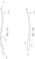
- Figures 15A-15B illustrate another example embodiment of a foot member 1010' having a toe portion 1018' that adapts to varying heel heights.
- the toe portion 1018' includes glass fiber.
- the glass fiber can advantageously increase the flexibility of the toe portion 1018'.
- the toe portion 1018' is curved upward similar to the toe portion 1018 shown in Figures 9-10 .
- the toe portion 1018' is flat or has a curvature similar to the foot member 22' shown in Figures 9-10 or other available foot members designed for flat or relatively flat shoes.
- the foot member 1010' is made of a layup including one or more layers of glass fiber or a glass composite that extend from the proximal end 1012' to the distal end 1014' and one or more layers of carbon or a carbon composite that extend from the proximal end 1012' to a point proximal and adjacent or proximate to a proximal end of the toe portion 1018'.
- the foot member 1010' can include upper and lower portions 1011 that include one or more layers of glass fiber that extend the full length of the foot member 1010' and a central portion 1013 of carbon fiber that extends to a point proximal to the toe portion 1018'.
- the layers of glass fiber may not extend to the proximal end 1012'.
- a prosthetic foot that allows for heel height adjustability as described herein can be disposed in a cosmesis configured to resemble a natural human foot.
- a conventional cosmesis may not allow for heel height adjustability or may wrinkle when the heel height is adjusted, which may impede the foot from fully adjusting to the desired heel height and/or may make the cosmesis less aesthetically pleasing.
- Figures 16-17 illustrate an example embodiment of a cosmesis 1200 that includes a foot portion 1210 and a calf portion 1220 (also shown in Figures 21A-21B ).
- the foot 1210 and calf 1220 portions can be used together, as shown in Figures 16-17 , or either portion can be used alone or separately.
- a prosthetist glues or otherwise couples the foot 1210 and calf 1220 portions together for example, as is done with some conventional cosmeses.
- the connection instead of the connection between the calf portion 1220 and foot portion 1210 being at or between the top edge or surface of the foot portion 1210 and the bottom edge or surface of the calf portion 1220, the connection can be located along an inner surface of the foot portion 1210.
- the foot portion 1210 can include a recess 1212 defined on or in an inner surface 1213 proximate the upper edge or surface of the foot portion 1210.
- the recess 1212 is sized, shaped, and/or otherwise designed to receive a lower lip 1222 of the calf portion 1220.
- the calf portion 1220 can include a recess 1224 proximate the lower edge or surface of the calf portion 1220 to receive an upper lip 1214 of the foot portion 1210 as shown. Accordingly, the calf cosmesis can be coupled with the foot cosmesis so that no portion of the connection is visible while in use, and so the combined calf and foot cosmesis assembly appears seamless.
- the junction between the calf portion 1220 and foot portion 1210 of the cosmesis 1200 is lower than in some conventional covers.
- the junction or seam is covered by the shoe when the cosmesis is disposed in a shoe.
- the junction or seam is at least partially positioned or curves below the location of the malleoli on a natural human foot and/or below the location of the ankle module.
- the junction or seam may be relatively stiff compared to other areas of the cosmesis 1200.
- Positioning the junction below the location of the ankle module can advantageously allow the portion of the cosmesis 1200 around the ankle module to be relatively more flexible than the junction to allow the cosmesis 1200 to stretch and/or otherwise accommodate rotation or other movement at the ankle.
- the cosmesis is made of EVA.
- Figures 16-17 illustrate the cosmesis 1200 in combination with the prosthetic foot 1000. However, either of both of the foot portion 1210 and calf portion 1220 can be adapted for use with other prosthetic feet designs.
- a wall of the calf portion 1220 is thinner in the region(s) designed to be adjacent or surrounding the first end portion or button 1162 and/or second end portion 1161 when the prosthetic foot is disposed in the cosmesis 1200 (or another cosmesis including calf portion 1220).
- the thinner region can allow the user to more easily press or access the first end portion 1162 and/or second end portion 1161 through the calf portion 1220 to adjust the heel height of the prosthetic foot 1000.
- portions of the wall of the calf portion 1220 designed to be adjacent or proximate the front and/or rear of the ankle module 1100 when the prosthetic foot is disposed in the cosmesis 1200 (or another cosmesis including calf portion 1220) are thicker than a remainder of the calf portion 1220. These thickened portions can help inhibit or reduce the likelihood of wrinkling of the calf portion 1220 during use and/or as the ankle module 1100 is adjusted.
- the calf portion 1220 can be provided to a prosthetist such that an outer surface of the calf portion 1220 is ready for use, and the prosthetist can grind an inner surface of the calf portion 1220 as needed, for example, to thin the region(s) adjacent or surrounding the first end portion 1162 and/or second end portion 1161 and/or to make space at or proximate an upper end of the calf portion 1220 to accommodate a socket coupled to the user's residual limb.
- the foot portion 1210 can have an intermediate heel height, for example, approximately 1 cm - 5 cm, approximately 2 cm - 4 cm, or approximately 3 cm, built into the cosmesis so that the cosmesis has an intermediate heel height in a neutral position.
- the cosmesis can then adjust to a range of heel heights from a flat foot or minimal heel height position, e.g., 0 cm, up to a height of, for example, around 7 cm with little deformation.
- Figure 19 illustrates another example embodiment of a foot cosmesis 1230 or foot portion of a cosmesis.
- the cosmesis 1230 is design for use with the prosthetic foot 1000 shown in and described with respect to Figure 3 .
- the cosmesis 1230 can be adapted for use with other prosthetic foot designs or configurations.
- the prosthetic foot e.g., prosthetic foot 1000
- a neutral heel height e.g., a minimum heel height or an intermediate heel height in an embodiment in which an intermediate heel height is built into the cosmesis
- the gap 1232 advantageously allows the cosmesis 1230 to deform to adapt to shoes having various heel heights, for example, with reduced, minimal, or no wrinkling.
- the heel height is increased the foot member flexes toward the inner surface of the sole portion of the cosmesis 1230, decreasing and eventually closing the gap 1232.
- the arch region of the inner surface of the sole portion of the cosmesis 1230 can include a region 1234 of channels or recesses formed in the inner surface.
- the channels or recesses can be arranged in a honeycomb pattern, for example as shown in Figure 20 .
- the region 1234 of channels or recesses can allow the sole portion to flex to adapt to shoes having various heel heights.
- various feet and/or ankle modules shown and described herein can be configured to be compatible with vacuum suspension systems.
- Such a system generates negative pressure within a prosthetic socket to improve the fit and stability of the socket relative to the residual limb.
- the distal end of the residual limb typically has more soft tissue compared to the area closer to the knee. The distal end is therefore more susceptible to volume fluctuations throughout the day, which can impede stabilization and suspension of the socket.
- a vacuum suspension system that can be used with the feet described herein can therefore apply a vacuum to the distal end of the residual limb to improve stability and suspension.
- the system can include a frame coupled to the foot and a membrane disposed on or between parts of the frame.
- each embodiment of this invention may comprise, additional to its essential features described herein, one or more features as described herein from each other embodiment of the invention disclosed herein.
- the terms “generally parallel” and “substantially parallel” refer to a value, amount, or characteristic that departs from exactly parallel by less than or equal to 15 degrees, 10 degrees, 5 degrees, 3 degrees, 1 degree, 0.1 degree, or otherwise.
Description
- The present application relates to foot prostheses in general, and more particularly, to prosthetic feet and ankles configured to allow for heel height adjustability.
- Various types of prosthetic foot and ankle devices are available as substitutes for human feet. Some prosthetic foot devices allow for heel height adjustment, for example, so that the user can wear shoes having different heel heights. However, in some cases, modifying the heel height alone without adjusting other sections of the prosthetic foot (e.g., the toe region) can place the foot in an unnatural position, which can result in discomfort for the user or a sub-optimal rollover performance during use. Additionally, some prosthetic foot devices allow for heel height adjustment at the ankle, but do not provide a mechanism for locking the ankle at a particular heel height. This can have an adverse effect on stability and/or performance of the foot in use.
-
US 2005/0137717 A1 discloses a prosthetic foot that comprises a foot member, a rocker member connected in cantilever fashion to the foot member, and an ankle module movably connected to the rocker member about an axis, wherein an anterior section of the rocker member is configured to roll-up onto the foot member an amount corresponding to the load applied on the foot, and wherein the foot member is configured to facilitate the initial roll-up of the rocker member. - The present invention is defined by the appended claims only, in particular by the scope of appended
independent claim 1. Reference(s) to "embodiments" throughout the description which are not under the scope of the appended claims merely represents possible exemplary executions and are therefore not part of the present invention. - In some embodiments a prosthetic foot includes an ankle module, an elongate foot member, and an elongate lower foot member. The ankle module is configured to be coupled to a lower limb member. The elongate foot member extends from a proximal end to a distal end, and the proximal end is coupled to the ankle module. The elongate lower foot member extends from a proximal end to a distal end, is positioned below and coupled to the foot member, and extends distally beyond the distal end of the foot member to form a toe region. The ankle module is selectively actuatable to adjust an angle between the prosthetic foot and the lower limb member to allow for adjustment of a heel height of the prosthetic foot. The toe region curves upward and is configured to adapt to various heel heights of the prosthetic foot.
- In some embodiments, the ankle module comprises a hydraulic adjustment mechanism. In some embodiments, the toe region comprises glass fiber. In some embodiments, the lower foot member comprises one or more layers of glass fiber extending from the proximal end to the distal end and one or more layers of carbon fiber extending from the proximal end to a point proximal of the distal end. The prosthetic foot can further include an upper foot member extending from a proximal end to a distal end, the upper foot member positioned above the foot member and the proximal end coupled to the proximal end of the foot member and the ankle module. The distal end of the upper foot member can be separated from the foot member by a gap when the prosthetic foot is at rest in a neutral position. The toe region can include a generally U-shaped cut-out extending proximally from the distal end of the lower foot member, the lower foot member can include a split extending at least partially along a longitudinal axis of the lower foot member to the cut-out, and a transition between the split and the cut-out can be rounded. The prosthetic foot can include a toe piece coupled to a top surface of the toe region. The toe piece can taper toward a front or distal end of the toe piece.
- In some embodiments, a prosthetic foot includes an elongate foot member, an elongate lower foot member, and an ankle module. The elongate foot member extends from a proximal end to a distal end. The elongate lower foot member extends from a proximal end to a distal end, is positioned below and coupled to the foot member, and extends distally beyond the distal end of the foot member to form a toe region. The ankle module is coupled to the proximal end of the foot member and configured to be coupled to a lower limb member. The ankle module includes first and second pistons, a central cavity between the first and second pistons, a hydraulic fluid in the central cavity, an intermediate wall separating the central cavity into first and second cylinders, a spool valve extending through the intermediate wall, the spool valve actuatable to selectively place the first and second cylinders in fluid communication, and a ball lock actuatable to selectively place the valve in an open or closed position, the ball lock comprising a first end portion or button, one or more balls, and at least one spring. The ankle module is selectively actuatable to adjust an angle between the prosthetic foot and the lower limb member to allow for adjustment of a heel height of the prosthetic foot. The ball lock can include a second end portion disposed opposite the first end portion along the spool valve, at least one button spring, and a wire attached to the second end portion. When a user pulls the wire in use, the wire can cause movement of the second end portion, thereby shifting the spool valve to the open position and compressing the at least one button spring. The ball lock can include a secondary wire attached to the first end portion. When a user pulls the secondary wire in use, the secondary wire can cause movement of the first end portion, thereby shifting the spool valve to the closed position. The ankle module can include a washer coupled to a lower surface of at least one of the first and second pistons and a piston base coupled to a base portion of the ankle module. The washer can have a downward-facing convex bottom surface, and the piston base can have an upward-facing concave upper surface configured to pivotably receive the downward-facing convex bottom surface of the washer to accommodate changes in an angle between the at least one of the first and second pistons and the base portion.
- In some embodiments, the toe region curves upward and is configured to adapt to various heel heights of the prosthetic foot. In some embodiments, the toe region comprises glass fiber. In some embodiments, the lower foot member comprises one or more layers of glass fiber extending from the proximal end to the distal end and one or more layers of carbon fiber extending from the proximal end to a point proximal of the distal end. The prosthetic foot can further include an upper foot member extending from a proximal end to a distal end, the upper foot member positioned above the foot member and the proximal end coupled to the proximal end of the foot member and the ankle module. The distal end of the upper foot member can be separated from the foot member by a gap when the prosthetic foot is at rest in a neutral position.
- In some embodiments, a prosthetic foot includes an elongate foot member, an ankle module, and a cosmesis. The elongate foot extends from a proximal end to a distal end and has an arch region therebetween. The ankle module is operably coupled to the foot member and configured to be coupled to a lower limb member. The ankle module is selectively actuatable to adjust an angle between the prosthetic foot and the lower limb member to allow for adjustment of a heel height of the prosthetic foot. The cosmesis is configured to receive the foot member. When the foot member is disposed in the cosmesis and the foot is resting on a support surface in a neutral position with the prosthetic foot adjusted to a neutral heel height, the arch region of the foot member is separated from an inner surface of a sole portion of the cosmesis by a gap. The gap can allow the cosmesis to adapt to varying heel heights of the prosthetic foot.
- In some embodiments, the foot member includes a toe region adjacent the distal end. The toe region can curve upward and be configured to adapt to various heel heights of the prosthetic foot. The toe region can include a glass fiber. In some embodiments, the foot member comprises one or more layers of glass fiber extending from the proximal end to the distal end and one or more layers of carbon fiber extending from the proximal end to a point proximal of the distal end. A toe piece can be coupled to a top surface of the toe region to at least partially fill a gap between the toe region and an inner surface of the cosmesis.
- In some embodiments, a cosmesis for a prosthetic foot member includes an outer wall defining an inner cavity, the inner cavity is configured to receive the prosthetic foot, and a heel end of the outer wall is vertically offset from a toe end of the outer wall by a distance in the range of about 2 cm to about 4 cm.
- In some embodiments, a cosmesis for a prosthetic foot includes a foot portion and a calf portion. The foot portion includes an opening at a top end extending into a cavity formed within the foot portion, the cavity configured to removably receive the prosthetic foot therein, and a wall surrounding the cavity. A lower end of the calf portion can be configured to be coupled to the top end of the foot portion about the opening, and the foot portion can have a height such that the top end and opening are configured to be positioned below an opening of a shoe when the cosmesis is disposed in the shoe. In some embodiments, the foot portion includes a recess in an inner surface of the foot portion proximate the top end, and the calf portion includes a lip adjacent the lower end, and the recess is configured to receive the lip.
- In some embodiments, a cosmesis for a prosthetic foot including an ankle module includes a foot portion and a calf portion. The foot portion includes an opening at a top end extending into a cavity formed within the foot portion, the cavity configured to removably receive the prosthetic foot therein, and a wall surrounding the cavity. The calf portion includes a wall surrounding a cavity, a lower end of the calf portion is configured to be coupled to the top end of the foot portion about the opening, and a portion of the wall of the calf portion configured to be positioned proximate an adjustment button of the ankle module when the prosthetic foot is disposed in the cosmesis has a thickness less than a thickness of a remainder of the wall of the calf portion. In some embodiments, the foot portion has a height such that the top end and opening are configured to be positioned below an opening of a shoe when the cosmesis is disposed in the shoe.
- All of these embodiments are intended to be within the scope of the disclosure herein. These and other embodiments will become readily apparent to those skilled in the art from the following detailed description having reference to the attached figures, the disclosure not being limited to any particular disclosed embodiment(s).
- These and other features, aspects, and advantages of the present disclosure are described with reference to the drawings of certain embodiments, which are intended to schematically illustrate certain embodiments and not to limit the disclosure.
-
Figure 1 illustrates a schematic of a natural human ankle joint; -
Figure 2 illustrates a schematic of bones and joints of a natural human foot; -
Figure 3 illustrates an example embodiment of a prosthetic foot having heel height adjustability. -
Figure 4 illustrates a longitudinal cross-sectional view of an ankle module of the prosthetic foot ofFigure 3 . -
Figure 5 illustrates a top sectional view of the ankle module ofFigure 4 . -
Figure 6 illustrates a perspective longitudinal cross-sectional view of an example embodiment of an ankle module. -
Figures 7A-7B illustrate schematics of a spherical washer of the ankle module ofFigure 6 . -
Figures 8A-8C illustrate schematic side cross-sectional views an example embodiment of an ankle module showing operation of a flow valve. -
Figure 9 illustrates a foot member of the prosthetic foot ofFigure 3 that is configured to adapt to varying heel heights compared to a foot member designed for a standard, flat, or neutral heel height. -
Figure 10 illustrates the prosthetic foot ofFigure 3 compared to the foot member designed for a standard, flat, or neutral heel height. -
Figure 11 illustrates a top close-up view of a toe portion of a prosthetic foot. -
Figure 12 illustrates a side view of an example embodiment of a prosthetic foot having heel height adjustability. -
Figure 13 illustrates a rear-side perspective view of the prosthetic foot ofFigure 12 . -
Figure 14 illustrates a top view of the prosthetic foot ofFigure 12 . -
Figure 15A illustrates an example embodiment of a foot member having a toe portion configured to adapt to varying heel heights. -
Figure 15B illustrates a close-up view of a toe portion of the foot member ofFigure 15A . -
Figure 16 illustrates the prosthetic foot ofFigure 3 disposed in an example embodiment of a cosmesis including a foot portion and calf portion. -
Figure 17 illustrates a partial front sectional view of the prosthetic foot and cosmesis ofFigure 16 . -
Figure 18 illustrates the prosthetic foot and foot portion of the cosmesis ofFigure 8 . -
Figure 19 illustrates a longitudinal cross-sectional view of an example embodiment of a foot cosmesis. -
Figure 20 illustrates a partial top-side perspective longitudinal cross-sectional view of an example embodiment of a foot cosmesis. -
Figure 21A illustrates a front view of the calf portion of the cosmesis ofFigure 8 . -
Figure 21B illustrates a rear view of the calf portion of the cosmesis ofFigure 8 . -
Figure 22 illustrates a schematic longitudinal cross-sectional view of a connection between a calf cosmesis and a foot cosmesis. - Although certain embodiments and examples are described below, those of skill in the art will appreciate that the disclosure extends beyond the specifically disclosed embodiments and/or uses and obvious modifications and equivalents thereof. Thus, it is intended that the scope of the disclosure herein disclosed should not be limited by any particular embodiments described below.
- A natural human ankle allows for changes in an angle between the lower leg and the foot. This allows the foot and ankle to, among other things, adapt to shoes having different heel heights. For example, a natural human ankle can allow for angular adjustment about a pivot point at the ankle joint 40, as shown in
Figure 1 . A naturalhuman foot 1 also includes metatarsal joints between themetatarsal bones 6 and thephalanges 8 that form the toes, as shown inFigure 2 . These joints allow thephalanges 8 to articulate relative to themetatarsal bones 6, such as at the natural metatarsal angles 14. This allows the posterior or heel of the foot to be angled relative to the forefoot or toes of the foot and allows the foot to further adapt to shoes having varying heel heights while providing support and balance. - Some prosthetic feet currently available have a fixed ankle angle or are adapted primarily for use at a single heel height. Prosthetic feet according to the present disclosure advantageously allow for heel height adjustment and/or allow the toe to adapt to various heel heights to more closely mimic natural human feet (e.g., more closely approximate the functionality provided by the ankle and metatarsal joints of natural human feet).
- A prosthetic foot as described herein can generally include an adjustment and locking mechanism configured to lock the heel at a particular height (e.g., by locking an adapter of the foot at a particular angular orientation relative to a foot member of the foot) and/or a toe portion that allows the toe to adapt to various heel heights. In some embodiments, a prosthetic foot includes an ankle module that allows for heel height adjustment and includes at least a portion of the locking mechanism. The ankle module can include an adapter or connector to couple the ankle module and therefore the prosthetic foot to a prosthetic pylon or socket. The adjustment and/or locking mechanism can advantageously allow the ankle and/or foot to be adjusted and locked so that the connector remains vertical or at least substantially vertical at different heel heights. When changing to a shoe having a different heel height, the user can unlock the locking mechanism, adjust the foot (or allow the foot to adjust) to the correct height and alignment, then lock the locking mechanism. In some embodiments, the prosthetic foot can be disposed in a cosmesis that can include a foot portion and/or a calf portion.
-
Figure 3 illustrates one example embodiment of aprosthetic foot 1000 that allows for heel height adjustment. In the illustrated embodiment, theprosthetic foot 1000 includes alower foot member 1010, anintermediate foot member 1020, and anupper foot member 1030. Thelower foot member 1010 is substantially plate-like and has a generally rectangular or rectangular cross-section transverse to a longitudinal axis of thelower foot member 1010 along at least a portion of its length. Thelower foot member 1010 extends from a proximal orheel end 1012 to a distal ortoe end 1014 and includes anarch region 1016 between theheel end 1012 and thetoe end 1014, for example, at approximately the location of an arch of a natural human foot. - The
intermediate foot member 1020 is substantially plate-like and has a generally rectangular or rectangular cross-section transverse to the longitudinal axis along at least a portion of its length. Theintermediate foot member 1020 extends from aproximal end 1022 downward and forward to adistal end 1024. As shown, theintermediate foot member 1020 is coupled to thelower member 1010 with one ormore fasteners 1040, e.g., bolts, positioned proximate thedistal end 1024 of theintermediate foot member 1020, and thelower foot member 1010 extends beyond or distal to thedistal end 1024 of theintermediate foot member 1020. In the illustrated embodiment, thedistal end 1024 of theintermediate foot member 1020 andfasteners 1040 are positioned adjacent and distal to the arch region 1016 (e.g., proximate a portion of thefoot 1000 generally corresponding to a metatarsal region of a natural human foot). In some embodiments, theintermediate foot member 1020 tapers (e.g., gradually tapers) toward theproximal end 1022 such that thedistal end 1024 of theintermediate foot member 1020 is thicker than theproximal end 1022. - The
upper foot member 1030 extends from aproximal end 1032 to adistal end 1034. As shown, theproximal end 1032 of theupper foot member 1030 can be coupled to theproximal end 1022 of theintermediate foot member 1020, for example, via one ormore fasteners 1042 such as bolts. In the illustrated embodiment, there is agap 1036 between thedistal end 1034 of theupper foot member 1030 and a top surface of theintermediate foot member 1020. During the mid-stance and toe-off phases of the gait cycle, thegap 1036 can close and theupper foot member 1030 can engage theintermediate foot member 1020 to increase the stiffness of the foot 100 and/or store additional energy in theintermediate foot member 1020 as the foot 100 moves toward toe-off. In some embodiments, theupper foot member 1030 is tapered (e.g., gradually tapered) toward thedistal end 1034 such that thedistal end 1034 is thinner than theproximal end 1032. - In some embodiments, the foot members or portions of the foot members can be constructed of a strong, resilient material that is capable of flexing in multiple directions, particularly during heel-strike through toe-off. The material can comprise multiple layers, or laminate. In some embodiments, the multiple layers or laminates when assembled form a monolithic member. Examples of possible materials for portion of the prosthetic foot include carbon, a polymer material, and a composite of polymer and fiber. The polymer can be thermoset or thermoplastic. In a composite, the fiber reinforcement can be any type of fiber or filament, such as carbon, glass or aramid. The fibers can be long and unidirectional, or they can be chopped and randomly oriented. Other filaments, such as Kevlar and nylon, can also be used to ensure lightweight and structurally dynamic characteristics. Additional details regarding the lower 1010, intermediate 1020, and/or upper 1030 foot members can be found in
U.S. Publication No. 2016/0310298 . - Other arrangements of foot members are also possible. For example, in some embodiments, the
intermediate foot member 1020 extends from theproximal end 1022 to a toe end, and thelower foot member 1010 is a heel plate that extends from a heel end to a distal end and includes an arch region between the heel end and the distal end. The heel plate is coupled to theintermediate foot member 1022 proximal to the toe end of theintermediate foot member 1020 and proximate to the distal end of thelower foot member 1010. In some such embodiments, theintermediate foot member 1022 tapers (e.g., gradually tapers) toward both the proximal end and distal toe end such that the intermediate foot member is thicker in a region where fasteners couple theintermediate foot member 1020 to thelower foot member 1010. In some embodiments, theprosthetic foot 1000 does not include anupper foot member 1030. - In the illustrated embodiment, the
prosthetic foot 1000 includes anankle module 1100 placed adjacent and coupled to a top surface of theupper foot member 1030 at, adjacent, or proximate theproximal end 1032. As shown, theankle module 1100 can also be coupled indirectly to theintermediate foot member 1020 because theproximal end 1022 of theintermediate foot member 1020 is coupled to theproximal end 1032 of theupper foot member 1030. In embodiments not including anupper foot member 1030, theankle module 1100 can be placed adjacent and coupled to the top surface of theintermediate foot member 1020 at, adjacent, or proximate theproximal end 1022. - The
ankle module 1100 of the embodiment illustrated inFigure 3 includes a hydraulic adjustment and locking mechanism. As shown inFigures 3-4 , theankle module 1100 includes abase portion 1110 and anadapter portion 1120. Thebase portion 1110 is coupled (e.g., fixedly coupled in the illustrated embodiment) to a foot member of theprosthetic foot 1000. In the illustrated embodiment, thebase portion 1110 is coupled to theupper foot member 1030 at, adjacent, or proximate theproximal end 1032. In embodiments not including theupper foot member 1030, thebase portion 1110 can be coupled to theintermediate foot member 1020 at, adjacent, or proximate theproximal end 1022. Thebase portion 1110 can be coupled to theupper foot member 1030 and/orintermediate foot member 1020 with one ormore fasteners 1042 as shown. Theadapter portion 1120 includes a connector oradapter 1122 that is coupled (e.g., fixedly coupled in the illustrated embodiment) to the user's residual limb via a socket or another prosthetic component, such as a pylon, in use. In the illustrated embodiment, theadapter 1122 is a male pyramid. - The
adapter portion 1120 andbase portion 1110 are pivotably or rotatably coupled via a pivot point oraxle 1130 extending medially-laterally through theankle module 1100. Theadapter portion 1120 andbase portion 1110 can be pivoted or rotated relative to each other in a dorsi-plantar direction to adjust an angle between the user's lower leg (e.g., the residual limb or pylon) and the prosthetic foot and therefore the heel height of the prosthetic foot. Theaxle 1130 can be fixedly coupled to thebase portion 1110, and theadapter portion 1120 can be pivotably or rotatably coupled to theaxle 1130. In other embodiments, theaxle 1130 can be fixedly coupled to theadapter portion 1120 and pivotably or rotatably coupled to thebase portion 1110. In the illustrated embodiment, thebase portion 1110 includes projections orshoulders 1111 extending upward from medial and lateral sides of thebase portion 1110 beyond a lower edge of the adapter portion 1120 (e.g., a lower edge of anouter housing 1124 of theadapter portion 1120, described below). Theaxle 1130 can extend through and be coupled (e.g. fixedly, pivotably, or rotatably) to theshoulders 1111. - As shown in
Figure 4 , theadapter portion 1120 includes anouter housing 1124 and anintermediate wall 1126. Theintermediate wall 1126 extends between an inner surface of theouter housing 1124 and acentral hub 1127. Thecentral hub 1127 encircles and can pivot or rotate about theaxle 1130 that couples theadapter portion 1120 andbase potion 1110. In the illustrated embodiment, theintermediate wall 1126 is integrally formed with theouter housing 1124 and thecentral hub 1127. In some embodiments, theintermediate wall 1126 can be separately formed from and coupled to theouter housing 1124 and/or thecentral hub 1127. - The
ankle module 1100 further includes aninner body 1140 including a proximal orrear piston 1142, a distal orfront piston 1144, and a central cavity between the front 1144 and rear 1142 pistons. Theintermediate wall 1126 divides the central cavity into rear andforward cylinders cylinders outer housing 1124 andinner body 1140 have a generally semi-circular cross-section taken along a dorsi-plantar plane (as shown inFigure 4 ). - As shown in
Figure 5 , theankle module 1100 includes aspool valve 1150 extending medially-laterally through a bore in theadapter portion 1120. As shown, the bore andvalve 1150 extend through theintermediate wall 1126, for example, an end of theintermediate wall 1126 proximate or adjacent theadapter 1122. A first hole 1152 extends through theintermediate wall 1126 from therear cylinder 1146 to the bore and places the bore in fluid communication with therear cylinder 1146. Asecond hole 1154 extends through theintermediate wall 1126 from theforward cylinder 1148 to the bore and places the bore in fluid communication with theforward cylinder 1148. Thevalve 1150 includes a reduceddiameter portion 1153 having a length that allows thevalve 1150 to be selectively positioned within the bore so that the first 1152 and second 1154 holes can fluidly communicate with each other via a gap between the reduceddiameter portion 1153 and a surface of the bore. In the illustrated embodiment, thevalve 1150 includes three sealing members (e.g., o-rings), a first sealing member 1156a, a second sealing member 1156b, and athird sealing member 1156c. The sealingmembers 1156a, 1156b, 1156c seal against the surface of the bore to prevent or inhibit the fluid from flowing medially or laterally out of thevalve 1150 and leaking from theankle module 1100. When thevalve 1150 is an open position, as shown inFigure 5 , the sealingmembers 1156a, 1156b, 1156c are all positioned medially or laterally of both the first 1152 and second 1154 holes. In other words, none of the sealingmembers 1156a, 1156b, 1156c is positioned between the first 1152 and second 1154 holes. Fluid can therefore flow between therear cylinder 1146 andforward cylinder 1148 through the first 1152 and second 1154 holes and reduceddiameter portion 1153 of thevalve 1150. When thevalve 1150 is moved to a closed position, the second sealing member 1156b is positioned between the first hole 1152 and thesecond hole 1154. Fluid is therefore blocked, prevented, or inhibited from flowing between thecylinders - When the
valve 1150 is in the open position, as fluid flows from therear cylinder 1146 into theforward cylinder 1148, thecentral hub 1127 rotates about theaxle 1130 and theintermediate wall 1126 moves rearward toward therear piston 1142. Rearward movement of theintermediate wall 1126 increases the angle between the user's lower limb and the foot, thereby increasing the heel height. As fluid flows from theforward cylinder 1148 into therear cylinder 1146, thecentral hub 1127 rotates about theaxle 1130 and theintermediate wall 1126 moves forward toward thefront piston 1144, thereby decreasing the angle between the lower limb and the foot and decreasing the heel height. Thefront piston 1144 andrear piston 1142 can at least partially define a range of motion or adjustment for theankle module 1100. - In some embodiments, the
ankle module 1100 has a range of motion or adjustment of 7 cm or about 7 cm. In other words, theankle module 1100 can adjust to heel heights over a range of 7 cm. The heel height can be defined as a distance between the ground or a support surface on which the user is standing in a neutral position and the heel end of the prosthetic foot (e.g., theproximal end 1012 of the lower foot member 1010) or the bottom surface of a heel portion of a cosmesis in which the prosthetic foot is received, for example as shown inFigure 18 , where HH indicates the heel height. In some embodiments, theankle module 1100 may allow adjustment of the heel height of the prosthetic foot from a flat foot position, e.g., 0 cm, to a heel height of 7 cm. In some embodiments, a "flat foot" or neutral position of the prosthetic foot may have a heel height greater than 0 cm, e.g., 1 cm. In some such embodiments, theankle module 1100 can allow adjustment of the heel height of the prosthetic foot from the flat foot position to a heel height of 7 cm greater than the flat foot heel height, for example, 8 cm in an embodiment in which the flat foot position has a heel height of 1 cm. In some embodiments, the flat foot or neutral position may have a heel height greater than 0 cm, and theankle module 1100 can allow adjustment of the heel height between 0 cm and, for example, 7 cm. In some embodiments, theankle module 1100 can have a range of motion or adjustment of greater than or less than 7 cm. - As shown in
Figure 4 , theankle module 1120 can include afront bumper 1170 and arear bumper 1172. Thefront bumper 1170 is positioned proximate or adjacent the front piston 1144 (an end of thefront piston 1144 opposite an end of thefront piston 1144 that is adjacent the forward cylinder 1148). Thefront piston 1144 may contact thefront bumper 1170 in use. Therear bumper 1172 is positioned proximate or adjacent the rear piston 1142 (an end of therear piston 1142 opposite an end of therear piston 1142 that is adjacent the rear cylinder 1146). Therear piston 1142 may contact therear bumper 1172 in use. The front 1170 and rear 1172 bumpers can help minimize or reduce play in theankle module 1100. In some embodiments, thefront 1170 and rear 1172 bumpers can act as accumulators and store energy during use. In the illustrated embodiment, astiff member 1174 is positioned between at least a portion of thefront bumper 1170 and thefront piston 1144. In the illustrated embodiment, therear piston 1142 includes arecess 1171 to receive acorresponding protrusion 1173 of therear bumper 1172. In the illustrated embodiment, thefront piston 1144 includes arecess 1175 to receive acorresponding protrusion 1176 of thefront bumper 1170. - During assembly of the
ankle module 1120, optionally, one or both of thepistons pistons pistons 1144, 1142 (i.e., the end surfaces of thepistons base portion 1110 may change. Thebumpers bumpers ankle module 1120 can include one or more at least partiallyspherical washers 1180 as shown inFigures 6-7B . Awasher 1180 can be coupled, e.g., fixedly coupled, to or relative to the lower surface of one or both of thepistons Figure 6 , awasher 1180 is coupled to thefront piston 1144. In the illustrated embodiment, thewasher 1180 has a partialspherical portion 1182 having a downward-facing convex partiallyspherical bottom surface 1184 and apost 1186 extending upward from the partial spherical portion. Thepost 1186 is coupled to thepiston piston base 1188 is coupled, e.g., fixedly coupled, to thebase portion 1110. Thepiston base 1188 has an upward-facing concaveupper surface 1190 that receives and/or accommodates the downward-facingconvex bottom surface 1184 of thewasher 1180 as shown. Thewasher 1180 can pivot or rotate relative to thepiston base 1188 to accommodate and adapt to changes in the angle between thepiston base portion 1110. - In the illustrated embodiment, the
ankle module 1100 includes aball lock system 1160 that allows thespool valve 1150 to be adjusted to and/or locked in the open and/or closed position. Theball lock system 1160 is actuatable to slide within a channel in theankle module 1100 to operate thespool valve 1150 between the open and locked positions. As shown, theball lock system 1160 includes an end portion orbutton 1162, a plurality ofballs 1164, and at least onespring 1166. Theadapter portion 1120 and/orinner body 1140 includes recesses that receive theballs 1164. In the illustrated embodiment, acap piece 1125 is coupled to and/or within aprojection 1123 extending medially or laterally from theouter housing 1124. As shown, theadapter portion 1120,inner body 1140, and/orprojection 1123 includes a first set ofrecesses 1168 positioned relatively more centrally that receive theballs 1164 when thevalve 1150 is in the closed position. Theadapter portion 1120,inner body 1140, and/orprojection 1123 includes a second set ofrecesses 1169 positioned relatively more medially or laterally that receive theballs 1164 when thevalve 1150 is in the open position. In use, the user presses thebutton 1162 to move theballs 1164 and thevalve 1150 between the open and closed positions. The spring(s) 1166 spring loads theballs 1164, which advantageously provides the user with tactile feedback that thevalve 1150 has been fully moved to the desired open or closed position. Such tactile feedback can be particularly useful when theprosthetic foot 1000 is disposed within a cosmesis, for example as described in greater detail herein, and the user is therefore depressing thebutton 1162 through the cosmesis. -
Figures 8A-8B illustrate an alternative system and method for opening and closing thespool valve 1150. As shown, the ankle module includes aball lock system 1160 that extends through a channel in the ankle module. Theball lock system 1160 is actuatable to slide within the channel to operate thespool valve 1150 between the open and closed positions. In this embodiment, theball lock system 1160 includes a first end portion, e.g., a button, 1162, a plurality ofballs 1164 and at least onespring 1166 similar to the embodiment ofFigure 5 , as well as asecond end portion 1161, at least onebutton spring 1163 positioned between thesecond end portion 1161 and theouter housing 1124, and awire 1165. Thewire 1165 is attached to and/or extends through thesecond end portion 1161. For example, thewire 1165 can have a distal end secured (e.g., anchored) in a side wall defined by the ankle module housing, where the sidewall at least partially defines an opening through which thesecond end portion 1161 moves. Thewire 1165 can then extend through (e.g., through an opening in) an opposite side wall that at least partially defines the opening through which thesecond end portion 1161 moves, as shown in inFIGS, 8A-8B . Starting from an initial closed position as shown inFigure 8A , to open thespool valve 1150, the user can pull on thewire 1165, thereby causing thewire 1165 to press thesecond end portion 1161 in and shift thespool valve 1150 to the open position as shown inFigure 8B . Movement of thesecond end portion 1161 in toward thehousing 1124 compresses the button spring(s) 1163 as shown. The user can then adjust theankle module 1100 as desired or required. To close thespool valve 1150, the user can push thefirst end portion 1162 in, as indicated by arrow C inFigure 8B . Alternatively, theball lock system 1160 can include asecondary wire 1167 attached to and/or extending through thefirst end portion 1162, as shown inFigure 8C . For example, similar to how thewire 1165 is anchored, thesecondary wire 1167 can have a distal end secured (e.g., anchored) in a side wall defined by the ankle module housing, where the sidewall at least partially defines an opening through which thefirst end portion 1162 moves. Thesecondary wire 1167 can then extend through (e.g., through an opening in) an opposite side wall that at least partially defines the opening through which thefirst end portion 1162 moves, as shown in inFIGS, 8C . To close thespool valve 1150, the user can pull thesecondary wire 1167, thereby causing thesecondary wire 1167 to press thefirst end portion 1162 in toward thehousing 1124 and shift thespool valve 1150 back to its initial or closed position. The wire(s) 1165, 1167 can be attached to theankle module 1100, another prosthetic component, and/or a socket attached to the user's residual limb, e.g., via magnets, for storage. - Prosthetic feet according to the present disclosure advantageously allow for heel height adjustability as described herein. However, in some cases, modifying the heel height alone without adjusting other sections of the prosthetic foot (e.g., the toe region) can place the foot in an unnatural position, which can result in discomfort for the user or a sub-optimal rollover performance during use. Therefore, in some embodiments, prosthetic feet according to the present disclosure advantageously include features that provide metatarsal joint functionality or allow the toe portion to adapt to various heel heights to more closely mimic natural human feet.
- The
prosthetic foot 1000 ofFigure 3 can include atoe portion 1018 that allows thefoot 1000 to accommodate heel height adjustments made at theankle module 1100. In the illustrated embodiment, thetoe portion 1018 curves upward relative to a portion of the foot member, e.g.,foot member 1010, proximal to thetoe portion 1018. As shown inFigures 9-10 , thetoe portion 1018 is curved more upward compared to a foot member 22' having a toe portion that is flat or has a slight curvature designed for flat or relatively flat shoes. In use, the user's weight shifts to be supported by different areas of thetoe portion 1018 as the heel height is adjusted. For example, for a lower heeled shoe and heel height, when standing on a neutral support surface, the user's weight rests at or proximate a proximal end of thetoe portion 1018. As the heel height is increased, the user's weight shifts forward to rest on more distal portions of thetoe portion 1018. Thetoe portion 1018 therefore allows thelower foot member 1010 and/orprosthetic foot 1000 to automatically adapt to varying heel heights without the need for separate adjustment. The curvature of thetoe portion 1018 can advantageously allow thefoot 1000 to achieve a better fit in various shoes, including high heeled shoes. The curvature of thetoe portion 1018 can also or alternatively help reduce wear on thefoot 1000, e.g., thefoot member 1010, during use. In some embodiments, the curvature of thetoe portion 1018 can be selected to allow thetoe portion 1018 to adapt to varying heel heights while providing sufficient push off during the toe off portion of the gait cycle. - In some embodiments, the
toe portion 1018 includes a generally U-shaped cut-out portion, slot, orgap 1017 extending inwardly or proximally from a distal toe end, for example as shown inFigures 11-14 . In some embodiments, the cut-out 1017 is positioned toward a medial side of a longitudinal axis of thelower foot member 1010, but is spaced from a medial edge of thelower foot member 1010. The cut-out 1017 gives the lower foot member 1010 a "sandal toe" appearance and/or function and defines a structural "big toe" 1019. The cut outportion 1017 can receive a strap of a sandal. In the illustrated embodiment, thebig toe 1019 is longer (e.g., extends further distally) than the remaining "toes" or the remainder of thetoe portion 1018. Thelower foot member 1010 can also include asplit 1015 that at least partially extends substantially along the longitudinal axis of thelower foot member 1010 to the cut-out 1017. As shown inFigure 11 , the transition between thesplit 1015 and the cut-out 1017 can be rounded, or can lack sharp corners. This can advantageously reduce delamination of thetoe portion 1018 during manufacturing and/or failure of thetoe portion 1018 in use. - In some embodiments, the
prosthetic foot 1000 includes atoe piece 1092 coupled to a top surface of at least a portion of thetoe portion 1018, as shown inFigures 12-14 . Thetoe piece 1092 is sized, shaped, and/or otherwise designed to follow the outer contours of thetoe portion 1018. Thetoe piece 1092 can be made of a resilient material, e.g., rubber. In the illustrated embodiment, thetoe piece 1092 includes abig toe portion 1094 that overlies and/or is coupled to thebig toe 1019 of thelower foot member 1010 and abody portion 1096 that overlies and/or is coupled to the remainder of thetoe portion 1018. Thebig toe portion 1094 can be coupled to thebody portion 1096 by abridge piece 1095 as shown. Thetoe piece 1092 has a thickness or height (e.g., tapering toward the front end such that the front end is thinner than a rear end of the toe piece 1092) selected to fill or at least partially fill space between thetoe portion 1018 of thelower foot member 1010 and an inner surface of a cosmesis, for example as described herein, if and when theprosthetic foot 1000 is disposed in the cosmesis for use. Thetoe piece 1092 can therefore reduce relative motion between thetoe portion 1018 and cosmesis in use (e.g., by exerting a friction force between a surface of thetoe piece 1092 and an inner upper surface of the cosmesis), which can advantageously reduce wear on the cosmesis. -
Figures 15A-15B illustrate another example embodiment of a foot member 1010' having a toe portion 1018' that adapts to varying heel heights. The toe portion 1018' includes glass fiber. The glass fiber can advantageously increase the flexibility of the toe portion 1018'. In the illustrated embodiment, the toe portion 1018' is curved upward similar to thetoe portion 1018 shown inFigures 9-10 . In some embodiments, the toe portion 1018' is flat or has a curvature similar to the foot member 22' shown inFigures 9-10 or other available foot members designed for flat or relatively flat shoes. In some embodiments, the foot member 1010' is made of a layup including one or more layers of glass fiber or a glass composite that extend from the proximal end 1012' to the distal end 1014' and one or more layers of carbon or a carbon composite that extend from the proximal end 1012' to a point proximal and adjacent or proximate to a proximal end of the toe portion 1018'. For example, as shown inFigure 15B , the foot member 1010' can include upper andlower portions 1011 that include one or more layers of glass fiber that extend the full length of the foot member 1010' and acentral portion 1013 of carbon fiber that extends to a point proximal to the toe portion 1018'. In some embodiments, the layers of glass fiber may not extend to the proximal end 1012'. - In some embodiments, a prosthetic foot that allows for heel height adjustability as described herein can be disposed in a cosmesis configured to resemble a natural human foot. However, a conventional cosmesis may not allow for heel height adjustability or may wrinkle when the heel height is adjusted, which may impede the foot from fully adjusting to the desired heel height and/or may make the cosmesis less aesthetically pleasing.
-
Figures 16-17 illustrate an example embodiment of acosmesis 1200 that includes afoot portion 1210 and a calf portion 1220 (also shown inFigures 21A-21B ). Thefoot 1210 andcalf 1220 portions can be used together, as shown inFigures 16-17 , or either portion can be used alone or separately. When used together, a prosthetist glues or otherwise couples thefoot 1210 andcalf 1220 portions together, for example, as is done with some conventional cosmeses. In some embodiments, instead of the connection between thecalf portion 1220 andfoot portion 1210 being at or between the top edge or surface of thefoot portion 1210 and the bottom edge or surface of thecalf portion 1220, the connection can be located along an inner surface of thefoot portion 1210. For example, as shown inFigure 22 , thefoot portion 1210 can include arecess 1212 defined on or in aninner surface 1213 proximate the upper edge or surface of thefoot portion 1210. Therecess 1212 is sized, shaped, and/or otherwise designed to receive alower lip 1222 of thecalf portion 1220. Thecalf portion 1220 can include arecess 1224 proximate the lower edge or surface of thecalf portion 1220 to receive anupper lip 1214 of thefoot portion 1210 as shown. Accordingly, the calf cosmesis can be coupled with the foot cosmesis so that no portion of the connection is visible while in use, and so the combined calf and foot cosmesis assembly appears seamless. - In some embodiments, the junction between the
calf portion 1220 andfoot portion 1210 of thecosmesis 1200 is lower than in some conventional covers. In some embodiments, the junction or seam is covered by the shoe when the cosmesis is disposed in a shoe. In some embodiments, the junction or seam is at least partially positioned or curves below the location of the malleoli on a natural human foot and/or below the location of the ankle module. The junction or seam may be relatively stiff compared to other areas of thecosmesis 1200. Positioning the junction below the location of the ankle module can advantageously allow the portion of thecosmesis 1200 around the ankle module to be relatively more flexible than the junction to allow thecosmesis 1200 to stretch and/or otherwise accommodate rotation or other movement at the ankle. In some embodiments, the cosmesis is made of EVA.Figures 16-17 illustrate thecosmesis 1200 in combination with theprosthetic foot 1000. However, either of both of thefoot portion 1210 andcalf portion 1220 can be adapted for use with other prosthetic feet designs. - In some embodiments, a wall of the
calf portion 1220 is thinner in the region(s) designed to be adjacent or surrounding the first end portion orbutton 1162 and/orsecond end portion 1161 when the prosthetic foot is disposed in the cosmesis 1200 (or another cosmesis including calf portion 1220). The thinner region can allow the user to more easily press or access thefirst end portion 1162 and/orsecond end portion 1161 through thecalf portion 1220 to adjust the heel height of theprosthetic foot 1000. In some embodiments, portions of the wall of thecalf portion 1220 designed to be adjacent or proximate the front and/or rear of theankle module 1100 when the prosthetic foot is disposed in the cosmesis 1200 (or another cosmesis including calf portion 1220) are thicker than a remainder of thecalf portion 1220. These thickened portions can help inhibit or reduce the likelihood of wrinkling of thecalf portion 1220 during use and/or as theankle module 1100 is adjusted. Thecalf portion 1220 can be provided to a prosthetist such that an outer surface of thecalf portion 1220 is ready for use, and the prosthetist can grind an inner surface of thecalf portion 1220 as needed, for example, to thin the region(s) adjacent or surrounding thefirst end portion 1162 and/orsecond end portion 1161 and/or to make space at or proximate an upper end of thecalf portion 1220 to accommodate a socket coupled to the user's residual limb. - As shown in
Figures 16 and18 , thefoot portion 1210 can have an intermediate heel height, for example, approximately 1 cm - 5 cm, approximately 2 cm - 4 cm, or approximately 3 cm, built into the cosmesis so that the cosmesis has an intermediate heel height in a neutral position. The cosmesis can then adjust to a range of heel heights from a flat foot or minimal heel height position, e.g., 0 cm, up to a height of, for example, around 7 cm with little deformation. -
Figure 19 illustrates another example embodiment of afoot cosmesis 1230 or foot portion of a cosmesis. In some embodiments, thecosmesis 1230 is design for use with theprosthetic foot 1000 shown in and described with respect toFigure 3 . In some embodiments, thecosmesis 1230 can be adapted for use with other prosthetic foot designs or configurations. As shown, when the prosthetic foot, e.g.,prosthetic foot 1000, is disposed in thecosmesis 1230 and the user is standing on a support surface in a neutral position with the prosthetic foot adjusted to a neutral heel height (e.g., a minimum heel height or an intermediate heel height in an embodiment in which an intermediate heel height is built into the cosmesis), there is agap 1232 between a bottom surface of thearch region 1016 of the foot member, e.g.,lower foot member 1010, and an inner surface of a sole portion of thecosmesis 1230. Thegap 1232 advantageously allows thecosmesis 1230 to deform to adapt to shoes having various heel heights, for example, with reduced, minimal, or no wrinkling. In some embodiments, as the heel height is increased the foot member flexes toward the inner surface of the sole portion of thecosmesis 1230, decreasing and eventually closing thegap 1232. - Instead of or in addition to the
gap 1232, the arch region of the inner surface of the sole portion of thecosmesis 1230 can include aregion 1234 of channels or recesses formed in the inner surface. The channels or recesses can be arranged in a honeycomb pattern, for example as shown inFigure 20 . Theregion 1234 of channels or recesses can allow the sole portion to flex to adapt to shoes having various heel heights. - In some embodiments, various feet and/or ankle modules shown and described herein can be configured to be compatible with vacuum suspension systems. Such a system generates negative pressure within a prosthetic socket to improve the fit and stability of the socket relative to the residual limb. The distal end of the residual limb typically has more soft tissue compared to the area closer to the knee. The distal end is therefore more susceptible to volume fluctuations throughout the day, which can impede stabilization and suspension of the socket. A vacuum suspension system that can be used with the feet described herein can therefore apply a vacuum to the distal end of the residual limb to improve stability and suspension. The system can include a frame coupled to the foot and a membrane disposed on or between parts of the frame. When the user places weight on the heel of the foot, the membrane expands, which causes air to be drawn out of the socket to create and maintain the vacuum. Additional details regarding such systems are shown and described in
U.S. Publications 2013/0289742 ,2013/0289741 , and2013/0221544 andU.S. Design Patent Nos. D711,510 andD718,861 . - Although this disclosure has been described in the context of certain embodiments and examples, it will be understood by those skilled in the art that the disclosure extends beyond the specifically disclosed embodiments to other alternative embodiments and/or uses and obvious modifications and equivalents thereof. In addition, while several variations of the embodiments of the disclosure have been shown and described in detail, other modifications, which are within the scope of this disclosure, will be readily apparent to those of skill in the art. It is also contemplated that various combinations or sub-combinations of the specific features and aspects of the embodiments may be made and still fall within the scope of the disclosure. For example, features described above in connection with one embodiment can be used with a different embodiment described herein and the combination still fall within the scope of the disclosure. It should be understood that various features and aspects of the disclosed embodiments can be combined with, or substituted for, one another in order to form varying modes of the embodiments of the disclosure. Thus, it is intended that the scope of the disclosure herein should not be limited by the particular embodiments described above. Accordingly, unless otherwise stated, or unless clearly incompatible, each embodiment of this invention may comprise, additional to its essential features described herein, one or more features as described herein from each other embodiment of the invention disclosed herein.
- Features, materials, characteristics, or groups described in conjunction with a particular aspect, embodiment, or example are to be understood to be applicable to any other aspect, embodiment or example described in this section or elsewhere in this specification unless incompatible therewith. All of the features disclosed in this specification (including any accompanying claims, abstract and drawings), and/or all of the steps of any method or process so disclosed, may be combined in any combination, except combinations where at least some of such features and/or steps are mutually exclusive. The protection is not restricted to the details of any foregoing embodiments. The protection extends to any novel one, or any novel combination, of the features disclosed in this specification (including any accompanying claims, abstract and drawings), or to any novel one, or any novel combination, of the steps of any method or process so disclosed.
- Furthermore, certain features that are described in this disclosure in the context of separate implementations can also be implemented in combination in a single implementation. Conversely, various features that are described in the context of a single implementation can also be implemented in multiple implementations separately or in any suitable subcombination. Moreover, although features may be described above as acting in certain combinations, one or more features from a claimed combination can, in some cases, be excised from the combination, and the combination may be claimed as a subcombination or variation of a subcombination.
- Moreover, while operations may be depicted in the drawings or described in the specification in a particular order, such operations need not be performed in the particular order shown or in sequential order, or that all operations be performed, to achieve desirable results. Other operations that are not depicted or described can be incorporated in the example methods and processes. For example, one or more additional operations can be performed before, after, simultaneously, or between any of the described operations. Further, the operations may be rearranged or reordered in other implementations. Those skilled in the art will appreciate that in some embodiments, the actual steps taken in the processes illustrated and/or disclosed may differ from those shown in the figures. Depending on the embodiment, certain of the steps described above may be removed, others may be added. Furthermore, the features and attributes of the specific embodiments disclosed above may be combined in different ways to form additional embodiments, all of which fall within the scope of the present disclosure. Also, the separation of various system components in the implementations described above should not be understood as requiring such separation in all implementations, and it should be understood that the described components and systems can generally be integrated together in a single product or packaged into multiple products.
- For purposes of this disclosure, certain aspects, advantages, and novel features are described herein. Not necessarily all such advantages may be achieved in accordance with any particular embodiment. Thus, for example, those skilled in the art will recognize that the disclosure may be embodied or carried out in a manner that achieves one advantage or a group of advantages as taught herein without necessarily achieving other advantages as may be taught or suggested herein.
- Conditional language, such as "can," "could," "might," or "may," unless specifically stated otherwise, or otherwise understood within the context as used, is generally intended to convey that certain embodiments include, while other embodiments do not include, certain features, elements, and/or steps. Thus, such conditional language is not generally intended to imply that features, elements, and/or steps are in any way required for one or more embodiments or that one or more embodiments necessarily include logic for deciding, with or without user input or prompting, whether these features, elements, and/or steps are included or are to be performed in any particular embodiment.
- Conjunctive language such as the phrase "at least one of X, Y, and Z," unless specifically stated otherwise, is otherwise understood with the context as used in general to convey that an item, term, etc. may be either X, Y, or Z. Thus, such conjunctive language is not generally intended to imply that certain embodiments require the presence of at least one of X, at least one of Y, and at least one of Z.
- Language of degree used herein, such as the terms "approximately," "about," "generally," and "substantially" as used herein represent a value, amount, or characteristic close to the stated value, amount, or characteristic that still performs a desired function or achieves a desired result. For example, the terms "approximately", "about", "generally," and "substantially" may refer to an amount that is within less than 10% of, within less than 5% of, within less than 1% of, within less than 0.1% of, and within less than 0.01% of the stated amount. As another example, in certain embodiments, the terms "generally parallel" and "substantially parallel" refer to a value, amount, or characteristic that departs from exactly parallel by less than or equal to 15 degrees, 10 degrees, 5 degrees, 3 degrees, 1 degree, 0.1 degree, or otherwise.
- The scope of the present disclosure is not intended to be limited by the specific disclosures of preferred embodiments in this section or elsewhere in this specification, and may be defined by claims as presented in this section or elsewhere in this specification or as presented in the future. The language of the claims is to be interpreted broadly based on the language employed in the claims and not limited to the examples described in the present specification or during the prosecution of the application, which examples are to be construed as non-exclusive.
Claims (15)
- A prosthetic foot (1000) comprising:an elongate foot member (1010, 1010') extending from a proximal end (1012, 1012') to a distal end (1014, 1014') and having an arch region (1016) between the proximal end (1012, 1012') and the distal end (1014, 1014'),characterized inthat it further comprises an ankle module (1100) operably coupled to the foot member (1010, 1010') and configured to be coupled to a lower limb member, wherein the ankle module (1100) comprises a hydraulic adjustment mechanism, the hydraulic adjustment mechanism selectively actuatable to adjust an angle between the prosthetic foot (1000) and the lower limb member to allow for adjustment of a heel height of the prosthetic foot (1000); anda cosmesis (1200), a foot portion (1210, 1230) of the cosmesis (1200) configured to receive the foot member (1010, 1010'), wherein when the foot member (1010, 1010') is disposed in the cosmesis (1200) and the foot (1000) is resting on a support surface in a neutral position with the prosthetic foot (1000) adjusted to a neutral heel height, the arch region (1016) of the foot member (1010, 1010') is separated from an inner surface of a sole portion of the foot portion (1210, 1230) of the cosmesis (1200) by a gap (1232), and wherein the gap (1232) allows the cosmesis (1200) to adapt to varying heel heights of the prosthetic foot (1000), the foot portion (1210, 1230) of the cosmesis (1200) comprising a region (1234) of channels or recesses in the inner surface of the sole portion of the foot portion (1210, 1230) of the cosmesis (1200), the region (1234) of channels or recesses configured to allow the sole portion of the foot portion (1210, 1230) of the cosmesis (1200) to flex to adapt to varying heel heights of the prosthetic foot (1000).
- The prosthetic foot (1000) of claim 1, the foot member (1010, 1010') comprising a toe region (1018, 1018') adjacent the distal end (1014, 1014'), wherein the toe region (1018, 1018') curves upward and is configured to adapt to various heel heights of the prosthetic foot (1000).
- The prosthetic foot (1000) of claim 1, the foot member (1010, 1010') comprising a toe region (1018, 1018') adjacent the distal end (1014, 1014'), wherein the toe region (1018, 1018') comprises glass fiber.
- The prosthetic foot (1000) of claim 1, the foot member (1010, 1010') comprising a toe region (1018, 1018') adjacent the distal end (1014, 1014'), wherein the foot member (1010, 1010') comprises one or more layers of glass fiber extending from the proximal end (1012, 1012') to the distal end (1014, 1014') and one or more layers of carbon fiber extending from the proximal end (1012, 1012') to a point proximal of the distal end (1014, 1014').
- The prosthetic foot (1000) of claim 1, the foot member (1010, 1010') comprising a toe region (1018, 1018') adjacent the distal end (1014, 1014') and a toe piece (1092) coupled to a top surface of the toe region (1018, 1018'), wherein the toe piece (1092) at least partially fills a gap between the toe region (1018, 1018') and an inner surface of the cosmesis (1200).
- The prosthetic foot (1000) of claim 1, wherein the region (1234) of channels or recesses comprises a honeycomb pattern.
- The prosthetic foot of claim 1, wherein the cosmesis (1200) further comprises a calf portion (1220), wherein a lower end of the calf portion is configured to be coupled to a top end of the foot portion (1210) about an opening at the top end extending into a cavity formed within the foot portion (1210).
- The prosthesis foot (1000) of claim 7, wherein the foot portion (1210, 1230) comprises a recess (1212) in an inner surface (1213) of the foot portion (1210, 1230) proximate the top end and the calf portion comprises a lip (1222) adjacent the lower end, the recess (1212) configured to receive the lip (1222).
- The prosthetic foot (1000) of claim 8, wherein the calf portion (1220) includes a recess (1224) proximate the lower end of the calf portion (1220) to receive an upper lip (1214) of the foot portion (1210, 1230).
- The prosthetic foot (1000) of claim 7, wherein the calf portion (1220) comprises a wall surrounding a cavity, a portion of the wall of the calf portion (1220) configured to be positioned proximate an adjustment button (1162) of the ankle module (1100) when the prosthetic foot (1000) is disposed in the cosmesis (1200) has a thickness less than a thickness of a remainder of the wall of the calf portion (1220).
- The prosthetic foot (1000) of claim 10, wherein front and back portions of the wall of the calf portion (1220) configured to be positioned proximate the ankle module (1100) when the prosthetic foot (1000) is disposed in the cosmesis (1200) have a thickness greater than a thickness of a remainder of the wall of the calf portion (1220).
- The prosthetic foot (1000) of claim 7, wherein the foot portion (1210, 1230) has a height such that the top end and opening are configured to be positioned below an opening of a shoe when the cosmesis (1200) is disposed in the shoe.
- The prosthetic foot (1000) of claim 1, wherein the elongate foot member (1010, 1010') comprises a toe region (1018, 1018') adjacent the distal end (1014, 1014'), the toe region (1018, 1018') comprising a generally U-shaped cut-out (1017) extending proximally from the distal end (1014, 1014') of the elongate foot member (1010, 1010'), the foot member (1010, 1010') comprising a split (1015) extending at least partially along a longitudinal axis of the foot member (1010, 1010') to the cut-out (1017), and a transition between the split (1015) and the cut-out (1017) is rounded.
- The prosthetic foot (1000) of claim 1, further comprising:an intermediate foot member (1020) extending from a proximal end (1022) to a distal end (1024), the intermediate foot member (1020) positioned above and coupled to the foot member (1010, 1010'); andan upper foot member (1030) extending from a proximal end (1032) to a distal end (1034), the upper foot member (1030) positioned above the intermediate foot member (1020) coupled to the proximal end (1022) of the intermediate foot member (1020) and the ankle module (1100).
- The prosthetic foot (1000) of claim 14, wherein the distal end (1034) of the upper foot member (1030) is separated from the intermediate foot member (1020) by a gap (1036) when the prosthetic foot (1000) is at rest in a neutral position.
Applications Claiming Priority (3)
| Application Number | Priority Date | Filing Date | Title |
|---|---|---|---|
| US201662428942P | 2016-12-01 | 2016-12-01 | |
| EP17822829.2A EP3518834B1 (en) | 2016-12-01 | 2017-11-30 | Prosthetic feet having heel height adjustability |
| PCT/US2017/064066 WO2018102609A1 (en) | 2016-12-01 | 2017-11-30 | Prosthetic feet having heel height adjustability |
Related Parent Applications (2)
| Application Number | Title | Priority Date | Filing Date |
|---|---|---|---|
| EP17822829.2A Division-Into EP3518834B1 (en) | 2016-12-01 | 2017-11-30 | Prosthetic feet having heel height adjustability |
| EP17822829.2A Division EP3518834B1 (en) | 2016-12-01 | 2017-11-30 | Prosthetic feet having heel height adjustability |
Publications (2)
| Publication Number | Publication Date |
|---|---|
| EP3954341A1 EP3954341A1 (en) | 2022-02-16 |
| EP3954341B1 true EP3954341B1 (en) | 2023-08-23 |
Family
ID=60888602
Family Applications (2)
| Application Number | Title | Priority Date | Filing Date |
|---|---|---|---|
| EP21181689.7A Active EP3954341B1 (en) | 2016-12-01 | 2017-11-30 | Prosthetic feet having heel height adjustability |
| EP17822829.2A Active EP3518834B1 (en) | 2016-12-01 | 2017-11-30 | Prosthetic feet having heel height adjustability |
Family Applications After (1)
| Application Number | Title | Priority Date | Filing Date |
|---|---|---|---|
| EP17822829.2A Active EP3518834B1 (en) | 2016-12-01 | 2017-11-30 | Prosthetic feet having heel height adjustability |
Country Status (3)
| Country | Link |
|---|---|
| US (3) | US10821007B2 (en) |
| EP (2) | EP3954341B1 (en) |
| WO (1) | WO2018102609A1 (en) |
Families Citing this family (8)
| Publication number | Priority date | Publication date | Assignee | Title |
|---|---|---|---|---|
| EP3547984B1 (en) * | 2016-12-01 | 2022-05-18 | Össur Iceland EHF | Crutch with energy storage and energy return |
| EP3954341B1 (en) | 2016-12-01 | 2023-08-23 | Össur Iceland EHF | Prosthetic feet having heel height adjustability |
| US10980648B1 (en) | 2017-09-15 | 2021-04-20 | Össur Iceland Ehf | Variable stiffness mechanism and limb support device incorporating the same |
| US11446164B1 (en) | 2017-09-15 | 2022-09-20 | Össur Iceland Ehf | Variable stiffness mechanisms |
| EP3806781A4 (en) * | 2018-06-18 | 2022-03-09 | United States Department of Veterans Affairs | Prosthetic ankle assembly and ankle-foot system comprising same |
| CN111084680B (en) * | 2018-10-24 | 2022-05-10 | 北京工道风行智能技术有限公司 | Passive hydraulic bionic ankle joint |
| DE102019101843A1 (en) * | 2019-01-25 | 2020-07-30 | Ottobock Se & Co. Kgaa | Prosthetic foot insert |
| KR102434962B1 (en) * | 2022-02-03 | 2022-08-23 | 주식회사 휴고다이나믹스 | Robotic prosthetic leg |
Family Cites Families (186)
| Publication number | Priority date | Publication date | Assignee | Title |
|---|---|---|---|---|
| US57666A (en) | 1866-09-04 | Improvement in artificial legs | ||
| US368580A (en) | 1887-08-23 | feees | ||
| US487697A (en) | 1892-12-06 | Homer f | ||
| US619731A (en) | 1899-02-21 | Waukee | ||
| US534198A (en) | 1895-02-12 | Artificial leg | ||
| US25238A (en) | 1859-08-30 | Artificial leg | ||
| US56983A (en) | 1866-08-07 | Improvement in artificial legs | ||
| US53931A (en) | 1866-04-10 | 1866-04-10 | Improvement in artificial legs | |
| US809876A (en) | 1905-01-28 | 1906-01-09 | George E Wilkins | Artificial limb. |
| US817340A (en) | 1905-03-01 | 1906-04-10 | Rudolf Rosenkranz | Artificial limb. |
| US808296A (en) | 1905-07-21 | 1905-12-26 | Frank W Merrick | Artificial foot. |
| GB117547A (en) | 1917-10-20 | 1918-07-25 | Harry Yearsley | Improvements in or applicable to Artificial Legs or Feet. |
| GB120462A (en) | 1917-11-24 | 1918-11-14 | Paul Schranz | Improvements in and relating to Artificial Feet. |
| FR661071A (en) | 1928-09-26 | 1929-07-20 | C Et E Streisguth | Prosthetic foot |
| US2183076A (en) | 1938-09-16 | 1939-12-12 | Joseph Spievak | Artificial ankle joint |
| US2197093A (en) | 1939-01-19 | 1940-04-16 | George Edwards | Artificial foot |
| US2315795A (en) | 1940-06-17 | 1943-04-06 | Conrad B Johnson | Artificial limb |
| US2357893A (en) | 1943-06-14 | 1944-09-12 | Noel F Harrington | Ankle joint for artificial limbs |
| GB625528A (en) | 1946-04-24 | 1949-06-29 | Thorsten Wallentin Larsson | Foot prosthesis |
| GB621576A (en) | 1946-07-10 | 1949-04-12 | Andre Marcell Desoutter | Improvements in and relating to artificial limbs |
| DE817186C (en) | 1949-03-12 | 1951-10-15 | Metallgesellschaft Ag | Joint bracing for prostheses |
| US2594945A (en) | 1949-04-27 | 1952-04-29 | Fred C Lucas | Ankle joint for artificial legs |
| DE832473C (en) | 1949-08-30 | 1952-04-07 | Leonard Roeser | Artificial limb |
| DE834884C (en) | 1950-05-06 | 1952-03-24 | Anton Schievekamp | Prosthetic foot |
| DE838480C (en) | 1950-10-18 | 1952-05-08 | Wilhelm Gundermann | Elastic ankle joint for artificial legs |
| US2692392A (en) | 1951-04-05 | 1954-10-19 | Modern Limb Supply Co Inc | Artificial limb |
| DE924230C (en) | 1952-03-20 | 1955-02-28 | Leonhard Roeser | Artificial limb with joint training for prosthetic artificial feet |
| US2731645A (en) | 1952-10-20 | 1956-01-24 | Woodall Carl | Ankle joint for artificial limbs |
| FR1169280A (en) * | 1956-03-07 | 1958-12-24 | Foot prosthesis device | |
| FR1213026A (en) | 1958-10-22 | 1960-03-28 | Proteor Sa | Leg prosthesis apparatus and method of manufacturing same |
| DE1491182A1 (en) | 1965-11-23 | 1969-07-17 | Kowald Johann Ingo | Artificial foot |
| US3551914A (en) | 1968-05-09 | 1971-01-05 | Carl Woodall | Natural action toe lift artificial foot |
| DE1941762A1 (en) | 1969-08-16 | 1971-03-04 | Hoechst Ag | Copolymers of vinylthiocarboxylic esters |
| DE2124564C3 (en) | 1971-05-18 | 1981-09-17 | Theodor Dipl.-Kfm. 6900 Heidelberg Trumpler | Lower leg prosthesis |
| DE2241971A1 (en) | 1972-08-25 | 1974-03-07 | Ladislaus Veres | ARTIFICIAL FOOT |
| GB1371996A (en) | 1973-05-08 | 1974-10-30 | Blatchford & Sons Ltd | Artificial leg and foot assembly |
| GB1432481A (en) | 1973-05-31 | 1976-04-14 | Hanger & Co Ltd J E | Symes ankle joint |
| DE2442441C3 (en) | 1974-09-05 | 1978-07-06 | Otto Bock Orthopaedische Industrie Kg, 3428 Duderstadt | Artificial foot with ankle joint |
| US4360931A (en) | 1979-06-12 | 1982-11-30 | Hampton Ralph C | Prosthetic ankle |
| US4387472A (en) | 1980-10-02 | 1983-06-14 | Medical Center Prosthetics, Inc. | Torque absorber with biofeedback |
| US4547913A (en) | 1983-07-11 | 1985-10-22 | Flex Foot, Inc. | Composite prosthetic foot and leg |
| US4822363A (en) | 1985-08-01 | 1989-04-18 | Phillips L Van | Modular composite prosthetic foot and leg |
| US5181932A (en) | 1989-04-13 | 1993-01-26 | Phillips L Van | Foot prosthesis having auxiliary ankle construction |
| US4636220A (en) | 1986-01-14 | 1987-01-13 | John W. Campbell | Adjustable prosthetic foot |
| US4718913A (en) | 1986-05-27 | 1988-01-12 | Voisin Jerome P | Dual, ankle, springs prosthetic foot and ankle system |
| SU1454449A1 (en) | 1986-11-25 | 1989-01-30 | Центральный Научно-Исследовательский Институт Протезирования И Протезостроения | Prosthesis for lower extremity |
| SE456134B (en) | 1987-02-25 | 1988-09-12 | Yngve Ljungblad | GUIDANCE AT A FOOT PROTECTION |
| US4892554A (en) | 1987-12-21 | 1990-01-09 | Robinson David L | Prosthetic foot |
| US5112356A (en) | 1988-03-04 | 1992-05-12 | Chas A. Blatchford & Sons Limited | Lower limb prosthesis with means for restricting dorsi-flexion |
| DE8804228U1 (en) | 1988-03-29 | 1988-05-05 | Ipos Gmbh & Co Kg, 2120 Lueneburg, De | |
| US5219365A (en) | 1988-03-31 | 1993-06-15 | Sabolich, Inc. | Prosthetic foot |
| US4959073A (en) | 1988-06-06 | 1990-09-25 | John Merlette | Foot prosthesis and method of making same |
| SU1600759A1 (en) | 1988-09-20 | 1990-10-23 | Центральный Научно-Исследовательский Институт Протезирования И Протезостроения | Talocrural joint of lower extremity prosthesis |
| US5037444A (en) | 1989-01-05 | 1991-08-06 | Phillips L Van | Prosthetic foot |
| US5290319A (en) | 1991-02-28 | 1994-03-01 | Phillips L Van | Prosthetic foot incorporating adjustable bladders |
| US5514186A (en) | 1989-04-13 | 1996-05-07 | Phillips; Van L. | Attachment construction for prosthesis |
| US5387246A (en) | 1989-04-13 | 1995-02-07 | Phillips; Van L. | Prosthetic ski leg |
| SU1700759A1 (en) | 1989-05-03 | 1991-12-23 | Предприятие П/Я Г-4173 | Method for demodulation of signals with relative phase-shift keying with number of phase positions equal to two |
| DE3918810A1 (en) | 1989-06-09 | 1990-12-13 | Bock Orthopaed Ind | JOINTLESS PROSTHESIC FOOT |
| US5139525A (en) | 1989-07-31 | 1992-08-18 | Kristinsson Oessur | Prosthetic foot |
| FR2658717B1 (en) | 1990-02-26 | 1994-04-29 | Adcro Section Ceraval | ADJUSTABLE PROSTHETIC FOOT-ANKLE ASSEMBLY MADE ESSENTIALLY OF COMPOSITE MATERIALS. |
| US5019109A (en) | 1990-03-09 | 1991-05-28 | Voisin Jerome P | Multi-axial rotation system for artificial ankle |
| SE469780B (en) | 1990-04-02 | 1993-09-13 | Finn Gramnaes | Artificial foot and use of a ball screw and ball nut at such foot |
| US5116384A (en) | 1990-08-31 | 1992-05-26 | Syncor, Ltd. | Prosthetic foot |
| US5376141A (en) | 1990-09-21 | 1994-12-27 | Phillips; Van L. | Low-profile symes foot prosthesis |
| US5899944A (en) | 1991-02-28 | 1999-05-04 | Phillips; Van L. | Prosthetic foot incorporating compressible members |
| US5181933A (en) | 1991-02-28 | 1993-01-26 | Phillips L Van | Split foot prosthesis |
| US6071313A (en) | 1991-02-28 | 2000-06-06 | Phillips; Van L. | Split foot prosthesis |
| US5443529A (en) | 1991-02-28 | 1995-08-22 | Phillips; Van L. | Prosthetic device incorporating multiple sole bladders |
| US5545234A (en) | 1991-04-04 | 1996-08-13 | Collier, Jr.; Milo S. | Lower extremity prosthetic device |
| AU2016192A (en) | 1991-05-10 | 1992-12-30 | College Park Industries, Inc. | Prosthetic foot with heel adjustement mechanism |
| US5701686A (en) | 1991-07-08 | 1997-12-30 | Herr; Hugh M. | Shoe and foot prosthesis with bending beam spring structures |
| AU2580092A (en) | 1991-09-06 | 1993-04-05 | Van L. Phillips | Low-profile symes foot prosthesis |
| US5156631A (en) | 1991-09-16 | 1992-10-20 | John Merlette | Foot and leg prosthesis and method of making same |
| US5258039A (en) | 1991-11-15 | 1993-11-02 | The National University Of Singapore | Energy storing composite prosthetic foot |
| SE500984C2 (en) | 1992-06-02 | 1994-10-10 | Lindhs Ortopediska Ab | Foot prosthesis comprising a support member with cooperating foot |
| EP0625033A1 (en) * | 1992-10-11 | 1994-11-23 | COMPOSITES-BUSCH & CIE | Foot prosthesis |
| US5653767A (en) | 1992-11-17 | 1997-08-05 | Medonics, Llc | Prosthetic foot |
| US5443527A (en) | 1993-03-31 | 1995-08-22 | Wilson Michael T | Prosthetic food and three-way ankle joint |
| DE9315665U1 (en) * | 1993-10-14 | 1993-12-09 | Ipos Gmbh & Co Kg | Ankle spring element for prosthetic legs and artificial foot |
| SE9400380L (en) | 1994-02-04 | 1995-08-05 | Jan Bernhardsson | Articulated foot prosthesis with means for adjusting heel height |
| US6206934B1 (en) | 1998-04-10 | 2001-03-27 | Flex-Foot, Inc. | Ankle block with spring inserts |
| TW386434U (en) | 1994-08-15 | 2000-04-01 | L Van Phillips | Prosthesis with foam block ankle |
| US6899737B1 (en) | 1998-04-10 | 2005-05-31 | Van L. Phillips | Foot prosthesis having cushioned ankle |
| SE511750C2 (en) * | 1995-02-21 | 1999-11-15 | Gramtec Innovation Ab | Adjustable prosthetic joint, such as prosthetic ankle or prosthetic foot |
| DE19521147C1 (en) | 1995-06-09 | 1996-12-05 | Bock Orthopaed Ind | Articulated prosthetic foot part |
| US5800568A (en) | 1996-02-16 | 1998-09-01 | Model & Instrument Development Corporation | Prosthetic ankle and walking system |
| US20020087216A1 (en) | 1996-02-16 | 2002-07-04 | Atkinson Stewart L. | Prosthetic walking system |
| FR2745488B1 (en) | 1996-03-04 | 1998-07-31 | Corima | REACTIVE FOOT PROSTHESIS |
| GB9621137D0 (en) | 1996-10-10 | 1996-11-27 | Chas A Blatchford And Sons Lim | An above-knee lower limb prosthesis and a shin component for the prosthesis |
| DE29707416U1 (en) | 1997-04-24 | 1998-08-27 | Bock Orthopaed Ind | Spring-elastic foot insert |
| EP0984748A4 (en) | 1997-05-30 | 2008-06-25 | College Park Ind Inc | Prosthetic foot assembly having improved resilient cushions and components |
| US6241776B1 (en) | 1997-08-04 | 2001-06-05 | Roland Christensen | Prosthetic foot with reinforcing member |
| US5800589A (en) | 1997-08-21 | 1998-09-01 | Emhart Glass Machinery Investments Inc. | Glassware making machine |
| JP4212174B2 (en) | 1998-04-11 | 2009-01-21 | オットー・ボック・ヘルスケア・ゲーエムベーハー | Foot bush for artificial foot |
| US5913901A (en) | 1998-05-26 | 1999-06-22 | Lacroix; Barry | Ankle joint prosthesis |
| KR100555004B1 (en) | 1998-06-05 | 2006-05-17 | 재단법인 산재의료관리원 | Ankle rotation |
| KR100576122B1 (en) | 1998-06-16 | 2006-10-19 | 재단법인 산재의료관리원 | Energy storage artificial |
| AU5675599A (en) | 1998-11-06 | 2000-05-29 | Roland J. Christensen Family Limited Partnership | Prosthetic foot |
| DE29820904U1 (en) | 1998-11-23 | 1999-04-29 | Schneider Urs | Prosthesis for leg amputees |
| KR100401458B1 (en) | 1998-12-31 | 2003-12-18 | 산재의료관리원 | Ankle-Adjustable Artificial Foot |
| GB2348813A (en) | 1999-04-16 | 2000-10-18 | Vessa Ltd | Prosthetic foot |
| US20050038525A1 (en) | 1999-05-24 | 2005-02-17 | The Ohio Willow Wood Company | Shock absorbing prosthetic foot for use with prosthetic ankle |
| US6261324B1 (en) | 1999-05-26 | 2001-07-17 | Crp, Inc. | Foot prosthesis |
| SE515958C2 (en) | 1999-06-10 | 2001-11-05 | Gramtec Innovation Ab | Device for a leg prosthesis provided with a foot |
| US6398818B1 (en) | 1999-07-02 | 2002-06-04 | Crp, Inc. | Lower leg prosthesis |
| SE514554C2 (en) | 1999-07-09 | 2001-03-12 | Gramtec Innovation Ab | Foot prosthesis |
| DE29912832U1 (en) | 1999-07-22 | 2000-11-23 | Ipos Gmbh & Co Kg | Spring joint for the artificial foot of a prosthetic leg |
| KR100328303B1 (en) | 1999-12-10 | 2002-03-16 | 김정규 | An apparatus for an articulation of the artificial foot which has a various axis |
| GB2361645A (en) | 2000-04-26 | 2001-10-31 | Blatchford & Sons Ltd | Prosthetic foot |
| US6811571B1 (en) * | 2000-05-02 | 2004-11-02 | Van L. Phillips | Universal prosthesis with cushioned ankle |
| US7341603B2 (en) | 2000-06-30 | 2008-03-11 | Applied Composite Technology, Inc. | Prosthetic foot with energy transfer including variable orifice |
| WO2002002034A1 (en) | 2000-06-30 | 2002-01-10 | Roland J. Christensen, As Operating Manager Of Rjc Development, Lc, General Partner Of The Roland J. Christensen Family Limited Partnership | Prosthetic foot |
| US6875241B2 (en) | 2000-06-30 | 2005-04-05 | Roland J. Christensen, As Operating Manager Of Rjc Development Lc, General Partner Of The Roland J. Christensen Family Limited Partnership | Variable resistance cell |
| US6402790B1 (en) | 2000-07-20 | 2002-06-11 | Dogan Celebi | Angularly adjustable reversible prosthetic device |
| SE516947C2 (en) | 2000-08-25 | 2002-03-26 | Gramtec Innovation Ab | Device for bone prosthesis |
| DE20015175U1 (en) | 2000-09-02 | 2000-12-14 | Flehmig Sten | Elastic foot prosthesis |
| DE20019178U1 (en) * | 2000-09-12 | 2002-02-07 | Ipos Gmbh & Co Kg | Artificial foot for a prosthetic leg and axial damper therefor |
| CA2426729A1 (en) | 2000-10-26 | 2002-05-16 | Van L. Phillips | Foot prosthesis having cushioned ankle |
| KR100401457B1 (en) | 2000-11-27 | 2003-10-10 | 산재의료관리원 | Multi-functioning artificial foot |
| US6562075B2 (en) | 2001-03-30 | 2003-05-13 | Barry W. Townsend | Prosthetic foot with tunable performance |
| US6443995B1 (en) | 2000-12-22 | 2002-09-03 | Barry W. Townsend | Prosthetic foot |
| US7108723B2 (en) | 2000-12-22 | 2006-09-19 | Townsend Barry W | Prosthetic foot |
| WO2002051342A1 (en) | 2000-12-22 | 2002-07-04 | Townsend Barry W | Prosthetic foot |
| US6712860B2 (en) | 2001-02-09 | 2004-03-30 | Otto Bock Healthcare Lp | Lower leg prosthesis |
| US6443993B1 (en) | 2001-03-23 | 2002-09-03 | Wayne Koniuk | Self-adjusting prosthetic ankle apparatus |
| US7578852B2 (en) | 2001-03-30 | 2009-08-25 | Bioquest Prosthetics, Llc | Prosthetic foot with tunable performance and improved vertical load/shock absorption |
| US20020143408A1 (en) | 2001-03-30 | 2002-10-03 | Townsend Barry W. | Prosthetic foot with tunable performance |
| US7507259B2 (en) | 2001-03-30 | 2009-03-24 | Bioquest Prosthetics, Llc | Prosthetic foot with tunable performance |
| US7374578B2 (en) * | 2001-03-30 | 2008-05-20 | Bioquest Prosthetics, Llc | Prosthetic foot with tunable performance |
| US20020183860A1 (en) | 2001-05-29 | 2002-12-05 | Wilkinson Kerry E. | Tubular prosthetic foot with elastomeric cushion |
| US20150257902A1 (en) | 2002-04-12 | 2015-09-17 | James J. Martin | Electronically controlled prosthetic system |
| WO2003086245A2 (en) | 2002-04-12 | 2003-10-23 | James Jay Martin | Electronically controlled prosthetic system |
| US20040064195A1 (en) | 2002-07-15 | 2004-04-01 | Hugh Herr | Variable-mechanical-impedance artificial legs |
| US7736394B2 (en) | 2002-08-22 | 2010-06-15 | Victhom Human Bionics Inc. | Actuated prosthesis for amputees |
| US6793683B1 (en) | 2002-08-22 | 2004-09-21 | Aldo A. Laghi | Prosthetic foot with medial/lateral stabilization |
| US20050203640A1 (en) * | 2002-10-08 | 2005-09-15 | Christensen Roland J. | Prosthetic foot with a resilient ankle |
| WO2004032809A1 (en) | 2002-10-08 | 2004-04-22 | Applied Composite Technology Inc. | Prosthetic foot with resilient ankle and olbique attachment |
| US6929665B2 (en) | 2002-10-08 | 2005-08-16 | Roland J. Christensen | Prosthetic foot with a resilient ankle |
| US8007544B2 (en) | 2003-08-15 | 2011-08-30 | Ossur Hf | Low profile prosthetic foot |
| US6942704B2 (en) | 2003-08-29 | 2005-09-13 | S & L, Inc. | Prosthetic foot |
| US6969408B2 (en) | 2003-09-30 | 2005-11-29 | Ossur Engineering, Inc. | Low profile active shock module prosthesis |
| US7520904B2 (en) | 2003-10-21 | 2009-04-21 | Freedom Innovations, Llc | Prosthetic foot with an adjustable ankle and method |
| US20050107889A1 (en) | 2003-11-18 | 2005-05-19 | Stephane Bedard | Instrumented prosthetic foot |
| KR101007946B1 (en) | 2003-11-18 | 2011-01-14 | 빅톰 휴먼 바이오닉스 인크. | Instrumented prosthetic foot |
| US20050137717A1 (en) * | 2003-12-18 | 2005-06-23 | Finn Gramnas | Prosthetic foot with rocker member |
| US7347877B2 (en) | 2004-05-28 | 2008-03-25 | össur hf | Foot prosthesis with resilient multi-axial ankle |
| DE102004031562A1 (en) | 2004-06-29 | 2006-02-16 | Otto Bock Healthcare Ip Gmbh & Co. Kg | Artificial foot |
| CN101031261B (en) | 2004-09-18 | 2010-09-29 | 奥托伯克卫生保健公司 | Lower leg prosthesis with improved rollover |
| US8888864B2 (en) | 2005-03-29 | 2014-11-18 | Motion Control | Energy storing foot plate |
| US7942935B2 (en) | 2005-03-29 | 2011-05-17 | Motion Control | Device and system for prosthetic knees and ankles |
| US20060235545A1 (en) | 2005-04-13 | 2006-10-19 | Habecker Matthew J | Prosthetic foot with fully adjustable hindfoot and forefoot keels and inversion/eversion, pronation/supination capability |
| SE528516C2 (en) | 2005-04-19 | 2006-12-05 | Lisa Gramnaes | Combined active and passive leg prosthesis system and a method for performing a movement cycle with such a system |
| DE102005062231A1 (en) | 2005-12-22 | 2007-07-05 | Otto Bock Healthcare Ip Gmbh & Co. Kg | Artificial foot comprises a lower connecting element extending into the heel region |
| US7815688B2 (en) | 2006-04-19 | 2010-10-19 | Wilson Michael T | Lap joint for prosthetic foot |
| US7862622B2 (en) | 2006-06-08 | 2011-01-04 | College Park Industries, Inc. | Prosthetic foot with adjustable heel height |
| US7985265B2 (en) | 2006-12-14 | 2011-07-26 | Chas. A. Blatchford & Sons Limited | Prosthetic ankle and foot combination |
| US7727285B2 (en) | 2007-01-30 | 2010-06-01 | Freedom Innovations, Llc | Prosthetic foot with variable medial/lateral stiffness |
| US7766974B2 (en) | 2007-10-19 | 2010-08-03 | American Prosthetic Components, Inc. | Prosthetic foot with a processor to manage energy return of adjustable heel and keel springs |
| US7763082B1 (en) | 2007-10-19 | 2010-07-27 | American Prosthetic Components, Inc. | Prosthetic foot with heel and keel springs |
| DE102008008281A1 (en) | 2008-02-07 | 2009-08-20 | Otto Bock Healthcare Gmbh | Passive orthopedic aid in the form of a foot prosthesis or foot orthosis |
| WO2009120637A1 (en) * | 2008-03-24 | 2009-10-01 | Ossur Hf | Transfemoral prosthetic systems and methods for operating the same |
| US8764850B2 (en) | 2008-07-31 | 2014-07-01 | Northwestern University | Bi-modal ankle-foot device |
| GB0819554D0 (en) | 2008-10-27 | 2008-12-03 | Orthomobility Ltd | A prosthetic hydraulic joint |
| PL2522311T3 (en) | 2009-11-25 | 2016-12-30 | Prosthetic foot | |
| EP2538890B1 (en) | 2010-02-23 | 2018-10-10 | Össur HF | Metatarsal joint shape for prosthetic foot and control mechanism and system for same |
| WO2012057102A1 (en) | 2010-10-29 | 2012-05-03 | コニカミノルタオプト株式会社 | Shaping die, microchip manufactured using die, and manufacturing apparatus for manufacturing microchip |
| US8870968B2 (en) * | 2011-05-26 | 2014-10-28 | The Corporation Of Mercer University | Prosthetic devices and methods of making and using the same |
| US20130218297A1 (en) | 2012-02-02 | 2013-08-22 | Elwin Isaac Nordman, JR. | Prosthetic foot shell enabling rapid conversion between shoe and barefoot walking |
| AU2013256565B2 (en) | 2012-04-30 | 2015-12-03 | Ossur Hf | Prosthetic device, system and method for increasing vacuum attachment |
| JP5803008B2 (en) | 2012-06-21 | 2015-11-04 | Smc株式会社 | Double rod type shock absorber |
| USD718861S1 (en) | 2013-02-25 | 2014-12-02 | Ossur Hf | Prosthetic foot component |
| USD711510S1 (en) | 2013-03-01 | 2014-08-19 | Ossur Hf | Valve |
| US8926711B2 (en) * | 2013-03-04 | 2015-01-06 | College Park Industries, Inc. | Prosthetics using curved dampening cylinders |
| DE102013005442B3 (en) | 2013-03-31 | 2014-08-21 | Inventus Engineering Gmbh | Valve device and method |
| CN106456339B (en) * | 2014-04-11 | 2020-02-07 | 奥索有限责任公司 | Prosthetic foot with removable flexible member |
| WO2015166476A2 (en) | 2014-04-30 | 2015-11-05 | BOGRASH, Roger | Smart springs and their combinations |
| DE102014006571B3 (en) * | 2014-05-07 | 2015-08-06 | Otto Bock Healthcare Gmbh | prosthetic |
| DE102014209145A1 (en) * | 2014-05-14 | 2015-11-19 | Pohlig Gmbh | graft cover |
| AU2015289876A1 (en) | 2014-07-14 | 2017-03-02 | Ossur Hf | Prosthetic sport feet |
| DE102014010938B4 (en) * | 2014-07-28 | 2023-01-12 | Ottobock Se & Co. Kgaa | Prosthetic foot, system of prosthetic foot and a shoe and method for adjusting the heel height of a prosthetic foot |
| WO2016176220A1 (en) | 2015-04-27 | 2016-11-03 | Össur Iceland Ehf | Tapered flex plate for prosthetic foot |
| WO2017077541A1 (en) | 2015-11-04 | 2017-05-11 | Philip Bogrash | Springs with dynamically variable stiffness and actuation capability |
| EP3954341B1 (en) | 2016-12-01 | 2023-08-23 | Össur Iceland EHF | Prosthetic feet having heel height adjustability |
| US10980648B1 (en) | 2017-09-15 | 2021-04-20 | Össur Iceland Ehf | Variable stiffness mechanism and limb support device incorporating the same |
| US20220062009A1 (en) | 2020-08-28 | 2022-03-03 | Össur Iceland Ehf | Prosthetic foot with variable stiffness ankle |
-
2017
- 2017-11-30 EP EP21181689.7A patent/EP3954341B1/en active Active
- 2017-11-30 EP EP17822829.2A patent/EP3518834B1/en active Active
- 2017-11-30 WO PCT/US2017/064066 patent/WO2018102609A1/en unknown
- 2017-12-01 US US15/828,944 patent/US10821007B2/en active Active
-
2020
- 2020-09-28 US US17/035,418 patent/US11771572B2/en active Active
-
2023
- 2023-08-22 US US18/453,620 patent/US20240041621A1/en active Pending
Also Published As
| Publication number | Publication date |
|---|---|
| US20240041621A1 (en) | 2024-02-08 |
| US20210077281A1 (en) | 2021-03-18 |
| EP3518834B1 (en) | 2021-08-04 |
| US11771572B2 (en) | 2023-10-03 |
| US10821007B2 (en) | 2020-11-03 |
| WO2018102609A1 (en) | 2018-06-07 |
| EP3518834A1 (en) | 2019-08-07 |
| EP3954341A1 (en) | 2022-02-16 |
| US20180153712A1 (en) | 2018-06-07 |
Similar Documents
| Publication | Publication Date | Title |
|---|---|---|
| EP3954341B1 (en) | Prosthetic feet having heel height adjustability | |
| US11058561B2 (en) | Prosthetic device, system and method for increasing vacuum attachment | |
| US11147692B2 (en) | Prosthetic feet and foot covers | |
| US11540929B2 (en) | Tapered flex plate for prosthetic foot | |
| US20200069440A1 (en) | Lower limb prosthesis comprising a hydraulic damping and a vacuum generating mechanism | |
| US10729568B2 (en) | Pump mechanism for vacuum suspension system | |
| US7063727B2 (en) | Foot prosthesis having cushioned ankle | |
| US20210259857A1 (en) | Prosthetic Energy Storing and Releasing Apparatus and Methods | |
| WO2011106564A1 (en) | Prosthetic foot with a curved split | |
| EP2040649B1 (en) | Prosthetic foot |
Legal Events
| Date | Code | Title | Description |
|---|---|---|---|
| PUAI | Public reference made under article 153(3) epc to a published international application that has entered the european phase |
Free format text: ORIGINAL CODE: 0009012 |
|
| STAA | Information on the status of an ep patent application or granted ep patent |
Free format text: STATUS: THE APPLICATION HAS BEEN PUBLISHED |
|
| AC | Divisional application: reference to earlier application |
Ref document number: 3518834 Country of ref document: EP Kind code of ref document: P |
|
| AK | Designated contracting states |
Kind code of ref document: A1 Designated state(s): AL AT BE BG CH CY CZ DE DK EE ES FI FR GB GR HR HU IE IS IT LI LT LU LV MC MK MT NL NO PL PT RO RS SE SI SK SM TR |
|
| STAA | Information on the status of an ep patent application or granted ep patent |
Free format text: STATUS: REQUEST FOR EXAMINATION WAS MADE |
|
| 17P | Request for examination filed |
Effective date: 20220816 |
|
| RBV | Designated contracting states (corrected) |
Designated state(s): AL AT BE BG CH CY CZ DE DK EE ES FI FR GB GR HR HU IE IS IT LI LT LU LV MC MK MT NL NO PL PT RO RS SE SI SK SM TR |
|
| GRAP | Despatch of communication of intention to grant a patent |
Free format text: ORIGINAL CODE: EPIDOSNIGR1 |
|
| STAA | Information on the status of an ep patent application or granted ep patent |
Free format text: STATUS: GRANT OF PATENT IS INTENDED |
|
| INTG | Intention to grant announced |
Effective date: 20230315 |
|
| GRAS | Grant fee paid |
Free format text: ORIGINAL CODE: EPIDOSNIGR3 |
|
| GRAA | (expected) grant |
Free format text: ORIGINAL CODE: 0009210 |
|
| STAA | Information on the status of an ep patent application or granted ep patent |
Free format text: STATUS: THE PATENT HAS BEEN GRANTED |
|
| P01 | Opt-out of the competence of the unified patent court (upc) registered |
Effective date: 20230707 |
|
| AC | Divisional application: reference to earlier application |
Ref document number: 3518834 Country of ref document: EP Kind code of ref document: P |
|
| AK | Designated contracting states |
Kind code of ref document: B1 Designated state(s): AL AT BE BG CH CY CZ DE DK EE ES FI FR GB GR HR HU IE IS IT LI LT LU LV MC MK MT NL NO PL PT RO RS SE SI SK SM TR |
|
| REG | Reference to a national code |
Ref country code: GB Ref legal event code: FG4D |
|
| REG | Reference to a national code |
Ref country code: CH Ref legal event code: EP |
|
| REG | Reference to a national code |
Ref country code: DE Ref legal event code: R096 Ref document number: 602017073306 Country of ref document: DE |
|
| REG | Reference to a national code |
Ref country code: IE Ref legal event code: FG4D |
|
| REG | Reference to a national code |
Ref country code: LT Ref legal event code: MG9D |
|
| REG | Reference to a national code |
Ref country code: NL Ref legal event code: MP Effective date: 20230823 |
|
| REG | Reference to a national code |
Ref country code: AT Ref legal event code: MK05 Ref document number: 1601700 Country of ref document: AT Kind code of ref document: T Effective date: 20230823 |
|
| PG25 | Lapsed in a contracting state [announced via postgrant information from national office to epo] |
Ref country code: GR Free format text: LAPSE BECAUSE OF FAILURE TO SUBMIT A TRANSLATION OF THE DESCRIPTION OR TO PAY THE FEE WITHIN THE PRESCRIBED TIME-LIMIT Effective date: 20231124 |
|
| PGFP | Annual fee paid to national office [announced via postgrant information from national office to epo] |
Ref country code: GB Payment date: 20231101 Year of fee payment: 7 |
|
| PG25 | Lapsed in a contracting state [announced via postgrant information from national office to epo] |
Ref country code: IS Free format text: LAPSE BECAUSE OF FAILURE TO SUBMIT A TRANSLATION OF THE DESCRIPTION OR TO PAY THE FEE WITHIN THE PRESCRIBED TIME-LIMIT Effective date: 20231223 |
|
| PG25 | Lapsed in a contracting state [announced via postgrant information from national office to epo] |
Ref country code: SE Free format text: LAPSE BECAUSE OF FAILURE TO SUBMIT A TRANSLATION OF THE DESCRIPTION OR TO PAY THE FEE WITHIN THE PRESCRIBED TIME-LIMIT Effective date: 20230823 Ref country code: RS Free format text: LAPSE BECAUSE OF FAILURE TO SUBMIT A TRANSLATION OF THE DESCRIPTION OR TO PAY THE FEE WITHIN THE PRESCRIBED TIME-LIMIT Effective date: 20230823 Ref country code: PT Free format text: LAPSE BECAUSE OF FAILURE TO SUBMIT A TRANSLATION OF THE DESCRIPTION OR TO PAY THE FEE WITHIN THE PRESCRIBED TIME-LIMIT Effective date: 20231226 Ref country code: NO Free format text: LAPSE BECAUSE OF FAILURE TO SUBMIT A TRANSLATION OF THE DESCRIPTION OR TO PAY THE FEE WITHIN THE PRESCRIBED TIME-LIMIT Effective date: 20231123 Ref country code: NL Free format text: LAPSE BECAUSE OF FAILURE TO SUBMIT A TRANSLATION OF THE DESCRIPTION OR TO PAY THE FEE WITHIN THE PRESCRIBED TIME-LIMIT Effective date: 20230823 Ref country code: LV Free format text: LAPSE BECAUSE OF FAILURE TO SUBMIT A TRANSLATION OF THE DESCRIPTION OR TO PAY THE FEE WITHIN THE PRESCRIBED TIME-LIMIT Effective date: 20230823 Ref country code: LT Free format text: LAPSE BECAUSE OF FAILURE TO SUBMIT A TRANSLATION OF THE DESCRIPTION OR TO PAY THE FEE WITHIN THE PRESCRIBED TIME-LIMIT Effective date: 20230823 Ref country code: IS Free format text: LAPSE BECAUSE OF FAILURE TO SUBMIT A TRANSLATION OF THE DESCRIPTION OR TO PAY THE FEE WITHIN THE PRESCRIBED TIME-LIMIT Effective date: 20231223 Ref country code: HR Free format text: LAPSE BECAUSE OF FAILURE TO SUBMIT A TRANSLATION OF THE DESCRIPTION OR TO PAY THE FEE WITHIN THE PRESCRIBED TIME-LIMIT Effective date: 20230823 Ref country code: GR Free format text: LAPSE BECAUSE OF FAILURE TO SUBMIT A TRANSLATION OF THE DESCRIPTION OR TO PAY THE FEE WITHIN THE PRESCRIBED TIME-LIMIT Effective date: 20231124 Ref country code: FI Free format text: LAPSE BECAUSE OF FAILURE TO SUBMIT A TRANSLATION OF THE DESCRIPTION OR TO PAY THE FEE WITHIN THE PRESCRIBED TIME-LIMIT Effective date: 20230823 Ref country code: AT Free format text: LAPSE BECAUSE OF FAILURE TO SUBMIT A TRANSLATION OF THE DESCRIPTION OR TO PAY THE FEE WITHIN THE PRESCRIBED TIME-LIMIT Effective date: 20230823 |
|
| PGFP | Annual fee paid to national office [announced via postgrant information from national office to epo] |
Ref country code: FR Payment date: 20231026 Year of fee payment: 7 Ref country code: DE Payment date: 20231121 Year of fee payment: 7 |
|
| PG25 | Lapsed in a contracting state [announced via postgrant information from national office to epo] |
Ref country code: PL Free format text: LAPSE BECAUSE OF FAILURE TO SUBMIT A TRANSLATION OF THE DESCRIPTION OR TO PAY THE FEE WITHIN THE PRESCRIBED TIME-LIMIT Effective date: 20230823 |