EP3953595B1 - Lamellenkupplung, insbesondere trockene lamellenkupplung, insbesondere für hybriden antriebsstrang - Google Patents
Lamellenkupplung, insbesondere trockene lamellenkupplung, insbesondere für hybriden antriebsstrang Download PDFInfo
- Publication number
- EP3953595B1 EP3953595B1 EP20714472.6A EP20714472A EP3953595B1 EP 3953595 B1 EP3953595 B1 EP 3953595B1 EP 20714472 A EP20714472 A EP 20714472A EP 3953595 B1 EP3953595 B1 EP 3953595B1
- Authority
- EP
- European Patent Office
- Prior art keywords
- plate
- clutch
- leaf springs
- plate clutch
- suspended
- Prior art date
- Legal status (The legal status is an assumption and is not a legal conclusion. Google has not performed a legal analysis and makes no representation as to the accuracy of the status listed.)
- Active
Links
Images

Classifications
-
- F—MECHANICAL ENGINEERING; LIGHTING; HEATING; WEAPONS; BLASTING
- F16—ENGINEERING ELEMENTS AND UNITS; GENERAL MEASURES FOR PRODUCING AND MAINTAINING EFFECTIVE FUNCTIONING OF MACHINES OR INSTALLATIONS; THERMAL INSULATION IN GENERAL
- F16D—COUPLINGS FOR TRANSMITTING ROTATION; CLUTCHES; BRAKES
- F16D13/00—Friction clutches
- F16D13/22—Friction clutches with axially-movable clutching members
- F16D13/38—Friction clutches with axially-movable clutching members with flat clutching surfaces, e.g. discs
- F16D13/52—Clutches with multiple lamellae ; Clutches in which three or more axially moveable members are fixed alternately to the shafts to be coupled and are pressed from one side towards an axially-located member
- F16D13/54—Clutches with multiple lamellae ; Clutches in which three or more axially moveable members are fixed alternately to the shafts to be coupled and are pressed from one side towards an axially-located member with means for increasing the effective force between the actuating sleeve or equivalent member and the pressure member
- F16D13/56—Clutches with multiple lamellae ; Clutches in which three or more axially moveable members are fixed alternately to the shafts to be coupled and are pressed from one side towards an axially-located member with means for increasing the effective force between the actuating sleeve or equivalent member and the pressure member in which the clutching pressure is produced by springs only
-
- F—MECHANICAL ENGINEERING; LIGHTING; HEATING; WEAPONS; BLASTING
- F16—ENGINEERING ELEMENTS AND UNITS; GENERAL MEASURES FOR PRODUCING AND MAINTAINING EFFECTIVE FUNCTIONING OF MACHINES OR INSTALLATIONS; THERMAL INSULATION IN GENERAL
- F16D—COUPLINGS FOR TRANSMITTING ROTATION; CLUTCHES; BRAKES
- F16D13/00—Friction clutches
- F16D13/58—Details
- F16D13/60—Clutching elements
- F16D13/64—Clutch-plates; Clutch-lamellae
- F16D13/648—Clutch-plates; Clutch-lamellae for clutches with multiple lamellae
-
- F—MECHANICAL ENGINEERING; LIGHTING; HEATING; WEAPONS; BLASTING
- F16—ENGINEERING ELEMENTS AND UNITS; GENERAL MEASURES FOR PRODUCING AND MAINTAINING EFFECTIVE FUNCTIONING OF MACHINES OR INSTALLATIONS; THERMAL INSULATION IN GENERAL
- F16D—COUPLINGS FOR TRANSMITTING ROTATION; CLUTCHES; BRAKES
- F16D13/00—Friction clutches
- F16D13/58—Details
- F16D13/60—Clutching elements
- F16D13/64—Clutch-plates; Clutch-lamellae
- F16D13/69—Arrangements for spreading lamellae in the released state
-
- F—MECHANICAL ENGINEERING; LIGHTING; HEATING; WEAPONS; BLASTING
- F16—ENGINEERING ELEMENTS AND UNITS; GENERAL MEASURES FOR PRODUCING AND MAINTAINING EFFECTIVE FUNCTIONING OF MACHINES OR INSTALLATIONS; THERMAL INSULATION IN GENERAL
- F16D—COUPLINGS FOR TRANSMITTING ROTATION; CLUTCHES; BRAKES
- F16D13/00—Friction clutches
- F16D13/22—Friction clutches with axially-movable clutching members
- F16D13/38—Friction clutches with axially-movable clutching members with flat clutching surfaces, e.g. discs
- F16D13/52—Clutches with multiple lamellae ; Clutches in which three or more axially moveable members are fixed alternately to the shafts to be coupled and are pressed from one side towards an axially-located member
-
- F—MECHANICAL ENGINEERING; LIGHTING; HEATING; WEAPONS; BLASTING
- F16—ENGINEERING ELEMENTS AND UNITS; GENERAL MEASURES FOR PRODUCING AND MAINTAINING EFFECTIVE FUNCTIONING OF MACHINES OR INSTALLATIONS; THERMAL INSULATION IN GENERAL
- F16D—COUPLINGS FOR TRANSMITTING ROTATION; CLUTCHES; BRAKES
- F16D13/00—Friction clutches
- F16D13/58—Details
- F16D13/60—Clutching elements
- F16D13/64—Clutch-plates; Clutch-lamellae
- F16D2013/642—Clutch-plates; Clutch-lamellae with resilient attachment of frictions rings or linings to their supporting discs or plates for allowing limited axial displacement of these rings or linings
-
- Y—GENERAL TAGGING OF NEW TECHNOLOGICAL DEVELOPMENTS; GENERAL TAGGING OF CROSS-SECTIONAL TECHNOLOGIES SPANNING OVER SEVERAL SECTIONS OF THE IPC; TECHNICAL SUBJECTS COVERED BY FORMER USPC CROSS-REFERENCE ART COLLECTIONS [XRACs] AND DIGESTS
- Y02—TECHNOLOGIES OR APPLICATIONS FOR MITIGATION OR ADAPTATION AGAINST CLIMATE CHANGE
- Y02T—CLIMATE CHANGE MITIGATION TECHNOLOGIES RELATED TO TRANSPORTATION
- Y02T10/00—Road transport of goods or passengers
- Y02T10/60—Other road transportation technologies with climate change mitigation effect
- Y02T10/62—Hybrid vehicles
Definitions
- the present invention relates to a multi-disc clutch, in particular a dry multi-disc clutch, in particular for a hybrid drive train, as well as a hybrid drive train with a dry K0 multi-disc clutch for coupling and uncoupling an internal combustion engine and/or with one in the rotor of an electric machine, such as an electric motor or a generator, integrated dry multi-plate clutch.
- Multi-plate clutches are usually multi-plate clutches in which the plates are mounted so that they can move freely in the axial direction. When the clutch is opened and closed, they are axially displaced within a suitable external or internal toothing. Apart from the interlocking of the slats on the associated slat carrier, there is no other centering or positioning of the slats. In each tooth there is surface contact between the components involved, so that unfavorable positioning or jamming can easily occur (due to tolerances). This leads to high friction losses in the clutch. In addition, the geometry of the disk carrier is very complex, which leads to high manufacturing costs.
- From the DE 10 2008 006 155 A1 is a multi-plate clutch with at least one outer plate that is suspended in the radial direction on the outside and displaceable in the axial direction and at least one inner plate that is suspended on the inside in the radial direction and displaceable in the axial direction, the outer plate being torque-transmitting on a rotor pot via a plurality of leaf springs arranged distributed around the outer circumference is attached.
- this object is achieved by a multi-plate clutch, in particular a dry multi-plate clutch, and a hybrid drive train according to the independent patent claims. Preferred embodiments are set out in the dependent claims.
- the multi-disc clutch according to the invention in particular dry multi-disc clutch, in particular for a hybrid drive train, in particular of a motor vehicle, has at least one outer disc which is suspended on the outside in the radial direction and displaceable in the axial direction and at least one inner disc which is suspended on the inside in the radial direction and displaceable in the axial direction, the outer disc is suspended from a rotor pot in a torque-transmitting manner via a plurality of leaf springs arranged distributed over the outer circumference, and/or wherein the inner disks are suspended from a driver ring in a torque-transmitting manner via a plurality of leaf springs arranged distributed across the inner circumference.
- the at least one outer lamella is preferably designed as a steel lamella (s) and the at least one inner lamella (s) is designed as a lining lamella (s).
- the at least one outer lamella is designed as a lining lamella(s) and the at least one inner lamella is designed as a steel lamella(s).
- the lining plate has friction plates in the axial direction on at least one side, preferably on both sides, i.e. friction surfaces which are brought into frictional engagement, in particular with adjacent steel plates.
- the lining plate is preferably formed by two friction plates, which are cohesively connected to a carrier plate (lining carrier), in particular glued. Riveting the friction plates to the lining carrier or carrier plate is also preferred.
- the core idea of the invention is to realize the axial movement of the dry plates when opening and closing the clutch without friction or almost without friction.
- these are each mounted on at least three leaf springs or
- Leaf spring packs stored.
- the leaf spring force/stiffness should be very small. At the same time, however, there must be sufficient transmission reliability of the applied torque.
- torque transmission i.e. when the clutch is completely or almost completely closed
- the lamella can continue to move axially due to the resulting leaf spring deflection.
- the leaf springs are formed in one piece with a lining carrier of a lining lamella suspended on the inside or outside, in that both ends of each leaf spring, which are spaced apart in the circumferential direction, merge into the lining carrier.
- the leaf springs are therefore integrated directly into the lining carrier or the carrier plate as axial spring elements.
- leaf springs are connected, preferably riveted, to a steel lamella suspended on the outside or inside, in that both ends of each leaf spring, which are spaced apart in the circumferential direction, are connected, preferably riveted, to the steel lamella.
- a preferred embodiment is one in which the leaf springs on the outer lamella and/or the inner lamella are evenly distributed in the circumferential direction.
- a symmetrical design of preferably at least three leaf springs per outer lamella or inner lamella has proven to be particularly preferred, since this allows a uniform distribution of the spring forces of the leaf springs in the circumferential direction to be achieved and imbalance can be avoided.
- disk packs these are formed from a corresponding number of identical outer disks or inner disks, so that at least three leaf spring packs are formed per disk pack.
- a rotor carrier is designed to connect the rotor pot, which has axial grooves on the inside in the radial direction, into which corresponding arms of the rotor pot engage.
- the arms of the rotor pot serve to support the leaf springs of the outer slats, the leaf springs having recesses corresponding to the arms.
- a hybrid drive train with a multi-plate clutch which is designed as a K0 clutch for coupling and decoupling an internal combustion engine, and / or which is integrated into the rotor of an electrical machine, such as an electric motor or a generator.
- first primarily serve (only) to distinguish between several similar objects, sizes or processes, i.e. in particular no dependency and/or order of these objects, sizes or processes in relation to each other. If a dependency and/or sequence is required, this is explicitly stated here or it will be obvious to the person skilled in the art when studying the specifically described embodiment.
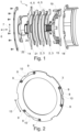
- Fig. 1 shows an example and schematic of the structure of a multi-plate clutch 1, which is designed in particular as a dry multi-plate clutch 1.
- This includes, among other things, a plurality of outer disks 2, which are designed here as steel disks 3, and a corresponding plurality of inner disks 4, which are designed here as lining disks 5.
- the multi-plate clutch 1 has an axial direction 6 and a radial direction 7.
- the outer slats 2 are suspended on the outside in the radial direction 7 and can be moved in the axial direction 6.
- the inner slats 4 are suspended on the inside in the radial direction 7 and can be moved in the axial direction 6.
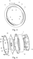
- Fig. 2 shows an example of a steel lamella 3 that can be used as an outer lamella 2.
- This has three leaf springs 8, which are evenly distributed in the circumferential direction, i.e. are designed in such a way that adjacent leaf springs 8 enclose the same angles with one another.
- the leaf springs 8 are made of spring steel and are connected to the steel lamella 3 via hollow rivets 9. Both ends of each leaf spring 8, which are spaced apart in a circumferential direction 13, are connected to the steel plate 3 by the hollow rivets 9.
- Each leaf spring 8 has a recess 10, the function of which is explained below.
- Fig. 3 shows an example of a lining plate 5 that can be used as an inner plate 4.
- This has two friction plates 11, which are formed on opposite sides of a lining carrier 12.
- the covering plate 5 preferably has three leaf springs 8.
- the leaf springs 8 are formed in one piece with the lining carrier 12 in that both ends of each leaf spring 8, which are spaced apart from one another in the circumferential direction 13, merge into the lining carrier 12.
- Each leaf spring 8 has a recess 10, the function of which is explained below.
- the multi-plate clutch 1 also has a driving ring 14 on which the inner plates 4 are suspended to transmit torque.
- the outer slats 5 are suspended on a rotor pot 15.
- torque can be transmitted between the driving ring 14 via the inner plates 4 and the outer plates 5 to the rotor pot 15 and vice versa, depending on whether there is a pulling or pushing operation.
- the rotor pot 15 has a plurality of arms 16 which extend from the rotor pot in the axial direction 6. These arms 16, of which, for example, three are formed per rotor pot 15, have several functions.
- the arms 16 serve to support the outer slats 5 by interacting with the recesses 10 in the leaf springs 8 of the outer slats 5 (cf. Fig. 2 ).
- the recesses 10 are U-shaped, so that a corresponding contact surface results in both circumferential directions 13.
- the recesses 10 can also be O-shaped.
- the multi-plate clutch 1 When the multi-plate clutch is engaged, a relative movement occurs between the inner plates 4 and the driving ring 14 or between the outer plates 2 and the rotor carrier 18, which takes place, for example, via a pressure pot 19.
- the leaf springs 8 generate a relatively large axial movement of the corresponding inner plate 4 and outer plate 2 even with minimal friction during the relative movement; a sliding movement, for example between the lining carrier 12 and the corresponding leaf spring guides 20, is avoided.
- the presence of a small amount of friction during the relative movement between arms 16 and recesses 10 causes a significantly larger movement of the outer plate 2 in the axial direction 6.
- a sliding movement between arms 16 and recesses 10 is avoided.
- the multi-plate clutch 1 has a pressure plate 21 which supports the contact pressure.
- the pressure plate 21 is screwed to the rotor carrier 18.
- the multi-plate clutch 1 includes a mounting ring 22 for fixing the pressure plate 21 on the rotor carrier 18.
- Fig. 4 shows another view of the multi-plate clutch 1 with mounting ring 22, pressure plate 21, rotor carrier 18 and rotor pot 15.
- Fig. 5 to 7 show various perspective views of the assembled multi-plate clutch 1. Reference is made to the statements made above.
- Fig. 8 shows schematically a hybrid drive train 23, in particular of a motor vehicle with an internal combustion engine 24, which is connected via a crankshaft 25 to the multi-plate clutch 1, which is designed here as a K0 or separating clutch for separating and connecting the internal combustion engine 24 from the hybrid drive train 23.
- the multi-plate clutch 1 is designed concentrically with an electric machine 26. Torque can be transmitted to the wheels of the motor vehicle, not shown, via an output shaft 27.
- the output shaft 27 can be connected to the multi-plate clutch 1 and the electric machine 26.
- the multi-plate clutch 1 is integrated in particular into a rotor of the electric machine 26.
- the electric machine 26 is preferably an electric motor and/or an electric generator.
- the steel slats 3 and lining slats 5 can in principle be arranged in both directions (inside and outside). However, this description only deals with the case where the lining lamellae (cf. Fig. 3 ) are located on the inside (inner disks 4) and thus absorb the engine torque from the driving ring 14) and onto the external steel disks 3 (outer disks 2) ( Fig.2 ) transmitted. This is done via a carrier plate (lining carrier 12), which is located between two linings (friction plates 11) to form a so-called lining plate 5 (cf. Fig.3 ) is glued. There are at least three spring elements in the carrier plate (lining carrier 12).
- the spring elements should have the lowest possible axial rigidity in order to enable axial movement of the lamella with minimal sliding friction. This prevents a sliding movement between the carrier plate (lining carrier 12) and the leaf spring guide 20.
- the steel lamella 3 is stored on the outside in a similar way.
- the spring elements (leaf springs 8) are designed as individual leaf springs 8 and are riveted to the respective steel lamella 3 (cf. the hollow rivets 9 in Fig. 3 ).
- gluing to the carrier plate (lining carrier 12) also appears possible.
- the clutch can consist of several plate packs connected in series.
- the clutch (multi-plate clutch 1) is actuated most effectively without a gear ratio, i.e. directly via a pressure pot 19 from the release bearing. However, it is also possible to generate a translation using a disc spring or lever spring.
- the contact force is supported at the opposite axial end by a pressure plate 21 screwed to the rotor carrier 18. This saves a weld seam between the rotor pot 15 and the rotor carrier 18 and at the same time enables the slats to be easily assembled/dismantled.
- axial grooves 17 are made on the inner diameter of the rotor carrier 18.
- Corresponding arms 16 of the rotor pot 15 run through these, which also serve to support the steel plate leaf springs (leaf springs 8 of the steel plate 3).
Landscapes
- Engineering & Computer Science (AREA)
- General Engineering & Computer Science (AREA)
- Mechanical Engineering (AREA)
- Mechanical Operated Clutches (AREA)
- Hybrid Electric Vehicles (AREA)
Description
- Die vorliegende Erfindung betrifft eine Lamellenkupplung, insbesondere eine trockene Lamellenkupplung, insbesondere für einen hybriden Antriebsstrang, sowie einen hybriden Antriebsstrang mit einer trockenen K0-Lamellenkupplung zum An- und Abkoppeln eines Verbrennungsmotors und/oder mit einer in den Rotor einer elektrischen Maschine, wie eines Elektromotors oder eines Generators, integrierten trockenen Lamellenkupplung.
- Lamellenkupplungen sind in der Regel Mehrscheibenkupplungen, in denen die Lamellen in axialer Richtung frei beweglich gelagert sind. Beim Öffnen und Schließen der Kupplung werden sie innerhalb einer passenden Außen- oder Innenverzahnung axial verschoben. Neben der Verzahnung der Lamellen auf dem zugehörigen Lamellenträger sind sonst keine weiteren Zentrierungen oder Positionierungen der Lamellen vorhanden. In jedem Zahn besteht ein Flächenkontakt zwischen den beteiligten Bauteilen, so dass es (bedingt durch Toleranzen) leicht zu einer ungünstigen Positionierung bzw. Verklemmung kommen kann. Dies führt zu hohen Reibverlusten in der Kupplung. Zudem ist die Geometrie des Lamellenträger sehr komplex, was zu hohen Herstellkosten führt.
- Aus der
DE 10 2008 006 155 A1 ist eine Lamellenkupplung mit zumindest einer in radialer Richtung außen eingehängten und in axialer Richtung verschiebbaren Außenlamelle und zumindest einer in radialer Richtung innen eingehängten und in axialer Richtung verschiebbaren Innenlamelle bekannt, wobei die Außenlamelle über eine Mehrzahl im Außenumfang verteilt angeordneter Blattfedern drehmomentübertragend an einem Rotor-Topf eingehängt ist. - Es ist Aufgabe der vorliegenden Erfindung, eine Lamellenkupplung, insbesondere eine trockene Lamellenkupplung, sowie einen hybriden Antriebsstrang mit einer trockenen Lamellenkupplung mit geringen Reibverlusten und geringen Herstellkosten anzugeben.
- Erfindungsgemäß gelöst wird diese Aufgabe durch eine Lamellenkupplung, insbesondere eine trockene Lamellenkupplung, und einen hybriden Antriebsstrang gemäß den unabhängigen Patentansprüchen. Bevorzugte Ausführungsbeispiele sind in den abhängigen Patentansprüchen dargelegt.
- Die erfindungsgemäße Lamellenkupplung, insbesondere trockene Lamellenkupplung, insbesondere für einen hybriden Antriebsstrang insbesondere eines Kraftfahrzeuges, weist zumindest eine in radialer Richtung außen eingehängte und in axialer Richtung verschiebbare Außenlamelle und zumindest eine in radialer Richtung innen eingehängte und in axialer Richtung verschiebbare Innenlamelle auf, wobei die Außenlamelle über eine Mehrzahl im Außenumfang verteilt angeordneter Blattfedern drehmomentübertragend an einem Rotor-Topf eingehängt ist, und/oder wobei die Innenlamellen über eine Mehrzahl im Innenumfang verteilt angeordneter Blattfedern drehmomentübertragend an einem Mitnehmerkranz eingehängt ist.
- Bevorzugt ist die mindestens eine Außenlamelle als Stahllamelle(n) und die mindestens eine Innenlamelle als Belaglamelle(n) ausgebildet.
- Alternativ ist die mindestens eine Außenlamelle als Belaglamelle(n) und die mindestens eine Innenlamelle als Stahllamelle(n) ausgebildet.
- Die Belaglamelle weist dabei in axialer Richtung auf mindestens einer Seite, bevorzugt auf beiden Seiten, Reiblamellen auf, also Reibflächen, die insbesondere mit benachbarten Stahllamellen in reibenden Eingriff gebracht werden. Bevorzugt ist dabei die Belaglamelle durch zwei Reiblamellen gebildet, die stoffschlüssig mit einem Trägerblech (Belagträger) verbunden sind, insbesondere verklebt. Ebenso bevorzugt ist auch eine Vernietung der Reiblamellen mit dem Belagträger bzw. Trägerblech.
- Kerngedanke der Erfindung ist es, die axiale Bewegung der trockenen Lamellen beim Öffnen und Schließen der Kupplung reibungsfrei bzw. nahezu reibungsfrei zu realisieren. Dazu werden diese jeweils auf mindestens drei Blattfedern bzw.
- Blattfederpaketen gelagert. Die Blattfederkraft/-steifigkeit ist dabei sehr klein anzustreben. Gleichzeitig muss jedoch eine ausreichende Übertragungssicherheit des anliegenden Momentes gegeben sein. Während der Momentenübertragung (also bei ganz oder fast vollständig geschlossener Kupplung) wird die Verschiebereibung größer als die axiale Blattfederkraft und die Blattfeder kann nicht mehr in ihrer Führung gleiten (= reiben). Die Lamelle kann sich jedoch aufgrund der entstehenden Blattfederdurchbiegung weiterhin axial bewegen.
- Hierdurch wird die Reibung der Lamellen in axialer Richtung und werden damit die entstehenden Reibverluste der Lamellenkupplung reduziert.
- Die Blattfedern sind einteilig mit einem Belagträger einer innen oder außen eingehängten Belaglamelle ausgebildet, indem beide in Umfangsrichtung voneinander beabstandeten Enden einer jeden Blattfeder in den Belagträger übergehen. Somit sind die Blattfedern als axiale Federelemente direkt in den Belagträger bzw. das Trägerblech integriert.
- Gemäß einer vorteilhaften Ausgestaltung sind weitere der Blattfedern mit einer außen oder innen eingehängten Stahllamelle verbunden, vorzugsweise vernietet, indem beide in Umfangsrichtung voneinander beabstandeten Enden einer jeden Blattfeder mit der Stahllamelle verbunden, vorzugsweise vernietet, sind.
- Hierdurch ist ein einfacher Aufbau einer Belaglamelle und/oder Stahllamelle möglich. Bevorzugt ist eine Ausgestaltung, bei der die Blattfedern an der Außenlamelle und/oder der Innenlamelle in Umfangsrichtung gleichmäßig verteilt sind.
- Dies ermöglicht eine gleichmäßige Verteilung der entsprechenden Federkräfte der Blattfedern über den Umfang der Außenlamelle und/oder Innenlamelle, was das Risiko einer erhöhten Reibung bis hin zu einem möglichen Verklemmen der Außenlamellen und/oder der Innenlamellen weiter reduziert.
- Besonders bevorzugt hat sich eine symmetrische Ausgestaltung von vorzugsweise mindestens drei Blattfedern pro Außenlamelle oder Innenlamelle herausgestellt, da dadurch eine gleichmäßige Verteilung der Federkräfte der Blattfedern in Umfangsrichtung erreicht werden kann und eine Unwucht vermieden werden kann. Bei Lamellenpaketen sind diese aus einer entsprechenden Zahl von identischen Außenlamellen oder Innenlamellen ausgebildet, so dass sich mindestens drei Blattfederpakete pro Lamellenpaket ausbilden.
- Gemäß einer vorteilhaften Ausgestaltung ist ein Rotor-Träger zur Verbindung dem Rotor-Topf ausgebildet, der in radialer Richtung innen axiale Nuten aufweist, in die entsprechende Arme des Rotor-Topfes eingreifen.
- Durch das Zusammenwirken von Nuten und Armen kann die Übertragung von Drehmoment zwischen Rotor-Topf und Rotor-Träger erfolgen. Eine Schweißverbindung zwischen Rotor-Topf und Rotor-Träger kann dadurch unterbleiben.
- Besonders vorteilhaft ist in diesem Zusammenhang, dass die Arme des Rotor-Topfes zur Lagerung der Blattfedern der Außenlamellen dienen, wobei die Blattfedern zu den Armen korrespondierende Ausnehmungen aufweisen.
- Dies ermöglicht eine einfache Montage und Demontage der entsprechenden Außenlamellen.
- Weiterhin wird ein hybrider Antriebsstrang mit einer Lamellenkupplung nach der vorliegenden Erfindung vorgeschlagen, die als K0-Kupplung zum An- und Abkoppeln eines Verbrennungsmotors ausgebildet ist, und/oder die in den Rotor einer elektrischen Maschine, wie eines Elektromotors oder eines Generators, integriert ist.
- Vorsorglich sei angemerkt, dass die hier verwendeten Zahlwörter ("erste", "zweite",...) vorrangig (nur) zur Unterscheidung von mehreren gleichartigen Gegenständen, Größen oder Prozessen dienen, also insbesondere keine Abhängigkeit und/oder Reihenfolge dieser Gegenstände, Größen oder Prozesse zueinander zwingend vorgeben. Sollte eine Abhängigkeit und/oder Reihenfolge erforderlich sein, ist dies hier explizit angegeben oder es ergibt sich offensichtlich für den Fachmann beim Studium der konkret beschriebenen Ausgestaltung.
- Die Erfindung sowie das technische Umfeld werden nachfolgend anhand der Figuren näher erläutert. Es ist darauf hinzuweisen, dass die Erfindung durch die gezeigten Ausführungsbeispiele nicht beschränkt werden soll. Insbesondere ist es, soweit nicht explizit anders dargestellt, auch möglich, Teilaspekte der in den Figuren erläuterten Sachverhalte zu extrahieren und mit anderen Bestandteilen und Erkenntnissen aus der vorliegenden Beschreibung und/oder Figuren zu kombinieren. Insbesondere ist darauf hinzuweisen, dass die Figuren und insbesondere die dargestellten Größenverhältnisse nur schematisch sind. Gleiche Bezugszeichen bezeichnen gleiche Gegenstände, so dass ggf. Erläuterungen aus anderen Figuren ergänzend herangezogen werden können. Es zeigen:
- Fig. 1:
- ein Beispiel eines Aufbaus einer Lamellenkupplung;
- Fig. 2:
- ein Beispiel eines Aufbaus einer Stahllamelle;
- Fig. 3
- ein Beispiel eines Aufbaus einer Belaglamelle;
- Fig. 4
- eine weitere Ansicht des Beispiels einer Lamellenkupplung; und
- Fig. 5
- eine erste perspektivische Ansicht der montierten Lamellenkupplung;
- Fig. 6
- eine zweite perspektivische Ansicht der montierten Lamellenkupplung;
- Fig. 7
- eine dritte perspektivische Ansicht der montierten Lamellenkupplung; und
- Fig. 8
- einen hybriden Antriebsstrang eines Kraftfahrzeugs.
-
Fig. 1 zeigt exemplarisch und schematisch den Aufbau einer Lamellenkupplung 1, die insbesondere als trockene Lamellenkupplung 1 ausgebildet ist. Diese umfasst unter anderem eine Mehrzahl von Außenlamellen 2, die hier als Stahllamellen 3 ausgeführt sind und eine entsprechende Mehrzahl von Innenlamellen 4, die hier als Belaglamellen 5 ausgebildet sind. Die Lamellenkupplung 1 weist eine axiale Richtung 6 und eine radiale Richtung 7 auf. Die Außenlamellen 2 sind in radialer Richtung 7 außen eingehängt und in axialer Richtung 6 verschiebbar. Die Innenlamellen 4 sind in radialer Richtung 7 innen eingehängt und in axialer Richtung 6 verschiebbar. Durch die Verlagerung der Innenlamellen 4 und der Außenlamellen 2 relativ zu einander in axialer Richtung 6 können in axialer Richtung 6 benachbarte Innenlamellen 4 und Außenlamellen 2 in Reibschluss miteinander gebracht werden, so dass Drehmoment von den Innenlamellen 4 zu den Außenlamellen 2 und umgekehrt übertragen werden kann. -
Fig. 2 zeigt ein Beispiel einer als Außenlamelle 2 einsetzbaren Stahllamelle 3. Diese weist drei Blattfedern 8 auf, die in Umfangsrichtung gleichmäßig verteilt sind, also so ausgebildet sind, dass jeweils benachbarte Blattfedern 8 gleiche Winkel miteinander einschließen. Die Blattfedern 8 sind aus einem Federstahl ausgebildet und werden über Hohlniete 9 mit der Stahllamelle 3 verbunden. Beide in einer Umfangsrichtung 13 voneinander beabstandeten Enden einer jeden Blattfeder 8 sind mit der Stahllamelle 3 durch die Hohlnieten 9 verbunden. Jede Blattfeder 8 weist eine Ausnehmung 10 auf, deren Funktion weiter unten erläutert wird. -
Fig. 3 zeigt ein Beispiel einer als Innenlamelle 4 einsetzbaren Belaglamelle 5. Diese weist zwei Reiblamellen 11 auf, die auf gegenüberliegenden Seiten eines Belagträgers 12 ausgebildet sind. Die Belaglamelle 5 weist vorzugsweise drei Blattfedern 8 auf. Die Blattfedern 8 sind einteilig mit dem Belagträger 12 ausgebildet, indem beide in Umfangsrichtung 13 voneinander beabstandeten Enden einer jeden Blattfeder 8 in den Belagträger 12 übergehen. Jede Blattfeder 8 weist eine Ausnehmung 10 auf, deren Funktion weiter unten erläutert wird. - Im Folgenden wird wieder auf
Fig. 1 Bezug genommen. Die Lamellenkupplung 1 weist ferner einen Mitnehmerkranz 14 auf, an dem die Innenlamellen 4 drehmomentübertragend eingehängt sind. Die Außenlamellen 5 sind an einem Rotor-Topf 15 eingehängt. Im Betrieb kann im eingerückten Zustand der Lamellenkupplung 1 Drehmoment zwischen Mitnehmerkranz 14 über die Innenlamellen 4 und die Außenlamellen 5 auf den Rotor-Topf 15 übertragen werden und umgekehrt, je nachdem, ob ein Zug- oder Schubbetrieb vorliegt. Der Rotor-Topf 15 weist mehrere Arme 16 auf, die sich vom Rotor-Topf in axialer Richtung 6 erstrecken. Diese Arme 16, von denen beispielsweise drei pro Rotor-Topf 15 ausgebildet sind, haben dabei mehrere Funktionen. Durch Zusammenwirken mit entsprechenden axialen Nuten 17 eines Rotor-Trägers 18, in die die Arme 16 eingeschoben werden, kann Drehmoment zwischen Rotor-Topf 15 und Rotor-Träger 18 übertragen werden. Weiterhin dienen die Arme 16 der Lagerung der Außenlamellen 5, in dem sie mit den Ausnehmungen 10 der Blattfedern 8 der Außenlamellen 5 zusammenwirken (vgl.Fig. 2 ). - Im eingerückten Zustand erfolgt die Drehmomenteinleitung bzw. -ausleitung über die Ausnehmungen 10. Um sowohl im Schub- als auch im Zugbetrieb eine Drehmomentübertragungen zu ermöglichen, sind die Ausnehmungen 10 U-förmig ausgebildet, so dass sich in beide Umfangsrichtungen 13 eine entsprechende Anlagefläche ergibt. Alternativ können die Ausnehmungen 10 auch O-förmig ausgebildet werden.
- Beim Einrücken der Lamellenkupplung erfolgt eine Relativbewegung zwischen Innenlamellen 4 und Mitnehmerkranz 14 bzw. zwischen Außenlamellen 2 und Rotor-Träger 18, die beispielsweise über einen Drucktopf 19 erfolgt. Durch die Blattfedern 8 wird bereits bei minimaler Reibung bei der Relativbewegung eine relativ große axiale Bewegung der entsprechenden Innenlamelle 4 und Außenlamelle 2 erzeugt, eine Gleitbewegung beispielsweise zwischen dem Belagträger 12 und den entsprechenden Blattfederführungen 20 wird vermieden. Analog bewirkt bereits das Vorliegen einer kleinen Reibung bei der Relativbewegung zwischen Armen 16 und Ausnehmungen 10 eine deutlich größere Bewegung der Außenlamelle 2 in axialer Richtung 6 erfolgt. Auch hier wird eine Gleitbewegung zwischen Armen 16 und Ausnehmungen 10 vermieden. Weiterhin weist die Lamellenkupplung 1 eine Anpressplatte 21 auf, die die Anpresskraft abstützt. Die Anpressplatte 21 ist dabei mit dem Rotor-Träger 18 verschraubt. Weiterhin umfasst die Lamellenkupplung 1 einen Montagering 22 zur Fixierung der Anpressplatte 21 am Rotor-Träger 18.
-
Fig. 4 zeigt eine weitere Ansicht der Lamellenkupplung 1 mit Montagering 22, Anpressplatte 21, Rotor-Träger 18 und Rotor-Topf 15. -
Fig. 5 bis 7 zeigen verschiedene perspektivische Ansichten der montierten Lamellenkupplung 1. Es wird auf die oben gemachten Ausführungen verwiesen. -
Fig. 8 zeigt schematisch einen hybriden Antriebsstrang 23 insbesondere eines Kraftfahrzeuges mit einem Verbrennungsmotor 24, der über eine Kurbelwelle 25 mit der Lamellenkupplung 1 verbunden ist, die hier als K0- oder Trennkupplung zum Trennen und Verbinden des Verbrennungsmotors 24 vom hybriden Antriebsstrang 23 ausgebildet ist. Die Lamellenkupplung 1 ist konzentrisch mit einer elektrischem Maschine 26 ausgebildet. Über eine Ausgangswelle 27 kann Drehmoment auf die nicht gezeigten Räder des Kraftfahrzeuges übertragen werden. Die Ausgangswelle 27 ist dabei mit der Lamellenkupplung 1 und der elektrischen Maschine 26 verbindbar. Die Lamellenkupplung 1 ist insbesondere in einen Rotor der elektrischen Maschine 26 integriert. Die elektrische Maschine 26 ist dabei bevorzugt ein Elektromotor und/oder ein elektrischer Generator. - Die Anordnung von Stahllamellen 3 und Belaglamellen 5 kann prinzipiell in beide Richtungen erfolgen (innen und außen). In der vorliegenden Beschreibung wird jedoch nur auf den Fall eingegangen, dass die Belaglamellen (vgl.
Fig. 3 ) innen liegen (Innenlamellen 4) und somit das Motormoment vom Mitnehmerkranz14) aufnehmen und auf die außenliegenden Stahllamellen 3 (Außenlamellen 2) (Fig.2 ) übertragen. Dies geschieht über ein Trägerblech (Belagträger 12), das jeweils zwischen zwei Belägen (Reiblamellen 11) zu einer sogenannten Belaglamelle 5 (vgl.Fig.3 ) verklebt wird. Im Trägerblech (Belagträger 12) befinden sich mindestens drei Federelemente (Blattfedern 8) mit innenliegenden Aussparungen (Ausnehmungen 10) in Umfangsrichtung 13. In diesen Aussparungen (Ausnehmungen 10) wird das Moment auf das Trägerblech (Belagträger 12) und damit die Reiblamellen 11 eingeleitet. Das Moment kann dabei in beide Richtungen übertragen werden, da eine U-förmiger Kontakt (möglich wäre je nach Bauraumverhältnissen auch ein O-förmiger Kontakt) vorhanden ist. Die Federelemente (Blattfedern 8) sollten eine möglichst geringe axiale Steifigkeit aufweisen, um bereits bei minimaler Verschiebereibung eine axiale Bewegung der Lamelle zu ermöglichen. Dadurch wird eine Gleitbewegung zwischen Trägerblech (Belagträger 12) und Blattfederführung 20 vermieden. - Die Stahllamelle 3 wird nach außen hin in ähnlicher Weise gelagert. Die Federelemente (Blattfedern 8) sind als einzelne Blattfedern 8 ausgeführt und auf der jeweiligen Stahllamelle 3 vernietet (vgl. die Hohlnieten 9 in
Fig. 3 ). Ein Verkleben auf dem Trägerblech (Belagträger 12) erscheint jedoch auch möglich. - Je nach Anforderung und notwendiger Momentenkapazität kann die Kupplung (Lamellenkupplung 1) aus mehreren hintereinandergeschalteten Lamellenpaketen bestehen.
- Betätigt wird die Kupplung (Lamellenkupplung 1) am effektivsten ohne Übersetzung, also direkt über einen Drucktopf 19 vom Ausrücklager. Es ist jedoch auch möglich mithilfe einer Tellerfeder oder Hebelfeder eine Übersetzung zu generieren.
- Die Anpresskraft wird am gegenüberliegenden axialen Ende durch eine an den Rotor-Träger 18 verschraubte Anpressplatte 21 abgestützt. Dies erspart eine Schweißnaht zwischen Rotor-Topf 15 und Rotor-Träger 18 und ermöglicht gleichzeitig eine einfache Montage/Demontage der Lamellen.
- Zur Momentenübertragung zwischen Rotor-Topf 15 und Rotor-Träger 18 sind axiale Nuten 17 am Innendurchmesser des Rotor-Trägers 18 eingebracht. Durch diese verlaufen entsprechende Arme 16 des Rotor-Topfes 15, die gleichzeitig auch zur Lagerung der Stahllamellen-Blattfedern (Blattfedern 8 der Stahllamellen 3) dienen.
-
- 1
- Lamellenkupplung
- 2
- Außenlamelle
- 3
- Stahllamelle
- 4
- Innenlamelle
- 5
- Belaglamelle
- 6
- Axiale Richtung
- 7
- Radiale Richtung
- 8
- Blattfeder
- 9
- Hohlniet
- 10
- Ausnehmung
- 11
- Reiblamelle
- 12
- Belagträger
- 13
- Umfangsrichtung
- 14
- Mitnehmerkranz
- 15
- Rotor-Topf
- 16
- Arm
- 17
- Nut
- 18
- Rotor-Träger
- 19
- Drucktopf
- 20
- Blattfederführung
- 21
- Anpressplatte
- 22
- Montagering
- 23
- Hybrider Antriebstrang
- 24
- Verbrennungsmotor
- 25
- Kurbelwelle
- 26
- Elektrische Maschine
- 27
- Ausgangswelle
Claims (9)
- Lamellenkupplung (1), insbesondere trockene Lamellenkupplung, insbesondere für einen hybriden Antriebsstrang (23), mit zumindest einer in radialer Richtung (7) außen eingehängten und in axialer Richtung (6) verschiebbaren Außenlamelle (2) und zumindest einer in radialer Richtung (7) innen eingehängten und in axialer Richtung (6) verschiebbaren Innenlamelle (4),wobei die Außenlamelle (2) über eine Mehrzahl im Außenumfang verteilt angeordneter Blattfedern (8) drehmomentübertragend an einem Rotor-Topf (15) eingehängt ist und/oder die Innenlamellen (2) über eine Mehrzahl im Innenumfang verteilt angeordneter Blattfedern (8) drehmomentübertragend an einem Mitnehmerkranz (14) eingehängt ist,dadurch gekennzeichnet, dass mindestens zwei der Blattfedern (8) einteilig mit einem Belagträger (12) einer innen oder außen eingehängten Belaglamelle (5) ausgebildet sind, indem beide in Umfangsrichtung (13) voneinander beabstandeten Enden einer jeden Blattfeder (8) in den Belagträger (12) übergehen.
- Lamellenkupplung (1) nach Anspruch 1, bei der die mindestens eine Außenlamelle (2) als Stahllamelle(n) (3) und die mindestens eine Innenlamelle (4) als Belaglamelle(n) (5) ausgebildet sind.
- Lamellenkupplung (1) nach Anspruch 1, bei der die mindestens eine Außenlamelle (2) als Belaglamelle(n) (5) und die mindestens eine Innenlamelle (4) als Stahllamelle(n) (3) ausgebildet sind.
- Lamellenkupplung (1) nach einem der vorhergehenden Ansprüche, wobei mindestens zwei weitere Blattfedern (8) mit einer außen oder innen eingehängten Stahllamelle (3) verbunden, vorzugsweise vernietet, sind, indem beide in Umfangsrichtung (13) voneinander beabstandeten Enden einer jeden Blattfeder (8) mit der Stahllamelle (3) verbunden, vorzugsweise vernietet, sind.
- Lamellenkupplung (1) nach einem der vorherigen Ansprüche, bei der die Blattfedern (8) an der Außenlamelle (2) und/oder der Innenlamelle (4) in Umfangsrichtung (13) gleichmäßig verteilt sind.
- Lamellenkupplung (1) nach einem der vorherigen Ansprüche, bei der pro Außenlamelle (2) oder Innenlamelle (4) mindestens drei Blattfedern (8) ausgebildet sind.
- Lamellenkupplung (1) nach einem der vorhergehenden Ansprüche, bei der ein Rotor-Träger (15) ausgebildet ist, der in radialer Richtung (7) innen axiale Nuten (17) aufweist, in die entsprechende Arme (16) des Rotor-Topfes (15) eingreifen.
- Lamellenkupplung (1) nach Anspruch 7, bei der die Arme (16) des Rotor-Topfes (15) zur Lagerung der Blattfedern (8) der Außenlamellen (2) dienen, wobei die Blattfedern (8) zu den Armen (16) korrespondierende Ausnehmungen (10) aufweisen.
- Hybrider Antriebsstrang (23) mit einer Lamellenkupplung (1) nach einem der vorhergehenden Ansprüche, die als K0-Kupplung zum An- und Abkoppeln eines Verbrennungsmotors (24) ausgebildet ist, und/oder die in den Rotor einer elektrischen Maschine (26), wie eines Elektromotors oder eines Generators, integriert ist.
Applications Claiming Priority (3)
| Application Number | Priority Date | Filing Date | Title |
|---|---|---|---|
| DE102019109418 | 2019-04-10 | ||
| DE102019112566.9A DE102019112566A1 (de) | 2019-04-10 | 2019-05-14 | Lamellenkupplung, insbesondere trockene Lamellenkupplung, insbesondere für hybriden Antriebsstrang |
| PCT/DE2020/100166 WO2020207524A1 (de) | 2019-04-10 | 2020-03-10 | Lamellenkupplung, insbesondere trockene lamellenkupplung, insbesondere für hybriden antriebsstrang |
Publications (2)
| Publication Number | Publication Date |
|---|---|
| EP3953595A1 EP3953595A1 (de) | 2022-02-16 |
| EP3953595B1 true EP3953595B1 (de) | 2024-01-17 |
Family
ID=72613669
Family Applications (1)
| Application Number | Title | Priority Date | Filing Date |
|---|---|---|---|
| EP20714472.6A Active EP3953595B1 (de) | 2019-04-10 | 2020-03-10 | Lamellenkupplung, insbesondere trockene lamellenkupplung, insbesondere für hybriden antriebsstrang |
Country Status (7)
| Country | Link |
|---|---|
| US (1) | US11821469B2 (de) |
| EP (1) | EP3953595B1 (de) |
| JP (1) | JP7472166B2 (de) |
| KR (1) | KR20210149687A (de) |
| CN (1) | CN113710914A (de) |
| DE (1) | DE102019112566A1 (de) |
| WO (1) | WO2020207524A1 (de) |
Families Citing this family (1)
| Publication number | Priority date | Publication date | Assignee | Title |
|---|---|---|---|---|
| DE102019127238A1 (de) | 2019-04-10 | 2020-10-15 | Schaeffler Technologies AG & Co. KG | Lamellenkupplung, insbesondere für einen Hybrid-Antriebsstrang |
Family Cites Families (13)
| Publication number | Priority date | Publication date | Assignee | Title |
|---|---|---|---|---|
| US2174240A (en) * | 1937-11-10 | 1939-09-26 | Carlyle Johnson Machine Co | Clutch |
| DE3100586A1 (de) * | 1981-01-10 | 1982-08-26 | Alfred Teves Gmbh, 6000 Frankfurt | Vorrichtung zur lagerung eines scheibenfoermigen reibelements in einem traegerteil fuer eine brems- oder kupplungseinrichtung |
| JPS5986716A (ja) | 1982-11-08 | 1984-05-19 | Yamaha Motor Co Ltd | 多板式クラツチ |
| DE3320977C1 (de) | 1983-06-10 | 1984-12-20 | Prodan Antriebselemente GmbH, 7033 Herrenberg | Lamellenkupplung |
| DE10020262B4 (de) * | 1999-04-28 | 2012-04-12 | Schaeffler Technologies Gmbh & Co. Kg | Lamellenkupplung |
| FR2865010B1 (fr) * | 2004-01-09 | 2006-03-03 | Valeo Embrayages | Embrayage a friction, notamment pour vehicule automobile, comportant des moyens de frottement differencies |
| FR2894637B1 (fr) * | 2005-12-13 | 2008-02-15 | Valeo Materiaux De Friction Sa | Dispositif de friction perfectionne pour un embrayage, notamment de vehicule automobile |
| DE102008006155A1 (de) | 2008-01-26 | 2009-07-30 | Daimler Ag | Lamellenkupplung |
| JP6094110B2 (ja) | 2012-09-20 | 2017-03-15 | 日産自動車株式会社 | 車両の動力伝達装置 |
| DE112016001198T5 (de) * | 2015-03-13 | 2017-11-30 | Schaeffler Technologies AG & Co. KG | Kupplungsscheibe mit verringertem Schlupf |
| DE112016004810A5 (de) * | 2015-10-22 | 2018-06-28 | Schaeffler Technologies AG & Co. KG | Drehschwingungsdämpfer und Hybrid-Antriebsstrang |
| DE102016207116B3 (de) * | 2016-04-27 | 2017-05-04 | Schaeffler Technologies AG & Co. KG | Kupplung mit Momentenflussaufteilung zur partiellen Verstärkung |
| DE102017130350A1 (de) | 2017-12-18 | 2019-06-19 | Schaeffler Technologies AG & Co. KG | Drehmomentübertragungseinheit, elektrische Antriebseinheit und Antriebsstrang |
-
2019
- 2019-05-14 DE DE102019112566.9A patent/DE102019112566A1/de not_active Withdrawn
-
2020
- 2020-03-10 CN CN202080026533.0A patent/CN113710914A/zh active Pending
- 2020-03-10 EP EP20714472.6A patent/EP3953595B1/de active Active
- 2020-03-10 US US17/436,672 patent/US11821469B2/en active Active
- 2020-03-10 WO PCT/DE2020/100166 patent/WO2020207524A1/de not_active Ceased
- 2020-03-10 JP JP2021559945A patent/JP7472166B2/ja active Active
- 2020-03-10 KR KR1020217024650A patent/KR20210149687A/ko active Pending
Also Published As
| Publication number | Publication date |
|---|---|
| JP2022527397A (ja) | 2022-06-01 |
| CN113710914A (zh) | 2021-11-26 |
| US11821469B2 (en) | 2023-11-21 |
| DE102019112566A1 (de) | 2020-10-15 |
| EP3953595A1 (de) | 2022-02-16 |
| KR20210149687A (ko) | 2021-12-09 |
| WO2020207524A1 (de) | 2020-10-15 |
| JP7472166B2 (ja) | 2024-04-22 |
| US20220136566A1 (en) | 2022-05-05 |
Similar Documents
| Publication | Publication Date | Title |
|---|---|---|
| EP3337998B1 (de) | Kupplungseinrichtung für hybridantrieb | |
| EP3559494B1 (de) | Hybridmodul und antriebsanordnung für ein kraftfahrzeug | |
| EP3198160B1 (de) | Zuschaltkupplung für hybriden antriebsstrang mit momentenfühler | |
| EP3593002B1 (de) | Kupplungseinrichtung und hybridmodul | |
| DE102009057353A1 (de) | Lamellenkupplung mit einer Federeinrichtung | |
| EP3135522A1 (de) | Hybridmodul und verfahren zum übertragen eines drehmomentes in einem triebstrang eines kraftfahrzeuges | |
| EP3655274B1 (de) | Hybridmodul | |
| DE102008043211A1 (de) | Torsionsschwingungsdämpferanordnung, insbesondere für den Antriebsstrang eines Fahrzeugs | |
| WO2015144164A1 (de) | Federelement für eine antriebseinheit einer weggesteuerten nachstelleinrichtung | |
| WO2015144165A1 (de) | Nachstelleinrichtung für eine reibkupplung | |
| DE102017130266A1 (de) | Hybridmodul | |
| WO2020216394A1 (de) | Hybridmodul sowie antriebsstrang für ein kraftfahrzeug | |
| EP1862685A1 (de) | Drehmomentübertragungsanordnung für den Antriebsstrang eines Fahrzeugs | |
| WO2022112123A1 (de) | Trenneinrichtung sowie antriebsstrang und fahrzeug mit dieser | |
| DE102017130480A1 (de) | Einschubmodul, Hybridmodul, Antriebsstrang für ein Kraftfahrzeug und Verfahren zum Zusammenbauen eines Antriebsstrangs | |
| DE102019112566A1 (de) | Lamellenkupplung, insbesondere trockene Lamellenkupplung, insbesondere für hybriden Antriebsstrang | |
| DE102012211706A1 (de) | Reibungskupplung | |
| DE102019002850A1 (de) | Kupplungseinrichtung und Antriebsstrang mit einer solchen Kupplungseinrichtung | |
| EP3833885B1 (de) | Lamellenpaket mit gezielt eingebrachter axialer weichheit | |
| DE102017130269A1 (de) | Hybridmodul | |
| EP3123053B1 (de) | Nachstelleinrichtung für eine reibkupplung | |
| EP3615824A1 (de) | Kupplungsvorrichtung für einen antriebsstrang eines fahrzeuges | |
| DE102018131319B3 (de) | Drehmomentbegrenzer mit zumindest einem Abstandsblech und/oder Abstandsbolzen zur Zentrierung einer daran angrenzenden Komponente des Drehmomentbegrenzers | |
| DE102016214711A1 (de) | Doppelschlingfeder, Rotationseinrichtung und zu aktuierendes System | |
| DE102019215833A1 (de) | Kupplungseinrichtung für eine Hybridmodul |
Legal Events
| Date | Code | Title | Description |
|---|---|---|---|
| STAA | Information on the status of an ep patent application or granted ep patent |
Free format text: STATUS: UNKNOWN |
|
| STAA | Information on the status of an ep patent application or granted ep patent |
Free format text: STATUS: THE INTERNATIONAL PUBLICATION HAS BEEN MADE |
|
| PUAI | Public reference made under article 153(3) epc to a published international application that has entered the european phase |
Free format text: ORIGINAL CODE: 0009012 |
|
| STAA | Information on the status of an ep patent application or granted ep patent |
Free format text: STATUS: REQUEST FOR EXAMINATION WAS MADE |
|
| 17P | Request for examination filed |
Effective date: 20211110 |
|
| AK | Designated contracting states |
Kind code of ref document: A1 Designated state(s): AL AT BE BG CH CY CZ DE DK EE ES FI FR GB GR HR HU IE IS IT LI LT LU LV MC MK MT NL NO PL PT RO RS SE SI SK SM TR |
|
| DAV | Request for validation of the european patent (deleted) | ||
| DAX | Request for extension of the european patent (deleted) | ||
| P01 | Opt-out of the competence of the unified patent court (upc) registered |
Effective date: 20230523 |
|
| RIC1 | Information provided on ipc code assigned before grant |
Ipc: F16D 13/69 20060101ALI20230823BHEP Ipc: F16D 13/68 20060101AFI20230823BHEP |
|
| GRAP | Despatch of communication of intention to grant a patent |
Free format text: ORIGINAL CODE: EPIDOSNIGR1 |
|
| STAA | Information on the status of an ep patent application or granted ep patent |
Free format text: STATUS: GRANT OF PATENT IS INTENDED |
|
| INTG | Intention to grant announced |
Effective date: 20231005 |
|
| GRAS | Grant fee paid |
Free format text: ORIGINAL CODE: EPIDOSNIGR3 |
|
| GRAA | (expected) grant |
Free format text: ORIGINAL CODE: 0009210 |
|
| STAA | Information on the status of an ep patent application or granted ep patent |
Free format text: STATUS: THE PATENT HAS BEEN GRANTED |
|
| AK | Designated contracting states |
Kind code of ref document: B1 Designated state(s): AL AT BE BG CH CY CZ DE DK EE ES FI FR GB GR HR HU IE IS IT LI LT LU LV MC MK MT NL NO PL PT RO RS SE SI SK SM TR |
|
| REG | Reference to a national code |
Ref country code: GB Ref legal event code: FG4D Free format text: NOT ENGLISH |
|
| REG | Reference to a national code |
Ref country code: DE Ref legal event code: R096 Ref document number: 502020006758 Country of ref document: DE |
|
| REG | Reference to a national code |
Ref country code: CH Ref legal event code: EP |
|
| REG | Reference to a national code |
Ref country code: IE Ref legal event code: FG4D Free format text: LANGUAGE OF EP DOCUMENT: GERMAN |
|
| REG | Reference to a national code |
Ref country code: LT Ref legal event code: MG9D |
|
| REG | Reference to a national code |
Ref country code: NL Ref legal event code: MP Effective date: 20240117 |
|
| PG25 | Lapsed in a contracting state [announced via postgrant information from national office to epo] |
Ref country code: NL Free format text: LAPSE BECAUSE OF FAILURE TO SUBMIT A TRANSLATION OF THE DESCRIPTION OR TO PAY THE FEE WITHIN THE PRESCRIBED TIME-LIMIT Effective date: 20240117 |
|
| PG25 | Lapsed in a contracting state [announced via postgrant information from national office to epo] |
Ref country code: NL Free format text: LAPSE BECAUSE OF FAILURE TO SUBMIT A TRANSLATION OF THE DESCRIPTION OR TO PAY THE FEE WITHIN THE PRESCRIBED TIME-LIMIT Effective date: 20240117 |
|
| PG25 | Lapsed in a contracting state [announced via postgrant information from national office to epo] |
Ref country code: IS Free format text: LAPSE BECAUSE OF FAILURE TO SUBMIT A TRANSLATION OF THE DESCRIPTION OR TO PAY THE FEE WITHIN THE PRESCRIBED TIME-LIMIT Effective date: 20240517 |
|
| PG25 | Lapsed in a contracting state [announced via postgrant information from national office to epo] |
Ref country code: LT Free format text: LAPSE BECAUSE OF FAILURE TO SUBMIT A TRANSLATION OF THE DESCRIPTION OR TO PAY THE FEE WITHIN THE PRESCRIBED TIME-LIMIT Effective date: 20240117 |
|
| PG25 | Lapsed in a contracting state [announced via postgrant information from national office to epo] |
Ref country code: GR Free format text: LAPSE BECAUSE OF FAILURE TO SUBMIT A TRANSLATION OF THE DESCRIPTION OR TO PAY THE FEE WITHIN THE PRESCRIBED TIME-LIMIT Effective date: 20240418 |
|
| PG25 | Lapsed in a contracting state [announced via postgrant information from national office to epo] |
Ref country code: RS Free format text: LAPSE BECAUSE OF FAILURE TO SUBMIT A TRANSLATION OF THE DESCRIPTION OR TO PAY THE FEE WITHIN THE PRESCRIBED TIME-LIMIT Effective date: 20240417 Ref country code: HR Free format text: LAPSE BECAUSE OF FAILURE TO SUBMIT A TRANSLATION OF THE DESCRIPTION OR TO PAY THE FEE WITHIN THE PRESCRIBED TIME-LIMIT Effective date: 20240117 |
|
| PG25 | Lapsed in a contracting state [announced via postgrant information from national office to epo] |
Ref country code: ES Free format text: LAPSE BECAUSE OF FAILURE TO SUBMIT A TRANSLATION OF THE DESCRIPTION OR TO PAY THE FEE WITHIN THE PRESCRIBED TIME-LIMIT Effective date: 20240117 |
|
| PG25 | Lapsed in a contracting state [announced via postgrant information from national office to epo] |
Ref country code: RS Free format text: LAPSE BECAUSE OF FAILURE TO SUBMIT A TRANSLATION OF THE DESCRIPTION OR TO PAY THE FEE WITHIN THE PRESCRIBED TIME-LIMIT Effective date: 20240417 Ref country code: NO Free format text: LAPSE BECAUSE OF FAILURE TO SUBMIT A TRANSLATION OF THE DESCRIPTION OR TO PAY THE FEE WITHIN THE PRESCRIBED TIME-LIMIT Effective date: 20240417 Ref country code: LT Free format text: LAPSE BECAUSE OF FAILURE TO SUBMIT A TRANSLATION OF THE DESCRIPTION OR TO PAY THE FEE WITHIN THE PRESCRIBED TIME-LIMIT Effective date: 20240117 Ref country code: IS Free format text: LAPSE BECAUSE OF FAILURE TO SUBMIT A TRANSLATION OF THE DESCRIPTION OR TO PAY THE FEE WITHIN THE PRESCRIBED TIME-LIMIT Effective date: 20240517 Ref country code: HR Free format text: LAPSE BECAUSE OF FAILURE TO SUBMIT A TRANSLATION OF THE DESCRIPTION OR TO PAY THE FEE WITHIN THE PRESCRIBED TIME-LIMIT Effective date: 20240117 Ref country code: GR Free format text: LAPSE BECAUSE OF FAILURE TO SUBMIT A TRANSLATION OF THE DESCRIPTION OR TO PAY THE FEE WITHIN THE PRESCRIBED TIME-LIMIT Effective date: 20240418 Ref country code: FI Free format text: LAPSE BECAUSE OF FAILURE TO SUBMIT A TRANSLATION OF THE DESCRIPTION OR TO PAY THE FEE WITHIN THE PRESCRIBED TIME-LIMIT Effective date: 20240117 Ref country code: ES Free format text: LAPSE BECAUSE OF FAILURE TO SUBMIT A TRANSLATION OF THE DESCRIPTION OR TO PAY THE FEE WITHIN THE PRESCRIBED TIME-LIMIT Effective date: 20240117 Ref country code: BG Free format text: LAPSE BECAUSE OF FAILURE TO SUBMIT A TRANSLATION OF THE DESCRIPTION OR TO PAY THE FEE WITHIN THE PRESCRIBED TIME-LIMIT Effective date: 20240117 |
|
| PG25 | Lapsed in a contracting state [announced via postgrant information from national office to epo] |
Ref country code: PL Free format text: LAPSE BECAUSE OF FAILURE TO SUBMIT A TRANSLATION OF THE DESCRIPTION OR TO PAY THE FEE WITHIN THE PRESCRIBED TIME-LIMIT Effective date: 20240117 Ref country code: PT Free format text: LAPSE BECAUSE OF FAILURE TO SUBMIT A TRANSLATION OF THE DESCRIPTION OR TO PAY THE FEE WITHIN THE PRESCRIBED TIME-LIMIT Effective date: 20240517 |
|
| PG25 | Lapsed in a contracting state [announced via postgrant information from national office to epo] |
Ref country code: SE Free format text: LAPSE BECAUSE OF FAILURE TO SUBMIT A TRANSLATION OF THE DESCRIPTION OR TO PAY THE FEE WITHIN THE PRESCRIBED TIME-LIMIT Effective date: 20240117 Ref country code: PT Free format text: LAPSE BECAUSE OF FAILURE TO SUBMIT A TRANSLATION OF THE DESCRIPTION OR TO PAY THE FEE WITHIN THE PRESCRIBED TIME-LIMIT Effective date: 20240517 Ref country code: PL Free format text: LAPSE BECAUSE OF FAILURE TO SUBMIT A TRANSLATION OF THE DESCRIPTION OR TO PAY THE FEE WITHIN THE PRESCRIBED TIME-LIMIT Effective date: 20240117 Ref country code: LV Free format text: LAPSE BECAUSE OF FAILURE TO SUBMIT A TRANSLATION OF THE DESCRIPTION OR TO PAY THE FEE WITHIN THE PRESCRIBED TIME-LIMIT Effective date: 20240117 |
|
| PG25 | Lapsed in a contracting state [announced via postgrant information from national office to epo] |
Ref country code: DK Free format text: LAPSE BECAUSE OF FAILURE TO SUBMIT A TRANSLATION OF THE DESCRIPTION OR TO PAY THE FEE WITHIN THE PRESCRIBED TIME-LIMIT Effective date: 20240117 |
|
| PG25 | Lapsed in a contracting state [announced via postgrant information from national office to epo] |
Ref country code: SM Free format text: LAPSE BECAUSE OF FAILURE TO SUBMIT A TRANSLATION OF THE DESCRIPTION OR TO PAY THE FEE WITHIN THE PRESCRIBED TIME-LIMIT Effective date: 20240117 |
|
| REG | Reference to a national code |
Ref country code: DE Ref legal event code: R097 Ref document number: 502020006758 Country of ref document: DE |
|
| PG25 | Lapsed in a contracting state [announced via postgrant information from national office to epo] |
Ref country code: EE Free format text: LAPSE BECAUSE OF FAILURE TO SUBMIT A TRANSLATION OF THE DESCRIPTION OR TO PAY THE FEE WITHIN THE PRESCRIBED TIME-LIMIT Effective date: 20240117 Ref country code: CZ Free format text: LAPSE BECAUSE OF FAILURE TO SUBMIT A TRANSLATION OF THE DESCRIPTION OR TO PAY THE FEE WITHIN THE PRESCRIBED TIME-LIMIT Effective date: 20240117 |
|
| PG25 | Lapsed in a contracting state [announced via postgrant information from national office to epo] |
Ref country code: SK Free format text: LAPSE BECAUSE OF FAILURE TO SUBMIT A TRANSLATION OF THE DESCRIPTION OR TO PAY THE FEE WITHIN THE PRESCRIBED TIME-LIMIT Effective date: 20240117 |
|
| PG25 | Lapsed in a contracting state [announced via postgrant information from national office to epo] |
Ref country code: SM Free format text: LAPSE BECAUSE OF FAILURE TO SUBMIT A TRANSLATION OF THE DESCRIPTION OR TO PAY THE FEE WITHIN THE PRESCRIBED TIME-LIMIT Effective date: 20240117 Ref country code: SK Free format text: LAPSE BECAUSE OF FAILURE TO SUBMIT A TRANSLATION OF THE DESCRIPTION OR TO PAY THE FEE WITHIN THE PRESCRIBED TIME-LIMIT Effective date: 20240117 Ref country code: RO Free format text: LAPSE BECAUSE OF FAILURE TO SUBMIT A TRANSLATION OF THE DESCRIPTION OR TO PAY THE FEE WITHIN THE PRESCRIBED TIME-LIMIT Effective date: 20240117 Ref country code: EE Free format text: LAPSE BECAUSE OF FAILURE TO SUBMIT A TRANSLATION OF THE DESCRIPTION OR TO PAY THE FEE WITHIN THE PRESCRIBED TIME-LIMIT Effective date: 20240117 Ref country code: DK Free format text: LAPSE BECAUSE OF FAILURE TO SUBMIT A TRANSLATION OF THE DESCRIPTION OR TO PAY THE FEE WITHIN THE PRESCRIBED TIME-LIMIT Effective date: 20240117 Ref country code: CZ Free format text: LAPSE BECAUSE OF FAILURE TO SUBMIT A TRANSLATION OF THE DESCRIPTION OR TO PAY THE FEE WITHIN THE PRESCRIBED TIME-LIMIT Effective date: 20240117 |
|
| REG | Reference to a national code |
Ref country code: CH Ref legal event code: PL |
|
| PG25 | Lapsed in a contracting state [announced via postgrant information from national office to epo] |
Ref country code: LU Free format text: LAPSE BECAUSE OF NON-PAYMENT OF DUE FEES Effective date: 20240310 |
|
| PG25 | Lapsed in a contracting state [announced via postgrant information from national office to epo] |
Ref country code: MC Free format text: LAPSE BECAUSE OF FAILURE TO SUBMIT A TRANSLATION OF THE DESCRIPTION OR TO PAY THE FEE WITHIN THE PRESCRIBED TIME-LIMIT Effective date: 20240117 |
|
| PLBE | No opposition filed within time limit |
Free format text: ORIGINAL CODE: 0009261 |
|
| STAA | Information on the status of an ep patent application or granted ep patent |
Free format text: STATUS: NO OPPOSITION FILED WITHIN TIME LIMIT |
|
| PG25 | Lapsed in a contracting state [announced via postgrant information from national office to epo] |
Ref country code: MC Free format text: LAPSE BECAUSE OF FAILURE TO SUBMIT A TRANSLATION OF THE DESCRIPTION OR TO PAY THE FEE WITHIN THE PRESCRIBED TIME-LIMIT Effective date: 20240117 Ref country code: LU Free format text: LAPSE BECAUSE OF NON-PAYMENT OF DUE FEES Effective date: 20240310 |
|
| PG25 | Lapsed in a contracting state [announced via postgrant information from national office to epo] |
Ref country code: IT Free format text: LAPSE BECAUSE OF FAILURE TO SUBMIT A TRANSLATION OF THE DESCRIPTION OR TO PAY THE FEE WITHIN THE PRESCRIBED TIME-LIMIT Effective date: 20240117 |
|
| REG | Reference to a national code |
Ref country code: BE Ref legal event code: MM Effective date: 20240331 |
|
| 26N | No opposition filed |
Effective date: 20241018 |
|
| GBPC | Gb: european patent ceased through non-payment of renewal fee |
Effective date: 20240417 |
|
| PG25 | Lapsed in a contracting state [announced via postgrant information from national office to epo] |
Ref country code: IT Free format text: LAPSE BECAUSE OF FAILURE TO SUBMIT A TRANSLATION OF THE DESCRIPTION OR TO PAY THE FEE WITHIN THE PRESCRIBED TIME-LIMIT Effective date: 20240117 |
|
| PG25 | Lapsed in a contracting state [announced via postgrant information from national office to epo] |
Ref country code: BE Free format text: LAPSE BECAUSE OF NON-PAYMENT OF DUE FEES Effective date: 20240331 |
|
| PG25 | Lapsed in a contracting state [announced via postgrant information from national office to epo] |
Ref country code: GB Free format text: LAPSE BECAUSE OF NON-PAYMENT OF DUE FEES Effective date: 20240417 |
|
| PG25 | Lapsed in a contracting state [announced via postgrant information from national office to epo] |
Ref country code: IE Free format text: LAPSE BECAUSE OF NON-PAYMENT OF DUE FEES Effective date: 20240310 |
|
| PG25 | Lapsed in a contracting state [announced via postgrant information from national office to epo] |
Ref country code: IE Free format text: LAPSE BECAUSE OF NON-PAYMENT OF DUE FEES Effective date: 20240310 Ref country code: GB Free format text: LAPSE BECAUSE OF NON-PAYMENT OF DUE FEES Effective date: 20240417 Ref country code: BE Free format text: LAPSE BECAUSE OF NON-PAYMENT OF DUE FEES Effective date: 20240331 Ref country code: CH Free format text: LAPSE BECAUSE OF NON-PAYMENT OF DUE FEES Effective date: 20240331 |
|
| PG25 | Lapsed in a contracting state [announced via postgrant information from national office to epo] |
Ref country code: SI Free format text: LAPSE BECAUSE OF FAILURE TO SUBMIT A TRANSLATION OF THE DESCRIPTION OR TO PAY THE FEE WITHIN THE PRESCRIBED TIME-LIMIT Effective date: 20240117 |
|
| PGFP | Annual fee paid to national office [announced via postgrant information from national office to epo] |
Ref country code: AT Payment date: 20250417 Year of fee payment: 5 |
|
| PGFP | Annual fee paid to national office [announced via postgrant information from national office to epo] |
Ref country code: FR Payment date: 20250326 Year of fee payment: 6 |
|
| PGFP | Annual fee paid to national office [announced via postgrant information from national office to epo] |
Ref country code: DE Payment date: 20250521 Year of fee payment: 6 |
|
| PG25 | Lapsed in a contracting state [announced via postgrant information from national office to epo] |
Ref country code: CY Free format text: LAPSE BECAUSE OF FAILURE TO SUBMIT A TRANSLATION OF THE DESCRIPTION OR TO PAY THE FEE WITHIN THE PRESCRIBED TIME-LIMIT; INVALID AB INITIO Effective date: 20200310 |
|
| PG25 | Lapsed in a contracting state [announced via postgrant information from national office to epo] |
Ref country code: HU Free format text: LAPSE BECAUSE OF FAILURE TO SUBMIT A TRANSLATION OF THE DESCRIPTION OR TO PAY THE FEE WITHIN THE PRESCRIBED TIME-LIMIT; INVALID AB INITIO Effective date: 20200310 |
|
| PG25 | Lapsed in a contracting state [announced via postgrant information from national office to epo] |
Ref country code: TR Free format text: LAPSE BECAUSE OF FAILURE TO SUBMIT A TRANSLATION OF THE DESCRIPTION OR TO PAY THE FEE WITHIN THE PRESCRIBED TIME-LIMIT Effective date: 20240117 |