EP3953573B1 - Verbesserte rotierende verbrennungsmaschine - Google Patents
Verbesserte rotierende verbrennungsmaschine Download PDFInfo
- Publication number
- EP3953573B1 EP3953573B1 EP20723929.4A EP20723929A EP3953573B1 EP 3953573 B1 EP3953573 B1 EP 3953573B1 EP 20723929 A EP20723929 A EP 20723929A EP 3953573 B1 EP3953573 B1 EP 3953573B1
- Authority
- EP
- European Patent Office
- Prior art keywords
- machine
- sector
- combustion chamber
- rotors
- rotation
- Prior art date
- Legal status (The legal status is an assumption and is not a legal conclusion. Google has not performed a legal analysis and makes no representation as to the accuracy of the status listed.)
- Active
Links
Images

Classifications
-
- F—MECHANICAL ENGINEERING; LIGHTING; HEATING; WEAPONS; BLASTING
- F02—COMBUSTION ENGINES; HOT-GAS OR COMBUSTION-PRODUCT ENGINE PLANTS
- F02B—INTERNAL-COMBUSTION PISTON ENGINES; COMBUSTION ENGINES IN GENERAL
- F02B53/00—Internal-combustion aspects of rotary-piston or oscillating-piston engines
-
- F—MECHANICAL ENGINEERING; LIGHTING; HEATING; WEAPONS; BLASTING
- F01—MACHINES OR ENGINES IN GENERAL; ENGINE PLANTS IN GENERAL; STEAM ENGINES
- F01C—ROTARY-PISTON OR OSCILLATING-PISTON MACHINES OR ENGINES
- F01C1/00—Rotary-piston machines or engines
- F01C1/02—Rotary-piston machines or engines of arcuate-engagement type, i.e. with circular translatory movement of co-operating members, each member having the same number of teeth or tooth-equivalents
- F01C1/063—Rotary-piston machines or engines of arcuate-engagement type, i.e. with circular translatory movement of co-operating members, each member having the same number of teeth or tooth-equivalents with coaxially-mounted members having continuously-changing circumferential spacing between them
- F01C1/077—Rotary-piston machines or engines of arcuate-engagement type, i.e. with circular translatory movement of co-operating members, each member having the same number of teeth or tooth-equivalents with coaxially-mounted members having continuously-changing circumferential spacing between them having toothed-gearing type drive
-
- F—MECHANICAL ENGINEERING; LIGHTING; HEATING; WEAPONS; BLASTING
- F01—MACHINES OR ENGINES IN GENERAL; ENGINE PLANTS IN GENERAL; STEAM ENGINES
- F01C—ROTARY-PISTON OR OSCILLATING-PISTON MACHINES OR ENGINES
- F01C21/00—Component parts, details or accessories not provided for in groups F01C1/00 - F01C20/00
- F01C21/06—Heating; Cooling; Heat insulation
-
- F—MECHANICAL ENGINEERING; LIGHTING; HEATING; WEAPONS; BLASTING
- F02—COMBUSTION ENGINES; HOT-GAS OR COMBUSTION-PRODUCT ENGINE PLANTS
- F02B—INTERNAL-COMBUSTION PISTON ENGINES; COMBUSTION ENGINES IN GENERAL
- F02B47/00—Methods of operating engines involving adding non-fuel substances or anti-knock agents to combustion air, fuel, or fuel-air mixtures of engines
- F02B47/02—Methods of operating engines involving adding non-fuel substances or anti-knock agents to combustion air, fuel, or fuel-air mixtures of engines the substances being water or steam
-
- Y—GENERAL TAGGING OF NEW TECHNOLOGICAL DEVELOPMENTS; GENERAL TAGGING OF CROSS-SECTIONAL TECHNOLOGIES SPANNING OVER SEVERAL SECTIONS OF THE IPC; TECHNICAL SUBJECTS COVERED BY FORMER USPC CROSS-REFERENCE ART COLLECTIONS [XRACs] AND DIGESTS
- Y02—TECHNOLOGIES OR APPLICATIONS FOR MITIGATION OR ADAPTATION AGAINST CLIMATE CHANGE
- Y02T—CLIMATE CHANGE MITIGATION TECHNOLOGIES RELATED TO TRANSPORTATION
- Y02T10/00—Road transport of goods or passengers
- Y02T10/10—Internal combustion engine [ICE] based vehicles
- Y02T10/12—Improving ICE efficiencies
Definitions
- the present invention generically relates to an improved rotating internal combustion machine, of the orbiting piston type, such as can be seen for example in US-A-1329625 , typically adapted to assume the configuration of a driving machine - such as a hydraulic turbine or, for example, a four or two-stroke combustion engine - which, as known, in the field of fluid machines, provides the output mechanical energy to the shaft of the machine at the expense of the energy of the processed operating fluid (air-fuel mixture).
- a driving machine - such as a hydraulic turbine or, for example, a four or two-stroke combustion engine -
- reciprocating internal combustion engines are quite common driving machines which allow converting the chemical energy of an air-fuel mixture (such as gasoline, diesel, liquid propane gas (LPG) or methane) into mechanical work made available to the driving shaft and, more generally, to the transmission system; they are used, in particular, for the propulsion of vehicles, such as, for example, cars for civil use, racing cars, motorcycles, trains, mopeds, agricultural machinery or gardening machinery (lawnmowers, to name but one).
- an air-fuel mixture such as gasoline, diesel, liquid propane gas (LPG) or methane
- LPG liquid propane gas
- methane methane
- thermodynamic loss factors are related to the combustion conditions and to the heat losses, according to the type of thermodynamic cycle they perform.
- the kinematic and dynamic loss factors are related to the typical configuration of this type of engine, distinguished by pistons sliding within cylinders and adapted to feed the driving shaft into rotation through a conventional rod-and-crank kinematic mechanism.
- timing devices of such reciprocating engines - e.g. comprising camshafts, which control the intake and exhaust poppet valves - generate mechanical losses, which subtract a share of the energy absorbed by the engine for its operation, thereby reducing the useful energy made available by the engine to the user.
- Such a machine has a stator having a toroidal chamber, which surrounds at least two coaxial and integral rotors, each with respective pistons sliding in such a toroidal chamber.
- the rotors are connected, through a mechanical transmission, to a primary shaft, which acts as a driving shaft or as a driven shaft, according to whether the machine is in operating machine configuration or in driving machine configuration, respectively.
- This mechanical transmission has two elliptical profile toothed wheels, each of which is connected to one of the rotors; the toothed wheels each engage an additional toothed wheel belonging to a pair of toothed wheels also with an elliptical profile, which are integrally keyed to the aforementioned primary shaft so that their major semi-axles are substantially perpendicular.
- the rotors feed the pistons according to a reciprocating pulsating motion which causes them to move towards and away during their rotation motion and to follow each other in the toroidal chamber.
- the volume comprised between successive pistons which rotate following each other in the toroidal chamber of the stator varies continuously between a minimum and a maximum value, similarly to the volume delimited in the cylinder by the piston during the operation of a reciprocating machine.
- the moving masses rotate about longitudinal axes with respect to which the masses themselves are arranged in a substantially symmetrical manner.
- a machine of this type can be improved, because elliptical profile toothed wheels are more complex and of more complicated manufacture than circular section wheels, precisely because of their axial dissymmetry.
- the transmission by providing the engagement of the corresponding toothed wheels, imposes the offset of the primary shaft with respect to the rotation axis of the rotors, to the detriment of the compactness of the machine.
- the orbiting piston rotating machine under Italian Patent no. 1378900 when configured as a driving machine, displays, as the main drawback, the fact that the torus-shaped sector of the annular inner chamber in which the expansion of the operating fluid following ignition takes place - and which, from a thermal point of view, is inevitably more stressed than the other sectors, with consequent expansions which differ from the remaining sectors of such annular inner chamber obtained in the stator - is not adequately cooled.
- the improved rotating combustion machine of the current invention allows to effectively cool the toroidal sector of the annular inner chamber of the stator directly concerned by the expansion of the operating fluid.
- the improved rotating combustion machine of the invention comprises an injection circuit, cooperating with the stator to convey a pressurized cooling fluid in nebulized or sprayed form into the expansion sector of the inner combustion chamber, the cooling fluid being contained in a service tank belonging to the injection circuit itself, as soon as the operating fluid has been combusted by the ignition means and during the rotation of the mechanical transmission means and the one or more rotors about the linear axis defined by the mechanical transmission means.
- the improved rotating combustion machine of the invention allows to lower, compared to the equivalent prior art, the value of the temperatures developed during the expansion stroke of the operating fluid in the torus-shaped sector of the annular inner chamber of the stator, immediately after its combustion by the ignition means, to the advantage of the duration of the structural integrity of the machine parts.
- the improved rotating combustion machine of the current invention achieves a thermal balance in the disposal of the heat produced by the combustion of the operating fluid determined by the orbiting pistons while rotating in the toroidal annular inner chamber of the stator better than that which can be achieved with equivalent machines of known type, e.g. the machine described in Italian Patent no. 1378900 .
- the improved rotating combustion machine of the present invention allows to recover the heat produced by the combustion of the operating fluid during the expansion stroke, consequent to its ignition, in the respective toroidal sector of the annular inner chamber of the stator, thus avoiding its disadvantageous dispersion into the environment and its absorption by the machine members, currently found in similar known machines; it follows, quite advantageously, that the operation of the cooling fluid injection circuit, provided in the machine of the invention, determines a greater energy contribution with a decrease in "specific consumption", meaning as the ratio between energy supplied by the fuel and energy obtained by the expansion.
- the thermal energy produced in the expansion chamber of the rotating machine of the invention is therefore transformed by the nebulized cooling fluid "shot" directly into the expansion sector of the combustion chamber into mechanical energy which is conveniently added to the mechanical energy obtained from the conversion of the energy of the fuel, thus increasing the mechanical energy supplied to the machine shaft, the number and size of the orbiting pistons being equal.
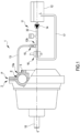
- the improved rotating combustion machine of the invention typically a four-stroke, spark-ignition engine, operating according to an Otto cycle, is diagrammatically shown in figure 1 , where it is indicated by reference numeral 1 as a whole.
- such a rotating combustion machine 1 comprises, according to the technical teachings suggested by Italian Patent no 1378900 here fully quoted again for reference:
- the improved rotating combustion machine 1 comprises an injection circuit, indicated as a whole by reference numeral 11, cooperating with the stator 2 to convey a pressurized cooling fluid L (typically water) in nebulized or sprayed form into the expansion sector E of the inner combustion chamber 3, the cooling fluid being contained in a service tank 12 belonging to the injection circuit 11, once the operating fluid has been combusted by the ignition means 8 and during the rotation of the mechanical transmission means 9 and of the rotors 7a, 7b about the linear axis Y.
- a pressurized cooling fluid L typically water
- the injection circuit 11 comprises a main delivery pipe 13 connected to the upper part P of the expansion sector E of the internal combustion chamber 3 defined within the stator 2.
- the injection circuit 11 appropriately further comprises pumping means, such as at least a volumetric pump 14, adapted to draw the cooling fluid L from the service tank 12 and introduce it under pressure into the expansion sector E of the internal combustion chamber 3.
- pumping means such as at least a volumetric pump 14, adapted to draw the cooling fluid L from the service tank 12 and introduce it under pressure into the expansion sector E of the internal combustion chamber 3.
- the injection circuit 11 includes a spray nozzle, not shown in the accompanying figures, facing the expansion sector E of the internal combustion chamber 3 and adapted to nebulize or spray the cooling fluid L.
- the aforesaid spray nozzle is arranged at the first end 13a of the main delivery pipe 13, the one directly facing (and communicating with, or facing) the expansion sector E of the internal combustion chamber 3.
- the injection circuit 11 further comprises a non-return valve 15 arranged downstream of the volumetric pump 14 and upstream of the first end 13a of the main delivery pipe 13.
- the non-return valve 15 is arranged at a second end 13b of the main flow pipe 13, opposite to the first end 13a defined above.
- the injection circuit 11 of the cooling fluid L further comprises a compensator 16 arranged downstream of the volumetric pump 14, in line with this in the initial duct 32 of the injection circuit 11.
- the injection circuit 11 further comprises an auxiliary return pipe 17 provided with valve means, such as a solenoid valve, which normally take an open position when the cooling fluid L is introduced under pressure into the expansion sector E of the inner combustion chamber 3 of the volumetric pump 14 and a closed position when the cooling fluid L must remain in the service tank 12 for any reason.
- valve means such as a solenoid valve
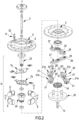
- the mechanical transmission means 9 are of the type indicated in the Italian Patent no. 1378900 , comprising:
- the transverse levers 25, 26 develop in a transverse direction to the linear axis of rotation defined by the primary shaft 10 of the mechanical transmission means 9 and are arranged axially close to each other on planes which are mutually distinct but parallel, thus defining longitudinal directions of development which are mutually offset according to a cross-like configuration.
- Figure 2 shows that, preferably, the eccentric means 29 project longitudinally and orthogonally from a side face 21a of each of the satellite toothed wheels 21 on the primitive diameter of which they are positioned, at a point different from the center of the satellite toothed wheels 21; this design concept gives rise to the eccentricity with which the interconnection hubs 23, 24 are connected to the satellite toothed wheels 21.
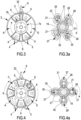
- the eccentric means 29 comprise, preferably but not exclusively, two projecting pins 30, 31 engaged in their respective slotted radial cams 27, 28 within which the projecting pins 30, 31 themselves slide during the rotation of the interconnecting hubs 23, 24 and the rotors 7a, 7b about the linear axis Y, as can be seen from the combined arrangement of figures 3a, 4a and 5a .
- the sliding of the orbiting pistons 6 in the inner combustion chamber 3 takes place simultaneously to the rotation of the rotors 7a, 7b, of the supporting planetary rotor 20 and the interconnection hubs 23, 24 about the linear axis Y and the rotation of the satellite toothed wheels 21 about the fixed solar toothed wheel 19 and the sliding of the eccentric means 29 in the slotted radial cams 27, 28.
- the ignition means 8 preferably comprise a spark plug 22 of the traditional type, clearly visible in figures 2 , 3 , 4 and 5 .
- the mechanical transmission means may comprise a number of interconnecting hubs and transverse connecting levers different from the one described above and shown in the appended figures; such a number varies according to the number of rotors provided in the rotating combustion engine of the current invention.
Landscapes
- Engineering & Computer Science (AREA)
- Mechanical Engineering (AREA)
- General Engineering & Computer Science (AREA)
- Chemical & Material Sciences (AREA)
- Combustion & Propulsion (AREA)
- Reciprocating Pumps (AREA)
- Air Bags (AREA)
- Noodles (AREA)
- Ignition Installations For Internal Combustion Engines (AREA)
Claims (13)
- Eine rotierende Verbrennungsmaschine (1), die Folgendes umfasst:- einen Stator (2), in dem eine innere Verbrennungskammer (3) definiert ist, die ein ringförmiges oder im Wesentlichen ringförmiges Profil hat und mindestens eine Ansaugöffnung (4) zum Einführen eines Betriebsfluids in die innere Kammer (3) und mindestens eine Auslassöffnung (5) zum Auslassen des Betriebsfluids aus der inneren Kammer (3) aufweist;- eine Vielzahl von umlaufenden Kolben (6), die mit einem oder mehreren Rotoren (7a, 7b) koaxial zu der inneren Kammer (3) verbunden sind und in der inneren Kammer (3) in der Weise gleitend in Drehung versetzt werden, dass ein variables Paar benachbarter umlaufender Kolben (6) die innere Kammer (3) dynamisch und nacheinander in einen Ansaugsektor (A) des Betriebsfluids, einen Kompressionssektor (C) des Betriebsfluids, einen Expansionssektor (E) der verbrannten Gase und einen Auslasssektor (S) der verbrannten Gase unterteilt;- Zündungsmittel (8) für die Verbrennung der Betriebsfluid, die zwischen dem Kompressionssektor (C) und dem Expansionssektor (E) der inneren Verbrennungskammer (3) angeordnet sind;- mechanische Übertragungsmittel (9), die mit den Rotoren (7a, 7b) und mit einer Hauptwelle (10) verbunden sind, auf die sie die Bewegung übertragen, und die geeignet sind, durch das Betriebsfluid in Drehung um eine lineare Achse (Y) versetzt zu werden, so dass die umlaufenden Kolben (6) in der inneren Kammer (3) in Drehung gleiten, einer nach dem anderen, gleichzeitig mit der Drehung der mechanischen Übertragungsmittel (9) und der Rotoren (7a, 7b) um die lineare Achse (Y),dadurch gekennzeichnet, dass sie eine Einspritzschaltung (11) umfasst, die mit dem Stator (2) derart zusammenwirkt, dass in den Expansionssektor (E) der inneren Verbrennungskammer (3) ein Kühlfluid (L) in zerstäubter oder pulverförmiger Form befördert wird, das in einem zur Einspritzschaltung (11) gehörenden Servicebehalter (12) enthalten ist, sobald die Verbrennung des Betriebsfluids durch die Zündungsmittel (8) erfolgt und während der Drehung der mechanischen Übertragungsmittel (9) und der Rotoren (7a, 7b) um die lineare Achse (Y).
- Maschine (1) nach Anspruch 1), dadurch gekennzeichnet, dass die Einspritzschaltung (11) ein Hauptzuführungsrohr (13) umfasst, das mit dem oberen Teil (P) des Expansionssektors (E) der inneren Verbrennungskammer (3) verbunden ist.
- Maschine (1) nach Anspruch 1) oder 2), dadurch gekennzeichnet, dass die Einspritzschaltung (11) mindestens eine volumetrische Pumpe (14) umfasst, die geeignet ist, das Kühlfluid (L) aus dem Servicebehalter (12) anzusaugen und es unter Druck in den Expansionssektor (E) der inneren Verbrennungskammer (3) einzuspritzen.
- Maschine (1) nach einem der vorhergehenden Ansprüche, dadurch gekennzeichnet, dass die Einspritzschaltung (11) eine Sprühdüse umfasst, die dem Expansionssektor (E) der inneren Verbrennungskammer (3) zugewandt und geeignet ist, die Kühlfluid (L) zu zerstäuben oder zu versprühen.
- Maschine (1) nach Anspruch 4) in Abhängigkeit von Anspruch 2), dadurch gekennzeichnet, dass die Sprühdüse an einem ersten Ende (13a) des Hauptzufuhrungsrohres (13) angeordnet ist, das dem Expansionssektor (E) der inneren Verbrennungskammer (3) zugewandt ist.
- Maschine (1) nach Anspruch 3), dadurch gekennzeichnet, dass die Einspritzschaltung (11) ein Rückschlagventil (15) aufweist, das stromabwärts der volumetrischen Pumpe (14) angeordnet ist.
- Maschine (1) nach Anspruch 6), wenn Anspruch 3) von Anspruch 2) abhängt, dadurch gekennzeichnet, dass das Rückschlagventil (15) an einem zweiten Ende (13b) des Hauptzufuhrungsrohres (13) angeordnet ist, das einem ersten Ende (13a) gegenüberliegt, das dem Expansionssektor (E) der inneren Verbrennungskammer (3) zugewandt ist.
- Maschine (1) nach Anspruch 3), dadurch gekennzeichnet, dass die Einspritzschaltung (11) einen Kompensator (16) umfasst, der stromabwärts der volumetrischen Pumpe (14) angeordnet ist.
- Maschine (1) nach Anspruch 3), dadurch gekennzeichnet, dass die Einspritzschaltung (11) einen Hilfsrücklaufrohr (17) umfasst, der mit Ventilmitteln (18) versehen ist, die normalerweise eine offene Position einnehmen, wenn das Kühlfluid (L) unter Druck in den Expansionssektor (E) der inneren Verbrennungskammer (3) eingeleitet wird, und eine geschlossene Position, wenn das Kühlfluid (L) in dem Servicebehalter (12) verbleiben muss.
- Maschine (1) nach einem der vorhergehenden Ansprüche, dadurch gekennzeichnet, dass die mechanischen Übertragungsmittel (9) Folgendes umfassen:- mindestens ein festes Sonnenzahnrad (19), das mit dem Stator (2) fest verbunden ist und koaxial zur inneren Verbrennungskammer (3) liegt;- einen Planetenstützrotor (20), der vollständig mit der Hauptwelle (10) verbunden ist und sich koaxial mit dem Sonnenzahnrad (19) um die Linearachse (Y) drehen kann;- eine Vielzahl von Satellitenzahnrädern (21), die auf dem Planetenrotor (20) drehbar gelagert sind und von zwei mal zwei gegenüberliegenden und symmetrisch zu der linearen Achse (Y) angeordneten Teilen in das Sonnenzahnrad (19) eingreifen;- eine oder mehrere Verbindungsnaben (23, 24), die jeweils mit einem der Rotoren (7a, 7b) verbunden und koaxial zu diesem sind und mit einem oder mehreren Querverbindungshebeln (25, 26) gekoppelt sind, die koaxial zu den Rotoren (7a, 7b) sind und zwischen den Verbindungsnaben (23, 24) und den Satellitenzahnrädern (21) angeordnet sind, wobei jeder der Querhebel (25, 26) ein Paar geschlitzter Radialnocken (27, 28) aufweist, die geeignet sind, Exzentermittel (29) gleitend aufzunehmen, die die Verbindungsnaben (23, 24) mit den Satellitenzahnrädern (21) verbinden.
- Maschine (1) nach Anspruch 10), dadurch gekennzeichnet, dass die Exzentermittel (29) in Längsrichtung und orthogonal von einer Seitenfläche (21a) jedes der Satellitenzahnräder (21), auf deren primitivem Durchmesser sie positioniert sind, an einem von der Mitte der Satellitenzahnräder (21) verschiedenen Punkt vorstehen.
- Maschine (1) nach Anspruch 10) oder 11), dadurch gekennzeichnet, dass die Exzentermittel (29) ein Paar von vorstehenden Stiften (30, 31) umfassen, von denen jeder in einen entsprechenden der geschlitzten Radialnocken (27, 28) eingreift, in denen die vorstehenden Stifte (29, 30) während der Drehung der Verbindungsnaben (23, 24) und der Rotoren (7a, 7b) um die lineare Achse (Y) gleiten.
- Maschine (1) nach einem der Ansprüche 10) bis 12), dadurch gekennzeichnet, dass das Gleiten der umlaufenden Kolben (6) in der inneren Verbrennungskammer (3) gleichzeitig mit der Drehung der Rotoren (7a, 7b), des Planetenrotors (20) und der Verbindungsnaben (23, 24) um die lineare Achse (Y) und der Drehung der Satellitenzahnräder (21) um das feste Sonnenzahnrad (19) und dem Gleiten der Exzentermittel (29) in den geschlitzten Radialnocken (27, 28) erfolgt.
Applications Claiming Priority (2)
| Application Number | Priority Date | Filing Date | Title |
|---|---|---|---|
| IT102019000005532A IT201900005532A1 (it) | 2019-04-10 | 2019-04-10 | Macchina perfezionata rotativa a combustione |
| PCT/IB2020/053385 WO2020208567A1 (en) | 2019-04-10 | 2020-04-09 | Improved rotating combustion machine |
Publications (3)
| Publication Number | Publication Date |
|---|---|
| EP3953573A1 EP3953573A1 (de) | 2022-02-16 |
| EP3953573C0 EP3953573C0 (de) | 2023-06-07 |
| EP3953573B1 true EP3953573B1 (de) | 2023-06-07 |
Family
ID=67262911
Family Applications (1)
| Application Number | Title | Priority Date | Filing Date |
|---|---|---|---|
| EP20723929.4A Active EP3953573B1 (de) | 2019-04-10 | 2020-04-09 | Verbesserte rotierende verbrennungsmaschine |
Country Status (3)
| Country | Link |
|---|---|
| EP (1) | EP3953573B1 (de) |
| IT (1) | IT201900005532A1 (de) |
| WO (1) | WO2020208567A1 (de) |
Family Cites Families (19)
| Publication number | Priority date | Publication date | Assignee | Title |
|---|---|---|---|---|
| GB191128828A (en) * | 1910-12-21 | 1912-06-27 | Voelund As | Improvements in Explosion Engines with Water Injection. |
| US1329625A (en) * | 1919-05-29 | 1920-02-03 | Stuart L Noble | Internal-combustion rotary engine |
| US1729242A (en) * | 1923-03-30 | 1929-09-24 | Bregere Louis Joseph | Valveless internal-combustion engine |
| US1644564A (en) * | 1923-06-02 | 1927-10-04 | Bullington Motors | Sealing means for rotary engines |
| US1676211A (en) * | 1923-06-02 | 1928-07-03 | Bullington Motors | Transmission for rotary engines |
| US1701534A (en) * | 1926-10-26 | 1929-02-12 | Knopp Rudolph | Rotary engine |
| US1778182A (en) * | 1927-01-03 | 1930-10-14 | Frank A Bullington | Annular-cylinder combustion engine |
| GB347803A (en) * | 1930-02-28 | 1931-05-07 | John William George | Motor power plant using combustion products and steam |
| GB1155429A (en) * | 1966-11-15 | 1969-06-18 | George Romney Stewart | Rotary Piston Internal Combustion Engine |
| US3990405A (en) * | 1975-01-16 | 1976-11-09 | Joseph Kecik | Rotary internal combustion engine |
| JPH0759888B2 (ja) * | 1984-03-02 | 1995-06-28 | 京セラ株式会社 | 水噴射式断熱セラミツクデイ−ゼルエンジン |
| IT1263709B (it) | 1993-11-10 | 1996-08-27 | Antonio Cadore | Macchina motrice/operatrice rotativa |
| US5832880A (en) * | 1997-07-28 | 1998-11-10 | Southwest Research Institute | Apparatus and method for controlling homogeneous charge compression ignition combustion in diesel engines |
| DE102007008565A1 (de) * | 2007-02-21 | 2008-08-28 | Klaus Schwarz | Verbrennungs- / Dampfmotor |
| UA87229C2 (ru) * | 2007-12-04 | 2009-06-25 | Евгений Федорович Драчко | Роторно-поршневая машина объемного расширения |
| IT1394033B1 (it) * | 2009-05-15 | 2012-05-25 | Ponti Motors S R L | Metodo per l'alimentazione di un motore a scoppio |
| CN102434271B (zh) * | 2011-08-18 | 2013-07-10 | 刘钢 | 二冲程往复活塞式燃汽发动机 |
| US9194287B1 (en) * | 2014-11-26 | 2015-11-24 | Bernard Bon | Double cam axial engine with over-expansion, variable compression, constant volume combustion, rotary valves and water injection for regenerative cooling |
| JP6369409B2 (ja) * | 2015-07-22 | 2018-08-08 | マツダ株式会社 | エンジンの制御装置 |
-
2019
- 2019-04-10 IT IT102019000005532A patent/IT201900005532A1/it unknown
-
2020
- 2020-04-09 WO PCT/IB2020/053385 patent/WO2020208567A1/en not_active Ceased
- 2020-04-09 EP EP20723929.4A patent/EP3953573B1/de active Active
Also Published As
| Publication number | Publication date |
|---|---|
| EP3953573C0 (de) | 2023-06-07 |
| EP3953573A1 (de) | 2022-02-16 |
| WO2020208567A1 (en) | 2020-10-15 |
| IT201900005532A1 (it) | 2020-10-10 |
Similar Documents
| Publication | Publication Date | Title |
|---|---|---|
| US11187146B2 (en) | Compound engine system with rotary engine | |
| US7000402B2 (en) | Compound gas turbine engines and methods of operation thereof | |
| EP2653694B1 (de) | Drehmotor und rotoreinheit dafür | |
| US10557407B2 (en) | Rotary internal combustion engine with pilot subchamber | |
| US20130081591A1 (en) | Rotary internal combustion engine | |
| US9896990B2 (en) | Internal combustion engine with port communication | |
| US11306651B2 (en) | Method of operating an internal combustion engine | |
| US9441538B2 (en) | Engine usable as a power source or pump | |
| EP3953573B1 (de) | Verbesserte rotierende verbrennungsmaschine | |
| US7621254B2 (en) | Internal combustion engine with toroidal cylinders | |
| CN104903544A (zh) | 循环式活塞发动机 | |
| CN113167172A (zh) | 转子型内燃机及其工作方法 | |
| US20130118445A1 (en) | Rotary piston engine | |
| CA2991582C (en) | Method of operating a rotary engine | |
| RU2119071C1 (ru) | Двигатель внутреннего сгорания четырехкратный, поршневой, кривошипно-кулисный, роторный с факельным самозажиганием (двскф), способ запуска двскф пиротехнический | |
| CN107165720B (zh) | 星形两冲程多缸发动机 | |
| RU2503833C1 (ru) | Би-ротативный двигатель внутреннего сгорания с воздушным охлаждением | |
| AU2015246708A2 (en) | Reciprocating engine | |
| JPH04101022A (ja) | 油圧源装置 | |
| WO2007107974A1 (en) | Crankshaftless internal combustion engine | |
| HK1206089B (en) | Oscillating piston engine with polygonal piston | |
| JPH08135461A (ja) | 対向気筒回転エンジン | |
| OA17507A (en) | An engine usable as a power source or pump. |
Legal Events
| Date | Code | Title | Description |
|---|---|---|---|
| STAA | Information on the status of an ep patent application or granted ep patent |
Free format text: STATUS: UNKNOWN |
|
| STAA | Information on the status of an ep patent application or granted ep patent |
Free format text: STATUS: THE INTERNATIONAL PUBLICATION HAS BEEN MADE |
|
| PUAI | Public reference made under article 153(3) epc to a published international application that has entered the european phase |
Free format text: ORIGINAL CODE: 0009012 |
|
| STAA | Information on the status of an ep patent application or granted ep patent |
Free format text: STATUS: REQUEST FOR EXAMINATION WAS MADE |
|
| 17P | Request for examination filed |
Effective date: 20211110 |
|
| AK | Designated contracting states |
Kind code of ref document: A1 Designated state(s): AL AT BE BG CH CY CZ DE DK EE ES FI FR GB GR HR HU IE IS IT LI LT LU LV MC MK MT NL NO PL PT RO RS SE SI SK SM TR |
|
| DAV | Request for validation of the european patent (deleted) | ||
| DAX | Request for extension of the european patent (deleted) | ||
| REG | Reference to a national code |
Ref country code: DE Ref legal event code: R079 Ref document number: 602020012087 Country of ref document: DE Free format text: PREVIOUS MAIN CLASS: F02B0047020000 Ipc: F01C0001077000 |
|
| RIC1 | Information provided on ipc code assigned before grant |
Ipc: F02B 53/00 20060101ALI20220922BHEP Ipc: F02B 47/02 20060101ALI20220922BHEP Ipc: F01C 21/06 20060101ALI20220922BHEP Ipc: F01C 1/077 20060101AFI20220922BHEP |
|
| GRAP | Despatch of communication of intention to grant a patent |
Free format text: ORIGINAL CODE: EPIDOSNIGR1 |
|
| STAA | Information on the status of an ep patent application or granted ep patent |
Free format text: STATUS: GRANT OF PATENT IS INTENDED |
|
| INTG | Intention to grant announced |
Effective date: 20221215 |
|
| GRAS | Grant fee paid |
Free format text: ORIGINAL CODE: EPIDOSNIGR3 |
|
| GRAA | (expected) grant |
Free format text: ORIGINAL CODE: 0009210 |
|
| STAA | Information on the status of an ep patent application or granted ep patent |
Free format text: STATUS: THE PATENT HAS BEEN GRANTED |
|
| AK | Designated contracting states |
Kind code of ref document: B1 Designated state(s): AL AT BE BG CH CY CZ DE DK EE ES FI FR GB GR HR HU IE IS IT LI LT LU LV MC MK MT NL NO PL PT RO RS SE SI SK SM TR |
|
| REG | Reference to a national code |
Ref country code: GB Ref legal event code: FG4D |
|
| REG | Reference to a national code |
Ref country code: CH Ref legal event code: EP Ref country code: AT Ref legal event code: REF Ref document number: 1575687 Country of ref document: AT Kind code of ref document: T Effective date: 20230615 |
|
| REG | Reference to a national code |
Ref country code: DE Ref legal event code: R096 Ref document number: 602020012087 Country of ref document: DE |
|
| U01 | Request for unitary effect filed |
Effective date: 20230706 |
|
| U07 | Unitary effect registered |
Designated state(s): AT BE BG DE DK EE FI FR IT LT LU LV MT NL PT SE SI Effective date: 20230718 |
|
| REG | Reference to a national code |
Ref country code: LT Ref legal event code: MG9D |
|
| PG25 | Lapsed in a contracting state [announced via postgrant information from national office to epo] |
Ref country code: NO Free format text: LAPSE BECAUSE OF FAILURE TO SUBMIT A TRANSLATION OF THE DESCRIPTION OR TO PAY THE FEE WITHIN THE PRESCRIBED TIME-LIMIT Effective date: 20230907 Ref country code: ES Free format text: LAPSE BECAUSE OF FAILURE TO SUBMIT A TRANSLATION OF THE DESCRIPTION OR TO PAY THE FEE WITHIN THE PRESCRIBED TIME-LIMIT Effective date: 20230607 |
|
| PG25 | Lapsed in a contracting state [announced via postgrant information from national office to epo] |
Ref country code: RS Free format text: LAPSE BECAUSE OF FAILURE TO SUBMIT A TRANSLATION OF THE DESCRIPTION OR TO PAY THE FEE WITHIN THE PRESCRIBED TIME-LIMIT Effective date: 20230607 Ref country code: HR Free format text: LAPSE BECAUSE OF FAILURE TO SUBMIT A TRANSLATION OF THE DESCRIPTION OR TO PAY THE FEE WITHIN THE PRESCRIBED TIME-LIMIT Effective date: 20230607 Ref country code: GR Free format text: LAPSE BECAUSE OF FAILURE TO SUBMIT A TRANSLATION OF THE DESCRIPTION OR TO PAY THE FEE WITHIN THE PRESCRIBED TIME-LIMIT Effective date: 20230908 |
|
| PG25 | Lapsed in a contracting state [announced via postgrant information from national office to epo] |
Ref country code: SK Free format text: LAPSE BECAUSE OF FAILURE TO SUBMIT A TRANSLATION OF THE DESCRIPTION OR TO PAY THE FEE WITHIN THE PRESCRIBED TIME-LIMIT Effective date: 20230607 |
|
| PG25 | Lapsed in a contracting state [announced via postgrant information from national office to epo] |
Ref country code: IS Free format text: LAPSE BECAUSE OF FAILURE TO SUBMIT A TRANSLATION OF THE DESCRIPTION OR TO PAY THE FEE WITHIN THE PRESCRIBED TIME-LIMIT Effective date: 20231007 |
|
| PG25 | Lapsed in a contracting state [announced via postgrant information from national office to epo] |
Ref country code: SM Free format text: LAPSE BECAUSE OF FAILURE TO SUBMIT A TRANSLATION OF THE DESCRIPTION OR TO PAY THE FEE WITHIN THE PRESCRIBED TIME-LIMIT Effective date: 20230607 Ref country code: SK Free format text: LAPSE BECAUSE OF FAILURE TO SUBMIT A TRANSLATION OF THE DESCRIPTION OR TO PAY THE FEE WITHIN THE PRESCRIBED TIME-LIMIT Effective date: 20230607 Ref country code: RO Free format text: LAPSE BECAUSE OF FAILURE TO SUBMIT A TRANSLATION OF THE DESCRIPTION OR TO PAY THE FEE WITHIN THE PRESCRIBED TIME-LIMIT Effective date: 20230607 Ref country code: IS Free format text: LAPSE BECAUSE OF FAILURE TO SUBMIT A TRANSLATION OF THE DESCRIPTION OR TO PAY THE FEE WITHIN THE PRESCRIBED TIME-LIMIT Effective date: 20231007 Ref country code: CZ Free format text: LAPSE BECAUSE OF FAILURE TO SUBMIT A TRANSLATION OF THE DESCRIPTION OR TO PAY THE FEE WITHIN THE PRESCRIBED TIME-LIMIT Effective date: 20230607 |
|
| PG25 | Lapsed in a contracting state [announced via postgrant information from national office to epo] |
Ref country code: PL Free format text: LAPSE BECAUSE OF FAILURE TO SUBMIT A TRANSLATION OF THE DESCRIPTION OR TO PAY THE FEE WITHIN THE PRESCRIBED TIME-LIMIT Effective date: 20230607 |
|
| REG | Reference to a national code |
Ref country code: DE Ref legal event code: R097 Ref document number: 602020012087 Country of ref document: DE |
|
| PLBE | No opposition filed within time limit |
Free format text: ORIGINAL CODE: 0009261 |
|
| STAA | Information on the status of an ep patent application or granted ep patent |
Free format text: STATUS: NO OPPOSITION FILED WITHIN TIME LIMIT |
|
| U20 | Renewal fee for the european patent with unitary effect paid |
Year of fee payment: 5 Effective date: 20240320 |
|
| 26N | No opposition filed |
Effective date: 20240308 |
|
| PG25 | Lapsed in a contracting state [announced via postgrant information from national office to epo] |
Ref country code: MC Free format text: LAPSE BECAUSE OF FAILURE TO SUBMIT A TRANSLATION OF THE DESCRIPTION OR TO PAY THE FEE WITHIN THE PRESCRIBED TIME-LIMIT Effective date: 20230607 |
|
| PG25 | Lapsed in a contracting state [announced via postgrant information from national office to epo] |
Ref country code: MC Free format text: LAPSE BECAUSE OF FAILURE TO SUBMIT A TRANSLATION OF THE DESCRIPTION OR TO PAY THE FEE WITHIN THE PRESCRIBED TIME-LIMIT Effective date: 20230607 |
|
| REG | Reference to a national code |
Ref country code: CH Ref legal event code: PL |
|
| GBPC | Gb: european patent ceased through non-payment of renewal fee |
Effective date: 20240409 |
|
| PG25 | Lapsed in a contracting state [announced via postgrant information from national office to epo] |
Ref country code: GB Free format text: LAPSE BECAUSE OF NON-PAYMENT OF DUE FEES Effective date: 20240409 |
|
| PG25 | Lapsed in a contracting state [announced via postgrant information from national office to epo] |
Ref country code: GB Free format text: LAPSE BECAUSE OF NON-PAYMENT OF DUE FEES Effective date: 20240409 Ref country code: CH Free format text: LAPSE BECAUSE OF NON-PAYMENT OF DUE FEES Effective date: 20240430 |
|
| PG25 | Lapsed in a contracting state [announced via postgrant information from national office to epo] |
Ref country code: IE Free format text: LAPSE BECAUSE OF NON-PAYMENT OF DUE FEES Effective date: 20240409 |
|
| U20 | Renewal fee for the european patent with unitary effect paid |
Year of fee payment: 6 Effective date: 20250320 |
|
| PG25 | Lapsed in a contracting state [announced via postgrant information from national office to epo] |
Ref country code: CY Free format text: LAPSE BECAUSE OF FAILURE TO SUBMIT A TRANSLATION OF THE DESCRIPTION OR TO PAY THE FEE WITHIN THE PRESCRIBED TIME-LIMIT; INVALID AB INITIO Effective date: 20200409 |
|
| PG25 | Lapsed in a contracting state [announced via postgrant information from national office to epo] |
Ref country code: HU Free format text: LAPSE BECAUSE OF FAILURE TO SUBMIT A TRANSLATION OF THE DESCRIPTION OR TO PAY THE FEE WITHIN THE PRESCRIBED TIME-LIMIT; INVALID AB INITIO Effective date: 20200409 |
|
| U20 | Renewal fee for the european patent with unitary effect paid |
Year of fee payment: 7 Effective date: 20260310 |