EP3951282A1 - Traitement actif de l'air d'évacuation d'une pompe à chaleur - Google Patents
Traitement actif de l'air d'évacuation d'une pompe à chaleur Download PDFInfo
- Publication number
- EP3951282A1 EP3951282A1 EP21187653.7A EP21187653A EP3951282A1 EP 3951282 A1 EP3951282 A1 EP 3951282A1 EP 21187653 A EP21187653 A EP 21187653A EP 3951282 A1 EP3951282 A1 EP 3951282A1
- Authority
- EP
- European Patent Office
- Prior art keywords
- heat pump
- working fluid
- pump according
- exhaust gas
- air duct
- Prior art date
- Legal status (The legal status is an assumption and is not a legal conclusion. Google has not performed a legal analysis and makes no representation as to the accuracy of the status listed.)
- Granted
Links
- 238000004887 air purification Methods 0.000 title 1
- 239000002699 waste material Substances 0.000 title 1
- 239000012530 fluid Substances 0.000 claims abstract description 44
- 230000003647 oxidation Effects 0.000 claims abstract description 33
- 238000007254 oxidation reaction Methods 0.000 claims abstract description 33
- 239000002775 capsule Substances 0.000 claims abstract description 29
- 238000009434 installation Methods 0.000 claims abstract description 6
- 239000003054 catalyst Substances 0.000 claims description 13
- 239000000919 ceramic Substances 0.000 claims description 5
- 230000003197 catalytic effect Effects 0.000 claims description 4
- 230000002000 scavenging effect Effects 0.000 claims description 4
- 238000009423 ventilation Methods 0.000 claims description 4
- 229910002367 SrTiO Inorganic materials 0.000 claims description 3
- 125000000896 monocarboxylic acid group Chemical group 0.000 claims description 3
- 230000001105 regulatory effect Effects 0.000 claims description 3
- 230000001678 irradiating effect Effects 0.000 claims 1
- 238000005259 measurement Methods 0.000 claims 1
- 230000005855 radiation Effects 0.000 claims 1
- 230000001960 triggered effect Effects 0.000 claims 1
- 239000003570 air Substances 0.000 description 46
- 239000007789 gas Substances 0.000 description 27
- ATUOYWHBWRKTHZ-UHFFFAOYSA-N Propane Chemical compound CCC ATUOYWHBWRKTHZ-UHFFFAOYSA-N 0.000 description 8
- 238000010438 heat treatment Methods 0.000 description 7
- XLYOFNOQVPJJNP-UHFFFAOYSA-N water Substances O XLYOFNOQVPJJNP-UHFFFAOYSA-N 0.000 description 7
- 239000000203 mixture Substances 0.000 description 6
- 239000003507 refrigerant Substances 0.000 description 6
- 239000012267 brine Substances 0.000 description 5
- 238000000034 method Methods 0.000 description 5
- HPALAKNZSZLMCH-UHFFFAOYSA-M sodium;chloride;hydrate Chemical compound O.[Na+].[Cl-] HPALAKNZSZLMCH-UHFFFAOYSA-M 0.000 description 5
- 239000001294 propane Substances 0.000 description 4
- 231100001261 hazardous Toxicity 0.000 description 3
- 238000005057 refrigeration Methods 0.000 description 3
- 231100000331 toxic Toxicity 0.000 description 3
- 230000002588 toxic effect Effects 0.000 description 3
- QGZKDVFQNNGYKY-UHFFFAOYSA-N Ammonia Chemical compound N QGZKDVFQNNGYKY-UHFFFAOYSA-N 0.000 description 2
- QQONPFPTGQHPMA-UHFFFAOYSA-N Propene Chemical compound CC=C QQONPFPTGQHPMA-UHFFFAOYSA-N 0.000 description 2
- 238000004378 air conditioning Methods 0.000 description 2
- QVGXLLKOCUKJST-UHFFFAOYSA-N atomic oxygen Chemical compound [O] QVGXLLKOCUKJST-UHFFFAOYSA-N 0.000 description 2
- 238000006243 chemical reaction Methods 0.000 description 2
- 238000002485 combustion reaction Methods 0.000 description 2
- 238000006356 dehydrogenation reaction Methods 0.000 description 2
- 238000010790 dilution Methods 0.000 description 2
- 239000012895 dilution Substances 0.000 description 2
- 239000003651 drinking water Substances 0.000 description 2
- 235000020188 drinking water Nutrition 0.000 description 2
- 238000004880 explosion Methods 0.000 description 2
- 239000002360 explosive Substances 0.000 description 2
- 238000000605 extraction Methods 0.000 description 2
- 239000001301 oxygen Substances 0.000 description 2
- 229910052760 oxygen Inorganic materials 0.000 description 2
- XZPVPNZTYPUODG-UHFFFAOYSA-M sodium;chloride;dihydrate Chemical compound O.O.[Na+].[Cl-] XZPVPNZTYPUODG-UHFFFAOYSA-M 0.000 description 2
- 239000007787 solid Substances 0.000 description 2
- RNFJDJUURJAICM-UHFFFAOYSA-N 2,2,4,4,6,6-hexaphenoxy-1,3,5-triaza-2$l^{5},4$l^{5},6$l^{5}-triphosphacyclohexa-1,3,5-triene Chemical compound N=1P(OC=2C=CC=CC=2)(OC=2C=CC=CC=2)=NP(OC=2C=CC=CC=2)(OC=2C=CC=CC=2)=NP=1(OC=1C=CC=CC=1)OC1=CC=CC=C1 RNFJDJUURJAICM-UHFFFAOYSA-N 0.000 description 1
- 241001136792 Alle Species 0.000 description 1
- 235000016936 Dendrocalamus strictus Nutrition 0.000 description 1
- LFQSCWFLJHTTHZ-UHFFFAOYSA-N Ethanol Chemical compound CCO LFQSCWFLJHTTHZ-UHFFFAOYSA-N 0.000 description 1
- 206010019233 Headaches Diseases 0.000 description 1
- 206010028813 Nausea Diseases 0.000 description 1
- CBENFWSGALASAD-UHFFFAOYSA-N Ozone Chemical compound [O-][O+]=O CBENFWSGALASAD-UHFFFAOYSA-N 0.000 description 1
- 238000010521 absorption reaction Methods 0.000 description 1
- 150000001298 alcohols Chemical class 0.000 description 1
- 239000012080 ambient air Substances 0.000 description 1
- 229910021529 ammonia Inorganic materials 0.000 description 1
- 239000011230 binding agent Substances 0.000 description 1
- 238000001816 cooling Methods 0.000 description 1
- 238000004200 deflagration Methods 0.000 description 1
- 238000001514 detection method Methods 0.000 description 1
- 230000000694 effects Effects 0.000 description 1
- 238000005485 electric heating Methods 0.000 description 1
- 238000005538 encapsulation Methods 0.000 description 1
- 239000003063 flame retardant Substances 0.000 description 1
- 231100000869 headache Toxicity 0.000 description 1
- 229930195733 hydrocarbon Natural products 0.000 description 1
- 150000002430 hydrocarbons Chemical class 0.000 description 1
- 230000001788 irregular Effects 0.000 description 1
- 230000007774 longterm Effects 0.000 description 1
- 230000003533 narcotic effect Effects 0.000 description 1
- 230000008693 nausea Effects 0.000 description 1
- 239000007800 oxidant agent Substances 0.000 description 1
- 230000001681 protective effect Effects 0.000 description 1
- 238000010791 quenching Methods 0.000 description 1
- 230000000171 quenching effect Effects 0.000 description 1
- 238000001179 sorption measurement Methods 0.000 description 1
- 230000007306 turnover Effects 0.000 description 1
- 238000010792 warming Methods 0.000 description 1
Images

Classifications
-
- F—MECHANICAL ENGINEERING; LIGHTING; HEATING; WEAPONS; BLASTING
- F24—HEATING; RANGES; VENTILATING
- F24H—FLUID HEATERS, e.g. WATER OR AIR HEATERS, HAVING HEAT-GENERATING MEANS, e.g. HEAT PUMPS, IN GENERAL
- F24H4/00—Fluid heaters characterised by the use of heat pumps
- F24H4/02—Water heaters
- F24H4/04—Storage heaters
-
- F—MECHANICAL ENGINEERING; LIGHTING; HEATING; WEAPONS; BLASTING
- F23—COMBUSTION APPARATUS; COMBUSTION PROCESSES
- F23D—BURNERS
- F23D14/00—Burners for combustion of a gas, e.g. of a gas stored under pressure as a liquid
- F23D14/46—Details, e.g. noise reduction means
- F23D14/72—Safety devices, e.g. operative in case of failure of gas supply
- F23D14/82—Preventing flashback or blowback
-
- F—MECHANICAL ENGINEERING; LIGHTING; HEATING; WEAPONS; BLASTING
- F23—COMBUSTION APPARATUS; COMBUSTION PROCESSES
- F23G—CREMATION FURNACES; CONSUMING WASTE PRODUCTS BY COMBUSTION
- F23G7/00—Incinerators or other apparatus for consuming industrial waste, e.g. chemicals
- F23G7/06—Incinerators or other apparatus for consuming industrial waste, e.g. chemicals of waste gases or noxious gases, e.g. exhaust gases
- F23G7/07—Incinerators or other apparatus for consuming industrial waste, e.g. chemicals of waste gases or noxious gases, e.g. exhaust gases in which combustion takes place in the presence of catalytic material
-
- F—MECHANICAL ENGINEERING; LIGHTING; HEATING; WEAPONS; BLASTING
- F23—COMBUSTION APPARATUS; COMBUSTION PROCESSES
- F23Q—IGNITION; EXTINGUISHING-DEVICES
- F23Q13/00—Igniters not otherwise provided for
- F23Q13/005—Igniters not otherwise provided for using light, e.g. sunlight or laser
-
- F—MECHANICAL ENGINEERING; LIGHTING; HEATING; WEAPONS; BLASTING
- F24—HEATING; RANGES; VENTILATING
- F24H—FLUID HEATERS, e.g. WATER OR AIR HEATERS, HAVING HEAT-GENERATING MEANS, e.g. HEAT PUMPS, IN GENERAL
- F24H15/00—Control of fluid heaters
- F24H15/10—Control of fluid heaters characterised by the purpose of the control
- F24H15/12—Preventing or detecting fluid leakage
-
- F—MECHANICAL ENGINEERING; LIGHTING; HEATING; WEAPONS; BLASTING
- F24—HEATING; RANGES; VENTILATING
- F24H—FLUID HEATERS, e.g. WATER OR AIR HEATERS, HAVING HEAT-GENERATING MEANS, e.g. HEAT PUMPS, IN GENERAL
- F24H9/00—Details
- F24H9/02—Casings; Cover lids; Ornamental panels
-
- F—MECHANICAL ENGINEERING; LIGHTING; HEATING; WEAPONS; BLASTING
- F24—HEATING; RANGES; VENTILATING
- F24H—FLUID HEATERS, e.g. WATER OR AIR HEATERS, HAVING HEAT-GENERATING MEANS, e.g. HEAT PUMPS, IN GENERAL
- F24H9/00—Details
- F24H9/20—Arrangement or mounting of control or safety devices
- F24H9/2007—Arrangement or mounting of control or safety devices for water heaters
- F24H9/2014—Arrangement or mounting of control or safety devices for water heaters using electrical energy supply
- F24H9/2021—Storage heaters
-
- F—MECHANICAL ENGINEERING; LIGHTING; HEATING; WEAPONS; BLASTING
- F25—REFRIGERATION OR COOLING; COMBINED HEATING AND REFRIGERATION SYSTEMS; HEAT PUMP SYSTEMS; MANUFACTURE OR STORAGE OF ICE; LIQUEFACTION SOLIDIFICATION OF GASES
- F25B—REFRIGERATION MACHINES, PLANTS OR SYSTEMS; COMBINED HEATING AND REFRIGERATION SYSTEMS; HEAT PUMP SYSTEMS
- F25B49/00—Arrangement or mounting of control or safety devices
- F25B49/005—Arrangement or mounting of control or safety devices of safety devices
-
- F—MECHANICAL ENGINEERING; LIGHTING; HEATING; WEAPONS; BLASTING
- F25—REFRIGERATION OR COOLING; COMBINED HEATING AND REFRIGERATION SYSTEMS; HEAT PUMP SYSTEMS; MANUFACTURE OR STORAGE OF ICE; LIQUEFACTION SOLIDIFICATION OF GASES
- F25B—REFRIGERATION MACHINES, PLANTS OR SYSTEMS; COMBINED HEATING AND REFRIGERATION SYSTEMS; HEAT PUMP SYSTEMS
- F25B13/00—Compression machines, plants or systems, with reversible cycle
-
- F—MECHANICAL ENGINEERING; LIGHTING; HEATING; WEAPONS; BLASTING
- F25—REFRIGERATION OR COOLING; COMBINED HEATING AND REFRIGERATION SYSTEMS; HEAT PUMP SYSTEMS; MANUFACTURE OR STORAGE OF ICE; LIQUEFACTION SOLIDIFICATION OF GASES
- F25B—REFRIGERATION MACHINES, PLANTS OR SYSTEMS; COMBINED HEATING AND REFRIGERATION SYSTEMS; HEAT PUMP SYSTEMS
- F25B25/00—Machines, plants or systems, using a combination of modes of operation covered by two or more of the groups F25B1/00 - F25B23/00
- F25B25/005—Machines, plants or systems, using a combination of modes of operation covered by two or more of the groups F25B1/00 - F25B23/00 using primary and secondary systems
-
- F—MECHANICAL ENGINEERING; LIGHTING; HEATING; WEAPONS; BLASTING
- F25—REFRIGERATION OR COOLING; COMBINED HEATING AND REFRIGERATION SYSTEMS; HEAT PUMP SYSTEMS; MANUFACTURE OR STORAGE OF ICE; LIQUEFACTION SOLIDIFICATION OF GASES
- F25B—REFRIGERATION MACHINES, PLANTS OR SYSTEMS; COMBINED HEATING AND REFRIGERATION SYSTEMS; HEAT PUMP SYSTEMS
- F25B2500/00—Problems to be solved
- F25B2500/22—Preventing, detecting or repairing leaks of refrigeration fluids
- F25B2500/222—Detecting refrigerant leaks
-
- F—MECHANICAL ENGINEERING; LIGHTING; HEATING; WEAPONS; BLASTING
- F25—REFRIGERATION OR COOLING; COMBINED HEATING AND REFRIGERATION SYSTEMS; HEAT PUMP SYSTEMS; MANUFACTURE OR STORAGE OF ICE; LIQUEFACTION SOLIDIFICATION OF GASES
- F25B—REFRIGERATION MACHINES, PLANTS OR SYSTEMS; COMBINED HEATING AND REFRIGERATION SYSTEMS; HEAT PUMP SYSTEMS
- F25B30/00—Heat pumps
- F25B30/02—Heat pumps of the compression type
-
- Y—GENERAL TAGGING OF NEW TECHNOLOGICAL DEVELOPMENTS; GENERAL TAGGING OF CROSS-SECTIONAL TECHNOLOGIES SPANNING OVER SEVERAL SECTIONS OF THE IPC; TECHNICAL SUBJECTS COVERED BY FORMER USPC CROSS-REFERENCE ART COLLECTIONS [XRACs] AND DIGESTS
- Y02—TECHNOLOGIES OR APPLICATIONS FOR MITIGATION OR ADAPTATION AGAINST CLIMATE CHANGE
- Y02A—TECHNOLOGIES FOR ADAPTATION TO CLIMATE CHANGE
- Y02A50/00—TECHNOLOGIES FOR ADAPTATION TO CLIMATE CHANGE in human health protection, e.g. against extreme weather
- Y02A50/20—Air quality improvement or preservation, e.g. vehicle emission control or emission reduction by using catalytic converters
Definitions
- the invention relates to irregular states in refrigeration circuits in which a dangerous working fluid acting as a refrigerant is circulated in a thermodynamic cycle, such as the Clausius-Rankine cycle.
- thermodynamic cycle such as the Clausius-Rankine cycle.
- These are mainly heat pumps, air conditioning systems and refrigerators, as they are common in residential buildings.
- the invention relates to a heat pump to be placed inside a dwelling and also to serve ventilation purposes.
- Residential buildings are private houses, apartment building complexes, hospitals, hotel complexes, restaurants and combined residential and commercial buildings in which people live and work permanently, in contrast to mobile devices such as car air conditioning systems or transport boxes, or industrial systems or medical devices. What these cycle processes have in common is that they generate useful heat or cold using energy and form heat transfer systems.
- thermodynamic cycle processes used have been known for a long time, as have the safety problems that can arise when using suitable working fluids. Apart from water, the most common working fluids of the time were flammable and toxic. In the last century they led to the development of safety refrigerants, which consisted of fluorinated hydrocarbons. However, it turned out that these safety refrigerants damage the ozone layer, lead to global warming, and that their safety-related harmlessness led to design carelessness. Up to 70% of the turnover was accounted for by the need to refill leaking systems and their leakage losses, which was accepted as long as this was felt to be economically justifiable in individual cases and promoted the need for replacement purchases.
- the problems encountered in the safety design of such systems are in the WO 2015/032905 A1 vividly described.
- the lower ignition limit of R290 as a working fluid is around 1.7 percent by volume in air, which corresponds to 38 g/m 3 in air. If the refrigeration process is carried out in a surrounding, hermetically sealed, but otherwise air-filled space with the working fluid R290, the problem of detecting a critical, explosive situation arises after a fault in which the working fluid into this hermetically sealed space.
- Electrical sensors for detecting critical concentrations are difficult to design in an explosion-proof manner, which is why the propane detection by the sensors themselves significantly increases the risk of explosion, with the exception of infrared sensors.
- R290 is also toxic. Inhalation of concentrations above approx. 2 g/m 3 causes narcotic effects, headaches and nausea. This concerns people who have to solve a recognized problem on site before there is a risk of explosion.
- the EP 3 106 780 B1 describes an absorption heat pump that includes a sorption stage.
- a blower sucks off the refrigerant released via a binding agent and feeds the residue downstream to a burner, which is designed as an electrically operated heating coil, a pilot flame or a catalytic burner.
- the object of the invention is therefore to provide a device and a method for safe and efficient exhaust air treatment for a heat pump that is set up in a residential building and in which a left-handed thermodynamic cycle process is carried out in a closed, hermetically sealed working fluid circulation using an inflammable working fluid .
- the supply air duct and the exhaust air duct can also consist of one piece.
- the supply air duct must be fitted with a non-return valve.
- the resulting overpressure causes the air mixture to escape from the capsule housing directly into the exhaust gas oxidation device, where it is rendered harmless.
- the concentration of the working fluid in the air in the capsule housing is low, but it can increase quickly depending on the size of the leak. It depends on whether and, if so, how much additional air has to be fed into the exhaust gas oxidation device.
- An embodiment of the invention therefore provides that a gas sensor is provided in the capsule housing, which switches on the conveying fan for exhaust air if gaseous working fluid is detected.
- An improved embodiment provides that the concentration of gaseous working fluid is measured in the capsule housing and the conveying fan for exhaust air is regulated according to the concentration of working fluid or within a setting range for excess oxygen (lambda window).
- nets with appropriate mesh sizes or porous ceramic bodies can also be used.
- the required gap width is that of the "quenching diameter" which corresponds to the unburned gas boundary layer along a cold wall surface.
- a conveying fan is provided, which is designed to be explosion-proof.
- the capsule housing must have an air inlet that is either integrated in the air duct or is designed as openings in the capsule housing through which air can flow in but not out, for example through louvre flaps that can only be opened in one direction.
- the combustion can also be regulated via a venturi, with the connection to the vacuum chamber of the heat pump housing representing the gas connection, so that this structure is operated with only one scavenging air fan.
- the media supply from the heat pump is then controlled via a variable aperture control, which is implemented with the gas sensor.
- a catalyst is used in the ignition chamber, this catalyst can also be a porous ceramic, which also acts as a flame retardant grid.
- oxidation or dehydrogenation takes place from 500 °C.
- This oxidation produces an alcohol.
- This alcohol is water soluble and at the low concentration is less of a problem than propane.
- Propene is formed during dehydrogenation. This can be better broken down due to the double bond.
- the exhaust gas oxidation can also take place in stages, in that first a catalytic conversion takes place at a lower temperature and only then a further total oxidation to CO 2 and water is carried out.
- an oxidation of propane at 150-180° C. can be carried out in a first stage using Co(III)-CF 3 COOH and/or Pt/SrTiO 3 as catalysts.
- total oxidation is then achieved at 150° C. using the Ru/CeO 2 catalyst.
- the ignition can be done using a glow plug, a piezo element or UV light.
- the ignition also depends on whether a catalyst is used, if a catalyst is used on a porous solid ceramic, the ignition can also take place by means of UV light directed at this solid.
- a UV laser can also be used for this purpose.
- either only the conveying fan to the ignition chamber from the capsule housing can be activated, which is to be done for smaller concentrations, or forced ventilation is also activated by means of the conveying fan at the foot of the air duct, which is to be done for larger concentrations of working fluid or rapid increases in concentration has to have a sufficient excess of air to guarantee.
- ignition in the ignition chamber can also be dispensed with, since the subsequent dilution with additional air means that an ignitable mixture cannot subsequently develop.
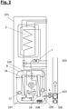
- the brine-water heat pump 101 has the hot water elements, such as the drinking water tank 2, the electric auxiliary heater 7 and the safety temperature limiter 6 and a cable routing duct 1 in the upper part.
- An electrical switch box 3 with a controller circuit board 4 and a connection for the power supply 5 are provided on the front.
- thermodynamic devices that carry the working fluid in the refrigeration circuit, these are the compressor 12, the expansion valve 14, the evaporator 18, the condenser 19 and the 3-way valve 8, plus the pumps for the heat transfer fluids, these are the heating circuit pump 9 and the brine pump 17, as well as the filling and drain valves for the heating circuit 10 and the brine circuit 16.
- thermodynamic devices show the changes due to the security concept.
- the part in which the thermodynamic devices are located is encapsulated by a capsule housing 107 .
- this encapsulation is sealed to the outside, but air can flow in from the outside via an air inlet opening 104 if a negative pressure arises.
- An air duct 103 which forms both the supply air duct and the exhaust air duct, leads from the capsule housing 107 into the installation space, with the air being guided from the capsule housing 107 via an extraction device 109, a conveying fan 105 and an ignition chamber 102 into the air duct 103.
- the escaping working fluid increases the pressure in the capsule housing and the working fluid-air mixture escapes through the extraction device 109 into the ignition chamber 102. If the mixture is ignitable, ignition occurs and the working fluid oxidizes, heating up. It rises in the air duct 103 due to the chimney effect.
- the air access is still closed by the conveying fan 106, the exhaust gas can only escape upwards into the installation room.
- the working fluid is detected in the gas sensor 108.
- the conveying fan 106 is also started to ensure that there is always excess air in the exhaust gas oxidizer.
- the gas sensor can determine the concentrations to regulate the conveying fans 105 and 106 to set an ideal excess air.
- the conveyance fan 106 can also be turned on to cool the ignition chamber by directing a constant flow of air around the outside of the ignition chamber.
- the two conveyor fans must be explosion-proof, and a battery-powered emergency power supply must be set up in the event of a power failure.
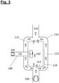
- FIG 3 shows an exemplary embodiment of an exhaust gas oxidation device 110.
- This is equipped with an ignition device 111, which generates ignition sparks at short intervals. If an ignitable mixture flows past the ignition device 111 from the capsule housing 107 via the suction connection 109 , ignition takes place in the ignition chamber 102 . A lot of heat can be generated during this combustion process, so in order to cool the ignition chamber 102, a flow area 112 is provided, the air flow for this is provided by the conveying fan 106.
- the flow area 112 is delimited on the inside of the ignition chamber 102 by one or more inlet grilles 113, one or more protective plates 114 and one or more outlet grilles.
- the openings in the grilles are dimensioned in accordance with international standards for flame arresters.
- the flow control is in 3 shown by arrows.
- a chimney pipe serves as the exhaust gas outlet.
Landscapes
- Engineering & Computer Science (AREA)
- Mechanical Engineering (AREA)
- General Engineering & Computer Science (AREA)
- Chemical & Material Sciences (AREA)
- Combustion & Propulsion (AREA)
- Physics & Mathematics (AREA)
- Thermal Sciences (AREA)
- Environmental & Geological Engineering (AREA)
- Chemical Kinetics & Catalysis (AREA)
- Optics & Photonics (AREA)
- Air Conditioning Control Device (AREA)
- Ventilation (AREA)
- Heat-Exchange Devices With Radiators And Conduit Assemblies (AREA)
Applications Claiming Priority (1)
| Application Number | Priority Date | Filing Date | Title |
|---|---|---|---|
| DE102020120615.1A DE102020120615A1 (de) | 2020-08-05 | 2020-08-05 | Aktive Abluftbehandlung für eine Wärmepumpe |
Publications (2)
| Publication Number | Publication Date |
|---|---|
| EP3951282A1 true EP3951282A1 (fr) | 2022-02-09 |
| EP3951282B1 EP3951282B1 (fr) | 2024-08-07 |
Family
ID=77050898
Family Applications (1)
| Application Number | Title | Priority Date | Filing Date |
|---|---|---|---|
| EP21187653.7A Active EP3951282B1 (fr) | 2020-08-05 | 2021-07-26 | Traitement actif de l'air d'évacuation d'une pompe à chaleur |
Country Status (2)
| Country | Link |
|---|---|
| EP (1) | EP3951282B1 (fr) |
| DE (1) | DE102020120615A1 (fr) |
Families Citing this family (2)
| Publication number | Priority date | Publication date | Assignee | Title |
|---|---|---|---|---|
| US20220212698A1 (en) * | 2019-08-27 | 2022-07-07 | Faiveley Transport Leipzig Gmbh & Co. Kg | Climate control system for a vehicle |
| DE102021213213A1 (de) | 2021-11-24 | 2023-05-25 | Robert Bosch Gesellschaft mit beschränkter Haftung | Wärmepumpenmodul mit Explosionsschutzvorrichtung |
Citations (5)
| Publication number | Priority date | Publication date | Assignee | Title |
|---|---|---|---|---|
| WO2003010473A1 (fr) * | 2001-07-26 | 2003-02-06 | Climastar Sa | Pompe a chaleur dispositif de ventilation de securite |
| WO2015032905A1 (fr) | 2013-09-05 | 2015-03-12 | Holger König | Procédé permettant d'empêcher une fuite d'un contenant et contenant pourvu d'un dispositif anti-fuite |
| EP3106780A1 (fr) * | 2015-06-17 | 2016-12-21 | Vaillant GmbH | Installation de pompes a chaleur |
| US20190128565A1 (en) * | 2017-10-30 | 2019-05-02 | Rheem Manufacturing Company | Hybrid water heater |
| DE102018109646A1 (de) * | 2018-04-23 | 2019-10-24 | Vaillant Gmbh | Fluidsorption |
-
2020
- 2020-08-05 DE DE102020120615.1A patent/DE102020120615A1/de active Pending
-
2021
- 2021-07-26 EP EP21187653.7A patent/EP3951282B1/fr active Active
Patent Citations (6)
| Publication number | Priority date | Publication date | Assignee | Title |
|---|---|---|---|---|
| WO2003010473A1 (fr) * | 2001-07-26 | 2003-02-06 | Climastar Sa | Pompe a chaleur dispositif de ventilation de securite |
| WO2015032905A1 (fr) | 2013-09-05 | 2015-03-12 | Holger König | Procédé permettant d'empêcher une fuite d'un contenant et contenant pourvu d'un dispositif anti-fuite |
| EP3106780A1 (fr) * | 2015-06-17 | 2016-12-21 | Vaillant GmbH | Installation de pompes a chaleur |
| EP3106780B1 (fr) | 2015-06-17 | 2017-11-22 | Vaillant GmbH | Installation de pompes à chaleur |
| US20190128565A1 (en) * | 2017-10-30 | 2019-05-02 | Rheem Manufacturing Company | Hybrid water heater |
| DE102018109646A1 (de) * | 2018-04-23 | 2019-10-24 | Vaillant Gmbh | Fluidsorption |
Non-Patent Citations (2)
| Title |
|---|
| "System geoTHERM", March 2009, VAILLANT GMBH |
| "versoTherm plus", August 2018, VAILLANT GMBH |
Also Published As
| Publication number | Publication date |
|---|---|
| DE102020120615A1 (de) | 2022-02-10 |
| EP3951282B1 (fr) | 2024-08-07 |
Similar Documents
| Publication | Publication Date | Title |
|---|---|---|
| EP3486582B1 (fr) | Dispositif de détection des fuites au moyen de capacité adsorbante | |
| EP3951282B1 (fr) | Traitement actif de l'air d'évacuation d'une pompe à chaleur | |
| DE69926291T2 (de) | Klimaanlage | |
| EP3792572A1 (fr) | Dispositif de rinçage de sécurité pour une pompe à chaleur | |
| EP3578895B1 (fr) | Dispositif et procédé pour le rinçage sûr et économique d'une enceinte | |
| DE202017107917U1 (de) | Kältemittel-Leckagedetektion durch Verwendung eines Fluidadditivs | |
| DE202016103305U1 (de) | Explosionsgeschützte Vorrichtung zum Temperieren von Wärmeträgerfluiden | |
| EP3940314B1 (fr) | Dispositif de rinçage de sécurité pour une pompe à chaleur | |
| EP3581861A2 (fr) | Sorption du fluide | |
| EP3486583B1 (fr) | Circuit froid à sécurité anti-fuite | |
| EP3748257A1 (fr) | Dispositif pour la performance sûre d'un procédé circulaire thermodynamique à rotation à gauche au moyen d'un fluide de travail inflammable avec adsorption de fluide | |
| EP3486564B1 (fr) | DISPOSITIF POUR UNE MISE EN OEUVRE SÉCURITAIRE D'UN PROCESSUS DE RANKINE CLAUSIUS THERMODYNAMIQUE À COMMUTATION GAUCHE
BASÉ SUR UNE ADSORPTION DE FLUIDE DE TRAVAIL À REFOULEMENT DE GAZ INERTE | |
| EP3543629B1 (fr) | Boîtier étanche aux fuites pour un processus cyclique | |
| EP3293460B1 (fr) | Dispositif de fourniture de chauffage et/ou de courant électrique | |
| EP3486575A1 (fr) | Dispositif et procédé d'évacuation de sécurité du flux de travail | |
| DE102019121496A1 (de) | Sicherheitsspülvorrichtung für eine Wärmepumpe | |
| WO2010019978A2 (fr) | Module de chauffage destiné à être intégré dans la structure brute d'une maison | |
| EP1175247B1 (fr) | Systeme de secours pour espaces fermes, en particulier pour tunnels | |
| EP3719416A1 (fr) | Pompe à chaleur avec fluide de travail inflammable | |
| EP3712531A1 (fr) | Dispositif de rinçage de sécurité pour une pompe à chaleur | |
| WO2020148350A1 (fr) | Structure pour sécher un composant d'un bâtiment | |
| DE102019119871A1 (de) | Vorrichtung und Verfahren zur Belüftung einer Wärmepumpe | |
| DE2655881A1 (de) | Verfahren zum thermischen verbrennen von abgasen und nachbrennanlage zu dessen durchfuehrung | |
| DE102021213213A1 (de) | Wärmepumpenmodul mit Explosionsschutzvorrichtung | |
| DE19904428C2 (de) | Maschinelle Rauch- und Wärmeabzugsanlage |
Legal Events
| Date | Code | Title | Description |
|---|---|---|---|
| PUAI | Public reference made under article 153(3) epc to a published international application that has entered the european phase |
Free format text: ORIGINAL CODE: 0009012 |
|
| STAA | Information on the status of an ep patent application or granted ep patent |
Free format text: STATUS: THE APPLICATION HAS BEEN PUBLISHED |
|
| AK | Designated contracting states |
Kind code of ref document: A1 Designated state(s): AL AT BE BG CH CY CZ DE DK EE ES FI FR GB GR HR HU IE IS IT LI LT LU LV MC MK MT NL NO PL PT RO RS SE SI SK SM TR |
|
| STAA | Information on the status of an ep patent application or granted ep patent |
Free format text: STATUS: REQUEST FOR EXAMINATION WAS MADE |
|
| 17P | Request for examination filed |
Effective date: 20220804 |
|
| RBV | Designated contracting states (corrected) |
Designated state(s): AL AT BE BG CH CY CZ DE DK EE ES FI FR GB GR HR HU IE IS IT LI LT LU LV MC MK MT NL NO PL PT RO RS SE SI SK SM TR |
|
| REG | Reference to a national code |
Ref country code: DE Ref legal event code: R079 Ref document number: 502021004659 Country of ref document: DE Free format text: PREVIOUS MAIN CLASS: F24H0004040000 Ipc: F23D0014820000 Ref country code: DE Ref legal event code: R079 Free format text: PREVIOUS MAIN CLASS: F24H0004040000 Ipc: F23D0014820000 |
|
| GRAP | Despatch of communication of intention to grant a patent |
Free format text: ORIGINAL CODE: EPIDOSNIGR1 |
|
| STAA | Information on the status of an ep patent application or granted ep patent |
Free format text: STATUS: GRANT OF PATENT IS INTENDED |
|
| RIC1 | Information provided on ipc code assigned before grant |
Ipc: F24H 15/12 20220101ALI20240214BHEP Ipc: F25B 30/02 20060101ALI20240214BHEP Ipc: F24H 9/20 20220101ALI20240214BHEP Ipc: F24H 9/02 20060101ALI20240214BHEP Ipc: F24H 4/04 20060101ALI20240214BHEP Ipc: F25B 49/00 20060101ALI20240214BHEP Ipc: F25B 25/00 20060101ALI20240214BHEP Ipc: F25B 13/00 20060101ALI20240214BHEP Ipc: F23Q 13/00 20060101ALI20240214BHEP Ipc: F23G 7/07 20060101ALI20240214BHEP Ipc: F23D 14/82 20060101AFI20240214BHEP |
|
| INTG | Intention to grant announced |
Effective date: 20240306 |
|
| GRAS | Grant fee paid |
Free format text: ORIGINAL CODE: EPIDOSNIGR3 |
|
| GRAA | (expected) grant |
Free format text: ORIGINAL CODE: 0009210 |
|
| STAA | Information on the status of an ep patent application or granted ep patent |
Free format text: STATUS: THE PATENT HAS BEEN GRANTED |
|
| AK | Designated contracting states |
Kind code of ref document: B1 Designated state(s): AL AT BE BG CH CY CZ DE DK EE ES FI FR GB GR HR HU IE IS IT LI LT LU LV MC MK MT NL NO PL PT RO RS SE SI SK SM TR |
|
| REG | Reference to a national code |
Ref country code: GB Ref legal event code: FG4D Free format text: NOT ENGLISH |
|
| REG | Reference to a national code |
Ref country code: CH Ref legal event code: EP |
|
| REG | Reference to a national code |
Ref country code: IE Ref legal event code: FG4D Free format text: LANGUAGE OF EP DOCUMENT: GERMAN |
|
| REG | Reference to a national code |
Ref country code: DE Ref legal event code: R096 Ref document number: 502021004659 Country of ref document: DE |