EP3950250B1 - Forming-use base material - Google Patents
Forming-use base material Download PDFInfo
- Publication number
- EP3950250B1 EP3950250B1 EP19920654.1A EP19920654A EP3950250B1 EP 3950250 B1 EP3950250 B1 EP 3950250B1 EP 19920654 A EP19920654 A EP 19920654A EP 3950250 B1 EP3950250 B1 EP 3950250B1
- Authority
- EP
- European Patent Office
- Prior art keywords
- fibers
- oriented
- reinforcing fibers
- orientation angles
- discontinuous
- Prior art date
- Legal status (The legal status is an assumption and is not a legal conclusion. Google has not performed a legal analysis and makes no representation as to the accuracy of the status listed.)
- Active
Links
- 239000000463 material Substances 0.000 title claims description 46
- 239000000835 fiber Substances 0.000 claims description 135
- 239000012783 reinforcing fiber Substances 0.000 claims description 97
- 229920005989 resin Polymers 0.000 claims description 30
- 239000011347 resin Substances 0.000 claims description 30
- 238000000465 moulding Methods 0.000 claims description 23
- 239000010410 layer Substances 0.000 description 28
- 238000000034 method Methods 0.000 description 17
- 229920001187 thermosetting polymer Polymers 0.000 description 8
- 230000000694 effects Effects 0.000 description 7
- 238000010008 shearing Methods 0.000 description 7
- 238000010586 diagram Methods 0.000 description 6
- 239000011159 matrix material Substances 0.000 description 4
- 238000007493 shaping process Methods 0.000 description 4
- 229920005992 thermoplastic resin Polymers 0.000 description 4
- 229920000049 Carbon (fiber) Polymers 0.000 description 3
- 239000004917 carbon fiber Substances 0.000 description 3
- 239000002131 composite material Substances 0.000 description 3
- 230000006866 deterioration Effects 0.000 description 3
- 238000010030 laminating Methods 0.000 description 3
- 239000002904 solvent Substances 0.000 description 3
- 239000002759 woven fabric Substances 0.000 description 3
- 230000037303 wrinkles Effects 0.000 description 3
- 229920002430 Fibre-reinforced plastic Polymers 0.000 description 2
- 239000004734 Polyphenylene sulfide Substances 0.000 description 2
- 230000009471 action Effects 0.000 description 2
- 239000012792 core layer Substances 0.000 description 2
- 230000002542 deteriorative effect Effects 0.000 description 2
- 239000011151 fibre-reinforced plastic Substances 0.000 description 2
- 239000012943 hotmelt Substances 0.000 description 2
- 238000005470 impregnation Methods 0.000 description 2
- 238000005259 measurement Methods 0.000 description 2
- 230000003287 optical effect Effects 0.000 description 2
- 229920002239 polyacrylonitrile Polymers 0.000 description 2
- 229920000069 polyphenylene sulfide Polymers 0.000 description 2
- 229910010271 silicon carbide Inorganic materials 0.000 description 2
- ZOXJGFHDIHLPTG-UHFFFAOYSA-N Boron Chemical compound [B] ZOXJGFHDIHLPTG-UHFFFAOYSA-N 0.000 description 1
- OKTJSMMVPCPJKN-UHFFFAOYSA-N Carbon Chemical compound [C] OKTJSMMVPCPJKN-UHFFFAOYSA-N 0.000 description 1
- PNEYBMLMFCGWSK-UHFFFAOYSA-N aluminium oxide Inorganic materials [O-2].[O-2].[O-2].[Al+3].[Al+3] PNEYBMLMFCGWSK-UHFFFAOYSA-N 0.000 description 1
- 238000011074 autoclave method Methods 0.000 description 1
- 229910052796 boron Inorganic materials 0.000 description 1
- 229920002678 cellulose Polymers 0.000 description 1
- 239000001913 cellulose Substances 0.000 description 1
- 230000008859 change Effects 0.000 description 1
- 230000000052 comparative effect Effects 0.000 description 1
- 238000009826 distribution Methods 0.000 description 1
- 239000003822 epoxy resin Substances 0.000 description 1
- 239000003365 glass fiber Substances 0.000 description 1
- 229910002804 graphite Inorganic materials 0.000 description 1
- 239000010439 graphite Substances 0.000 description 1
- 238000004519 manufacturing process Methods 0.000 description 1
- 239000000203 mixture Substances 0.000 description 1
- 238000012986 modification Methods 0.000 description 1
- 230000004048 modification Effects 0.000 description 1
- 239000005011 phenolic resin Substances 0.000 description 1
- 239000004033 plastic Substances 0.000 description 1
- 229920003023 plastic Polymers 0.000 description 1
- 229920006122 polyamide resin Polymers 0.000 description 1
- 229920005668 polycarbonate resin Polymers 0.000 description 1
- 239000004431 polycarbonate resin Substances 0.000 description 1
- 229920000647 polyepoxide Polymers 0.000 description 1
- 229920001721 polyimide Polymers 0.000 description 1
- 239000009719 polyimide resin Substances 0.000 description 1
- 239000000843 powder Substances 0.000 description 1
- 238000010248 power generation Methods 0.000 description 1
- 230000009467 reduction Effects 0.000 description 1
- HBMJWWWQQXIZIP-UHFFFAOYSA-N silicon carbide Chemical compound [Si+]#[C-] HBMJWWWQQXIZIP-UHFFFAOYSA-N 0.000 description 1
- 239000002344 surface layer Substances 0.000 description 1
- 238000003856 thermoforming Methods 0.000 description 1
- 229920006337 unsaturated polyester resin Polymers 0.000 description 1
- 239000002966 varnish Substances 0.000 description 1
- 229920001567 vinyl ester resin Polymers 0.000 description 1
Images


Classifications
-
- B—PERFORMING OPERATIONS; TRANSPORTING
- B29—WORKING OF PLASTICS; WORKING OF SUBSTANCES IN A PLASTIC STATE IN GENERAL
- B29C—SHAPING OR JOINING OF PLASTICS; SHAPING OF MATERIAL IN A PLASTIC STATE, NOT OTHERWISE PROVIDED FOR; AFTER-TREATMENT OF THE SHAPED PRODUCTS, e.g. REPAIRING
- B29C70/00—Shaping composites, i.e. plastics material comprising reinforcements, fillers or preformed parts, e.g. inserts
- B29C70/04—Shaping composites, i.e. plastics material comprising reinforcements, fillers or preformed parts, e.g. inserts comprising reinforcements only, e.g. self-reinforcing plastics
- B29C70/06—Fibrous reinforcements only
- B29C70/08—Fibrous reinforcements only comprising combinations of different forms of fibrous reinforcements incorporated in matrix material, forming one or more layers, and with or without non-reinforced layers
- B29C70/081—Combinations of fibres of continuous or substantial length and short fibres
-
- B—PERFORMING OPERATIONS; TRANSPORTING
- B29—WORKING OF PLASTICS; WORKING OF SUBSTANCES IN A PLASTIC STATE IN GENERAL
- B29B—PREPARATION OR PRETREATMENT OF THE MATERIAL TO BE SHAPED; MAKING GRANULES OR PREFORMS; RECOVERY OF PLASTICS OR OTHER CONSTITUENTS OF WASTE MATERIAL CONTAINING PLASTICS
- B29B11/00—Making preforms
- B29B11/14—Making preforms characterised by structure or composition
- B29B11/16—Making preforms characterised by structure or composition comprising fillers or reinforcement
-
- B—PERFORMING OPERATIONS; TRANSPORTING
- B29—WORKING OF PLASTICS; WORKING OF SUBSTANCES IN A PLASTIC STATE IN GENERAL
- B29C—SHAPING OR JOINING OF PLASTICS; SHAPING OF MATERIAL IN A PLASTIC STATE, NOT OTHERWISE PROVIDED FOR; AFTER-TREATMENT OF THE SHAPED PRODUCTS, e.g. REPAIRING
- B29C70/00—Shaping composites, i.e. plastics material comprising reinforcements, fillers or preformed parts, e.g. inserts
- B29C70/04—Shaping composites, i.e. plastics material comprising reinforcements, fillers or preformed parts, e.g. inserts comprising reinforcements only, e.g. self-reinforcing plastics
- B29C70/06—Fibrous reinforcements only
- B29C70/10—Fibrous reinforcements only characterised by the structure of fibrous reinforcements, e.g. hollow fibres
- B29C70/16—Fibrous reinforcements only characterised by the structure of fibrous reinforcements, e.g. hollow fibres using fibres of substantial or continuous length
- B29C70/20—Fibrous reinforcements only characterised by the structure of fibrous reinforcements, e.g. hollow fibres using fibres of substantial or continuous length oriented in a single direction, e.g. roofing or other parallel fibres
- B29C70/205—Fibrous reinforcements only characterised by the structure of fibrous reinforcements, e.g. hollow fibres using fibres of substantial or continuous length oriented in a single direction, e.g. roofing or other parallel fibres the structure being shaped to form a three-dimensional configuration
- B29C70/207—Fibrous reinforcements only characterised by the structure of fibrous reinforcements, e.g. hollow fibres using fibres of substantial or continuous length oriented in a single direction, e.g. roofing or other parallel fibres the structure being shaped to form a three-dimensional configuration arranged in parallel planes of fibres crossing at substantial angles
-
- B—PERFORMING OPERATIONS; TRANSPORTING
- B32—LAYERED PRODUCTS
- B32B—LAYERED PRODUCTS, i.e. PRODUCTS BUILT-UP OF STRATA OF FLAT OR NON-FLAT, e.g. CELLULAR OR HONEYCOMB, FORM
- B32B5/00—Layered products characterised by the non- homogeneity or physical structure, i.e. comprising a fibrous, filamentary, particulate or foam layer; Layered products characterised by having a layer differing constitutionally or physically in different parts
- B32B5/02—Layered products characterised by the non- homogeneity or physical structure, i.e. comprising a fibrous, filamentary, particulate or foam layer; Layered products characterised by having a layer differing constitutionally or physically in different parts characterised by structural features of a fibrous or filamentary layer
- B32B5/08—Layered products characterised by the non- homogeneity or physical structure, i.e. comprising a fibrous, filamentary, particulate or foam layer; Layered products characterised by having a layer differing constitutionally or physically in different parts characterised by structural features of a fibrous or filamentary layer the fibres or filaments of a layer being of different substances, e.g. conjugate fibres, mixture of different fibres
-
- B—PERFORMING OPERATIONS; TRANSPORTING
- B32—LAYERED PRODUCTS
- B32B—LAYERED PRODUCTS, i.e. PRODUCTS BUILT-UP OF STRATA OF FLAT OR NON-FLAT, e.g. CELLULAR OR HONEYCOMB, FORM
- B32B5/00—Layered products characterised by the non- homogeneity or physical structure, i.e. comprising a fibrous, filamentary, particulate or foam layer; Layered products characterised by having a layer differing constitutionally or physically in different parts
- B32B5/02—Layered products characterised by the non- homogeneity or physical structure, i.e. comprising a fibrous, filamentary, particulate or foam layer; Layered products characterised by having a layer differing constitutionally or physically in different parts characterised by structural features of a fibrous or filamentary layer
- B32B5/12—Layered products characterised by the non- homogeneity or physical structure, i.e. comprising a fibrous, filamentary, particulate or foam layer; Layered products characterised by having a layer differing constitutionally or physically in different parts characterised by structural features of a fibrous or filamentary layer characterised by the relative arrangement of fibres or filaments of different layers, e.g. the fibres or filaments being parallel or perpendicular to each other
-
- B—PERFORMING OPERATIONS; TRANSPORTING
- B32—LAYERED PRODUCTS
- B32B—LAYERED PRODUCTS, i.e. PRODUCTS BUILT-UP OF STRATA OF FLAT OR NON-FLAT, e.g. CELLULAR OR HONEYCOMB, FORM
- B32B5/00—Layered products characterised by the non- homogeneity or physical structure, i.e. comprising a fibrous, filamentary, particulate or foam layer; Layered products characterised by having a layer differing constitutionally or physically in different parts
- B32B5/22—Layered products characterised by the non- homogeneity or physical structure, i.e. comprising a fibrous, filamentary, particulate or foam layer; Layered products characterised by having a layer differing constitutionally or physically in different parts characterised by the presence of two or more layers which are next to each other and are fibrous, filamentary, formed of particles or foamed
- B32B5/24—Layered products characterised by the non- homogeneity or physical structure, i.e. comprising a fibrous, filamentary, particulate or foam layer; Layered products characterised by having a layer differing constitutionally or physically in different parts characterised by the presence of two or more layers which are next to each other and are fibrous, filamentary, formed of particles or foamed one layer being a fibrous or filamentary layer
- B32B5/26—Layered products characterised by the non- homogeneity or physical structure, i.e. comprising a fibrous, filamentary, particulate or foam layer; Layered products characterised by having a layer differing constitutionally or physically in different parts characterised by the presence of two or more layers which are next to each other and are fibrous, filamentary, formed of particles or foamed one layer being a fibrous or filamentary layer another layer next to it also being fibrous or filamentary
-
- B—PERFORMING OPERATIONS; TRANSPORTING
- B32—LAYERED PRODUCTS
- B32B—LAYERED PRODUCTS, i.e. PRODUCTS BUILT-UP OF STRATA OF FLAT OR NON-FLAT, e.g. CELLULAR OR HONEYCOMB, FORM
- B32B7/00—Layered products characterised by the relation between layers; Layered products characterised by the relative orientation of features between layers, or by the relative values of a measurable parameter between layers, i.e. products comprising layers having different physical, chemical or physicochemical properties; Layered products characterised by the interconnection of layers
- B32B7/03—Layered products characterised by the relation between layers; Layered products characterised by the relative orientation of features between layers, or by the relative values of a measurable parameter between layers, i.e. products comprising layers having different physical, chemical or physicochemical properties; Layered products characterised by the interconnection of layers with respect to the orientation of features
-
- B—PERFORMING OPERATIONS; TRANSPORTING
- B29—WORKING OF PLASTICS; WORKING OF SUBSTANCES IN A PLASTIC STATE IN GENERAL
- B29C—SHAPING OR JOINING OF PLASTICS; SHAPING OF MATERIAL IN A PLASTIC STATE, NOT OTHERWISE PROVIDED FOR; AFTER-TREATMENT OF THE SHAPED PRODUCTS, e.g. REPAIRING
- B29C70/00—Shaping composites, i.e. plastics material comprising reinforcements, fillers or preformed parts, e.g. inserts
- B29C70/04—Shaping composites, i.e. plastics material comprising reinforcements, fillers or preformed parts, e.g. inserts comprising reinforcements only, e.g. self-reinforcing plastics
- B29C70/28—Shaping operations therefor
- B29C70/40—Shaping or impregnating by compression not applied
- B29C70/42—Shaping or impregnating by compression not applied for producing articles of definite length, i.e. discrete articles
-
- B—PERFORMING OPERATIONS; TRANSPORTING
- B32—LAYERED PRODUCTS
- B32B—LAYERED PRODUCTS, i.e. PRODUCTS BUILT-UP OF STRATA OF FLAT OR NON-FLAT, e.g. CELLULAR OR HONEYCOMB, FORM
- B32B2260/00—Layered product comprising an impregnated, embedded, or bonded layer wherein the layer comprises an impregnation, embedding, or binder material
- B32B2260/02—Composition of the impregnated, bonded or embedded layer
- B32B2260/021—Fibrous or filamentary layer
- B32B2260/023—Two or more layers
-
- B—PERFORMING OPERATIONS; TRANSPORTING
- B32—LAYERED PRODUCTS
- B32B—LAYERED PRODUCTS, i.e. PRODUCTS BUILT-UP OF STRATA OF FLAT OR NON-FLAT, e.g. CELLULAR OR HONEYCOMB, FORM
- B32B2260/00—Layered product comprising an impregnated, embedded, or bonded layer wherein the layer comprises an impregnation, embedding, or binder material
- B32B2260/04—Impregnation, embedding, or binder material
- B32B2260/046—Synthetic resin
-
- B—PERFORMING OPERATIONS; TRANSPORTING
- B32—LAYERED PRODUCTS
- B32B—LAYERED PRODUCTS, i.e. PRODUCTS BUILT-UP OF STRATA OF FLAT OR NON-FLAT, e.g. CELLULAR OR HONEYCOMB, FORM
- B32B2262/00—Composition or structural features of fibres which form a fibrous or filamentary layer or are present as additives
- B32B2262/02—Synthetic macromolecular fibres
- B32B2262/0261—Polyamide fibres
- B32B2262/0269—Aromatic polyamide fibres
-
- B—PERFORMING OPERATIONS; TRANSPORTING
- B32—LAYERED PRODUCTS
- B32B—LAYERED PRODUCTS, i.e. PRODUCTS BUILT-UP OF STRATA OF FLAT OR NON-FLAT, e.g. CELLULAR OR HONEYCOMB, FORM
- B32B2262/00—Composition or structural features of fibres which form a fibrous or filamentary layer or are present as additives
- B32B2262/10—Inorganic fibres
- B32B2262/101—Glass fibres
-
- B—PERFORMING OPERATIONS; TRANSPORTING
- B32—LAYERED PRODUCTS
- B32B—LAYERED PRODUCTS, i.e. PRODUCTS BUILT-UP OF STRATA OF FLAT OR NON-FLAT, e.g. CELLULAR OR HONEYCOMB, FORM
- B32B2262/00—Composition or structural features of fibres which form a fibrous or filamentary layer or are present as additives
- B32B2262/10—Inorganic fibres
- B32B2262/105—Ceramic fibres
-
- B—PERFORMING OPERATIONS; TRANSPORTING
- B32—LAYERED PRODUCTS
- B32B—LAYERED PRODUCTS, i.e. PRODUCTS BUILT-UP OF STRATA OF FLAT OR NON-FLAT, e.g. CELLULAR OR HONEYCOMB, FORM
- B32B2262/00—Composition or structural features of fibres which form a fibrous or filamentary layer or are present as additives
- B32B2262/10—Inorganic fibres
- B32B2262/106—Carbon fibres, e.g. graphite fibres
-
- B—PERFORMING OPERATIONS; TRANSPORTING
- B32—LAYERED PRODUCTS
- B32B—LAYERED PRODUCTS, i.e. PRODUCTS BUILT-UP OF STRATA OF FLAT OR NON-FLAT, e.g. CELLULAR OR HONEYCOMB, FORM
- B32B2262/00—Composition or structural features of fibres which form a fibrous or filamentary layer or are present as additives
- B32B2262/14—Mixture of at least two fibres made of different materials
-
- B—PERFORMING OPERATIONS; TRANSPORTING
- B32—LAYERED PRODUCTS
- B32B—LAYERED PRODUCTS, i.e. PRODUCTS BUILT-UP OF STRATA OF FLAT OR NON-FLAT, e.g. CELLULAR OR HONEYCOMB, FORM
- B32B2307/00—Properties of the layers or laminate
- B32B2307/70—Other properties
- B32B2307/706—Anisotropic
-
- B—PERFORMING OPERATIONS; TRANSPORTING
- B32—LAYERED PRODUCTS
- B32B—LAYERED PRODUCTS, i.e. PRODUCTS BUILT-UP OF STRATA OF FLAT OR NON-FLAT, e.g. CELLULAR OR HONEYCOMB, FORM
- B32B2307/00—Properties of the layers or laminate
- B32B2307/70—Other properties
- B32B2307/732—Dimensional properties
-
- B—PERFORMING OPERATIONS; TRANSPORTING
- B32—LAYERED PRODUCTS
- B32B—LAYERED PRODUCTS, i.e. PRODUCTS BUILT-UP OF STRATA OF FLAT OR NON-FLAT, e.g. CELLULAR OR HONEYCOMB, FORM
- B32B2479/00—Furniture
-
- B—PERFORMING OPERATIONS; TRANSPORTING
- B32—LAYERED PRODUCTS
- B32B—LAYERED PRODUCTS, i.e. PRODUCTS BUILT-UP OF STRATA OF FLAT OR NON-FLAT, e.g. CELLULAR OR HONEYCOMB, FORM
- B32B2509/00—Household appliances
-
- B—PERFORMING OPERATIONS; TRANSPORTING
- B32—LAYERED PRODUCTS
- B32B—LAYERED PRODUCTS, i.e. PRODUCTS BUILT-UP OF STRATA OF FLAT OR NON-FLAT, e.g. CELLULAR OR HONEYCOMB, FORM
- B32B2605/00—Vehicles
- B32B2605/08—Cars
-
- B—PERFORMING OPERATIONS; TRANSPORTING
- B32—LAYERED PRODUCTS
- B32B—LAYERED PRODUCTS, i.e. PRODUCTS BUILT-UP OF STRATA OF FLAT OR NON-FLAT, e.g. CELLULAR OR HONEYCOMB, FORM
- B32B2605/00—Vehicles
- B32B2605/10—Trains
-
- B—PERFORMING OPERATIONS; TRANSPORTING
- B32—LAYERED PRODUCTS
- B32B—LAYERED PRODUCTS, i.e. PRODUCTS BUILT-UP OF STRATA OF FLAT OR NON-FLAT, e.g. CELLULAR OR HONEYCOMB, FORM
- B32B2605/00—Vehicles
- B32B2605/12—Ships
-
- B—PERFORMING OPERATIONS; TRANSPORTING
- B32—LAYERED PRODUCTS
- B32B—LAYERED PRODUCTS, i.e. PRODUCTS BUILT-UP OF STRATA OF FLAT OR NON-FLAT, e.g. CELLULAR OR HONEYCOMB, FORM
- B32B2605/00—Vehicles
- B32B2605/18—Aircraft
Definitions
- the present invention relates to a base material for molding.
- Japanese Laid-Open Patent Application No. 2014-4797 discloses a composite material for molding.
- This composite material for molding is formed by laminating and integrating a skin layer and a core layer.
- the skin layer is integrally formed from a thermoplastic resin material that becomes the matrix resin by the planar alignment of long fibers that become reinforcing fibers.
- the core layer is integrally formed from a thermoplastic resin material that becomes a matrix resin by the planar distribution of short fibers.
- WO 2019/031111 A1 describes a prepreg laminate including: a woven fabric prepreg on at least one surface layer; and a discontinuous fiber prepreg; the woven fabric prepreg including reinforcing fibers R1 having a woven structure, and a thermosetting resin A, the discontinuous fiber prepreg including unidirectionally oriented discontinuous reinforcing fibers R2 and a thermosetting resin B, the thermosetting resin A and the thermosetting resin B satisfying a disclosed calorific value condition.
- a prepreg laminate that shows less disorder of the woven structure during molding even by combination of a woven fabric prepreg with a discontinuous fiber prepreg, a fiber-reinforced plastic which has a good external appearance quality and is suitable as an outer plate member, and a method of producing the fiber-reinforced plastic is provided.
- An object of the present invention is to provide a base material for molding that can suppress the deterioration of the appearance of the molded article.
- the present invention provides a base material for molding as defined in independent claim 1.
- a base material for molding M1 according to the first embodiment includes two-dimensionally oriented reinforcing fibers F and a resin R with which the reinforcing fibers F are impregnated.
- the base material M1 is molded by means of a known molding method corresponding to the type of the resin R to be used, such as a heat-press method, an autoclave method, or a thermoforming method, in order to be molded into a molded article having a desired three-dimensional shape.
- the base material M1 can be formed by laminating, for example, eight prepregs, 1-8.
- Each of the prepregs 1-8 is a sheet-shaped composite material obtained by impregnating the reinforcing fibers F, which are aligned in one direction and arranged essentially parallel to each other, with the resin R as matrix material.
- the thickness of each of the prepregs 1-8 is not particularly limited, but is approximately 0.2 mm to 0.4 mm, for example.
- the reinforcing fibers F in the prepregs 1-8 extend in a direction perpendicular to the stacking direction of the prepregs 1-8, that is, a direction perpendicular to the thickness direction of the base material M1 (hereinafter also referred to as the planar direction).
- the type of the reinforcing fibers F is not particularly limited; for example, carbon fibers, glass fibers, polyalamide fibers, alumina fibers, silicon carbide fibers, boron fibers, and carborundum fibers can be used.
- PAN type polyacrylonitrile
- pitch type pitch type
- cellulose type carbon fibers from vapor phase-hydrocarbons
- graphite fibers etc.
- the fineness, quantity, strength, elastic modulus, etc., of the reinforcing fibers F are not particularly limited.
- the volume content of the reinforcing fibers F in each of the prepregs 1-8 is not particularly limited, but may be set to, for example, 30% to 80%, so as to secure an appropriate state of impregnation of the resin R while suppressing the excessive flow of reinforcing fibers F during molding.
- the resin R as the matrix material is not particularly limited; for example, known thermosetting resins and thermoplastic resins, such as epoxy resin, phenol resin, unsaturated polyester resin, vinyl ester resin, polyimide resin, polycarbonate resin, polyamide resin, and polyphenylene sulfide (PPS) resin can be used.
- thermosetting resins and thermoplastic resins such as epoxy resin, phenol resin, unsaturated polyester resin, vinyl ester resin, polyimide resin, polycarbonate resin, polyamide resin, and polyphenylene sulfide (PPS) resin can be used.
- the method for preparing the prepregs 1-8 is not particularly limited, and a known method can be employed in accordance with the type, etc., of the resin R to be used.
- the resin R is a thermosetting resin
- the resin R is a thermoplastic resin, it is possible to use a hot melt method, a solvent method, a powder method, a resin film impregnation method, a commingle method, etc.
- the eight prepregs 1-8 are laminated such that the reinforcing fibers F in the prepregs 1-8 are oriented at four different orientation angles.
- the prepregs 1-8 can be laminated such that the reinforcing fibers F are oriented at orientation angles of 0°/45°/90°/-45°/-45°/90°/45°/0°, in order from the top in Figure 1 , so that the molded article obtained from the base material M1 has isotropic strength in the planar direction.
- the "orientation angle” is the angle of the orientation direction of the reinforcing fibers F as seen from the thickness direction. That is, when the angle of the direction of a certain orientation of the reinforcing fibers F is set to 0°, it is the angle formed by the orientation direction of the target reinforcing fibers F with respect to this reference.
- the counterclockwise direction with respect to the reference orientation direction is regarded as positive, and thus the angles should be greater than -90° and less than or equal to 90°.
- a state in which the reinforcing fibers F are "oriented at a certain orientation angle" is a state in which a fiber orientation parameter fp of the reinforcing fibers F is greater than or equal to 0.95.
- the fiber orientation parameter fp can be obtained by means of the following method. First, a surface that is parallel to the planar direction including the reinforcing fibers F to be evaluated is cut out from the base material M1. This surface is then viewed through an optical microscope, etc., and the angles ⁇ i of all of the reinforcing fibers F (number of fibers: N) that can be visually recognized within a prescribed measurement region with respect to the reference line are measured.
- the angles ⁇ i are positive in the counterclockwise direction with respect to the reference line, and are greater than -90° and less than or equal to 90°.
- the direction of the reference line is selected such that the fiber orientation parameter fp of the reinforcing fibers F within a prescribed measurement region to be evaluated is given the maximum value.
- the selected direction is defined as the orientation direction of the reinforcing fibers F to be evaluated.
- the reinforcing fibers F oriented at the orientation angles of 0°/90° are continuous fibers CF (the difference between the orientation angles of continuous fibers CF oriented at two orientation angles is 90°).
- the reinforcing fibers F oriented at orientation angles other than 0°/90°, i.e., at 45°/-45° are discontinuous fibers DF.
- the broken lines in Figure 1 represent the discontinuous fibers DF, whereas the solid lines represent the continuous fibers CF.
- continuous fibers CF are fibers in which the average fiber length of filaments constituting the reinforcing fibers F is 500 mm or more
- discontinuous fibers DF are fibers in which the average fiber length of filaments that constitute the reinforcing fibers F is greater than or equal to 10 mm and less than 500 mm.
- the average fiber length is a value obtained by dividing the sum of the squares of the fiber lengths of the filaments constituting the reinforcing fibers F by the sum of the fiber lengths of the filaments.
- the fiber length of the filaments can be measured by viewing the length of each of the filaments through an optical microscope, etc.
- the average fiber length of the filaments of the discontinuous fibers DF according to the present embodiment is preferably set to 10 mm or more and 200 mm or less. It is preferably 15 mm or more and 100 mm or less, and more preferably 20 mm or more and 100 mm or less.
- the reinforcing fibers F that are the discontinuous fibers DF may be aligned in a direction corresponding to each of the orientation angles and form, together with the resin R, a layer that does not intersect the reinforcing fibers F that are the continuous fibers CF.
- the discontinuous fibers DF in the prepregs 2, 4, 5, 7 of the second, fourth, fifth, and seventh layers may form a layer that does not intersect the continuous fibers CF in the prepregs 1, 3, 6, 8 of the first, third, sixth, and eighth layers.
- the reinforcing fibers F that are the discontinuous fibers DF oriented at mutually different orientation angles may each form a different layer.
- the reinforcing fibers F that are the discontinuous fibers DF in the prepregs 2, 7 of the second, and seventh layers may form a layer that is different from the reinforcing fibers F that are the discontinuous fibers DF in the prepregs 4, 5 in the fourth and fifth layers.
- the discontinuous fibers DF oriented at a certain orientation angle can be obtained by means of the following methods, for example.
- One example is a method in which a knife blade is pressed against, or laser light is irradiated upon, a one-direction prepreg obtained by impregnating the continuous fibers CF aligned in one direction with the resin R, to form cuts at an angles that intersect the fibers, and separating the continuous fibers CF. It is thereby possible to obtain discontinuous fibers DF that are aligned in one direction and that are essentially arranged parallel to each other. The length of each cut and the interval between cuts can be appropriately set in accordance with the required fiber length, etc., of the discontinuous fibers DF.
- Another example is a method in which a composition containing the resin R and the discontinuous fibers DF, the fiber lengths of which have been adjusted in advance, are extruded in a plastic region and pressure-molded into the form of a sheet, thereby obtaining a prepreg in which the discontinuous fibers DF are oriented in a certain direction.
- FIG. 2 is a diagram for explaining pattern elements that are defined from the reinforcing fibers F that are oriented at four orientation angles (0°/45°/90°/-45°).
- the broken lines also represent the discontinuous fibers DF, whereas the solid lines represent the continuous fibers CF. If any three of the four orientation angles (0°/45°/90°/-45°) are selected, two triangular pattern elements can be defined for each combination of the selected orientation angles. For example, if 0°/45°/90° are selected, triangle ABC and triangle ACD can be defined as pattern elements.
- triangle ABE and triangle CDE can be defined as pattern elements.
- triangles ABD, BCD, BCE, and ADE can be defined as other pattern elements. That is, the simplest shape of a pattern element defined from the two-dimensionally oriented reinforcing fibers F is a triangle in which the reinforcing fibers F of the selected three orientation angles are the sides, and the points at which the reinforcing fibers F intersect are the apices.
- certain reinforcing fibers F, the continuous fibers CF are oriented at two of four orientation angles (0°/90°), and certain reinforcing fibers F, the discontinuous fibers DF, are oriented at the other two orientation angles (45°/-45°). Therefore, in any triangle of pattern elements, at least one side is composed of the discontinuous fibers DF.
- the discontinuous fibers DF the divided fibers can move relative to each other in the fiber direction, so that axial forces (compressive force or tensile force) are less transmittable compared with the continuous fibers CF.
- the forces that act on the continuous fibers CF via the apices of the triangles, i.e., the point of intersection with the discontinuous fibers DF, are reduced. Therefore, the axial forces that are generated in the reinforcing fibers F when the base material M1 is shaped into a three-dimensional form during molding are reduced, thereby preventing the reinforcing fibers F from buckling or forming wrinkles on the surface of the base material M1. As a result, the deterioration of the appearance of the molded article is suppressed. In addition, as a result of the reduction of axial forces that are generated in the reinforcing fibers F, the forces that restrain in-plane shearing deformation of the pattern elements are reduced, so that the shaping property of the base material M1 is improved.
- the reinforcing fibers F oriented at two of the four orientation angles are continuous fibers CF and the reinforcing fibers F oriented at the other orientation angles are discontinuous fibers DF. Therefore, compared to a case in which only the reinforcing fibers F oriented in one orientation angle (for example, 0°) are continuous fibers CF, the tensile strength of the molded article obtained by molding the base material M1 is improved.
- the difference between the orientation angles of the continuous fibers CF is 90° and the absolute value of the difference is within the range of 85° or more and 95° or less, compared to a case in which the absolute value of the difference is outside of this range, the isotropic mechanical properties of the molded article are improved.
- the reinforcing fibers F that are the discontinuous fibers DF are aligned in a direction corresponding to each of the orientation angles and, together with the resin R, form a layer that does not intersect the reinforcing fibers F that are the continuous fibers CF. Therefore, compared to a case in which the layer of the discontinuous fibers DF intersects with the continuous fibers CF (for example, a case in which cuts are made only in the warp or the weft of a biaxial woven prepreg and used as the discontinuous fibers DF), each of the discontinuous fibers DF can more easily move in the fiber direction. Therefore, the force that acts on the continuous fibers CF from the discontinuous fibers DF is further reduced, thereby further improving the shaping property of the base material M1.
- the reinforcing fibers F that are the discontinuous fibers DF oriented at mutually different orientation angles each form a different layer. That is, the discontinuous fibers DF are arranged in different layers for each orientation angle. Therefore, compared to a case in which discontinuous fibers DF having different orientation angles are arranged in the same layer (for example, when cuts are made in both the warp and weft of a biaxial woven prepreg and used as the discontinuous fibers DF), each of the discontinuous fibers DF can more easily move in the fiber direction. Therefore, the shaping property of the base material M1 is further improved.
- the continuous fibers CF are oriented at 0°/90° and the discontinuous fibers DF are oriented at 45°/-45°, but the ways in which the orientation angles of the continuous fibers CF and the discontinuous fibers DF can be combined are not limited in this manner.
- the reinforcing fibers F oriented at any one or two of the four orientation angles may be the continuous fibers CF, and the reinforcing fibers F oriented at orientation angles other than the aforementioned one or two orientation angles may be the discontinuous fibers DF.
- "CF" represents the continuous fibers CF and "DF" represents the discontinuous fibers DF.
- the first column of the "pattern elements” column exemplifies the pattern element of triangle ABC in Figure 2
- the second to fourth columns respectively exemplify the pattern elements of triangles ABD, ABE, and ADE.
- Pattern P2 in the figure corresponds to the first embodiment.
- a base material M2 according to a second embodiment will be described with reference to Figures 6 and 7 .
- configurations that are different from those of the first embodiment will be described, while configurations having the same functions as the configurations already described have been assigned similar reference symbols, and the descriptions thereof have been omitted.
- the base material M2 for molding according to the second embodiment can be formed by laminating, for example, six prepregs, 11-16.
- the six prepregs 11-16 are laminated such that the reinforcing fibers F in prepregs 11-16 are oriented at three different orientation angles.
- prepregs 11-16 can be laminated such that the reinforcing fibers F are oriented at orientation angles of 0°/60°/-60°/-60°/60°/0°, in order from the top in Figure 6 , so that the molded article obtained from the base material M2 has isotropic strength in the planar direction.
- the reinforcing fibers F oriented at the orientation angles of 0°/-60° are continuous fibers CF.
- the reinforcing fibers F oriented at orientation angles other than 0°/-60°, i.e., at 60° are discontinuous fibers DF.
- the broken lines in Figure 6 represent the discontinuous fibers DF, whereas the solid lines represent the continuous fibers CF.
- the reinforcing fibers F that are the discontinuous fibers DF may be aligned in a direction that corresponds to each of the orientation angles and form, together with the resin R, a layer that does not intersect the reinforcing fibers F that are the continuous fibers CF.
- the discontinuous fibers DF in the prepregs 12, 15 of the second and fifth layers may form a layer that does not intersect the continuous fibers CF in the prepregs 11, 13, 14, 16 of the first, third, fourth, and sixth layers.
- the reinforcing fibers F that are the discontinuous fibers DF oriented at mutually different orientation angles may each form a different layer.
- the discontinuous fibers DF in the prepreg 12 of the second layer may form a layer different than the discontinuous fibers DF in the prepreg 14 of the fourth layer.
- an equilateral triangle pattern element can be defined from the reinforcing fibers F oriented in three orientation angles (0°/60°/-60°).
- the reinforcing fibers F oriented at two of the three orientation angles (0°/-60°) are continuous fibers CF and the reinforcing fibers F oriented at the other orientation angle (60°) are discontinuous fibers DF. Therefore, at least one side of the triangle of the pattern element is composed of the discontinuous fibers DF. Therefore, the effect of (1) above can also be obtained in this embodiment.
- the reinforcing fibers F that are the discontinuous fibers DF are aligned in a direction that correspond to each of the orientation angles and form, together with the resin R, a layer that does not intersect the reinforcing fibers F that are the continuous fibers CF. Further, the reinforcing fibers F that are the discontinuous fibers DF oriented at mutually different orientation angles each form a different layer. Therefore, the effects of (3) and (4) above can also be obtained in this embodiment.
- the continuous fibers CF are oriented at 0°/-60° and the discontinuous fibers DF are oriented at 60°, but the ways in which the orientation angles of the continuous fibers CF and the discontinuous fibers DF can be combined are not limited in this manner.
- the reinforcing fibers F oriented at one or two of the three orientation angles may be the continuous fibers CF, and the reinforcing fibers F oriented at orientation angles other than the aforementioned one or two orientation angles may be the discontinuous fibers DF.
- "CF" represents the continuous fibers CF and "DF" represents the discontinuous fibers DF.
- pattern element exemplifies each pattern element of patterns P11 to P16. As is clear from Figure 7 , in all of the patterns P11 to P16, at least one side of any triangle of any pattern element is composed of the discontinuous fibers DF, so that the effect described above can be obtained. Pattern P12 in the figure corresponds to the second embodiment.
- two-dimensionally oriented reinforcing fibers F means the reinforcing fibers F oriented in the planar direction of the base material. Reinforcing fibers oriented in the thickness direction of the base material and randomly oriented reinforcing fibers are not included in the "two-dimensionally oriented reinforcing fibers F.”
- the form of the "two-dimensionally oriented reinforcing fibers F" includes cases in which the reinforcing fibers F are aligned in one direction and arranged in the form of a sheet as described above.
- each layer of the base materials M1, M2 is not limited to those of the embodiments and the modified example.
- the order was 0°/45°/90°/-45°/-45°/90°/45°/0° from the top down in Figure 1 , but it may be 45°/- 45°/0°/90°/90°/-45°/45°.
- the number of layers or the number of prepregs of the base materials M1, M2 is not particularly limited to the foregoing.
- each layer of the base materials M1, M2 may be laminated such that the molded article has anisotropic strength in the planar direction. Further, a combination of two or more of the patterns P1-P16 shown in Figures 5 and 7 may be used.
- the base materials M1, M2 for molding can be shaped into molded articles having the desired three-dimensional form.
- the obtained molded article can be applied to vehicular components, such as those for automobiles, for example, hoods, floor panels, door panels, bumpers, trunk lids, rear gates, fender panels, side body panels, and roof panels.
- the molded article can be utilized as component members of transport vehicles, such as those for aircraft, ships, railcars, etc., domestic electric appliances, power generation facilities, production machines, housing equipment, furniture, leisure goods, etc.
Landscapes
- Engineering & Computer Science (AREA)
- Mechanical Engineering (AREA)
- Chemical & Material Sciences (AREA)
- Composite Materials (AREA)
- Textile Engineering (AREA)
- Reinforced Plastic Materials (AREA)
- Compositions Of Macromolecular Compounds (AREA)
Description
- The present invention relates to a base material for molding.
-
Japanese Laid-Open Patent Application No. 2014-4797
The core layer is integrally formed from a thermoplastic resin material that becomes a matrix resin by the planar distribution of short fibers.
WO 2019/031111 A1 describes a prepreg laminate including: a woven fabric prepreg on at least one surface layer; and a discontinuous fiber prepreg; the woven fabric prepreg including reinforcing fibers R1 having a woven structure, and a thermosetting resin A, the discontinuous fiber prepreg including unidirectionally oriented discontinuous reinforcing fibers R2 and a thermosetting resin B, the thermosetting resin A and the thermosetting resin B satisfying a disclosed calorific value condition. A prepreg laminate that shows less disorder of the woven structure during molding even by combination of a woven fabric prepreg with a discontinuous fiber prepreg, a fiber-reinforced plastic which has a good external appearance quality and is suitable as an outer plate member, and a method of producing the fiber-reinforced plastic is provided. - When a base material obtained by impregnating reinforcing fibers that are two-dimensionally oriented with resin is shaped into a three-dimensional form, at least a portion of the base material is subjected to shearing deformation in a plane parallel to the orientation of the reinforcing fibers. In this deformed portion, a larger compressive force or tensile force is generated in reinforcing fibers that are oriented in the principle stress direction of the plane, or in a direction close thereto, compared to reinforcing fibers that are oriented in other directions. When the amount of shearing deformation exceeds a certain limit, there is the possibility that the reinforcing fibers will buckle due to the aforementioned compressive force, or that wrinkles will appear on the surface of the base material due to the aforementioned tensile force, thereby deteriorating the appearance of the molded article.
- An object of the present invention is to provide a base material for molding that can suppress the deterioration of the appearance of the molded article.
- The present invention provides a base material for molding as defined in
independent claim 1. - By means of the base material for molding described above, it is possible to suppress the deterioration of the appearance of the molded article.
-
-
Figure 1 is an exploded perspective view of a base material for molding according to a first embodiment. -
Figure 2 is a diagram for explaining pattern elements of the first embodiment. -
Figure 3 is a diagram showing a state in which pattern elements have undergone shearing deformation. -
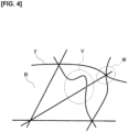
Figure 4 is a diagram for explaining factors that deteriorate the appearance of a molded article. -
Figure 5 is a diagram showing pattern elements of the first embodiment and modified examples thereof. -
Figure 6 is an exploded perspective view of a base material for molding according to a second embodiment. -
Figure 7 is a diagram showing pattern elements of the second embodiment and modified examples thereof. - Base materials for molding according to several embodiments will be described below with reference to the drawings.
- A base material for molding M1 according to the first embodiment includes two-dimensionally oriented reinforcing fibers F and a resin R with which the reinforcing fibers F are impregnated. The base material M1 is molded by means of a known molding method corresponding to the type of the resin R to be used, such as a heat-press method, an autoclave method, or a thermoforming method, in order to be molded into a molded article having a desired three-dimensional shape.
- As shown in
Figure 1 , the base material M1 can be formed by laminating, for example, eight prepregs, 1-8. Each of the prepregs 1-8 is a sheet-shaped composite material obtained by impregnating the reinforcing fibers F, which are aligned in one direction and arranged essentially parallel to each other, with the resin R as matrix material. The thickness of each of the prepregs 1-8 is not particularly limited, but is approximately 0.2 mm to 0.4 mm, for example. - The reinforcing fibers F in the prepregs 1-8 extend in a direction perpendicular to the stacking direction of the prepregs 1-8, that is, a direction perpendicular to the thickness direction of the base material M1 (hereinafter also referred to as the planar direction). The type of the reinforcing fibers F is not particularly limited; for example, carbon fibers, glass fibers, polyalamide fibers, alumina fibers, silicon carbide fibers, boron fibers, and carborundum fibers can be used. For example, polyacrylonitrile (PAN type), pitch type, cellulose type, carbon fibers from vapor phase-hydrocarbons, graphite fibers, etc., may be used as the carbon fibers. Two or more types of these fibers may be used in combination as well. The fineness, quantity, strength, elastic modulus, etc., of the reinforcing fibers F are not particularly limited. The volume content of the reinforcing fibers F in each of the prepregs 1-8 is not particularly limited, but may be set to, for example, 30% to 80%, so as to secure an appropriate state of impregnation of the resin R while suppressing the excessive flow of reinforcing fibers F during molding.
- The resin R as the matrix material is not particularly limited; for example, known thermosetting resins and thermoplastic resins, such as epoxy resin, phenol resin, unsaturated polyester resin, vinyl ester resin, polyimide resin, polycarbonate resin, polyamide resin, and polyphenylene sulfide (PPS) resin can be used.
- The method for preparing the prepregs 1-8 is not particularly limited, and a known method can be employed in accordance with the type, etc., of the resin R to be used. For example, if the resin R is a thermosetting resin, it is possible to use a hot melt method in which a thermosetting resin film is laminated and molded on a sheet-shaped fiber base material, or a solvent method in which a thermosetting resin is made into a varnish using an appropriate solvent and the fiber base material is impregnated therewith. In addition, if the resin R is a thermoplastic resin, it is possible to use a hot melt method, a solvent method, a powder method, a resin film impregnation method, a commingle method, etc.
- As shown in
Figure 1 , the eight prepregs 1-8 are laminated such that the reinforcing fibers F in the prepregs 1-8 are oriented at four different orientation angles. For example, the prepregs 1-8 can be laminated such that the reinforcing fibers F are oriented at orientation angles of 0°/45°/90°/-45°/-45°/90°/45°/0°, in order from the top inFigure 1 , so that the molded article obtained from the base material M1 has isotropic strength in the planar direction. - The "orientation angle" is the angle of the orientation direction of the reinforcing fibers F as seen from the thickness direction. That is, when the angle of the direction of a certain orientation of the reinforcing fibers F is set to 0°, it is the angle formed by the orientation direction of the target reinforcing fibers F with respect to this reference. When viewed from the front side of the base material M1 (upper side of
Figure 1 ), the counterclockwise direction with respect to the reference orientation direction is regarded as positive, and thus the angles should be greater than -90° and less than or equal to 90°. - Further, a state in which the reinforcing fibers F are "oriented at a certain orientation angle" is a state in which a fiber orientation parameter fp of the reinforcing fibers F is greater than or equal to 0.95. The fiber orientation parameter fp is a parameter that represents the orientation state of the reinforcing fibers F: fp = 1.0 means that the reinforcing fibers F are oriented parallel to a reference line, described further below; and fp = 0.0 means that the reinforcing fibers F are oriented completely random ly.
- The fiber orientation parameter fp can be obtained by means of the following method. First, a surface that is parallel to the planar direction including the reinforcing fibers F to be evaluated is cut out from the base material M1. This surface is then viewed through an optical microscope, etc., and the angles θi of all of the reinforcing fibers F (number of fibers: N) that can be visually recognized within a prescribed measurement region with respect to the reference line are measured. Here, the angles θi are positive in the counterclockwise direction with respect to the reference line, and are greater than -90° and less than or equal to 90°.
- Next, the obtained angles θi are substituted into the following equation (1).

- The direction of the reference line is selected such that the fiber orientation parameter fp of the reinforcing fibers F within a prescribed measurement region to be evaluated is given the maximum value. The selected direction is defined as the orientation direction of the reinforcing fibers F to be evaluated.
- As shown in
Figure 1 , in the present embodiment, of the four orientation angles, the reinforcing fibers F oriented at the orientation angles of 0°/90° are continuous fibers CF (the difference between the orientation angles of continuous fibers CF oriented at two orientation angles is 90°). In addition, of the four orientation angles, the reinforcing fibers F oriented at orientation angles other than 0°/90°, i.e., at 45°/-45°, are discontinuous fibers DF. The broken lines inFigure 1 represent the discontinuous fibers DF, whereas the solid lines represent the continuous fibers CF. - Here, "continuous fibers CF" are fibers in which the average fiber length of filaments constituting the reinforcing fibers F is 500 mm or more, and "discontinuous fibers DF" are fibers in which the average fiber length of filaments that constitute the reinforcing fibers F is greater than or equal to 10 mm and less than 500 mm. The average fiber length is a value obtained by dividing the sum of the squares of the fiber lengths of the filaments constituting the reinforcing fibers F by the sum of the fiber lengths of the filaments. The fiber length of the filaments can be measured by viewing the length of each of the filaments through an optical microscope, etc. The average fiber length of the filaments of the discontinuous fibers DF according to the present embodiment is preferably set to 10 mm or more and 200 mm or less. It is preferably 15 mm or more and 100 mm or less, and more preferably 20 mm or more and 100 mm or less. By setting the average fiber length of the discontinuous fibers DF within the range described above, it is possible to improve the strength of the molded article while maintaining excellent shaping properties of the base material M1.
- The reinforcing fibers F that are the discontinuous fibers DF may be aligned in a direction corresponding to each of the orientation angles and form, together with the resin R, a layer that does not intersect the reinforcing fibers F that are the continuous fibers CF. For example, as shown in
Figure 1 , the discontinuous fibers DF in theprepregs prepregs Figure 1 , the reinforcing fibers F that are the discontinuous fibers DF in theprepregs prepregs - The discontinuous fibers DF oriented at a certain orientation angle can be obtained by means of the following methods, for example. One example is a method in which a knife blade is pressed against, or laser light is irradiated upon, a one-direction prepreg obtained by impregnating the continuous fibers CF aligned in one direction with the resin R, to form cuts at an angles that intersect the fibers, and separating the continuous fibers CF. It is thereby possible to obtain discontinuous fibers DF that are aligned in one direction and that are essentially arranged parallel to each other. The length of each cut and the interval between cuts can be appropriately set in accordance with the required fiber length, etc., of the discontinuous fibers DF. Another example is a method in which a composition containing the resin R and the discontinuous fibers DF, the fiber lengths of which have been adjusted in advance, are extruded in a plastic region and pressure-molded into the form of a sheet, thereby obtaining a prepreg in which the discontinuous fibers DF are oriented in a certain direction.
- The action and effect of the present embodiment will be described below.
- First, for the sake of convenience, two-dimensionally oriented "pattern elements" of the reinforcing fibers F are defined.
Figure 2 is a diagram for explaining pattern elements that are defined from the reinforcing fibers F that are oriented at four orientation angles (0°/45°/90°/-45°). In the figure, the broken lines also represent the discontinuous fibers DF, whereas the solid lines represent the continuous fibers CF. If any three of the four orientation angles (0°/45°/90°/-45°) are selected, two triangular pattern elements can be defined for each combination of the selected orientation angles. For example, if 0°/45°/90° are selected, triangle ABC and triangle ACD can be defined as pattern elements. In addition, if 0°/45°/-45° are selected, triangle ABE and triangle CDE can be defined as pattern elements. Similarly, triangles ABD, BCD, BCE, and ADE can be defined as other pattern elements. That is, the simplest shape of a pattern element defined from the two-dimensionally oriented reinforcing fibers F is a triangle in which the reinforcing fibers F of the selected three orientation angles are the sides, and the points at which the reinforcing fibers F intersect are the apices. - (1) When a base material (comparative example), in which the reinforcing fibers F that are oriented at four orientation angles are all continuous fibers CF, is shaped into a three-dimensional form, each pattern element attempts to undergo shearing deformation in a plane parallel to the orientation of the reinforcing fibers F, as shown in
Figure 3 (particularly the U portion). In this deformed portion, the sizes of the angles of the triangle change, and a compressive force or a tensile force is generated at the reinforcing fibers F that constitute the sides of the triangle. Therefore, when the shearing deformation exceeds a certain limit, there is the possibility that the reinforcing fibers F will buckle due to the compressive force (refer to the V portion inFigure 4 ), or that wrinkles will occur on the surface of the base material due to the tensile force (refer to the W portion inFigure 4 ), thereby deteriorating the appearance of the molded article, as shown inFigure 4 . - In the present embodiment, on the other hand, certain reinforcing fibers F, the continuous fibers CF, are oriented at two of four orientation angles (0°/90°), and certain reinforcing fibers F, the discontinuous fibers DF, are oriented at the other two orientation angles (45°/-45°). Therefore, in any triangle of pattern elements, at least one side is composed of the discontinuous fibers DF. With regard to the discontinuous fibers DF, the divided fibers can move relative to each other in the fiber direction, so that axial forces (compressive force or tensile force) are less transmittable compared with the continuous fibers CF. Thus, when the pattern elements undergo in-plane shearing deformation, the forces that act on the continuous fibers CF via the apices of the triangles, i.e., the point of intersection with the discontinuous fibers DF, are reduced. Therefore, the axial forces that are generated in the reinforcing fibers F when the base material M1 is shaped into a three-dimensional form during molding are reduced, thereby preventing the reinforcing fibers F from buckling or forming wrinkles on the surface of the base material M1. As a result, the deterioration of the appearance of the molded article is suppressed. In addition, as a result of the reduction of axial forces that are generated in the reinforcing fibers F, the forces that restrain in-plane shearing deformation of the pattern elements are reduced, so that the shaping property of the base material M1 is improved.
- (2) Further, in the present embodiment, the reinforcing fibers F oriented at two of the four orientation angles are continuous fibers CF and the reinforcing fibers F oriented at the other orientation angles are discontinuous fibers DF. Therefore, compared to a case in which only the reinforcing fibers F oriented in one orientation angle (for example, 0°) are continuous fibers CF, the tensile strength of the molded article obtained by molding the base material M1 is improved. In addition, since the difference between the orientation angles of the continuous fibers CF is 90° and the absolute value of the difference is within the range of 85° or more and 95° or less, compared to a case in which the absolute value of the difference is outside of this range, the isotropic mechanical properties of the molded article are improved.
- (3) Moreover, in the present embodiment, the reinforcing fibers F that are the discontinuous fibers DF are aligned in a direction corresponding to each of the orientation angles and, together with the resin R, form a layer that does not intersect the reinforcing fibers F that are the continuous fibers CF. Therefore, compared to a case in which the layer of the discontinuous fibers DF intersects with the continuous fibers CF (for example, a case in which cuts are made only in the warp or the weft of a biaxial woven prepreg and used as the discontinuous fibers DF), each of the discontinuous fibers DF can more easily move in the fiber direction. Therefore, the force that acts on the continuous fibers CF from the discontinuous fibers DF is further reduced, thereby further improving the shaping property of the base material M1.
- (4) Further, in the present embodiment, the reinforcing fibers F that are the discontinuous fibers DF oriented at mutually different orientation angles each form a different layer. That is, the discontinuous fibers DF are arranged in different layers for each orientation angle. Therefore, compared to a case in which discontinuous fibers DF having different orientation angles are arranged in the same layer (for example, when cuts are made in both the warp and weft of a biaxial woven prepreg and used as the discontinuous fibers DF), each of the discontinuous fibers DF can more easily move in the fiber direction. Therefore, the shaping property of the base material M1 is further improved.
- In the first embodiment, the continuous fibers CF are oriented at 0°/90° and the discontinuous fibers DF are oriented at 45°/-45°, but the ways in which the orientation angles of the continuous fibers CF and the discontinuous fibers DF can be combined are not limited in this manner. For example, as shown in patterns P1 to P10 in
Figure 5 , the reinforcing fibers F oriented at any one or two of the four orientation angles may be the continuous fibers CF, and the reinforcing fibers F oriented at orientation angles other than the aforementioned one or two orientation angles may be the discontinuous fibers DF. InFigure 5 , "CF" represents the continuous fibers CF and "DF" represents the discontinuous fibers DF. The first column of the "pattern elements" column exemplifies the pattern element of triangle ABC inFigure 2 , and the second to fourth columns respectively exemplify the pattern elements of triangles ABD, ABE, and ADE. As is clear fromFigure 5 , in all of the patterns P1 to P10, at least one side of any triangle of any pattern element is composed of the discontinuous fibers DF, so that the effect described above can be obtained. Pattern P2 in the figure corresponds to the first embodiment. - A base material M2 according to a second embodiment will be described with reference to
Figures 6 and7 . In the second embodiment, configurations that are different from those of the first embodiment will be described, while configurations having the same functions as the configurations already described have been assigned similar reference symbols, and the descriptions thereof have been omitted. - As shown in
Figure 6 , the base material M2 for molding according to the second embodiment can be formed by laminating, for example, six prepregs, 11-16. - As shown in
Figure 6 , the six prepregs 11-16 are laminated such that the reinforcing fibers F in prepregs 11-16 are oriented at three different orientation angles. For example, prepregs 11-16 can be laminated such that the reinforcing fibers F are oriented at orientation angles of 0°/60°/-60°/-60°/60°/0°, in order from the top inFigure 6 , so that the molded article obtained from the base material M2 has isotropic strength in the planar direction. - As shown in
Figure 6 , in the present embodiment, of the three orientation angles, the reinforcing fibers F oriented at the orientation angles of 0°/-60° are continuous fibers CF. In addition, of the three orientation angles, the reinforcing fibers F oriented at orientation angles other than 0°/-60°, i.e., at 60°, are discontinuous fibers DF. The broken lines inFigure 6 represent the discontinuous fibers DF, whereas the solid lines represent the continuous fibers CF. - Also, in the present embodiment, the reinforcing fibers F that are the discontinuous fibers DF may be aligned in a direction that corresponds to each of the orientation angles and form, together with the resin R, a layer that does not intersect the reinforcing fibers F that are the continuous fibers CF. For example, as shown in
Figure 6 , the discontinuous fibers DF in theprepregs prepregs Figure 6 , the discontinuous fibers DF in theprepreg 12 of the second layer may form a layer different than the discontinuous fibers DF in theprepreg 14 of the fourth layer. - The action and effect of the present embodiment will be described below. In the present embodiment, an equilateral triangle pattern element can be defined from the reinforcing fibers F oriented in three orientation angles (0°/60°/-60°).
- In the present embodiment, the reinforcing fibers F oriented at two of the three orientation angles (0°/-60°) are continuous fibers CF and the reinforcing fibers F oriented at the other orientation angle (60°) are discontinuous fibers DF. Therefore, at least one side of the triangle of the pattern element is composed of the discontinuous fibers DF. Therefore, the effect of (1) above can also be obtained in this embodiment.
- In addition, in the present embodiment, the reinforcing fibers F that are the discontinuous fibers DF are aligned in a direction that correspond to each of the orientation angles and form, together with the resin R, a layer that does not intersect the reinforcing fibers F that are the continuous fibers CF. Further, the reinforcing fibers F that are the discontinuous fibers DF oriented at mutually different orientation angles each form a different layer. Therefore, the effects of (3) and (4) above can also be obtained in this embodiment.
- In the second embodiment, the continuous fibers CF are oriented at 0°/-60° and the discontinuous fibers DF are oriented at 60°, but the ways in which the orientation angles of the continuous fibers CF and the discontinuous fibers DF can be combined are not limited in this manner. For example, as shown by patterns P11 to P16 in
Figure 7 , the reinforcing fibers F oriented at one or two of the three orientation angles may be the continuous fibers CF, and the reinforcing fibers F oriented at orientation angles other than the aforementioned one or two orientation angles may be the discontinuous fibers DF. InFigure 7 , "CF" represents the continuous fibers CF and "DF" represents the discontinuous fibers DF. The "pattern element" column exemplifies each pattern element of patterns P11 to P16. As is clear fromFigure 7 , in all of the patterns P11 to P16, at least one side of any triangle of any pattern element is composed of the discontinuous fibers DF, so that the effect described above can be obtained. Pattern P12 in the figure corresponds to the second embodiment. - In the foregoing description, "two-dimensionally oriented reinforcing fibers F" means the reinforcing fibers F oriented in the planar direction of the base material. Reinforcing fibers oriented in the thickness direction of the base material and randomly oriented reinforcing fibers are not included in the "two-dimensionally oriented reinforcing fibers F." The form of the "two-dimensionally oriented reinforcing fibers F" includes cases in which the reinforcing fibers F are aligned in one direction and arranged in the form of a sheet as described above.
- In addition, the order of the orientation angles of the reinforcing fibers F of each layer of the base materials M1, M2 is not limited to those of the embodiments and the modified example. For example, in the first embodiment, the order was 0°/45°/90°/-45°/-45°/90°/45°/0° from the top down in
Figure 1 , but it may be 45°/- 45°/0°/90°/90°/-45°/45°. Further, the number of layers or the number of prepregs of the base materials M1, M2 is not particularly limited to the foregoing. Moreover, each layer of the base materials M1, M2 may be laminated such that the molded article has anisotropic strength in the planar direction. Further, a combination of two or more of the patterns P1-P16 shown inFigures 5 and7 may be used. - Several embodiments and modified examples were described above, but these embodiments, etc., are merely examples described in order to facilitate comprehension of the invention. The technical scope of the invention is not limited to the specific technical matters disclosed in the above-described embodiments, etc., and includes various modifications, changes, and alternatives that can be easily derived therefrom.
- The base materials M1, M2 for molding can be shaped into molded articles having the desired three-dimensional form. The obtained molded article can be applied to vehicular components, such as those for automobiles, for example, hoods, floor panels, door panels, bumpers, trunk lids, rear gates, fender panels, side body panels, and roof panels. In addition, the molded article can be utilized as component members of transport vehicles, such as those for aircraft, ships, railcars, etc., domestic electric appliances, power generation facilities, production machines, housing equipment, furniture, leisure goods, etc.
-
- M1, M2 Base materials for molding
- F Reinforcing fibers
- R Resin
- CF Continuous fibers
- DF Discontinuous fibers
Claims (4)
- A base material for molding (M1) comprising:reinforcing fibers (F) that are two-dimensionally oriented; anda resin (R) impregnated with the reinforcing fibers, whereinthe reinforcing fibers are oriented at three or more orientation angles that are different from one another,the reinforcing fibers oriented at one or two of the three or more orientation angles are continuous fibers (CF), andthe reinforcing fibers oriented at orientation angles other than the one or two orientation angles are discontinuous fibers (DF), where the reinforcing fibers are oriented at an orientation angle other than the one or two orientation angles in a divided state in the base material for molding,characterized in thatwhen there are continuous fibers oriented at the one of the orientation angles, the continuous fibers are oriented in a single direction;when there are continuous fibers oriented at the two of the orientation angles, the continuous fibers oriented at each of the two of the orientation angles are in different layers, with the continuous fibers being oriented in a single direction in each of the layers.
- The base material for molding according to claim 1, wherein the reinforcing fibers oriented at two of the three or more orientation angles are continuous fibers, the reinforcing fibers oriented at orientation angles other than the two orientation angles are discontinuous fibers, and an absolute value of a difference between the two of the orientation angles is between 85° and 95°, inclusive.
- The base material for molding according to claim 1 or 2, wherein the reinforcing fibers that are the discontinuous fibers are aligned in a direction that corresponds to each orientation angle and form, together with the resin, a layer that does not intersect reinforcing fibers that are the continuous fibers.
- The base material for molding according to claim 3, wherein the reinforcing fibers that are the discontinuous fibers oriented at mutually different orientation angles each form a different layer.
Applications Claiming Priority (1)
| Application Number | Priority Date | Filing Date | Title |
|---|---|---|---|
| PCT/IB2019/000337 WO2020194013A1 (en) | 2019-03-26 | 2019-03-26 | Forming-use base material |
Publications (3)
| Publication Number | Publication Date |
|---|---|
| EP3950250A1 EP3950250A1 (en) | 2022-02-09 |
| EP3950250A4 EP3950250A4 (en) | 2022-03-23 |
| EP3950250B1 true EP3950250B1 (en) | 2024-01-24 |
Family
ID=72610296
Family Applications (1)
| Application Number | Title | Priority Date | Filing Date |
|---|---|---|---|
| EP19920654.1A Active EP3950250B1 (en) | 2019-03-26 | 2019-03-26 | Forming-use base material |
Country Status (5)
| Country | Link |
|---|---|
| US (1) | US11731316B2 (en) |
| EP (1) | EP3950250B1 (en) |
| JP (1) | JP7347496B2 (en) |
| CN (1) | CN113631344B (en) |
| WO (1) | WO2020194013A1 (en) |
Families Citing this family (2)
| Publication number | Priority date | Publication date | Assignee | Title |
|---|---|---|---|---|
| CN112810189A (en) * | 2020-12-15 | 2021-05-18 | 重庆国际复合材料股份有限公司 | Light high-strength pallet panel, pallet and assembling method thereof |
| CN115246253B (en) * | 2021-12-24 | 2024-03-26 | 山东泰山体育器材有限公司 | Gymnastics apparatus load-bearing frame body and fiber structure body |
Family Cites Families (12)
| Publication number | Priority date | Publication date | Assignee | Title |
|---|---|---|---|---|
| JPS60178122U (en) * | 1984-05-07 | 1985-11-26 | 三菱レイヨン株式会社 | prepreg sheet |
| JPS6194726A (en) * | 1984-10-16 | 1986-05-13 | Mitsubishi Motors Corp | Fiber reinforced plastic molding material |
| JP2011084008A (en) * | 2009-10-16 | 2011-04-28 | Toyota Motor Corp | Molding method of fiber reinforced plastic laminate |
| JP2011121372A (en) * | 2011-01-24 | 2011-06-23 | Maruhachi Kk | Multi-shaft laminate reinforced fiber sheet manufacturing method, long inclination reinforced fiber sheet, and multi-shaft laminate reinforced fiber sheet |
| JP2013176876A (en) | 2012-02-28 | 2013-09-09 | Teijin Ltd | Manufacturing method of molding |
| JP6085798B2 (en) | 2012-06-27 | 2017-03-01 | 福井県 | COMPOSITE MATERIAL FOR 3D SHAPE FORMING AND ITS MANUFACTURING METHOD |
| JP6194726B2 (en) | 2013-09-30 | 2017-09-13 | ブラザー工業株式会社 | Conveying apparatus and recording apparatus having the same |
| US20170190123A1 (en) * | 2014-02-14 | 2017-07-06 | Mitsubishi Rayon Co., Ltd. | Fiber-reinforced plastic and production method therefor |
| JP6471377B2 (en) * | 2014-06-20 | 2019-02-20 | 学校法人同志社 | Prepreg laminate |
| KR20180097499A (en) * | 2015-12-25 | 2018-08-31 | 도레이 카부시키가이샤 | Base laminate and method for manufacturing fiber-reinforced plastic |
| US10532537B2 (en) | 2015-12-28 | 2020-01-14 | Toray Industries, Inc. | Sandwich structure, shaped product, and production processes therefor |
| WO2019031111A1 (en) * | 2017-08-10 | 2019-02-14 | 東レ株式会社 | Prepreg laminate, method for manufacturing fiber-reinforced plastic using prepreg laminate, and fiber-reinforced plastic |
-
2019
- 2019-03-26 CN CN201980094705.5A patent/CN113631344B/en active Active
- 2019-03-26 US US17/442,181 patent/US11731316B2/en active Active
- 2019-03-26 JP JP2021508086A patent/JP7347496B2/en active Active
- 2019-03-26 WO PCT/IB2019/000337 patent/WO2020194013A1/en unknown
- 2019-03-26 EP EP19920654.1A patent/EP3950250B1/en active Active
Also Published As
| Publication number | Publication date |
|---|---|
| WO2020194013A8 (en) | 2021-08-26 |
| JPWO2020194013A1 (en) | 2020-10-01 |
| WO2020194013A1 (en) | 2020-10-01 |
| US20220176593A1 (en) | 2022-06-09 |
| US11731316B2 (en) | 2023-08-22 |
| EP3950250A4 (en) | 2022-03-23 |
| EP3950250A1 (en) | 2022-02-09 |
| CN113631344A (en) | 2021-11-09 |
| JP7347496B2 (en) | 2023-09-20 |
| CN113631344B (en) | 2023-05-30 |
Similar Documents
| Publication | Publication Date | Title |
|---|---|---|
| EP3560698B1 (en) | Composite structure and method for manufacturing same | |
| JP6822147B2 (en) | Structure | |
| EP3950250B1 (en) | Forming-use base material | |
| EP3517564B1 (en) | Incised prepreg and method for producing incised prepreg | |
| EP3549741B1 (en) | Method for manufacturing fiber-reinforced resin molded article | |
| KR20150016083A (en) | Continuous fiber reinforced composite material and molded product thereof | |
| EP3476587A1 (en) | Sheet | |
| EP3578331B1 (en) | Method for producing fiber-reinforced plastic | |
| DE102010040301A1 (en) | Fiber-reinforced three-dimensional plastic molded part useful in aerospace industry, comprises continuous fiber layer, whose fibers are embedded in thermoplastic matrix, where molded part has surface formed form thermoplastic material | |
| US20160237227A1 (en) | Fiber reinforced thermoplastic resin member | |
| EP3578332B1 (en) | Method for producing fiber-reinforced plastic | |
| CN113853296B (en) | Reinforced core material for fan blade and preparation method thereof | |
| CN112399917A (en) | CFRP sheet, laminate using CFRP sheet, and method for producing CFRP sheet | |
| JP7385480B2 (en) | Laminate and method for manufacturing the laminate | |
| CA2801886C (en) | Method of making automotive body parts | |
| EP4067034A1 (en) | Fiber-reinforced composite material and sandwich structure | |
| EP4067033A1 (en) | Fiber-reinforced composite material and sandwich structure | |
| JP6965530B2 (en) | Notch prepreg and method of manufacturing notch prepreg | |
| EP4385714A1 (en) | Sheet-type fiber-reinforced composite having heterogeneous properties and mehtod for manufacturing the same |
Legal Events
| Date | Code | Title | Description |
|---|---|---|---|
| STAA | Information on the status of an ep patent application or granted ep patent |
Free format text: STATUS: THE INTERNATIONAL PUBLICATION HAS BEEN MADE |
|
| PUAI | Public reference made under article 153(3) epc to a published international application that has entered the european phase |
Free format text: ORIGINAL CODE: 0009012 |
|
| STAA | Information on the status of an ep patent application or granted ep patent |
Free format text: STATUS: REQUEST FOR EXAMINATION WAS MADE |
|
| 17P | Request for examination filed |
Effective date: 20211021 |
|
| AK | Designated contracting states |
Kind code of ref document: A1 Designated state(s): AL AT BE BG CH CY CZ DE DK EE ES FI FR GB GR HR HU IE IS IT LI LT LU LV MC MK MT NL NO PL PT RO RS SE SI SK SM TR |
|
| REG | Reference to a national code |
Ref country code: DE Ref legal event code: R079 Ref document number: 602019045850 Country of ref document: DE Free format text: PREVIOUS MAIN CLASS: B29B0015120000 Ipc: B29C0070080000 Ref legal event code: R079 Free format text: PREVIOUS MAIN CLASS: B29B0015120000 |
|
| RAP3 | Party data changed (applicant data changed or rights of an application transferred) |
Owner name: RENAULT S.A.S Owner name: NISSAN MOTOR CO., LTD. |
|
| A4 | Supplementary search report drawn up and despatched |
Effective date: 20220218 |
|
| RIC1 | Information provided on ipc code assigned before grant |
Ipc: B32B 5/26 20060101ALI20220215BHEP Ipc: B32B 5/12 20060101ALI20220215BHEP Ipc: B32B 5/02 20060101ALI20220215BHEP Ipc: B32B 5/28 20060101ALI20220215BHEP Ipc: C08J 5/04 20060101ALI20220215BHEP Ipc: B29C 70/08 20060101AFI20220215BHEP |
|
| DAV | Request for validation of the european patent (deleted) | ||
| DAX | Request for extension of the european patent (deleted) | ||
| RAP3 | Party data changed (applicant data changed or rights of an application transferred) |
Owner name: RENAULT S.A.S Owner name: NISSAN MOTOR CO., LTD. |
|
| STAA | Information on the status of an ep patent application or granted ep patent |
Free format text: STATUS: EXAMINATION IS IN PROGRESS |
|
| 17Q | First examination report despatched |
Effective date: 20230131 |
|
| GRAP | Despatch of communication of intention to grant a patent |
Free format text: ORIGINAL CODE: EPIDOSNIGR1 |
|
| STAA | Information on the status of an ep patent application or granted ep patent |
Free format text: STATUS: GRANT OF PATENT IS INTENDED |
|
| INTG | Intention to grant announced |
Effective date: 20231004 |
|
| GRAS | Grant fee paid |
Free format text: ORIGINAL CODE: EPIDOSNIGR3 |
|
| GRAA | (expected) grant |
Free format text: ORIGINAL CODE: 0009210 |
|
| STAA | Information on the status of an ep patent application or granted ep patent |
Free format text: STATUS: THE PATENT HAS BEEN GRANTED |
|
| AK | Designated contracting states |
Kind code of ref document: B1 Designated state(s): AL AT BE BG CH CY CZ DE DK EE ES FI FR GB GR HR HU IE IS IT LI LT LU LV MC MK MT NL NO PL PT RO RS SE SI SK SM TR |
|
| REG | Reference to a national code |
Ref country code: GB Ref legal event code: FG4D |
|
| REG | Reference to a national code |
Ref country code: CH Ref legal event code: EP |
|
| REG | Reference to a national code |
Ref country code: DE Ref legal event code: R096 Ref document number: 602019045850 Country of ref document: DE |
|
| REG | Reference to a national code |
Ref country code: IE Ref legal event code: FG4D |
|
| PGFP | Annual fee paid to national office [announced via postgrant information from national office to epo] |
Ref country code: DE Payment date: 20240321 Year of fee payment: 6 Ref country code: GB Payment date: 20240322 Year of fee payment: 6 |
|
| REG | Reference to a national code |
Ref country code: LT Ref legal event code: MG9D |
|
| REG | Reference to a national code |
Ref country code: NL Ref legal event code: MP Effective date: 20240124 |
|
| PGFP | Annual fee paid to national office [announced via postgrant information from national office to epo] |
Ref country code: FR Payment date: 20240319 Year of fee payment: 6 |
|
| PG25 | Lapsed in a contracting state [announced via postgrant information from national office to epo] |
Ref country code: NL Free format text: LAPSE BECAUSE OF FAILURE TO SUBMIT A TRANSLATION OF THE DESCRIPTION OR TO PAY THE FEE WITHIN THE PRESCRIBED TIME-LIMIT Effective date: 20240124 |
|
| PG25 | Lapsed in a contracting state [announced via postgrant information from national office to epo] |
Ref country code: NL Free format text: LAPSE BECAUSE OF FAILURE TO SUBMIT A TRANSLATION OF THE DESCRIPTION OR TO PAY THE FEE WITHIN THE PRESCRIBED TIME-LIMIT Effective date: 20240124 |
|
| PG25 | Lapsed in a contracting state [announced via postgrant information from national office to epo] |
Ref country code: IS Free format text: LAPSE BECAUSE OF FAILURE TO SUBMIT A TRANSLATION OF THE DESCRIPTION OR TO PAY THE FEE WITHIN THE PRESCRIBED TIME-LIMIT Effective date: 20240524 |
|
| PG25 | Lapsed in a contracting state [announced via postgrant information from national office to epo] |
Ref country code: LT Free format text: LAPSE BECAUSE OF FAILURE TO SUBMIT A TRANSLATION OF THE DESCRIPTION OR TO PAY THE FEE WITHIN THE PRESCRIBED TIME-LIMIT Effective date: 20240124 |
|
| PG25 | Lapsed in a contracting state [announced via postgrant information from national office to epo] |
Ref country code: GR Free format text: LAPSE BECAUSE OF FAILURE TO SUBMIT A TRANSLATION OF THE DESCRIPTION OR TO PAY THE FEE WITHIN THE PRESCRIBED TIME-LIMIT Effective date: 20240425 |
|
| REG | Reference to a national code |
Ref country code: AT Ref legal event code: MK05 Ref document number: 1651864 Country of ref document: AT Kind code of ref document: T Effective date: 20240124 |
|
| PG25 | Lapsed in a contracting state [announced via postgrant information from national office to epo] |
Ref country code: RS Free format text: LAPSE BECAUSE OF FAILURE TO SUBMIT A TRANSLATION OF THE DESCRIPTION OR TO PAY THE FEE WITHIN THE PRESCRIBED TIME-LIMIT Effective date: 20240424 Ref country code: HR Free format text: LAPSE BECAUSE OF FAILURE TO SUBMIT A TRANSLATION OF THE DESCRIPTION OR TO PAY THE FEE WITHIN THE PRESCRIBED TIME-LIMIT Effective date: 20240124 |
|
| PG25 | Lapsed in a contracting state [announced via postgrant information from national office to epo] |
Ref country code: ES Free format text: LAPSE BECAUSE OF FAILURE TO SUBMIT A TRANSLATION OF THE DESCRIPTION OR TO PAY THE FEE WITHIN THE PRESCRIBED TIME-LIMIT Effective date: 20240124 |
|
| PG25 | Lapsed in a contracting state [announced via postgrant information from national office to epo] |
Ref country code: AT Free format text: LAPSE BECAUSE OF FAILURE TO SUBMIT A TRANSLATION OF THE DESCRIPTION OR TO PAY THE FEE WITHIN THE PRESCRIBED TIME-LIMIT Effective date: 20240124 |
|
| PG25 | Lapsed in a contracting state [announced via postgrant information from national office to epo] |
Ref country code: RS Free format text: LAPSE BECAUSE OF FAILURE TO SUBMIT A TRANSLATION OF THE DESCRIPTION OR TO PAY THE FEE WITHIN THE PRESCRIBED TIME-LIMIT Effective date: 20240424 Ref country code: NO Free format text: LAPSE BECAUSE OF FAILURE TO SUBMIT A TRANSLATION OF THE DESCRIPTION OR TO PAY THE FEE WITHIN THE PRESCRIBED TIME-LIMIT Effective date: 20240424 Ref country code: LT Free format text: LAPSE BECAUSE OF FAILURE TO SUBMIT A TRANSLATION OF THE DESCRIPTION OR TO PAY THE FEE WITHIN THE PRESCRIBED TIME-LIMIT Effective date: 20240124 Ref country code: IS Free format text: LAPSE BECAUSE OF FAILURE TO SUBMIT A TRANSLATION OF THE DESCRIPTION OR TO PAY THE FEE WITHIN THE PRESCRIBED TIME-LIMIT Effective date: 20240524 Ref country code: HR Free format text: LAPSE BECAUSE OF FAILURE TO SUBMIT A TRANSLATION OF THE DESCRIPTION OR TO PAY THE FEE WITHIN THE PRESCRIBED TIME-LIMIT Effective date: 20240124 Ref country code: GR Free format text: LAPSE BECAUSE OF FAILURE TO SUBMIT A TRANSLATION OF THE DESCRIPTION OR TO PAY THE FEE WITHIN THE PRESCRIBED TIME-LIMIT Effective date: 20240425 Ref country code: FI Free format text: LAPSE BECAUSE OF FAILURE TO SUBMIT A TRANSLATION OF THE DESCRIPTION OR TO PAY THE FEE WITHIN THE PRESCRIBED TIME-LIMIT Effective date: 20240124 Ref country code: ES Free format text: LAPSE BECAUSE OF FAILURE TO SUBMIT A TRANSLATION OF THE DESCRIPTION OR TO PAY THE FEE WITHIN THE PRESCRIBED TIME-LIMIT Effective date: 20240124 Ref country code: BG Free format text: LAPSE BECAUSE OF FAILURE TO SUBMIT A TRANSLATION OF THE DESCRIPTION OR TO PAY THE FEE WITHIN THE PRESCRIBED TIME-LIMIT Effective date: 20240124 Ref country code: AT Free format text: LAPSE BECAUSE OF FAILURE TO SUBMIT A TRANSLATION OF THE DESCRIPTION OR TO PAY THE FEE WITHIN THE PRESCRIBED TIME-LIMIT Effective date: 20240124 |
|
| PG25 | Lapsed in a contracting state [announced via postgrant information from national office to epo] |
Ref country code: PL Free format text: LAPSE BECAUSE OF FAILURE TO SUBMIT A TRANSLATION OF THE DESCRIPTION OR TO PAY THE FEE WITHIN THE PRESCRIBED TIME-LIMIT Effective date: 20240124 Ref country code: PT Free format text: LAPSE BECAUSE OF FAILURE TO SUBMIT A TRANSLATION OF THE DESCRIPTION OR TO PAY THE FEE WITHIN THE PRESCRIBED TIME-LIMIT Effective date: 20240524 |
|
| PG25 | Lapsed in a contracting state [announced via postgrant information from national office to epo] |
Ref country code: SE Free format text: LAPSE BECAUSE OF FAILURE TO SUBMIT A TRANSLATION OF THE DESCRIPTION OR TO PAY THE FEE WITHIN THE PRESCRIBED TIME-LIMIT Effective date: 20240124 Ref country code: PT Free format text: LAPSE BECAUSE OF FAILURE TO SUBMIT A TRANSLATION OF THE DESCRIPTION OR TO PAY THE FEE WITHIN THE PRESCRIBED TIME-LIMIT Effective date: 20240524 Ref country code: PL Free format text: LAPSE BECAUSE OF FAILURE TO SUBMIT A TRANSLATION OF THE DESCRIPTION OR TO PAY THE FEE WITHIN THE PRESCRIBED TIME-LIMIT Effective date: 20240124 Ref country code: LV Free format text: LAPSE BECAUSE OF FAILURE TO SUBMIT A TRANSLATION OF THE DESCRIPTION OR TO PAY THE FEE WITHIN THE PRESCRIBED TIME-LIMIT Effective date: 20240124 |