WO2020194013A1 - Forming-use base material - Google Patents
Forming-use base material Download PDFInfo
- Publication number
- WO2020194013A1 WO2020194013A1 PCT/IB2019/000337 IB2019000337W WO2020194013A1 WO 2020194013 A1 WO2020194013 A1 WO 2020194013A1 IB 2019000337 W IB2019000337 W IB 2019000337W WO 2020194013 A1 WO2020194013 A1 WO 2020194013A1
- Authority
- WO
- WIPO (PCT)
- Prior art keywords
- fiber
- oriented
- reinforcing
- base material
- fibers
- Prior art date
Links
Images


Classifications
-
- B—PERFORMING OPERATIONS; TRANSPORTING
- B29—WORKING OF PLASTICS; WORKING OF SUBSTANCES IN A PLASTIC STATE IN GENERAL
- B29C—SHAPING OR JOINING OF PLASTICS; SHAPING OF MATERIAL IN A PLASTIC STATE, NOT OTHERWISE PROVIDED FOR; AFTER-TREATMENT OF THE SHAPED PRODUCTS, e.g. REPAIRING
- B29C70/00—Shaping composites, i.e. plastics material comprising reinforcements, fillers or preformed parts, e.g. inserts
- B29C70/04—Shaping composites, i.e. plastics material comprising reinforcements, fillers or preformed parts, e.g. inserts comprising reinforcements only, e.g. self-reinforcing plastics
- B29C70/06—Fibrous reinforcements only
- B29C70/08—Fibrous reinforcements only comprising combinations of different forms of fibrous reinforcements incorporated in matrix material, forming one or more layers, and with or without non-reinforced layers
- B29C70/081—Combinations of fibres of continuous or substantial length and short fibres
-
- B—PERFORMING OPERATIONS; TRANSPORTING
- B29—WORKING OF PLASTICS; WORKING OF SUBSTANCES IN A PLASTIC STATE IN GENERAL
- B29B—PREPARATION OR PRETREATMENT OF THE MATERIAL TO BE SHAPED; MAKING GRANULES OR PREFORMS; RECOVERY OF PLASTICS OR OTHER CONSTITUENTS OF WASTE MATERIAL CONTAINING PLASTICS
- B29B11/00—Making preforms
- B29B11/14—Making preforms characterised by structure or composition
- B29B11/16—Making preforms characterised by structure or composition comprising fillers or reinforcement
-
- B—PERFORMING OPERATIONS; TRANSPORTING
- B29—WORKING OF PLASTICS; WORKING OF SUBSTANCES IN A PLASTIC STATE IN GENERAL
- B29C—SHAPING OR JOINING OF PLASTICS; SHAPING OF MATERIAL IN A PLASTIC STATE, NOT OTHERWISE PROVIDED FOR; AFTER-TREATMENT OF THE SHAPED PRODUCTS, e.g. REPAIRING
- B29C70/00—Shaping composites, i.e. plastics material comprising reinforcements, fillers or preformed parts, e.g. inserts
- B29C70/04—Shaping composites, i.e. plastics material comprising reinforcements, fillers or preformed parts, e.g. inserts comprising reinforcements only, e.g. self-reinforcing plastics
- B29C70/06—Fibrous reinforcements only
- B29C70/10—Fibrous reinforcements only characterised by the structure of fibrous reinforcements, e.g. hollow fibres
- B29C70/16—Fibrous reinforcements only characterised by the structure of fibrous reinforcements, e.g. hollow fibres using fibres of substantial or continuous length
- B29C70/20—Fibrous reinforcements only characterised by the structure of fibrous reinforcements, e.g. hollow fibres using fibres of substantial or continuous length oriented in a single direction, e.g. roofing or other parallel fibres
- B29C70/205—Fibrous reinforcements only characterised by the structure of fibrous reinforcements, e.g. hollow fibres using fibres of substantial or continuous length oriented in a single direction, e.g. roofing or other parallel fibres the structure being shaped to form a three-dimensional configuration
- B29C70/207—Fibrous reinforcements only characterised by the structure of fibrous reinforcements, e.g. hollow fibres using fibres of substantial or continuous length oriented in a single direction, e.g. roofing or other parallel fibres the structure being shaped to form a three-dimensional configuration arranged in parallel planes of fibres crossing at substantial angles
-
- B—PERFORMING OPERATIONS; TRANSPORTING
- B32—LAYERED PRODUCTS
- B32B—LAYERED PRODUCTS, i.e. PRODUCTS BUILT-UP OF STRATA OF FLAT OR NON-FLAT, e.g. CELLULAR OR HONEYCOMB, FORM
- B32B5/00—Layered products characterised by the non- homogeneity or physical structure, i.e. comprising a fibrous, filamentary, particulate or foam layer; Layered products characterised by having a layer differing constitutionally or physically in different parts
- B32B5/02—Layered products characterised by the non- homogeneity or physical structure, i.e. comprising a fibrous, filamentary, particulate or foam layer; Layered products characterised by having a layer differing constitutionally or physically in different parts characterised by structural features of a fibrous or filamentary layer
- B32B5/08—Layered products characterised by the non- homogeneity or physical structure, i.e. comprising a fibrous, filamentary, particulate or foam layer; Layered products characterised by having a layer differing constitutionally or physically in different parts characterised by structural features of a fibrous or filamentary layer the fibres or filaments of a layer being of different substances, e.g. conjugate fibres, mixture of different fibres
-
- B—PERFORMING OPERATIONS; TRANSPORTING
- B32—LAYERED PRODUCTS
- B32B—LAYERED PRODUCTS, i.e. PRODUCTS BUILT-UP OF STRATA OF FLAT OR NON-FLAT, e.g. CELLULAR OR HONEYCOMB, FORM
- B32B5/00—Layered products characterised by the non- homogeneity or physical structure, i.e. comprising a fibrous, filamentary, particulate or foam layer; Layered products characterised by having a layer differing constitutionally or physically in different parts
- B32B5/02—Layered products characterised by the non- homogeneity or physical structure, i.e. comprising a fibrous, filamentary, particulate or foam layer; Layered products characterised by having a layer differing constitutionally or physically in different parts characterised by structural features of a fibrous or filamentary layer
- B32B5/12—Layered products characterised by the non- homogeneity or physical structure, i.e. comprising a fibrous, filamentary, particulate or foam layer; Layered products characterised by having a layer differing constitutionally or physically in different parts characterised by structural features of a fibrous or filamentary layer characterised by the relative arrangement of fibres or filaments of different layers, e.g. the fibres or filaments being parallel or perpendicular to each other
-
- B—PERFORMING OPERATIONS; TRANSPORTING
- B32—LAYERED PRODUCTS
- B32B—LAYERED PRODUCTS, i.e. PRODUCTS BUILT-UP OF STRATA OF FLAT OR NON-FLAT, e.g. CELLULAR OR HONEYCOMB, FORM
- B32B5/00—Layered products characterised by the non- homogeneity or physical structure, i.e. comprising a fibrous, filamentary, particulate or foam layer; Layered products characterised by having a layer differing constitutionally or physically in different parts
- B32B5/22—Layered products characterised by the non- homogeneity or physical structure, i.e. comprising a fibrous, filamentary, particulate or foam layer; Layered products characterised by having a layer differing constitutionally or physically in different parts characterised by the presence of two or more layers which are next to each other and are fibrous, filamentary, formed of particles or foamed
- B32B5/24—Layered products characterised by the non- homogeneity or physical structure, i.e. comprising a fibrous, filamentary, particulate or foam layer; Layered products characterised by having a layer differing constitutionally or physically in different parts characterised by the presence of two or more layers which are next to each other and are fibrous, filamentary, formed of particles or foamed one layer being a fibrous or filamentary layer
- B32B5/26—Layered products characterised by the non- homogeneity or physical structure, i.e. comprising a fibrous, filamentary, particulate or foam layer; Layered products characterised by having a layer differing constitutionally or physically in different parts characterised by the presence of two or more layers which are next to each other and are fibrous, filamentary, formed of particles or foamed one layer being a fibrous or filamentary layer another layer next to it also being fibrous or filamentary
-
- B—PERFORMING OPERATIONS; TRANSPORTING
- B32—LAYERED PRODUCTS
- B32B—LAYERED PRODUCTS, i.e. PRODUCTS BUILT-UP OF STRATA OF FLAT OR NON-FLAT, e.g. CELLULAR OR HONEYCOMB, FORM
- B32B7/00—Layered products characterised by the relation between layers; Layered products characterised by the relative orientation of features between layers, or by the relative values of a measurable parameter between layers, i.e. products comprising layers having different physical, chemical or physicochemical properties; Layered products characterised by the interconnection of layers
- B32B7/03—Layered products characterised by the relation between layers; Layered products characterised by the relative orientation of features between layers, or by the relative values of a measurable parameter between layers, i.e. products comprising layers having different physical, chemical or physicochemical properties; Layered products characterised by the interconnection of layers with respect to the orientation of features
-
- B—PERFORMING OPERATIONS; TRANSPORTING
- B29—WORKING OF PLASTICS; WORKING OF SUBSTANCES IN A PLASTIC STATE IN GENERAL
- B29C—SHAPING OR JOINING OF PLASTICS; SHAPING OF MATERIAL IN A PLASTIC STATE, NOT OTHERWISE PROVIDED FOR; AFTER-TREATMENT OF THE SHAPED PRODUCTS, e.g. REPAIRING
- B29C70/00—Shaping composites, i.e. plastics material comprising reinforcements, fillers or preformed parts, e.g. inserts
- B29C70/04—Shaping composites, i.e. plastics material comprising reinforcements, fillers or preformed parts, e.g. inserts comprising reinforcements only, e.g. self-reinforcing plastics
- B29C70/28—Shaping operations therefor
- B29C70/40—Shaping or impregnating by compression not applied
- B29C70/42—Shaping or impregnating by compression not applied for producing articles of definite length, i.e. discrete articles
-
- B—PERFORMING OPERATIONS; TRANSPORTING
- B32—LAYERED PRODUCTS
- B32B—LAYERED PRODUCTS, i.e. PRODUCTS BUILT-UP OF STRATA OF FLAT OR NON-FLAT, e.g. CELLULAR OR HONEYCOMB, FORM
- B32B2260/00—Layered product comprising an impregnated, embedded, or bonded layer wherein the layer comprises an impregnation, embedding, or binder material
- B32B2260/02—Composition of the impregnated, bonded or embedded layer
- B32B2260/021—Fibrous or filamentary layer
- B32B2260/023—Two or more layers
-
- B—PERFORMING OPERATIONS; TRANSPORTING
- B32—LAYERED PRODUCTS
- B32B—LAYERED PRODUCTS, i.e. PRODUCTS BUILT-UP OF STRATA OF FLAT OR NON-FLAT, e.g. CELLULAR OR HONEYCOMB, FORM
- B32B2260/00—Layered product comprising an impregnated, embedded, or bonded layer wherein the layer comprises an impregnation, embedding, or binder material
- B32B2260/04—Impregnation, embedding, or binder material
- B32B2260/046—Synthetic resin
-
- B—PERFORMING OPERATIONS; TRANSPORTING
- B32—LAYERED PRODUCTS
- B32B—LAYERED PRODUCTS, i.e. PRODUCTS BUILT-UP OF STRATA OF FLAT OR NON-FLAT, e.g. CELLULAR OR HONEYCOMB, FORM
- B32B2262/00—Composition or structural features of fibres which form a fibrous or filamentary layer or are present as additives
- B32B2262/02—Synthetic macromolecular fibres
- B32B2262/0261—Polyamide fibres
- B32B2262/0269—Aromatic polyamide fibres
-
- B—PERFORMING OPERATIONS; TRANSPORTING
- B32—LAYERED PRODUCTS
- B32B—LAYERED PRODUCTS, i.e. PRODUCTS BUILT-UP OF STRATA OF FLAT OR NON-FLAT, e.g. CELLULAR OR HONEYCOMB, FORM
- B32B2262/00—Composition or structural features of fibres which form a fibrous or filamentary layer or are present as additives
- B32B2262/10—Inorganic fibres
- B32B2262/101—Glass fibres
-
- B—PERFORMING OPERATIONS; TRANSPORTING
- B32—LAYERED PRODUCTS
- B32B—LAYERED PRODUCTS, i.e. PRODUCTS BUILT-UP OF STRATA OF FLAT OR NON-FLAT, e.g. CELLULAR OR HONEYCOMB, FORM
- B32B2262/00—Composition or structural features of fibres which form a fibrous or filamentary layer or are present as additives
- B32B2262/10—Inorganic fibres
- B32B2262/105—Ceramic fibres
-
- B—PERFORMING OPERATIONS; TRANSPORTING
- B32—LAYERED PRODUCTS
- B32B—LAYERED PRODUCTS, i.e. PRODUCTS BUILT-UP OF STRATA OF FLAT OR NON-FLAT, e.g. CELLULAR OR HONEYCOMB, FORM
- B32B2262/00—Composition or structural features of fibres which form a fibrous or filamentary layer or are present as additives
- B32B2262/10—Inorganic fibres
- B32B2262/106—Carbon fibres, e.g. graphite fibres
-
- B—PERFORMING OPERATIONS; TRANSPORTING
- B32—LAYERED PRODUCTS
- B32B—LAYERED PRODUCTS, i.e. PRODUCTS BUILT-UP OF STRATA OF FLAT OR NON-FLAT, e.g. CELLULAR OR HONEYCOMB, FORM
- B32B2262/00—Composition or structural features of fibres which form a fibrous or filamentary layer or are present as additives
- B32B2262/14—Mixture of at least two fibres made of different materials
-
- B—PERFORMING OPERATIONS; TRANSPORTING
- B32—LAYERED PRODUCTS
- B32B—LAYERED PRODUCTS, i.e. PRODUCTS BUILT-UP OF STRATA OF FLAT OR NON-FLAT, e.g. CELLULAR OR HONEYCOMB, FORM
- B32B2307/00—Properties of the layers or laminate
- B32B2307/70—Other properties
- B32B2307/706—Anisotropic
-
- B—PERFORMING OPERATIONS; TRANSPORTING
- B32—LAYERED PRODUCTS
- B32B—LAYERED PRODUCTS, i.e. PRODUCTS BUILT-UP OF STRATA OF FLAT OR NON-FLAT, e.g. CELLULAR OR HONEYCOMB, FORM
- B32B2307/00—Properties of the layers or laminate
- B32B2307/70—Other properties
- B32B2307/732—Dimensional properties
-
- B—PERFORMING OPERATIONS; TRANSPORTING
- B32—LAYERED PRODUCTS
- B32B—LAYERED PRODUCTS, i.e. PRODUCTS BUILT-UP OF STRATA OF FLAT OR NON-FLAT, e.g. CELLULAR OR HONEYCOMB, FORM
- B32B2479/00—Furniture
-
- B—PERFORMING OPERATIONS; TRANSPORTING
- B32—LAYERED PRODUCTS
- B32B—LAYERED PRODUCTS, i.e. PRODUCTS BUILT-UP OF STRATA OF FLAT OR NON-FLAT, e.g. CELLULAR OR HONEYCOMB, FORM
- B32B2509/00—Household appliances
-
- B—PERFORMING OPERATIONS; TRANSPORTING
- B32—LAYERED PRODUCTS
- B32B—LAYERED PRODUCTS, i.e. PRODUCTS BUILT-UP OF STRATA OF FLAT OR NON-FLAT, e.g. CELLULAR OR HONEYCOMB, FORM
- B32B2605/00—Vehicles
- B32B2605/08—Cars
-
- B—PERFORMING OPERATIONS; TRANSPORTING
- B32—LAYERED PRODUCTS
- B32B—LAYERED PRODUCTS, i.e. PRODUCTS BUILT-UP OF STRATA OF FLAT OR NON-FLAT, e.g. CELLULAR OR HONEYCOMB, FORM
- B32B2605/00—Vehicles
- B32B2605/10—Trains
-
- B—PERFORMING OPERATIONS; TRANSPORTING
- B32—LAYERED PRODUCTS
- B32B—LAYERED PRODUCTS, i.e. PRODUCTS BUILT-UP OF STRATA OF FLAT OR NON-FLAT, e.g. CELLULAR OR HONEYCOMB, FORM
- B32B2605/00—Vehicles
- B32B2605/12—Ships
-
- B—PERFORMING OPERATIONS; TRANSPORTING
- B32—LAYERED PRODUCTS
- B32B—LAYERED PRODUCTS, i.e. PRODUCTS BUILT-UP OF STRATA OF FLAT OR NON-FLAT, e.g. CELLULAR OR HONEYCOMB, FORM
- B32B2605/00—Vehicles
- B32B2605/18—Aircraft
Definitions
- the present invention relates to a base material for molding.
- Japanese Patent Application Laid-Open No. 2014-4797 discloses a composite material for molding.
- This molding composite material is formed by laminating and integrating a skin layer and a core layer.
- the skin layer is integrally formed of a thermoplastic resin material that becomes a matrix resin by aligning long fibers that become reinforcing fibers in a plane shape.
- the core layer is formed by integrally forming short fibers distributed in a plane with a thermoplastic resin material as a matrix resin.
- the reinforcing fibers may buckle due to the compressive force, or wrinkles may occur on the surface of the base material due to the tensile force, and the appearance of the molded product may deteriorate. There is.
- An object of the present invention is to provide a molding base material capable of suppressing deterioration of the appearance of a molded product.
- One aspect of the present invention is a molding base material in which reinforcing fibers are oriented at three or more different orientation angles.
- the reinforcing fibers oriented at one or two of the three or more orientation angles are continuous fibers, and the reinforcing fibers oriented at other orientation angles are discontinuous fibers.
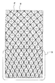
- FIG. 1 is an exploded perspective view of the molding base material according to the first embodiment.
- FIG. 2 is a diagram for explaining the pattern elements of the first embodiment.
- FIG. 3 is a diagram showing a state in which the pattern element is sheared and deformed.
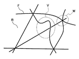
- FIG. 4 is a diagram for explaining factors that deteriorate the appearance of the molded product.
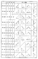
- FIG. 5 is a diagram showing pattern elements of the first embodiment and its modified examples.
- FIG. 6 is an exploded perspective view of the molding base material according to the second embodiment.
- FIG. 7 is a diagram showing pattern elements of the second embodiment and its modified example.
- the molding base material M1 according to the first embodiment includes a reinforcing fiber F oriented in two dimensions and a resin R impregnated in the reinforcing fiber F.
- the base material M1 is molded into a molded product having a desired three-dimensional shape by molding by a known molding method according to the type of resin R to be used, such as a heat pressing method, an autoclave method, or a thermoforming method. To.
- the base material M1 can be formed by laminating, for example, eight prepregs 1 to 8.
- Each of the prepregs 1 to 8 is a sheet-like composite material in which reinforcing fibers F aligned in one direction and arranged substantially parallel to each other are impregnated with resin R as a matrix material.
- the thickness of each prepreg 1 to 8 is not particularly limited, but is, for example, about 0.2 mm to 0.4 mm.
- the reinforcing fibers F in the prepregs 1 to 8 extend in a direction orthogonal to the laminating direction of the prepregs 1 to 8, that is, a direction orthogonal to the thickness direction of the base material M1 (hereinafter, also referred to as a plane direction).
- the type of the reinforcing fiber F is not particularly limited, and for example, carbon fiber, glass fiber, polyaramid fiber, alumina fiber, silicon carbide fiber, boron fiber, silicon carbide fiber and the like can be used.
- the carbon fiber for example, polyacrylonitrile (PAN-based), pitch-based, cellulose-based, hydrocarbon-based vapor-growth-based carbon fiber, graphite fiber, or the like can be used.
- the fineness, number of fibers, strength, elastic modulus, etc. of the reinforcing fiber F are not particularly limited.
- the volume content of the reinforcing fibers F in each of the prepregs 1 to 8 is not particularly limited, but for example, 30% to 80% in order to secure an appropriate impregnation state of the resin R while suppressing an excessive flow of the reinforcing fibers F during molding. Can be set to%.
- the resin R as the matrix material is not particularly limited, and for example, known heat curing such as epoxy resin, phenol resin, unsaturated polyester resin, vinyl ester resin, polyimide resin, polycarbonate resin, polyamide resin, and polyphenylene sulfide (PPS) resin.
- a sex resin or a thermoplastic resin can be used.
- the manufacturing method of the prepregs 1 to 8 is not particularly limited, and a known method can be adopted depending on the type of resin R to be used and the like.
- the resin R is a thermosetting resin
- a hot melt method in which a thermosetting resin film is laminated and molded on a sheet-shaped fiber base material and impregnated, or a varnish using a thermosetting resin in an appropriate solvent.
- a solvent method or the like in which the fiber base material is impregnated with the shape can be used.
- the resin R is a thermoplastic resin
- a hot melt method, a solvent method, a powder method, a resin film impregnation method, a commingle method, or the like can be used.
- the eight prepregs 1 to 8 are laminated so that the reinforcing fibers F in the prepregs 1 to 8 are oriented at four different orientation angles.
- the reinforcing fibers F are oriented at an orientation angle of 0 ° / 45 ° / 90 ° / ⁇ 45 ° / ⁇ 45 ° / 90 ° / 45 ° / 0 ° in order from the top of FIG. Therefore, the molded product obtained from the base material M1 can be laminated so as to have isotropic strength in the plane direction.
- the "orientation angle” is the angle in the orientation direction of the reinforcing fiber F in the thickness direction. That is, the angle of the orientation direction of the reinforcing fiber F as a reference is set to 0 °, and the angle formed by the orientation direction of the target reinforcing fiber F with respect to this reference.
- the angle is set to be positive counterclockwise from the reference orientation direction when viewed from the front side (upper side in FIG. 1) of the base material M1, and is an angle larger than ⁇ 90 ° and 90 ° or less.
- the state in which the reinforcing fiber F is "oriented at a certain orientation angle” means a state in which the fiber orientation parameter fp of the reinforcing fiber F is 0.95 or more.
- the fiber orientation parameter fp can be obtained by the following method. First, a plane parallel to the plane direction is cut out from the base material M1 including the reinforcing fiber F to be evaluated. Then, this surface is observed with an optical microscope or the like, and the angle ⁇ i with respect to the reference line of all the reinforcing fibers F (number of fibers: N) that can be visually recognized in a predetermined measurement region is measured.
- the angle ⁇ i is set to be positive counterclockwise from the reference line and set to an angle larger than ⁇ 90 ° and 90 ° or less.
- the direction of the reference line is selected so as to give the maximum value to the fiber orientation parameter fp for the reinforcing fiber F in the predetermined measurement region to be evaluated.
- the selected direction is defined as the orientation direction of the reinforcing fiber F to be evaluated.
- the reinforcing fiber F oriented at an orientation angle of 0 ° / 90 ° is a continuous fiber CF (continuous fiber CF oriented at two orientation angles). The difference in orientation angles between them is 90 °).
- the reinforcing fiber F oriented at an orientation angle of 45 ° / ⁇ 45 ° other than 0 ° / 90 ° is the discontinuous fiber DF.
- the broken line in FIG. 1 indicates the discontinuous fiber DF, and the solid line indicates the continuous fiber CF.
- the "continuous fiber CF” is a fiber having an average fiber length of 500 mm or more of the filaments constituting the reinforcing fiber F
- the “discontinuous fiber DF” is a fiber having an average fiber length of 10 mm of the filaments constituting the reinforcing fiber F. It is a fiber of 5 mm or more and less than 500 mm.
- the average fiber length is a value obtained by dividing the sum of the squares of the fiber lengths of the filaments constituting the reinforcing fiber F by the sum of the fiber lengths of the filaments.
- the fiber length of each filament can be measured by observing the length of each filament with an optical microscope or the like.
- the average fiber length of the filament of the discontinuous fiber DF in this embodiment is preferably set to 10 mm or more and 200 mm or less. It is preferably 15 mm or more and 100 mm or less, and more preferably 20 mm or more and 100 mm or less.
- the reinforcing fibers F which are discontinuous fiber DFs, are aligned in the directions corresponding to the respective orientation angles, and together with the resin R, a layer that does not intersect with the reinforcing fibers F, which is a continuous fiber CF, may be formed.
- the discontinuous fiber DF in the prepregs 2, 4, 5, 7 of the second, fourth, fifth, and seventh layers is the prepreg 1, of the first, third, sixth, and eighth layers.
- a layer that does not intersect with the continuous fiber CF in 3, 6 and 8 may be formed.
- the reinforcing fibers F, which are discontinuous fiber DFs oriented at different orientation angles may form different layers. For example, as shown in FIG.
- the reinforcing fiber F which is the discontinuous fiber DF in the prepregs 2 and 7 of the second and seventh layers, is the discontinuous fiber DF in the prepregs 4 and 5 of the fourth and fifth layers.
- a layer different from that of the reinforcing fiber F may be formed.
- the discontinuous fiber DF oriented at a certain orientation angle can be obtained by, for example, the following method. That is, for example, a blade is pressed against a unidirectional prepreg formed by impregnating continuous fiber CF aligned in one direction with resin R, or laser light is irradiated to make a notch at an angle intersecting the fiber to make the prepreg continuous. This is a method of dividing the fiber CF. As a result, discontinuous fiber DFs that are aligned in one direction and arranged substantially parallel to each other can be obtained. The length of each cut and the distance between the cuts can be appropriately set according to the required fiber length of the discontinuous fiber DF and the like.
- a composition containing a discontinuous fiber DF whose fiber length has been adjusted in advance and a resin R is extruded in a plastic region, and this is pressure-molded into a sheet shape.
- a method of obtaining a prepreg in which the continuous fiber DF is oriented in a certain direction is a method of obtaining a prepreg in which the continuous fiber DF is oriented in a certain direction.
- FIG. 2 is a diagram for explaining a pattern element defined by reinforcing fibers F oriented at four orientation angles (0 ° / 45 ° / 90 ° / ⁇ 45 °).
- the broken line indicates the discontinuous fiber DF
- the solid line indicates the continuous fiber CF.
- triangle ABC and triangle ACD can be defined as pattern elements.
- triangle ABE and triangle CDE can be defined as pattern elements.
- triangles ABD, BCD, BCE, and ADE can be defined as other pattern elements. That is, the simplest shape of the pattern element defined by the two-dimensionally oriented reinforcing fibers F is a triangle whose sides are the reinforcing fibers F having three selected orientation angles and whose apex is the point where the reinforcing fibers F intersect with each other. Is.
- each pattern element is shown in FIG. 3 (particularly the U portion). As shown, it attempts to shear deform in a plane parallel to the orientation of the reinforcing fibers F. In this deformed portion, the size of the angle of the triangle changes, and a compressive force or a tensile force is generated in the reinforcing fibers F constituting the side of the triangle. Therefore, when the amount of shear deformation exceeds a certain limit, as shown in FIG. 4, the reinforcing fiber F buckles due to the compressive force (see the V portion in FIG. 4), or the surface of the base material is wrinkled due to the tensile force. (Refer to the W part in FIG. 4), and the appearance of the molded product may deteriorate.
- the reinforcing fiber F oriented at two orientation angles (0 ° / 90 °) out of the four orientation angles is a continuous fiber CF, and the other orientation angles (45 ° / ⁇ ).
- the reinforcing fiber F oriented at 45 °) is a discontinuous fiber DF. Therefore, in any of the pattern element triangles, at least one side is composed of the discontinuous fiber DF. Since the discontinuous fiber DF can move the divided fibers relative to each other in the fiber direction, it is more difficult to transmit the axial force (compressive force and tensile force) than the continuous fiber CF.
- the force acting on the continuous fiber CF through the apex of the triangle, that is, the intersection with the discontinuous fiber DF is reduced. Therefore, at the time of molding, the axial force generated in the reinforcing fiber F when the base material M1 is shaped into a three-dimensional shape is reduced, the reinforcing fiber F buckles, and the surface of the base material M1 is wrinkled. Is suppressed. As a result, deterioration of the appearance of the molded product is suppressed. Further, by reducing the axial force generated in the reinforcing fiber F, the force for restraining the in-plane shear deformation of the pattern element is reduced, so that the shapeability of the base material M1 is improved.
- the reinforcing fiber F oriented at two of the four orientation angles is the continuous fiber CF
- the reinforcing fiber F oriented at the other orientation angles is the discontinuous fiber DF. is there. Therefore, the tensile strength of the molded product obtained by molding the base material M1 is improved as compared with the case where only the reinforcing fibers F oriented at one orientation angle (for example, 0 °) are the continuous fiber CF. Further, since the difference in the orientation angles of the continuous fiber CF is 90 ° and the absolute value of the difference is within the range of 85 ° or more and 95 ° or less, the machine of the molded product is compared with the case where the difference is outside the range. The isotropic properties of the target are improved.
- the reinforcing fibers F which are discontinuous fiber DFs, are aligned in the directions corresponding to the respective orientation angles, and together with the resin R, a layer that does not intersect with the reinforcing fibers F, which is the continuous fiber CF. Is forming. Therefore, compared with the case where the layer of the discontinuous fiber DF intersects with the continuous fiber CF (for example, when only one of the warp and weft of the biaxial woven prepreg is cut and used as the discontinuous fiber DF), each of them is compared. Discontinuous fiber DF easily moves in the fiber direction. Therefore, the force acting on the continuous fiber CF from the discontinuous fiber DF is further reduced, and the shapeability of the base material M1 is further improved.
- the reinforcing fibers F which are discontinuous fiber DFs oriented at different orientation angles, form different layers. That is, the discontinuous fiber DF is arranged in a different layer for each orientation angle. Therefore, compared with the case where discontinuous fiber DFs having different orientation angles are arranged in the same layer (for example, when both the warp and weft of the biaxial woven prepreg are cut to make them discontinuous fiber DFs), each of them is compared. Discontinuous fiber DF easily moves in the fiber direction. Therefore, the formability of the base material M1 is further improved.
- the continuous fiber CF was oriented at 0 ° / 90 ° and the discontinuous fiber DF was oriented at 45 ° / ⁇ 45 °, but the orientation angles of the continuous fiber CF and the discontinuous fiber DF.
- the combination of is not limited to this.
- the reinforcing fiber F oriented at any one or two orientation angles out of the four orientation angles is defined as a continuous fiber CF, and other than the one or two orientation angles.
- the reinforcing fiber F oriented at the orientation angle of can be a discontinuous fiber DF.
- "CF" represents continuous fiber CF
- DF represents discontinuous fiber DF.
- the first column in the "Pattern element” column exemplifies the pattern element of the triangle ABC of FIG. 2, and the second to fourth columns exemplify the pattern element of the triangle ABD, the triangle ABE, and the triangle ADE.
- the pattern P2 in the figure corresponds to the first embodiment.
- the molding base material M2 according to the second embodiment can be formed by laminating, for example, six prepregs 11 to 16.
- the six prepregs 11 to 16 are laminated so that the reinforcing fibers F in the prepregs 11 to 16 are oriented at three different orientation angles.
- the reinforcing fibers F are oriented at an orientation angle of 0 ° / 60 ° / -60 ° / -60 ° / 60 ° / 0 ° in order from the top of FIG. 6, and the base material M2
- the molded products obtained from the above can be laminated so as to have isotropic strength in the plane direction.
- the reinforcing fiber F oriented at an orientation angle of 0 ° / ⁇ 60 ° out of the three orientation angles is the continuous fiber CF.
- the reinforcing fiber F oriented at an orientation angle of 60 ° other than 0 ° / ⁇ 60 ° is the discontinuous fiber DF.
- the broken line in FIG. 6 indicates the discontinuous fiber DF, and the solid line indicates the continuous fiber CF.
- the reinforcing fibers F which are discontinuous fiber DFs are aligned in the directions corresponding to the respective orientation angles, and together with the resin R, form a layer which does not intersect with the reinforcing fibers F which is the continuous fiber CF.
- the discontinuous fiber DF in the prepregs 12 and 15 of the second and fifth layers is continuous in the prepregs 11, 13, 14 and 16 of the first, third, fourth and sixth layers. A layer that does not intersect the fiber CF may be formed.
- the reinforcing fibers F, which are discontinuous fiber DFs oriented at different orientation angles may form different layers.
- the discontinuous fiber DF in the prepreg 12 of the second layer may form a layer different from the discontinuous fiber DF in the prepreg 14 of the fourth layer.
- a regular triangular pattern element can be defined from the reinforcing fibers F oriented at three orientation angles (0 ° / 60 ° / ⁇ 60 °).
- the reinforcing fibers F oriented at two orientation angles (0 ° / ⁇ 60 °) are continuous fiber CFs, and the reinforcing fibers oriented at other orientation angles (60 °) are reinforcing fibers.
- the fiber F is a discontinuous fiber DF. Therefore, at least one side of the triangle of the pattern element is composed of the discontinuous fiber DF. Therefore, the effect of (1) above can be obtained also in this embodiment.
- the reinforcing fibers F which are discontinuous fiber DFs, are aligned in the directions corresponding to the respective orientation angles, and together with the resin R, form a layer that does not intersect with the reinforcing fibers F, which is the continuous fiber CF. ing. Further, the reinforcing fibers F, which are discontinuous fiber DFs oriented at different orientation angles, form different layers. Therefore, the effects of (3) and (4) above can be obtained also in this embodiment.
- the continuous fiber CF was oriented at 0 ° / ⁇ 60 ° and the discontinuous fiber DF was oriented at 60 °, but the combination of the orientation angles of the continuous fiber CF and the discontinuous fiber DF is different. , Not limited to this.
- the reinforcing fiber F oriented at any one or two orientation angles among the three orientation angles is defined as a continuous fiber CF, and other than the one or two orientation angles.
- the reinforcing fiber F oriented at the orientation angle of can be a discontinuous fiber DF.
- “CF” represents continuous fiber CF
- DF represents discontinuous fiber DF.
- the column of "pattern element” exemplifies each pattern element of patterns P11 to P16.
- the above effect can be obtained.
- the pattern P12 in the figure corresponds to the second embodiment.
- the "two-dimensionally oriented reinforcing fiber F” means the reinforcing fiber F oriented in the plane direction of the base material. Reinforcing fibers oriented in the thickness direction of the base material and randomly oriented reinforcing fibers are not included in "two-dimensionally oriented reinforcing fibers F".
- the form of the "two-dimensionally oriented reinforcing fiber F" is not particularly limited, and the reinforcing fibers F are aligned in one direction and arranged in a sheet shape as described above, as well as a biaxial woven fabric or a triaxial woven fabric. This includes the case where the reinforcing fibers F extending in the plane direction are interlaced with each other.
- the form of the reinforcing fiber F in any one or more layers of the base materials M1 and M2 according to the above embodiment and the modified example may be a biaxial woven fabric or a triaxial woven fabric.
- the biaxial woven fabric include woven fabrics woven by a method such as plain weave, twill weave, and satin weave.
- the order of the orientation angles of the reinforcing fibers F in each layer of the base materials M1 and M2 is not limited to that of the above-described embodiment and modification.
- it was 0 ° / 45 ° / 90 ° / ⁇ 45 ° / ⁇ 45 ° / 90 ° / 45 ° / 0 ° in order from the top of FIG. 1, but 45 ° / ⁇ 45. It may be ° / 0 ° / 90 ° / 90 ° / ⁇ 45 ° / 45 °.
- the number of layers of the base materials M1 and M2 or the number of prepregs is not limited to the above.
- the layers of the base materials M1 and M2 may be laminated so that the molded product has anisotropy in the plane direction.
- the patterns P1 to P16 shown in FIGS. 5 and 7 may be adopted in combination of any two or more.
- the molding base materials M1 and M2 can be molded into a molded product having a desired three-dimensional shape.
- the obtained molded product can be used as a constituent member of a vehicle such as an automobile such as a hood, a floor panel, a door panel, a bumper, a trunk lid, a rear gate, a fender panel, a side body panel, and a roof panel.
- the molded product can be used as a constituent member of a transport aircraft such as an aircraft, a ship, a railroad vehicle, a household electric product, a power generation facility, a production machine, a housing equipment, furniture, and leisure goods.
Abstract
The invention comprises forming-use base material (M1, M2) comprising reinforcement fibers (F) oriented at three or more orientation angles that are different from one another. In the base material (M1, M2), the reinforcement fibers (F) oriented at one or two orientation angles among the three or more orientation angles are continuous fibers (CF), and the reinforcement fibers (F) oriented at the other orientation angle(s) are discontinuous fibers (DF).
Description
本発明は、成形用基材に関する。
The present invention relates to a base material for molding.
特開2014−4797は、成形用複合材を開示している。この成形用複合材は、スキン層とコア層とを積層一体化して構成されている。スキン層は、強化繊維となる長繊維を面状に引き揃えてマトリックス樹脂となる熱可塑性樹脂材料により一体形成されている。
コア層は、面状に分布する短繊維をマトリックス樹脂となる熱可塑性樹脂材料により一体形成されている。 Japanese Patent Application Laid-Open No. 2014-4797 discloses a composite material for molding. This molding composite material is formed by laminating and integrating a skin layer and a core layer. The skin layer is integrally formed of a thermoplastic resin material that becomes a matrix resin by aligning long fibers that become reinforcing fibers in a plane shape.
The core layer is formed by integrally forming short fibers distributed in a plane with a thermoplastic resin material as a matrix resin.
ところで、二次元に配向した強化繊維に樹脂を含浸させてなる基材を三次元形状に賦形すると、少なくともその基材の一部が、強化繊維の配向に平行な面内でせん断変形する。この変形部分では、面内の主応力方向またはこれに近い方向に配向した強化繊維において、それ以外の方向に配向した強化繊維よりも大きな圧縮力または引張力が発生する。そして、せん断変形量がある限度を超えた場合には、上記圧縮力によって強化繊維が座屈したり、上記引張力によって基材表面に皺が生じたりして、成形品の見栄えが悪化する可能性がある。
By the way, when a base material formed by impregnating a two-dimensionally oriented reinforcing fiber with a resin into a three-dimensional shape, at least a part of the base material is shear-deformed in a plane parallel to the orientation of the reinforcing fiber. In this deformed portion, a compressive force or a tensile force is generated in the reinforcing fibers oriented in the direction of the principal stress in the plane or in a direction close thereto, as compared with the reinforcing fibers oriented in other directions. When the amount of shear deformation exceeds a certain limit, the reinforcing fibers may buckle due to the compressive force, or wrinkles may occur on the surface of the base material due to the tensile force, and the appearance of the molded product may deteriorate. There is.
本発明の目的は、成形品の見栄えの悪化を抑制できる成形用基材を提供することにある。
An object of the present invention is to provide a molding base material capable of suppressing deterioration of the appearance of a molded product.
本発明の一態様は、強化繊維が互いに異なる3つ以上の配向角度で配向した成形用基材である。この基材では、上記3つ以上の配向角度のうち1つまたは2つの配向角度で配向した強化繊維は連続繊維であり、それ以外の配向角度で配向した強化繊維は不連続繊維である。
One aspect of the present invention is a molding base material in which reinforcing fibers are oriented at three or more different orientation angles. In this base material, the reinforcing fibers oriented at one or two of the three or more orientation angles are continuous fibers, and the reinforcing fibers oriented at other orientation angles are discontinuous fibers.
上記成形用基材によれば、成形品の見栄えの悪化を抑制することができる。
According to the above-mentioned molding base material, deterioration of the appearance of the molded product can be suppressed.
以下、いくつかの実施形態にかかる成形用基材について、図面を参照しながら説明する。
Hereinafter, the molding base material according to some embodiments will be described with reference to the drawings.
<第1実施形態>
第1実施形態にかかる成形用基材M1は、二次元に配向した強化繊維Fと、強化繊維Fに含浸された樹脂Rと、を備えている。基材M1は、例えば、加熱プレス法、オートクレーブ法、熱成形法など、使用する樹脂Rの種類に応じた公知の成形方法で成形することで、所望の三次元形状を有する成形品に成形される。 <First Embodiment>
The molding base material M1 according to the first embodiment includes a reinforcing fiber F oriented in two dimensions and a resin R impregnated in the reinforcing fiber F. The base material M1 is molded into a molded product having a desired three-dimensional shape by molding by a known molding method according to the type of resin R to be used, such as a heat pressing method, an autoclave method, or a thermoforming method. To.
基材M1は、図1に示すように、例えば8枚のプリプレグ1~8を積層して形成することができる。各プリプレグ1~8は、一方向に引き揃えられ実質的に互いに平行に配置された強化繊維Fに、マトリックス材としての樹脂Rを含浸させたシート状の複合材料である。各プリプレグ1~8の厚さは、特に限定されないが、例えば0.2mm~0.4mm程度である。
As shown in FIG. 1, the base material M1 can be formed by laminating, for example, eight prepregs 1 to 8. Each of the prepregs 1 to 8 is a sheet-like composite material in which reinforcing fibers F aligned in one direction and arranged substantially parallel to each other are impregnated with resin R as a matrix material. The thickness of each prepreg 1 to 8 is not particularly limited, but is, for example, about 0.2 mm to 0.4 mm.
プリプレグ1~8中の強化繊維Fは、プリプレグ1~8の積層方向と直交する方向、すなわち基材M1の厚さ方向と直交する方向(以下、面方向とも称する)に延びている。強化繊維Fの種類は、特に限定されず、例えば、炭素繊維、ガラス繊維、ポリアラミド繊維、アルミナ繊維、シリコンカーバイド繊維、ボロン繊維、炭化ケイ素繊維などを用いることができる。炭素繊維は、例えば、ポリアクリロニトリル(PAN系)、ピッチ系、セルロース系、炭化水素による気相成長系炭素繊維、黒鉛繊維などを用いることができる。これらの繊維を2種類以上組み合わせて用いてもよい。強化繊維Fの繊度、繊維本数、強度、弾性率等は、特に限定されない。各プリプレグ1~8における強化繊維Fの体積含有率は、特に限定されないが、成形時の強化繊維Fの過剰な流動を抑えつつ樹脂Rの適度な含浸状態を確保するべく、例えば30%~80%に設定することができる。
The reinforcing fibers F in the prepregs 1 to 8 extend in a direction orthogonal to the laminating direction of the prepregs 1 to 8, that is, a direction orthogonal to the thickness direction of the base material M1 (hereinafter, also referred to as a plane direction). The type of the reinforcing fiber F is not particularly limited, and for example, carbon fiber, glass fiber, polyaramid fiber, alumina fiber, silicon carbide fiber, boron fiber, silicon carbide fiber and the like can be used. As the carbon fiber, for example, polyacrylonitrile (PAN-based), pitch-based, cellulose-based, hydrocarbon-based vapor-growth-based carbon fiber, graphite fiber, or the like can be used. Two or more kinds of these fibers may be used in combination. The fineness, number of fibers, strength, elastic modulus, etc. of the reinforcing fiber F are not particularly limited. The volume content of the reinforcing fibers F in each of the prepregs 1 to 8 is not particularly limited, but for example, 30% to 80% in order to secure an appropriate impregnation state of the resin R while suppressing an excessive flow of the reinforcing fibers F during molding. Can be set to%.
マトリックス材としての樹脂Rは、特に限定されず、例えば、エポキシ樹脂、フェノール樹脂、不飽和ポリエステル樹脂、ビニルエステル樹脂、ポリイミド樹脂、ポリカーボネート樹脂、ポリアミド樹脂、ポリフェニレンスルフィド(PPS)樹脂など公知の熱硬化性樹脂や熱可塑性樹脂を用いることができる。
The resin R as the matrix material is not particularly limited, and for example, known heat curing such as epoxy resin, phenol resin, unsaturated polyester resin, vinyl ester resin, polyimide resin, polycarbonate resin, polyamide resin, and polyphenylene sulfide (PPS) resin. A sex resin or a thermoplastic resin can be used.
プリプレグ1~8の製法は、特に限定されず、使用する樹脂Rの種類等に応じて公知の方法を採用することができる。例えば、樹脂Rが熱硬化性樹脂である場合は、熱硬化性樹脂フィルムをシート状の繊維基材に積層成形して含浸させるホットメルト法や、熱硬化性樹脂を適当な溶媒を用いてワニス状にし、これを繊維基材に含浸させる溶剤法などを用いることができる。また、樹脂Rが熱可塑性樹脂である場合は、ホットメルト法、溶剤法、パウダー法、樹脂フィルム含浸法、コミングル法などを用いることができる。
The manufacturing method of the prepregs 1 to 8 is not particularly limited, and a known method can be adopted depending on the type of resin R to be used and the like. For example, when the resin R is a thermosetting resin, a hot melt method in which a thermosetting resin film is laminated and molded on a sheet-shaped fiber base material and impregnated, or a varnish using a thermosetting resin in an appropriate solvent. A solvent method or the like in which the fiber base material is impregnated with the shape can be used. When the resin R is a thermoplastic resin, a hot melt method, a solvent method, a powder method, a resin film impregnation method, a commingle method, or the like can be used.
8枚のプリプレグ1~8は、図1に示すように、プリプレグ1~8中の強化繊維Fが互いに異なる4つの配向角度で配向するように積層されている。プリプレグ1~8は、強化繊維Fが、例えば、図1の上から順に0°/45°/90°/−45°/−45°/90°/45°/0°の配向角度で配向して、基材M1から得られる成形品が面方向において強度的に等方性を備えるように積層することができる。
As shown in FIG. 1, the eight prepregs 1 to 8 are laminated so that the reinforcing fibers F in the prepregs 1 to 8 are oriented at four different orientation angles. In the prepregs 1 to 8, for example, the reinforcing fibers F are oriented at an orientation angle of 0 ° / 45 ° / 90 ° / −45 ° / −45 ° / 90 ° / 45 ° / 0 ° in order from the top of FIG. Therefore, the molded product obtained from the base material M1 can be laminated so as to have isotropic strength in the plane direction.
なお、「配向角度」とは、厚さ方向視における強化繊維Fの配向方向の角度である。すなわち、ある基準となる強化繊維Fの配向方向の角度を0°とし、この基準に対して、対象とする強化繊維Fの配向方向がなす角度である。角度の取り方は、基材M1の表側(図1の上側)からみたときに、基準の配向方向から反時計回りを正とし、−90°より大きく90°以下の角度とする。
The "orientation angle" is the angle in the orientation direction of the reinforcing fiber F in the thickness direction. That is, the angle of the orientation direction of the reinforcing fiber F as a reference is set to 0 °, and the angle formed by the orientation direction of the target reinforcing fiber F with respect to this reference. The angle is set to be positive counterclockwise from the reference orientation direction when viewed from the front side (upper side in FIG. 1) of the base material M1, and is an angle larger than −90 ° and 90 ° or less.
また、強化繊維Fが「ある配向角度で配向した」状態とは、強化繊維Fの繊維配向パラメータfpが、0.95以上である状態をいう。繊維配向パラメータfpは、強化繊維Fの配向状態を表すパラメータであり、fp=1.0のとき、強化繊維Fが後述する基準線と平行に配向していることを意味し、fp=0.0のとき、強化繊維Fが完全にランダムに配向されていることを意味する。
Further, the state in which the reinforcing fiber F is "oriented at a certain orientation angle" means a state in which the fiber orientation parameter fp of the reinforcing fiber F is 0.95 or more. The fiber orientation parameter fp is a parameter representing the orientation state of the reinforcing fiber F, and when fp = 1.0, it means that the reinforcing fiber F is oriented parallel to the reference line described later, and fp = 0. When it is 0, it means that the reinforcing fibers F are completely randomly oriented.
繊維配向パラメータfpは、次の方法で求めることができる。まず、基材M1から、評価対象となる強化繊維Fを含む、面方向に平行な面を切り出す。そして、この面を光学顕微鏡等で観察し、所定の測定領域で視認し得るすべての強化繊維F(繊維数:N本)の基準線に対する角度θiを測定する。ここで、角度θiは、基準線から反時計回りを正とし、−90°より大きく90°以下の角度とする。
The fiber orientation parameter fp can be obtained by the following method. First, a plane parallel to the plane direction is cut out from the base material M1 including the reinforcing fiber F to be evaluated. Then, this surface is observed with an optical microscope or the like, and the angle θi with respect to the reference line of all the reinforcing fibers F (number of fibers: N) that can be visually recognized in a predetermined measurement region is measured. Here, the angle θi is set to be positive counterclockwise from the reference line and set to an angle larger than −90 ° and 90 ° or less.
次に、得られた角度θiを、次式(1)に代入する。
fp=2×Σ(cos2θi/N)−1 ・・・式(1)
ただし、i=1~N Next, the obtained angle θi is substituted into the following equation (1).
fp = 2 × Σ (cos 2 θi / N) -1 ... Equation (1)
However, i = 1 to N
fp=2×Σ(cos2θi/N)−1 ・・・式(1)
ただし、i=1~N Next, the obtained angle θi is substituted into the following equation (1).
fp = 2 × Σ (cos 2 θi / N) -1 ... Equation (1)
However, i = 1 to N
基準線の方向は、評価対象となっている所定の測定領域内の強化繊維Fに対して、その繊維配向パラメータfpに最大値を与えるように選択される。選択された方向は、当該評価対象となっている強化繊維Fの配向方向として定義される。
The direction of the reference line is selected so as to give the maximum value to the fiber orientation parameter fp for the reinforcing fiber F in the predetermined measurement region to be evaluated. The selected direction is defined as the orientation direction of the reinforcing fiber F to be evaluated.
本実施形態では、図1に示すように、4つの配向角度のうち、0°/90°の配向角度で配向した強化繊維Fが連続繊維CFである(2つの配向角度で配向した連続繊維CF同士の配向角度の差は90°である)。また、4つの配向角度のうち、0°/90°以外の45°/−45°の配向角度で配向した強化繊維Fが不連続繊維DFである。図1における破線が不連続繊維DFを、実線が連続繊維CFを示している。
In the present embodiment, as shown in FIG. 1, of the four orientation angles, the reinforcing fiber F oriented at an orientation angle of 0 ° / 90 ° is a continuous fiber CF (continuous fiber CF oriented at two orientation angles). The difference in orientation angles between them is 90 °). Of the four orientation angles, the reinforcing fiber F oriented at an orientation angle of 45 ° / −45 ° other than 0 ° / 90 ° is the discontinuous fiber DF. The broken line in FIG. 1 indicates the discontinuous fiber DF, and the solid line indicates the continuous fiber CF.
ここで、「連続繊維CF」は、強化繊維Fを構成するフィラメントの平均繊維長が500mm以上の繊維であり、「不連続繊維DF」は、強化繊維Fを構成するフィラメントの平均繊維長が10mm以上500mm未満の繊維である。平均繊維長は、強化繊維Fを構成する各フィラメントの繊維長の二乗の総和を各フィラメントの繊維長の総和で除した値である。各フィラメントの繊維長は、フィラメントのそれぞれの長さを光学顕微鏡等で観察することにより測定することができる。本実施形態における不連続繊維DFのフィラメントの平均繊維長は、10mm以上200mm以下に設定するとよい。好ましくは、15mm以上100mm以下、さらに好ましくは、20mm以上100mm以下である。不連続繊維DFの平均繊維長を上記範囲内に設定することにより、基材M1の優れた賦形性を維持しつつ成形品の強度を良好なものとすることができる。
Here, the "continuous fiber CF" is a fiber having an average fiber length of 500 mm or more of the filaments constituting the reinforcing fiber F, and the "discontinuous fiber DF" is a fiber having an average fiber length of 10 mm of the filaments constituting the reinforcing fiber F. It is a fiber of 5 mm or more and less than 500 mm. The average fiber length is a value obtained by dividing the sum of the squares of the fiber lengths of the filaments constituting the reinforcing fiber F by the sum of the fiber lengths of the filaments. The fiber length of each filament can be measured by observing the length of each filament with an optical microscope or the like. The average fiber length of the filament of the discontinuous fiber DF in this embodiment is preferably set to 10 mm or more and 200 mm or less. It is preferably 15 mm or more and 100 mm or less, and more preferably 20 mm or more and 100 mm or less. By setting the average fiber length of the discontinuous fiber DF within the above range, it is possible to improve the strength of the molded product while maintaining the excellent shapeability of the base material M1.
不連続繊維DFである強化繊維Fは、各々の配向角度に対応する方向に引き揃えられ、樹脂Rとともに、連続繊維CFである強化繊維Fと交差しない層を形成してもよい。例えば、図1に示すように、第2,4,5,7層目のプリプレグ2,4,5,7中の不連続繊維DFは、第1,3,6,8層目のプリプレグ1,3,6,8中の連続繊維CFと交差しない層を形成してもよい。また、互いに異なる配向角度で配向した不連続繊維DFである強化繊維Fは、それぞれ別の層を形成してもよい。例えば、図1に示すように、第2,7層目のプリプレグ2,7中の不連続繊維DFである強化繊維Fは、第4,5層目のプリプレグ4,5中の不連続繊維DFである強化繊維Fと別の層を形成してもよい。
The reinforcing fibers F, which are discontinuous fiber DFs, are aligned in the directions corresponding to the respective orientation angles, and together with the resin R, a layer that does not intersect with the reinforcing fibers F, which is a continuous fiber CF, may be formed. For example, as shown in FIG. 1, the discontinuous fiber DF in the prepregs 2, 4, 5, 7 of the second, fourth, fifth, and seventh layers is the prepreg 1, of the first, third, sixth, and eighth layers. A layer that does not intersect with the continuous fiber CF in 3, 6 and 8 may be formed. Further, the reinforcing fibers F, which are discontinuous fiber DFs oriented at different orientation angles, may form different layers. For example, as shown in FIG. 1, the reinforcing fiber F, which is the discontinuous fiber DF in the prepregs 2 and 7 of the second and seventh layers, is the discontinuous fiber DF in the prepregs 4 and 5 of the fourth and fifth layers. A layer different from that of the reinforcing fiber F may be formed.
ある配向角度で配向した不連続繊維DFは、例えば、以下の方法で得ることができる。すなわち、一方向に引き揃えられた連続繊維CFに樹脂Rを含浸させてなる一方向プリプレグに対し、例えば刃を押し付け、またはレーザー光を照射して、繊維と交差する角度に切込みを入れ、連続繊維CFを分断する方法である。これにより、一方向に引き揃えられ、実質的に互いに平行に配置された不連続繊維DFを得ることができる。各切込みの長さ、切込み同士の間の間隔は、必要とする不連続繊維DFの繊維長等に応じて適宜設定することができる。また、他の方法としては、例えば、予め繊維長を調整された不連続繊維DFと樹脂Rとを含む組成物を塑性域で押出成形し、これをシート状に加圧成形することで、不連続繊維DFが一定の方向に配向したプリプレグを得る方法などがある。
The discontinuous fiber DF oriented at a certain orientation angle can be obtained by, for example, the following method. That is, for example, a blade is pressed against a unidirectional prepreg formed by impregnating continuous fiber CF aligned in one direction with resin R, or laser light is irradiated to make a notch at an angle intersecting the fiber to make the prepreg continuous. This is a method of dividing the fiber CF. As a result, discontinuous fiber DFs that are aligned in one direction and arranged substantially parallel to each other can be obtained. The length of each cut and the distance between the cuts can be appropriately set according to the required fiber length of the discontinuous fiber DF and the like. Further, as another method, for example, a composition containing a discontinuous fiber DF whose fiber length has been adjusted in advance and a resin R is extruded in a plastic region, and this is pressure-molded into a sheet shape. There is a method of obtaining a prepreg in which the continuous fiber DF is oriented in a certain direction.
以下、本実施形態の作用効果について説明する。
Hereinafter, the action and effect of this embodiment will be described.
まず、説明の便宜のため、強化繊維Fの二次元配向の「パターン要素」を定義する。図2は、4つの配向角度(0°/45°/90°/−45°)で配向した強化繊維Fから定義されるパターン要素を説明するための図である。同図においても、破線が不連続繊維DFを、実線が連続繊維CFを示している。いま、4つの配向角度(0°/45°/90°/−45°)のうち任意に3つの配向角度を選択すると、選択した配向角度の組み合わせから2つずつ三角形状のパターン要素を定義できる。例えば、0°/45°/90°を選択した場合は、パターン要素として三角形ABC及び三角形ACDを定義できる。また、0°/45°/−45°を選択した場合は、パターン要素として三角形ABE及び三角形CDEを定義できる。同様に他のパターン要素として、三角形ABD、BCD、BCE、及びADEを定義できる。すなわち、二次元に配向した強化繊維Fから定義されるパターン要素の最も単純な形状は、選択した3つの配向角度の強化繊維Fを辺とし、当該強化繊維F同士が交わる点を頂点とする三角形である。
First, for convenience of explanation, the "pattern element" of the two-dimensional orientation of the reinforcing fiber F is defined. FIG. 2 is a diagram for explaining a pattern element defined by reinforcing fibers F oriented at four orientation angles (0 ° / 45 ° / 90 ° / −45 °). In the figure as well, the broken line indicates the discontinuous fiber DF, and the solid line indicates the continuous fiber CF. Now, if you select any three orientation angles from the four orientation angles (0 ° / 45 ° / 90 ° / -45 °), you can define two triangular pattern elements from the combination of the selected orientation angles. .. For example, when 0 ° / 45 ° / 90 ° is selected, triangle ABC and triangle ACD can be defined as pattern elements. When 0 ° / 45 ° / −45 ° is selected, triangle ABE and triangle CDE can be defined as pattern elements. Similarly, triangles ABD, BCD, BCE, and ADE can be defined as other pattern elements. That is, the simplest shape of the pattern element defined by the two-dimensionally oriented reinforcing fibers F is a triangle whose sides are the reinforcing fibers F having three selected orientation angles and whose apex is the point where the reinforcing fibers F intersect with each other. Is.
(1)4つの配向角度で配向した強化繊維Fがすべて連続繊維CFである基材(比較例)が三次元形状に賦形されるとき、各パターン要素は、図3(特にU部)に示すように、強化繊維Fの配向に平行な面内でせん断変形しようとする。この変形部分では、三角形の角の大きさが変化し、三角形の辺を構成する強化繊維Fにおいて圧縮力または引張力が発生する。このため、せん断変形量がある限度を超えた場合には、図4に示すように、圧縮力によって強化繊維Fが座屈したり(図4のV部参照)、引張力によって基材表面に皺が生じたり(図4のW部参照)して、成形品の見栄えが悪化する可能性がある。
(1) When the base material (comparative example) in which the reinforcing fibers F oriented at the four orientation angles are all continuous fiber CFs is shaped into a three-dimensional shape, each pattern element is shown in FIG. 3 (particularly the U portion). As shown, it attempts to shear deform in a plane parallel to the orientation of the reinforcing fibers F. In this deformed portion, the size of the angle of the triangle changes, and a compressive force or a tensile force is generated in the reinforcing fibers F constituting the side of the triangle. Therefore, when the amount of shear deformation exceeds a certain limit, as shown in FIG. 4, the reinforcing fiber F buckles due to the compressive force (see the V portion in FIG. 4), or the surface of the base material is wrinkled due to the tensile force. (Refer to the W part in FIG. 4), and the appearance of the molded product may deteriorate.
これに対し、本実施形態では、4つの配向角度のうち、2つの配向角度(0°/90°)で配向した強化繊維Fは連続繊維CFであり、それ以外の配向角度(45°/−45°)で配向した強化繊維Fは不連続繊維DFである。このため、いずれのパターン要素の三角形においても、少なくとも一辺が不連続繊維DFから構成されることとなる。不連続繊維DFは、分断された繊維同士が互いに繊維方向に相対移動できるため、連続繊維CFよりも軸力(圧縮力及び引張力)を伝えにくい。従って、パターン要素が面内せん断変形する際に、三角形の頂点すなわち不連続繊維DFとの交点を介して連続繊維CFに作用する力が低減される。このため、成形時、基材M1が三次元形状に賦形されるときに強化繊維Fに生じる軸力が低減され、強化繊維Fが座屈したり、基材M1表面に皺が生じたりすることが抑制される。これにより、成形品の見栄えの悪化が抑制される。また、強化繊維Fに生じる軸力が低減されることで、パターン要素の面内せん断変形を拘束する力が低減されるため、基材M1の賦形性が向上する。
On the other hand, in the present embodiment, the reinforcing fiber F oriented at two orientation angles (0 ° / 90 °) out of the four orientation angles is a continuous fiber CF, and the other orientation angles (45 ° / −). The reinforcing fiber F oriented at 45 °) is a discontinuous fiber DF. Therefore, in any of the pattern element triangles, at least one side is composed of the discontinuous fiber DF. Since the discontinuous fiber DF can move the divided fibers relative to each other in the fiber direction, it is more difficult to transmit the axial force (compressive force and tensile force) than the continuous fiber CF. Therefore, when the pattern element undergoes in-plane shear deformation, the force acting on the continuous fiber CF through the apex of the triangle, that is, the intersection with the discontinuous fiber DF is reduced. Therefore, at the time of molding, the axial force generated in the reinforcing fiber F when the base material M1 is shaped into a three-dimensional shape is reduced, the reinforcing fiber F buckles, and the surface of the base material M1 is wrinkled. Is suppressed. As a result, deterioration of the appearance of the molded product is suppressed. Further, by reducing the axial force generated in the reinforcing fiber F, the force for restraining the in-plane shear deformation of the pattern element is reduced, so that the shapeability of the base material M1 is improved.
(2)また、本実施形態では、4つの配向角度のうち2つの配向角度で配向した強化繊維Fが連続繊維CFであり、それ以外の配向角度で配向した強化繊維Fが不連続繊維DFである。このため、1つの配向角度(例えば0°)で配向した強化繊維Fのみが連続繊維CFである場合と比較して、基材M1を成形して得られる成形品の引張強度が向上する。また、連続繊維CFの配向角度の差が90°であり、その差の絶対値が85°以上95°以下の範囲内にあるため、当該範囲外にある場合と比較して、成形品の機械的特性の等方性が向上する。
(2) Further, in the present embodiment, the reinforcing fiber F oriented at two of the four orientation angles is the continuous fiber CF, and the reinforcing fiber F oriented at the other orientation angles is the discontinuous fiber DF. is there. Therefore, the tensile strength of the molded product obtained by molding the base material M1 is improved as compared with the case where only the reinforcing fibers F oriented at one orientation angle (for example, 0 °) are the continuous fiber CF. Further, since the difference in the orientation angles of the continuous fiber CF is 90 ° and the absolute value of the difference is within the range of 85 ° or more and 95 ° or less, the machine of the molded product is compared with the case where the difference is outside the range. The isotropic properties of the target are improved.
(3)さらに、本実施形態では、不連続繊維DFである強化繊維Fが、各々の配向角度に対応する方向に引き揃えられ、樹脂Rとともに、連続繊維CFである強化繊維Fと交差しない層を形成している。従って、不連続繊維DFの層が連続繊維CFと交差する場合(例えば2軸織物プリプレグの経糸及び緯糸のうち一方のみに切込みを入れてこれを不連続繊維DFとした場合)と比較し、各々の不連続繊維DFがその繊維方向に移動しやすい。このため、不連続繊維DFから連続繊維CFに作用する力はさらに低減され、基材M1の賦形性がさらに向上する。
(3) Further, in the present embodiment, the reinforcing fibers F, which are discontinuous fiber DFs, are aligned in the directions corresponding to the respective orientation angles, and together with the resin R, a layer that does not intersect with the reinforcing fibers F, which is the continuous fiber CF. Is forming. Therefore, compared with the case where the layer of the discontinuous fiber DF intersects with the continuous fiber CF (for example, when only one of the warp and weft of the biaxial woven prepreg is cut and used as the discontinuous fiber DF), each of them is compared. Discontinuous fiber DF easily moves in the fiber direction. Therefore, the force acting on the continuous fiber CF from the discontinuous fiber DF is further reduced, and the shapeability of the base material M1 is further improved.
(4)また、本実施形態では、互いに異なる配向角度で配向した不連続繊維DFである強化繊維Fが、それぞれ別の層を形成している。つまり、不連続繊維DFが配向角度ごとに別の層に配置される。従って、配向角度が異なる不連続繊維DFが同じ層に配置された場合(例えば2軸織物プリプレグの経糸及び緯糸の両方に切込みを入れてこれらを不連続繊維DFとした場合)と比較し、各々の不連続繊維DFが繊維方向に移動しやすい。このため、基材M1の賦形性がより一層向上する。
(4) Further, in the present embodiment, the reinforcing fibers F, which are discontinuous fiber DFs oriented at different orientation angles, form different layers. That is, the discontinuous fiber DF is arranged in a different layer for each orientation angle. Therefore, compared with the case where discontinuous fiber DFs having different orientation angles are arranged in the same layer (for example, when both the warp and weft of the biaxial woven prepreg are cut to make them discontinuous fiber DFs), each of them is compared. Discontinuous fiber DF easily moves in the fiber direction. Therefore, the formability of the base material M1 is further improved.
なお、第1実施形態では、連続繊維CFが0°/90°に配向し、不連続繊維DFが45°/−45°に配向していたが、連続繊維CF及び不連続繊維DFの配向角度の組み合わせは、これに限定されない。例えば、図5のパターンP1~P10に示すように、4つの配向角度のうちいずれか1つまたは2つの配向角度で配向した強化繊維Fを連続繊維CFとし、当該1つまたは2つの配向角度以外の配向角度で配向した強化繊維Fを不連続繊維DFとすることができる。図5中、「CF」は連続繊維CFを表し、「DF」は不連続繊維DFを表す。「パターン要素」の欄の1列目が、図2の三角形ABCのパターン要素を、2~4列目が三角形ABD、三角形ABE、三角形ADEのパターン要素をそれぞれ例示している。図5から明らかなように、パターンP1~P10のいずれにおいてもパターン要素の三角形の少なくとも一辺が不連続繊維DFから構成されるため、上記の効果を得ることができる。なお、同図のパターンP2は、第1実施形態に相当している。
In the first embodiment, the continuous fiber CF was oriented at 0 ° / 90 ° and the discontinuous fiber DF was oriented at 45 ° / −45 °, but the orientation angles of the continuous fiber CF and the discontinuous fiber DF. The combination of is not limited to this. For example, as shown in patterns P1 to P10 of FIG. 5, the reinforcing fiber F oriented at any one or two orientation angles out of the four orientation angles is defined as a continuous fiber CF, and other than the one or two orientation angles. The reinforcing fiber F oriented at the orientation angle of can be a discontinuous fiber DF. In FIG. 5, "CF" represents continuous fiber CF, and "DF" represents discontinuous fiber DF. The first column in the "Pattern element" column exemplifies the pattern element of the triangle ABC of FIG. 2, and the second to fourth columns exemplify the pattern element of the triangle ABD, the triangle ABE, and the triangle ADE. As is clear from FIG. 5, in any of the patterns P1 to P10, since at least one side of the triangle of the pattern element is composed of the discontinuous fiber DF, the above effect can be obtained. The pattern P2 in the figure corresponds to the first embodiment.
<第2実施形態>
第2実施形態にかかる基材M2について、図6及び図7を参照して説明する。なお、第2実施形態では、第1実施形態と異なる構成について説明することとし、既に説明した構成と同様の機能を有する構成については、同様の符号を付して説明を省略する。 <Second Embodiment>
The base material M2 according to the second embodiment will be described with reference to FIGS. 6 and 7. In the second embodiment, a configuration different from that of the first embodiment will be described, and a configuration having the same function as the configuration already described will be designated by the same reference numerals and the description thereof will be omitted.
第2実施形態にかかる成形用基材M2は、図6に示すように、例えば6枚のプリプレグ11~16を積層して形成することができる。
As shown in FIG. 6, the molding base material M2 according to the second embodiment can be formed by laminating, for example, six prepregs 11 to 16.
6枚のプリプレグ11~16は、図6に示すように、プリプレグ11~16中の強化繊維Fが互いに異なる3つの配向角度で配向するように積層されている。プリプレグ11~16は、強化繊維Fが、例えば、図6の上から順に、0°/60°/−60°/−60°/60°/0°の配向角度で配向して、基材M2から得られる成形品が面方向において強度的に等方性を備えるように積層することができる。
As shown in FIG. 6, the six prepregs 11 to 16 are laminated so that the reinforcing fibers F in the prepregs 11 to 16 are oriented at three different orientation angles. In the prepregs 11 to 16, for example, the reinforcing fibers F are oriented at an orientation angle of 0 ° / 60 ° / -60 ° / -60 ° / 60 ° / 0 ° in order from the top of FIG. 6, and the base material M2 The molded products obtained from the above can be laminated so as to have isotropic strength in the plane direction.
本実施形態では、図6に示すように、3つの配向角度のうち、0°/−60°の配向角度で配向した強化繊維Fが連続繊維CFである。また、3つの配向角度のうち、0°/−60°以外の60°の配向角度で配向した強化繊維Fが不連続繊維DFである。図6における破線が不連続繊維DFを、実線が連続繊維CFを示している。
In the present embodiment, as shown in FIG. 6, the reinforcing fiber F oriented at an orientation angle of 0 ° / −60 ° out of the three orientation angles is the continuous fiber CF. Of the three orientation angles, the reinforcing fiber F oriented at an orientation angle of 60 ° other than 0 ° / −60 ° is the discontinuous fiber DF. The broken line in FIG. 6 indicates the discontinuous fiber DF, and the solid line indicates the continuous fiber CF.
また、本実施形態においても、不連続繊維DFである強化繊維Fは、各々の配向角度に対応する方向に引き揃えられ、樹脂Rとともに、連続繊維CFである強化繊維Fと交差しない層を形成してもよい。例えば、図6に示すように、第2,5層目のプリプレグ12,15中の不連続繊維DFは、第1,3,4,6層目のプリプレグ11,13,14,16中の連続繊維CFと交差しない層を形成してもよい。また、互いに異なる配向角度で配向した不連続繊維DFである強化繊維Fは、それぞれ別の層を形成してもよい。例えば、図6に示すように、第2層目のプリプレグ12中の不連続繊維DFは、第4層目のプリプレグ14中の不連続繊維DFと別の層を形成してもよい。
Further, also in the present embodiment, the reinforcing fibers F which are discontinuous fiber DFs are aligned in the directions corresponding to the respective orientation angles, and together with the resin R, form a layer which does not intersect with the reinforcing fibers F which is the continuous fiber CF. You may. For example, as shown in FIG. 6, the discontinuous fiber DF in the prepregs 12 and 15 of the second and fifth layers is continuous in the prepregs 11, 13, 14 and 16 of the first, third, fourth and sixth layers. A layer that does not intersect the fiber CF may be formed. Further, the reinforcing fibers F, which are discontinuous fiber DFs oriented at different orientation angles, may form different layers. For example, as shown in FIG. 6, the discontinuous fiber DF in the prepreg 12 of the second layer may form a layer different from the discontinuous fiber DF in the prepreg 14 of the fourth layer.
以下、本実施形態の作用効果について説明する。本実施形態では、3つの配向角度(0°/60°/−60°)に配向した強化繊維Fから、正三角形状のパターン要素を定義できる。
Hereinafter, the action and effect of this embodiment will be described. In the present embodiment, a regular triangular pattern element can be defined from the reinforcing fibers F oriented at three orientation angles (0 ° / 60 ° / −60 °).
本実施形態では、3つの配向角度のうち、2つの配向角度(0°/−60°)で配向した強化繊維Fは連続繊維CFであり、それ以外の配向角度(60°)で配向した強化繊維Fは不連続繊維DFである。このため、パターン要素の三角形の少なくとも一辺は不連続繊維DFから構成される。従って、本実施形態においても、上記(1)の効果を得ることができる。
In the present embodiment, of the three orientation angles, the reinforcing fibers F oriented at two orientation angles (0 ° / −60 °) are continuous fiber CFs, and the reinforcing fibers oriented at other orientation angles (60 °) are reinforcing fibers. The fiber F is a discontinuous fiber DF. Therefore, at least one side of the triangle of the pattern element is composed of the discontinuous fiber DF. Therefore, the effect of (1) above can be obtained also in this embodiment.
また、本実施形態では、不連続繊維DFである強化繊維Fが、各々の配向角度に対応する方向に引き揃えられ、樹脂Rとともに、連続繊維CFである強化繊維Fと交差しない層を形成している。さらに、互いに異なる配向角度で配向した不連続繊維DFである強化繊維Fが、それぞれ別の層を形成している。従って、本実施形態においても、上記(3)及び(4)の効果を得ることができる。
Further, in the present embodiment, the reinforcing fibers F, which are discontinuous fiber DFs, are aligned in the directions corresponding to the respective orientation angles, and together with the resin R, form a layer that does not intersect with the reinforcing fibers F, which is the continuous fiber CF. ing. Further, the reinforcing fibers F, which are discontinuous fiber DFs oriented at different orientation angles, form different layers. Therefore, the effects of (3) and (4) above can be obtained also in this embodiment.
なお、第2実施形態では、連続繊維CFが0°/−60°に配向し、不連続繊維DFが60°に配向していたが、連続繊維CF及び不連続繊維DFの配向角度の組み合わせは、これに限定されない。例えば、図7のパターンP11~P16に示すように、3つの配向角度のうちいずれか1つまたは2つの配向角度で配向した強化繊維Fを連続繊維CFとし、当該1つまたは2つの配向角度以外の配向角度で配向した強化繊維Fを不連続繊維DFとすることができる。図7中、「CF」は連続繊維CFを表し、「DF」は不連続繊維DFを表す。「パターン要素」の欄は、パターンP11~P16の各パターン要素を例示している。図7から明らかなように、パターンP11~P16のいずれにおいてもパターン要素の三角形の少なくとも一辺が不連続繊維DFから構成されるため、上記の効果を得ることができる。なお、同図のパターンP12は、第2実施形態に相当している。
In the second embodiment, the continuous fiber CF was oriented at 0 ° / −60 ° and the discontinuous fiber DF was oriented at 60 °, but the combination of the orientation angles of the continuous fiber CF and the discontinuous fiber DF is different. , Not limited to this. For example, as shown in patterns P11 to P16 of FIG. 7, the reinforcing fiber F oriented at any one or two orientation angles among the three orientation angles is defined as a continuous fiber CF, and other than the one or two orientation angles. The reinforcing fiber F oriented at the orientation angle of can be a discontinuous fiber DF. In FIG. 7, “CF” represents continuous fiber CF, and “DF” represents discontinuous fiber DF. The column of "pattern element" exemplifies each pattern element of patterns P11 to P16. As is clear from FIG. 7, in any of the patterns P11 to P16, since at least one side of the triangle of the pattern element is composed of the discontinuous fiber DF, the above effect can be obtained. The pattern P12 in the figure corresponds to the second embodiment.
以上の説明において、「二次元に配向した強化繊維F」とは、基材の面方向に配向した強化繊維Fを意味する。基材の厚さ方向に配向した強化繊維、及び、ランダムに配向した強化繊維は、「二次元に配向した強化繊維F」に含まない。「二次元に配向した強化繊維F」の形態は、特に限定されず、上記のように強化繊維Fを一方向に引き揃えてシート状に並べたものの他、2軸織物または3軸織物のように面方向に延びる強化繊維Fが互いに交錯している場合を含む。従って、上記実施形態及び変形例にかかる基材M1,M2のいずれか1つ以上の層における強化繊維Fの形態は、2軸織物または3軸織物であってもよい。2軸織物としては、例えば、平織、綾織、朱子織等の方法で製織した織物が挙げられる。
In the above description, the "two-dimensionally oriented reinforcing fiber F" means the reinforcing fiber F oriented in the plane direction of the base material. Reinforcing fibers oriented in the thickness direction of the base material and randomly oriented reinforcing fibers are not included in "two-dimensionally oriented reinforcing fibers F". The form of the "two-dimensionally oriented reinforcing fiber F" is not particularly limited, and the reinforcing fibers F are aligned in one direction and arranged in a sheet shape as described above, as well as a biaxial woven fabric or a triaxial woven fabric. This includes the case where the reinforcing fibers F extending in the plane direction are interlaced with each other. Therefore, the form of the reinforcing fiber F in any one or more layers of the base materials M1 and M2 according to the above embodiment and the modified example may be a biaxial woven fabric or a triaxial woven fabric. Examples of the biaxial woven fabric include woven fabrics woven by a method such as plain weave, twill weave, and satin weave.
さらに、基材M1,M2の各層の強化繊維Fの配向角度の順序は、上記実施形態及び変形例のものに限定されない。例えば、第1実施形態では、図1の上から順に、0°/45°/90°/−45°/−45°/90°/45°/0°であったが、45°/−45°/0°/90°/90°/−45°/45°であってもよい。また、基材M1,M2の層数、またはプリプレグの枚数は、上記のものに限らない。さらに、基材M1,M2の各層は、成形品が面方向において強度的に異方性を備えるように積層してもよい。また、図5及び図7に示したパターンP1~P16は、いずれか2以上を組み合わせて採用してもよい。
Further, the order of the orientation angles of the reinforcing fibers F in each layer of the base materials M1 and M2 is not limited to that of the above-described embodiment and modification. For example, in the first embodiment, it was 0 ° / 45 ° / 90 ° / −45 ° / −45 ° / 90 ° / 45 ° / 0 ° in order from the top of FIG. 1, but 45 ° / −45. It may be ° / 0 ° / 90 ° / 90 ° / −45 ° / 45 °. Further, the number of layers of the base materials M1 and M2 or the number of prepregs is not limited to the above. Further, the layers of the base materials M1 and M2 may be laminated so that the molded product has anisotropy in the plane direction. Further, the patterns P1 to P16 shown in FIGS. 5 and 7 may be adopted in combination of any two or more.
以上、いくつかの実施形態及び変形例について説明したが、これらの実施形態等は発明の理解を容易にするために記載された単なる例示に過ぎない。発明の技術的範囲は、上記実施形態等で開示した具体的な技術事項に限らず、そこから容易に導きうる様々な変形、変更、代替技術なども含むものである。
Although some embodiments and modifications have been described above, these embodiments and the like are merely examples described for facilitating the understanding of the invention. The technical scope of the invention is not limited to the specific technical matters disclosed in the above-described embodiments and the like, but also includes various modifications, modifications, alternative technologies, etc. that can be easily derived from the specific technical matters.
成形用基材M1,M2は、所望の三次元形状を有する成形品に成形することができる。得られた成形品は、例えば、フード、フロアパネル、ドアパネル、バンパー、トランクリッド、リアゲート、フェンダパネル、サイドボディパネル、ルーフパネルなど自動車等車両の構成部材として利用することができる。また、成形品は、航空機、船舶、鉄道車両など輸送機、家庭用電気製品、発電設備、生産機械、住宅機材、家具、レジャー用品などの構成部材として利用することができる。
The molding base materials M1 and M2 can be molded into a molded product having a desired three-dimensional shape. The obtained molded product can be used as a constituent member of a vehicle such as an automobile such as a hood, a floor panel, a door panel, a bumper, a trunk lid, a rear gate, a fender panel, a side body panel, and a roof panel. In addition, the molded product can be used as a constituent member of a transport aircraft such as an aircraft, a ship, a railroad vehicle, a household electric product, a power generation facility, a production machine, a housing equipment, furniture, and leisure goods.
M1,M2 成形用基材
F 強化繊維
R 樹脂
CF 連続繊維
DF 不連続繊維 M1, M2 Base material for molding F Reinforcing fiber R Resin CF Continuous fiber DF Discontinuous fiber
F 強化繊維
R 樹脂
CF 連続繊維
DF 不連続繊維 M1, M2 Base material for molding F Reinforcing fiber R Resin CF Continuous fiber DF Discontinuous fiber
Claims (4)
- 二次元に配向した強化繊維と、該強化繊維に含浸された樹脂と、を備え、
前記強化繊維は、互いに異なる3つ以上の配向角度で配向しており、
前記配向角度のうち1つまたは2つの配向角度で配向した前記強化繊維は連続繊維であり、前記1つまたは2つの配向角度以外の配向角度で配向した前記強化繊維は不連続繊維である、成形用基材。 A reinforcing fiber oriented in two dimensions and a resin impregnated in the reinforcing fiber are provided.
The reinforcing fibers are oriented at three or more different orientation angles from each other.
The reinforcing fibers oriented at one or two of the orientation angles are continuous fibers, and the reinforcing fibers oriented at an orientation angle other than the one or two orientation angles are discontinuous fibers. Base material for. - 前記配向角度のうち2つの配向角度で配向した前記強化繊維が連続繊維であり、前記2つの配向角度以外の配向角度で配向した前記強化繊維は不連続繊維であり、前記2つの配向角度の差の絶対値が85°以上95°以下である、請求項1に記載の成形用基材。 The reinforcing fibers oriented at two of the orientation angles are continuous fibers, and the reinforcing fibers oriented at an orientation angle other than the two orientation angles are discontinuous fibers, and the difference between the two orientation angles. The molding base material according to claim 1, wherein the absolute value of is 85 ° or more and 95 ° or less.
- 前記不連続繊維である強化繊維は、各々の配向角度に対応する方向に引き揃えられ、前記樹脂とともに、前記連続繊維である強化繊維と交差しない層を形成している、請求項1または2に記載の成形用基材。 The reinforcing fibers which are discontinuous fibers are aligned in the direction corresponding to each orientation angle, and together with the resin, form a layer which does not intersect with the reinforcing fibers which are continuous fibers, according to claim 1 or 2. The molding substrate according to the description.
- 互いに異なる配向角度で配向した前記不連続繊維である強化繊維は、それぞれ別の層を形成している、請求項3に記載の成形用基材。 The molding base material according to claim 3, wherein the reinforcing fibers, which are the discontinuous fibers oriented at different orientation angles, form different layers.
Priority Applications (5)
| Application Number | Priority Date | Filing Date | Title |
|---|---|---|---|
| CN201980094705.5A CN113631344B (en) | 2019-03-26 | 2019-03-26 | Base material for molding |
| JP2021508086A JP7347496B2 (en) | 2019-03-26 | 2019-03-26 | Base material for molding |
| US17/442,181 US11731316B2 (en) | 2019-03-26 | 2019-03-26 | Base material for molding |
| EP19920654.1A EP3950250B1 (en) | 2019-03-26 | 2019-03-26 | Forming-use base material |
| PCT/IB2019/000337 WO2020194013A1 (en) | 2019-03-26 | 2019-03-26 | Forming-use base material |
Applications Claiming Priority (1)
| Application Number | Priority Date | Filing Date | Title |
|---|---|---|---|
| PCT/IB2019/000337 WO2020194013A1 (en) | 2019-03-26 | 2019-03-26 | Forming-use base material |
Publications (2)
| Publication Number | Publication Date |
|---|---|
| WO2020194013A1 true WO2020194013A1 (en) | 2020-10-01 |
| WO2020194013A8 WO2020194013A8 (en) | 2021-08-26 |
Family
ID=72610296
Family Applications (1)
| Application Number | Title | Priority Date | Filing Date |
|---|---|---|---|
| PCT/IB2019/000337 WO2020194013A1 (en) | 2019-03-26 | 2019-03-26 | Forming-use base material |
Country Status (5)
| Country | Link |
|---|---|
| US (1) | US11731316B2 (en) |
| EP (1) | EP3950250B1 (en) |
| JP (1) | JP7347496B2 (en) |
| CN (1) | CN113631344B (en) |
| WO (1) | WO2020194013A1 (en) |
Cited By (2)
| Publication number | Priority date | Publication date | Assignee | Title |
|---|---|---|---|---|
| CN112810189A (en) * | 2020-12-15 | 2021-05-18 | 重庆国际复合材料股份有限公司 | Light high-strength pallet panel, pallet and assembling method thereof |
| LU501562B1 (en) * | 2021-12-24 | 2023-06-26 | Shandong taishan sports equipment co ltd | Gymnastic apparatus force bearing frame and fiber structure |
Citations (7)
| Publication number | Priority date | Publication date | Assignee | Title |
|---|---|---|---|---|
| JPS60178122U (en) * | 1984-05-07 | 1985-11-26 | 三菱レイヨン株式会社 | prepreg sheet |
| JPS6194726A (en) * | 1984-10-16 | 1986-05-13 | Mitsubishi Motors Corp | Fiber reinforced plastic molding material |
| JP2011121372A (en) * | 2011-01-24 | 2011-06-23 | Maruhachi Kk | Multi-shaft laminate reinforced fiber sheet manufacturing method, long inclination reinforced fiber sheet, and multi-shaft laminate reinforced fiber sheet |
| JP2013176876A (en) * | 2012-02-28 | 2013-09-09 | Teijin Ltd | Manufacturing method of molding |
| JP2014004797A (en) | 2012-06-27 | 2014-01-16 | Fukui Prefecture | Composite material for molding and method for producing the same |
| JP2016006131A (en) * | 2014-06-20 | 2016-01-14 | 学校法人同志社 | Prepreg laminate |
| WO2017115640A1 (en) * | 2015-12-28 | 2017-07-06 | 東レ株式会社 | Sandwich structure, molded object, and production processes therefor |
Family Cites Families (4)
| Publication number | Priority date | Publication date | Assignee | Title |
|---|---|---|---|---|
| JP6194726B2 (en) | 2013-09-30 | 2017-09-13 | ブラザー工業株式会社 | Conveying apparatus and recording apparatus having the same |
| EP3120984B1 (en) * | 2014-02-14 | 2023-03-22 | Mitsubishi Chemical Corporation | Fiber-reinforced plastic and production method therefor |
| EP3395524B1 (en) * | 2015-12-25 | 2021-02-17 | Toray Industries, Inc. | Method for manufacturing base material layered body and fiber-reinforced plastic |
| CN110997769B (en) * | 2017-08-10 | 2022-04-26 | 东丽株式会社 | Prepreg laminate, method for producing fiber-reinforced plastic using prepreg laminate, and fiber-reinforced plastic |
-
2019
- 2019-03-26 WO PCT/IB2019/000337 patent/WO2020194013A1/en unknown
- 2019-03-26 JP JP2021508086A patent/JP7347496B2/en active Active
- 2019-03-26 CN CN201980094705.5A patent/CN113631344B/en active Active
- 2019-03-26 US US17/442,181 patent/US11731316B2/en active Active
- 2019-03-26 EP EP19920654.1A patent/EP3950250B1/en active Active
Patent Citations (7)
| Publication number | Priority date | Publication date | Assignee | Title |
|---|---|---|---|---|
| JPS60178122U (en) * | 1984-05-07 | 1985-11-26 | 三菱レイヨン株式会社 | prepreg sheet |
| JPS6194726A (en) * | 1984-10-16 | 1986-05-13 | Mitsubishi Motors Corp | Fiber reinforced plastic molding material |
| JP2011121372A (en) * | 2011-01-24 | 2011-06-23 | Maruhachi Kk | Multi-shaft laminate reinforced fiber sheet manufacturing method, long inclination reinforced fiber sheet, and multi-shaft laminate reinforced fiber sheet |
| JP2013176876A (en) * | 2012-02-28 | 2013-09-09 | Teijin Ltd | Manufacturing method of molding |
| JP2014004797A (en) | 2012-06-27 | 2014-01-16 | Fukui Prefecture | Composite material for molding and method for producing the same |
| JP2016006131A (en) * | 2014-06-20 | 2016-01-14 | 学校法人同志社 | Prepreg laminate |
| WO2017115640A1 (en) * | 2015-12-28 | 2017-07-06 | 東レ株式会社 | Sandwich structure, molded object, and production processes therefor |
Cited By (3)
| Publication number | Priority date | Publication date | Assignee | Title |
|---|---|---|---|---|
| CN112810189A (en) * | 2020-12-15 | 2021-05-18 | 重庆国际复合材料股份有限公司 | Light high-strength pallet panel, pallet and assembling method thereof |
| LU501562B1 (en) * | 2021-12-24 | 2023-06-26 | Shandong taishan sports equipment co ltd | Gymnastic apparatus force bearing frame and fiber structure |
| BE1030098B1 (en) * | 2021-12-24 | 2023-07-26 | Shandong Taishan Sports Equipment Co | POWERFUL FRAME FOR A GYMNACHINE AND FIBER STRUCTURE |
Also Published As
| Publication number | Publication date |
|---|---|
| CN113631344A (en) | 2021-11-09 |
| US11731316B2 (en) | 2023-08-22 |
| EP3950250B1 (en) | 2024-01-24 |
| US20220176593A1 (en) | 2022-06-09 |
| WO2020194013A8 (en) | 2021-08-26 |
| CN113631344B (en) | 2023-05-30 |
| EP3950250A1 (en) | 2022-02-09 |
| EP3950250A4 (en) | 2022-03-23 |
| JP7347496B2 (en) | 2023-09-20 |
| JPWO2020194013A1 (en) | 2020-10-01 |
Similar Documents
| Publication | Publication Date | Title |
|---|---|---|
| JP6481778B2 (en) | Composite structure and manufacturing method thereof | |
| US5316834A (en) | Fiber-reinforced thermoplastic sheet | |
| KR101771287B1 (en) | Continuous fiber reinforced composite material and molded product thereof | |
| US20090004460A1 (en) | Nanoparticle-Containing Thermoplastic Composites and Methods of Preparing Same | |
| EP2669081A1 (en) | Joint body of carbon fiber reinforced composite material | |
| WO2017110528A1 (en) | Structural body | |
| WO2020194013A1 (en) | Forming-use base material | |
| JP7249404B2 (en) | Composite material panel structure and manufacturing method thereof | |
| JP2007269034A (en) | Fiber-reinforced composite material | |
| KR20180079729A (en) | Quasi-Isotropic Product using the fiber reinforced composite material and manufacturing method therof | |
| JPWO2017209300A1 (en) | Sheet and rod member | |
| WO2021106649A1 (en) | Fiber-reinforced composite material and sandwich structure | |
| CN108367509B (en) | Impregnated shelter | |
| CN113853296B (en) | Reinforced core material for fan blade and preparation method thereof | |
| WO2021106650A1 (en) | Fiber-reinforced composite material and sandwich structure | |
| KR20190031908A (en) | Fiber reinforced plastic sheet and stack structure including the same | |
| CA2801886C (en) | Method of making automotive body parts | |
| JP5648270B2 (en) | Fiber-reinforced composite material molded article and its manufacturing method | |
| JP4558398B2 (en) | Composite material with smooth surface | |
| JP7429535B2 (en) | Structure and its manufacturing method | |
| WO2021106651A1 (en) | Prepreg, preform, fiber-reinforced composite material, and method for producing said prepreg, said preform or said fiber-reinforced composite material | |
| KR102531610B1 (en) | Manufacturing method of fiber reinforced composite using powder of thermoplastic resin and fiber reinforced composite therefrom | |
| Mariatti et al. | Influence of different woven geometry and ply effect in woven thermoplastic composite behaviour-Part 2 | |
| US20140271077A1 (en) | Composite material structures configured for alternating compressive and tensile loading | |
| JPH0569504A (en) | Thermoplastic fiber reinforced composite formed body |
Legal Events
| Date | Code | Title | Description |
|---|---|---|---|
| 121 | Ep: the epo has been informed by wipo that ep was designated in this application |
Ref document number: 19920654 Country of ref document: EP Kind code of ref document: A1 |
|
| ENP | Entry into the national phase |
Ref document number: 2021508086 Country of ref document: JP Kind code of ref document: A |
|
| NENP | Non-entry into the national phase |
Ref country code: DE |
|
| ENP | Entry into the national phase |
Ref document number: 2019920654 Country of ref document: EP Effective date: 20211026 |